US7112007B2 - Cradle for item transportation and storage, especially watercraft storage - Google Patents
Cradle for item transportation and storage, especially watercraft storage Download PDFInfo
- Publication number
- US7112007B2 US7112007B2 US10/899,384 US89938404A US7112007B2 US 7112007 B2 US7112007 B2 US 7112007B2 US 89938404 A US89938404 A US 89938404A US 7112007 B2 US7112007 B2 US 7112007B2
- Authority
- US
- United States
- Prior art keywords
- cradle
- watercraft
- support
- beams
- stanchion
- Prior art date
- Legal status (The legal status is an assumption and is not a legal conclusion. Google has not performed a legal analysis and makes no representation as to the accuracy of the status listed.)
- Expired - Fee Related, expires
Links
- 229920002635 polyurethane Polymers 0.000 claims description 3
- 239000004814 polyurethane Substances 0.000 claims description 3
- 238000003825 pressing Methods 0.000 claims description 2
- XLYOFNOQVPJJNP-UHFFFAOYSA-N water Substances O XLYOFNOQVPJJNP-UHFFFAOYSA-N 0.000 description 6
- 230000001788 irregular Effects 0.000 description 3
- 230000000712 assembly Effects 0.000 description 2
- 238000000429 assembly Methods 0.000 description 2
- 230000008901 benefit Effects 0.000 description 2
- 230000001681 protective effect Effects 0.000 description 2
- 235000019504 cigarettes Nutrition 0.000 description 1
- 238000005188 flotation Methods 0.000 description 1
- 230000005484 gravity Effects 0.000 description 1
Images


Classifications
-
- B—PERFORMING OPERATIONS; TRANSPORTING
- B63—SHIPS OR OTHER WATERBORNE VESSELS; RELATED EQUIPMENT
- B63C—LAUNCHING, HAULING-OUT, OR DRY-DOCKING OF VESSELS; LIFE-SAVING IN WATER; EQUIPMENT FOR DWELLING OR WORKING UNDER WATER; MEANS FOR SALVAGING OR SEARCHING FOR UNDERWATER OBJECTS
- B63C15/00—Storing of vessels on land otherwise than by dry-docking
-
- B—PERFORMING OPERATIONS; TRANSPORTING
- B63—SHIPS OR OTHER WATERBORNE VESSELS; RELATED EQUIPMENT
- B63C—LAUNCHING, HAULING-OUT, OR DRY-DOCKING OF VESSELS; LIFE-SAVING IN WATER; EQUIPMENT FOR DWELLING OR WORKING UNDER WATER; MEANS FOR SALVAGING OR SEARCHING FOR UNDERWATER OBJECTS
- B63C3/00—Launching or hauling-out by landborne slipways; Slipways
- B63C3/12—Launching or hauling-out by landborne slipways; Slipways using cradles
Definitions
- the present invention relates generally to cradle assemblies for moving items into and out of storage, especially the movement of items with irregular bottoms, or lower regions, into which a cradle assembly engages. More particularly, but not by way of limitation, the present invention relates to an improvement to a cradle assembly for the dry storage of watercraft.
- the current improvement to such cradle assemblies enhances the engagement between the cradle assembly and the bottom, or hull, of the watercraft.
- the improvement includes adjustable supports designed to be aligned within the cradle to substantially conform to the general shape of the hull of the watercraft in order to better engage, support and transport the watercraft.
- a cradle assembly that can vary its engagement locations to substantially adapt to the variance in the bottoms, or hulls, of watercraft in order to transport that watercraft to a storage area.
- the present invention provides for an adjustable cradle support system that can be either manually adjusted or automatically adjusted to accommodate a larger selection of boats.
- the system can be preprogrammed in an unloaded state, to fit the popular boat bottom configurations. This adjustment can be computerized to make the adjustment prior to moving the boat into its birth or launching into the water.
- the automation of this system can be setup by bar code, card number, punch code or magnetic tape card and possibly a number of different identification systems. Once a user actuates the automated system, his particular boat can be identified and a series of electric motors can be actuated to operate drive shafts to position the screw drives so that roller support will fit beneath the boat hull and be positioned to lift the boat out of the water and moved to its racked position.
- a cradle assembly for moving and positioning an item with respect to a support module in a storage assembly with the item including a bottom.
- the cradle assembly comprises a plurality of cradle beams, at least one cradle wall vertically extending upward from the plurality of cradle beams, and at least one stanchion vertically extending upward from one of the cradle beams.
- the cradle assembly comprises a padded support operatively attached to the stanchion and positioned to engage the bottom of the item as a cradle assembly moves the item with respect to the support module.
- the cradle assembly comprises a positioning system operatively connected to the padded support to horizontally and vertically position the padded support with respect to the plurality of the cradle beams to selectively engage the bottom of the item.
- the cradle assembly also includes a first and second side wherein each stanchion and padded support positioned proximate to the first side includes a reciprocal stanchion and padded support positioned proximate to the second side.
- the positioning system selectively spaces the reciprocal padded supports from each other a width that is less than the width of the item being transported.
- the cradle assembly is used to move and position a watercraft with respect to a support module positioned in a watercraft storage assembly wherein the watercraft has an irregular bottom.
- the padded support is pivotally connected to the stanchion and moveable in both a horizontal and vertical direction with respect to the cradle beams.
- a guidearm is pivotally attached to the stanchion and the padded support wherein the guidearm is positioned to horizontally and vertically vary the alignment of the padded support with respect to the cradle beams.
- the positioning system is operatively connected to the guidearm to rotate the guidearm about the attachment in between the guidearm and the stanchion such that the rotation of the guidearm by the positioning system varies the location of the padded support with respect to the cradle beams.
- the padded support is a pair of guide rollers rotatively attached to the guidearm for protective gripping of the watercraft.
- the adjacent cradle beams are spaced a distance apart and the pair of guiderollers substantially spans that distance.
- the pair of guiderollers can be rotatively connected to adjacent cradle beams in order to span the distance between the cradle beams.
- the padded support is slideably connected to the stanchion and moveable in a vertical direction with respect to the plurality of cradle beams.
- the padded support is pivotably connected to the stanchion to vary the orientation of the padded support with respect to the cradle beams and the padded support is a polyurethane pad for protective gripping of the watercraft.
- the stanchion itself is slideably connected to one of the cradle beams and is horizontally positionable with respect to that cradle beam.
- Another object of the present invention is to provide a cradle assembly for moving and positioning a watercraft with respect to a support module and a watercraft storage assembly wherein the watercraft includes an irregular bottom.
- Yet another object of the present invention is to provide a cradle assembly having a padded support area that is moveable to selectively engage the hulls of various watercrafts.
- Yet still another object of the present invention is to provide a cradle assembly that includes a positioning system that can align ports to the best support locations on the hull of a watercraft.
- FIG. 1 is an end view of an embodiment of a watercraft storage assembly shown with various support modules and watercraft types positioned therein.
- FIG. 2 is a side sectional view of an embodiment of a storage assembly with various support modules stacked therein.
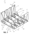
- FIG. 3 is a perspective view of an embodiment of a cradle assembly made in accordance with the current invention.
- FIG. 4 is a partial detailed view of one embodiment of a stanchion, padded support, and positioning system made in accordance with the current invention.
- FIG. 5 is an end view of one embodiment of the current invention showing an example of the various positionings of the padded support in a cradle assembly made in accordance with the current invention.
- FIG. 6 is an end view similar to FIG. 5 .
- FIG. 6 shows examples of various positionings and engagements of padding supports to the bottom of watercraft.
- FIG. 7 is a bottom view of an embodiment of a cradle assembly made in accordance with the current invention shown supporting the bottom of watercraft.
- FIG. 8 is a side view of an embodiment of the cradle assembly shown in FIGS. 3–7 .
- FIG. 9 is a side elevation view of an embodiment of the cradle assembly as shown in FIGS. 3–8 shown supporting a watercraft.
- FIG. 10 is a perspective view of an alternate embodiment of a cradle assembly made in accordance with the current invention.
- FIG. 11 is a perspective view of an alternate stanchion and padded support made in accordance with the current invention.
- FIG. 12 is a side view of an alternate stanchion and padded support made in accordance with the current invention.
- a cradle assembly is generally shown and designated by the numeral 10 .
- the cradle assembly ( 10 ) is for moving and positioning an item ( 114 ) with respect to a support module ( 112 ) in a storage assembly ( 100 ).
- the item ( 114 ) includes a bottom ( 116 ) that can be irregularly shaped.
- the item ( 114 ) is a watercraft and the support module ( 112 ) is in a watercraft storage assembly.
- the storage assembly ( 100 ) preferably includes a support wall ( 118 ), at least two support modules ( 112 ) mounted and stacked in a relationship to the support wall ( 118 ) wherein each support module ( 112 ) includes a pair of cantilever beams ( 120 ) having opposing ends ( 122 and 124 ).
- the first opposing end ( 122 ) is attached to the support wall ( 118 ), while the other opposing end ( 124 ) cantilevers out from the support wall ( 118 ).
- a remote support unit ( 126 ) is spaced from the support wall ( 118 ) in a direction of the opposing end ( 124 ).
- the remote support unit ( 26 ) extends beyond the opposing end ( 124 ) of the pair of cantilever beams ( 120 ).
- the cradle assembly ( 10 ) comprises a plurality of cradle beams ( 12 ), at least one cradle wall ( 14 ) vertically extending upward from one of the cradle beams ( 12 ), and at least one stanchion ( 16 ) vertically extending upward from one of the cradle beams ( 12 ). Additionally, the cradle assembly ( 10 ) comprises a padded support ( 18 ) operatively attached to the stanchion ( 16 ) and positioned to engage the bottom ( 116 ) of the watercraft ( 114 ) as the cradle assembly ( 10 ) moves the watercraft ( 114 ) with respect to the support module ( 112 ).
- a positioning system ( 20 ) is operatively connected to the padded support ( 18 ) to position the padded support ( 18 ) to selectively engage the bottom ( 116 ) of the watercraft ( 114 ).
- the padded support ( 18 ) is pivotally connected to the stanchion ( 16 ) and moveable in both a horizontal and vertical direction with respect to the cradle beams ( 12 ).
- the cradle assembly ( 10 ) further includes a guidearm ( 22 ) pivotally attached to the stanchion ( 16 ) and the padded support ( 18 ).
- the guidearm ( 22 ) is positioned to horizontally and vertically vary the alignment of the padded support ( 18 ) with respect to the cradle beams ( 12 ).
- the positioning system ( 20 ) is operatively connected to the guidearm ( 22 ) to rotate the guidearm ( 22 ) about the attachment between the guidearm ( 22 ) and the stanchion ( 16 ). This rotation of the guidearm ( 22 ) by the positioning system ( 20 ) varies the location of the padded support ( 18 ) with respect to the cradle beams ( 12 ).
- the padded supports ( 18 ) provide contact and support to a watercraft ( 114 ).
- the padded supports ( 18 ) nest with the various types of bottoms ( 116 ) for the watercraft ( 114 ), such as platoons, tri-hulls, catamaran, cigarette boats, and other various types of flotation devices.
- the padded supports ( 18 ) can provide automatic, gravity activated positioning to substantially align to the slope of the bottom ( 116 ) of the watercraft ( 114 ), including the length ( 48 ) and width ( 50 ).
- the multiple banks of padded supports ( 18 ) adjust for the deadrise and step in the bottom ( 116 ) of the watercraft ( 114 ).
- the padded support ( 18 ) is a pair of guide rollers rotatably attached to the guidearm ( 22 ) by an armature ( 24 ), which is preferably “V” shaped.
- the armature ( 24 ) facilitates the engagement of the pair of guiderollers ( 23 ) to the bottom ( 116 ), or hull ( 116 ), of the watercraft ( 114 ).
- the armatures ( 24 ) can have a spring loaded attachments to the guidearms ( 22 ). Additionally, the pair of guiderollers ( 23 ) protects and grips the watercraft ( 114 ).
- the adjacent cradle beams ( 12 ) are spaced a distance ( 26 ) apart and the pair of guiderollers ( 23 ) substantially spans that distance ( 26 ).
- the pair of guiderollers ( 23 ) is rotatively connected to the adjacent cradlebeams ( 12 ) and, as such, substantially spans the entire distance ( 26 ).
- the various steps, crease and curvatures of the bottom ( 116 ) of the watercraft ( 114 ) can fit within the gap between the pair of guiderollers ( 23 ).
- the rotateable attachment of the armature ( 24 ) to the guidearm ( 22 ) allows the pivoting of the pair of guiderollers ( 23 ) with respect to the guidearm ( 22 ). Additionally, the pivotal attachment between the guidearm ( 22 ) and the stanchion ( 16 ) allows a rotation of the guidearm ( 22 ) about that pivotable attachment between the guidearm ( 22 ) and the stanchion ( 16 ).
- the positioning system ( 20 ) includes a plurality of gear boxes ( 28 ) that can include motors used to drive the various aspects of the cradle assembly ( 10 ).
- the gear boxes ( 28 ) are operatively attached to various drive rods ( 30 ) used to transmit the power and movement from the gear boxes ( 28 ) to the stanchion ( 16 ) and padded supports ( 18 ).
- the drive rods ( 30 ) are supported by rod supports ( 32 ).
- the positioning system ( 20 ) can be manually or automatically controlled.
- the gearboxes ( 28 ) can be used in conjunction with the electric motors but can also be manually driven, such as with levered screwdriver handles, or hydraulically driven with pumps and controllers.
- the drive rods ( 30 ) are connected to moveable drive rods ( 31 ) by to the universal joints ( 34 ).
- the moveable drive rods ( 31 ) engage the guidearms ( 22 ) in order to transmit movement to the guidearms ( 22 ) and subsequently the pair of guided rollers ( 23 ).
- the drive rods ( 30 ) can extend upward within the cradle walls ( 14 ) as needed to properly control and operate the cradle assembly ( 10 ).
- a control connection ( 36 ) can be used to link the positioning system ( 20 ) to a remote location wherein the user can control the cradle assembly ( 10 ).
- the armature ( 24 ) translates along the length of the moveable drive rod ( 31 ). This translation causes the guidearm to rotate ( 22 ) and, as such, reposition the pair of guiderollers ( 23 ).
- the universal joint ( 34 ) allows the moveable drive rod ( 31 ) to pivot about the universal joint ( 34 ) allowing proper translation of the guidearm ( 22 ) along the moveable drive rod ( 31 ) and proper rotation about the guidearm's ( 22 ) connection to the stanchion ( 16 ).
- the cradle assembly ( 10 ) includes a floating centering assembly ( 38 ) attached to the cradle wall ( 14 ).
- the floating centering assembly ( 38 ) comprises at least a pair of buoyant arms ( 40 ) to direct the watercraft ( 114 ) to the center ( 42 ) of the cradle assembly ( 10 ) by applying pressure to the sides of the watercraft ( 114 ).
- the floating centering assembly ( 38 ) can include padding ( 39 ), or carpeting ( 39 ), to protect the engagement between the floating centering assembly ( 38 ) and the watercraft ( 114 ).
- the cradle assembly ( 10 ) further includes a first side ( 44 ) and a second side ( 46 ) wherein each stanchion ( 16 ) and padded support ( 18 ) that is positioned proximate to the first side ( 44 ) includes a reciprocal stanchion ( 16 ) and padded support ( 18 ) positioned proximate to the second side.
- the stanchion ( 16 ) and padded supports ( 18 ) have an opposing stanchion ( 16 ) and padded support ( 18 ) in order to provide proper support and weight distribution for the watercraft ( 114 ).
- the watercraft ( 114 ) can have a length ( 48 ) wherein the bottom ( 116 ) varies along the length ( 48 ).
- the positioning system ( 20 ) is aligned within the cradle assembly ( 10 ) to selectively position each padded support ( 18 ) to correspond to the variance along the length ( 48 ) of the bottom ( 116 ) of the watercraft ( 114 ).
- the watercraft includes a width ( 50 ) wherein the positioning system ( 20 ) selectively spaces the reciprocal padded supports ( 18 ) from each other a distance, or a width, that is less than the width ( 50 ) of the watercraft ( 114 ).
- the cradle assembly ( 10 ) includes a stanchion ( 52 ) that is slideably connected to one of the cradle beams ( 12 ) such that the stanchion ( 52 ) is horizontally positionable with respect to the cradle beam ( 12 ). Additionally, this cradle assembly ( 10 ) includes a padded support ( 54 ) that is slideably connected to the stanchion ( 52 ) and moveable in a vertical direction with respect to the cradle beam ( 12 ).
- the stanchion ( 52 ) can include a threaded receptor ( 56 ) attached to a threaded drive rod ( 58 ) used to slide the stanchion ( 52 ) with respect to the cradle beam ( 12 ). Additionally the stanchion ( 52 ) can include alignment pin ( 60 ) used to facilitate the positioning of the stanchion ( 52 ) on the cradle beam ( 12 ).
- the padded support ( 54 ) comprises a tubular stem ( 62 ) designed to mate with an opening ( 64 ) in the stanchion ( 52 ).
- the tubular stem ( 62 ) can be positioned with respect to the opening ( 64 ) by pins, fasteners, clamps and other devices known in the art to removeably fix objects in relationship to one another.
- This padded support ( 54 ) is pivotally fixed to the tubular stem ( 62 ). As such the orientation of the padded support ( 54 ) can vary with respect to the cradle beam ( 12 ).
- the padded support ( 54 ) is preferably a polyurethane pad for protected gripping of the watercraft ( 114 ).
Landscapes
- Engineering & Computer Science (AREA)
- Mechanical Engineering (AREA)
- Ocean & Marine Engineering (AREA)
- Packaging Of Machine Parts And Wound Products (AREA)
- Automatic Assembly (AREA)
Abstract
A cradle assembly for moving and positioning an item with respect to a support module in a storage assembly with the item including a bottom. The cradle assembly comprises a plurality of cradle beams, at least one cradle wall vertically extending upward from the plurality of cradle beams, and at least one stanchion vertically extending upward from one of the cradle beams. A padded support is operatively attached to the stanchion and positioned to engage the bottom of the item as a cradle assembly moves the item with respect to the support module. A positioning system is operatively connected to the padded support to horizontally and vertically position the padded support with respect to the plurality of the cradle beams to selectively engage the bottom of the item. Each stanchion and padded support includes a reciprocal stanchion and padded support, wherein positioning system selectively spaces the reciprocal padded supports from each other a width that is less than the width of the item being transported.
Description
This application is a Non-Provisional Utility application which claims benefit of co-pending U.S. patent application Ser. No. 60/490,066 filed Jul. 25, 2003, entitled “Improved Cradle For A Watercraft Storage System” which is hereby incorporated by reference in its entirety.
The present invention relates generally to cradle assemblies for moving items into and out of storage, especially the movement of items with irregular bottoms, or lower regions, into which a cradle assembly engages. More particularly, but not by way of limitation, the present invention relates to an improvement to a cradle assembly for the dry storage of watercraft.
The current improvement to such cradle assemblies enhances the engagement between the cradle assembly and the bottom, or hull, of the watercraft. Specifically the improvement includes adjustable supports designed to be aligned within the cradle to substantially conform to the general shape of the hull of the watercraft in order to better engage, support and transport the watercraft.
It will be appreciated by those skilled in the art that watercraft transportation devices have existed for many years. However, most of these transportation devices are in the form of trailers or land anchored platforms that use the watercraft's power and/or a crank to pull the watercraft out of the water by its bow. For example U.S. Pat. Nos. 6,612,602, 6,099,014, 5,882,170, 6,520,728, 6,189,909, 6,446,997, 6,719,317, 6,752,099, 6,644,231, 6,490,987, 6,327,990, and 6,263,820, all disclose such transportation devices.
Additionally, the dry storage of watercraft is becoming increasingly popular over the years. This dry dock storage includes a stacked or vertical arrangement of vertical watercraft lifted from the water's surface and placed in the stacked arrangements. For example, U.S. Pat. No. 6,007,288, which is hereby incorporated by reference in its entirety, discloses one such watercraft storage system. However, the conventional art has a drawback based on the wide variety of watercraft that is currently popular. This wide variety of watercraft varies in length, depth and width along with various undulations and configurations that comprise the hulls of these watercraft. As such, any lifting apparatus used to place the watercraft from the water surface into the storage system should be able to handle this wide variety of watercraft. However, currently the surfaces of the lifting apparatus in the conventional systems that move the watercraft from the water surface to the dry storage area lack the capability and flexibility to vary their engagement locations in order to adapt to the variance in the hulls of the watercraft.
As such, what is lacking in the art is a cradle assembly that can vary its engagement locations to substantially adapt to the variance in the bottoms, or hulls, of watercraft in order to transport that watercraft to a storage area.
The present invention provides for an adjustable cradle support system that can be either manually adjusted or automatically adjusted to accommodate a larger selection of boats. The system can be preprogrammed in an unloaded state, to fit the popular boat bottom configurations. This adjustment can be computerized to make the adjustment prior to moving the boat into its birth or launching into the water. The automation of this system can be setup by bar code, card number, punch code or magnetic tape card and possibly a number of different identification systems. Once a user actuates the automated system, his particular boat can be identified and a series of electric motors can be actuated to operate drive shafts to position the screw drives so that roller support will fit beneath the boat hull and be positioned to lift the boat out of the water and moved to its racked position.
Disclosed herein is a cradle assembly for moving and positioning an item with respect to a support module in a storage assembly with the item including a bottom. The cradle assembly comprises a plurality of cradle beams, at least one cradle wall vertically extending upward from the plurality of cradle beams, and at least one stanchion vertically extending upward from one of the cradle beams. Additionally, the cradle assembly comprises a padded support operatively attached to the stanchion and positioned to engage the bottom of the item as a cradle assembly moves the item with respect to the support module. Also, the cradle assembly comprises a positioning system operatively connected to the padded support to horizontally and vertically position the padded support with respect to the plurality of the cradle beams to selectively engage the bottom of the item. The cradle assembly also includes a first and second side wherein each stanchion and padded support positioned proximate to the first side includes a reciprocal stanchion and padded support positioned proximate to the second side. As such, the positioning system selectively spaces the reciprocal padded supports from each other a width that is less than the width of the item being transported.
In an embodiment the cradle assembly is used to move and position a watercraft with respect to a support module positioned in a watercraft storage assembly wherein the watercraft has an irregular bottom. In this embodiment the padded support is pivotally connected to the stanchion and moveable in both a horizontal and vertical direction with respect to the cradle beams. Additionally, a guidearm is pivotally attached to the stanchion and the padded support wherein the guidearm is positioned to horizontally and vertically vary the alignment of the padded support with respect to the cradle beams. The positioning system is operatively connected to the guidearm to rotate the guidearm about the attachment in between the guidearm and the stanchion such that the rotation of the guidearm by the positioning system varies the location of the padded support with respect to the cradle beams.
In a preferred embodiment the padded support is a pair of guide rollers rotatively attached to the guidearm for protective gripping of the watercraft. Additionally, the adjacent cradle beams are spaced a distance apart and the pair of guiderollers substantially spans that distance. Additionally, the pair of guiderollers can be rotatively connected to adjacent cradle beams in order to span the distance between the cradle beams.
In an alternative embodiment the padded support is slideably connected to the stanchion and moveable in a vertical direction with respect to the plurality of cradle beams. The padded support is pivotably connected to the stanchion to vary the orientation of the padded support with respect to the cradle beams and the padded support is a polyurethane pad for protective gripping of the watercraft. Additionally, the stanchion itself is slideably connected to one of the cradle beams and is horizontally positionable with respect to that cradle beam.
As such it is an object of the present invention to provide a cradle assembly for moving and positioning items with respect to a support module in a storage assembly.
Another object of the present invention is to provide a cradle assembly for moving and positioning a watercraft with respect to a support module and a watercraft storage assembly wherein the watercraft includes an irregular bottom.
Yet another object of the present invention is to provide a cradle assembly having a padded support area that is moveable to selectively engage the hulls of various watercrafts.
And yet still another object of the present invention is to provide a cradle assembly that includes a positioning system that can align ports to the best support locations on the hull of a watercraft.
Other and further objects features and advantages of the present invention will be readily apparent to those skilled in the art upon reading of the following disclosure when taken in conjunction with the accompanying drawings.
Referring now generally now to FIGS. 1–12 , a cradle assembly is generally shown and designated by the numeral 10. The cradle assembly (10) is for moving and positioning an item (114) with respect to a support module (112) in a storage assembly (100). The item (114) includes a bottom (116) that can be irregularly shaped. Preferably the item (114) is a watercraft and the support module (112) is in a watercraft storage assembly. The storage assembly (100) preferably includes a support wall (118), at least two support modules (112) mounted and stacked in a relationship to the support wall (118) wherein each support module (112) includes a pair of cantilever beams (120) having opposing ends (122 and 124). The first opposing end (122) is attached to the support wall (118), while the other opposing end (124) cantilevers out from the support wall (118). Additionally a remote support unit (126) is spaced from the support wall (118) in a direction of the opposing end (124). The remote support unit (26) extends beyond the opposing end (124) of the pair of cantilever beams (120).
The cradle assembly (10) comprises a plurality of cradle beams (12), at least one cradle wall (14) vertically extending upward from one of the cradle beams (12), and at least one stanchion (16) vertically extending upward from one of the cradle beams (12). Additionally, the cradle assembly (10) comprises a padded support (18) operatively attached to the stanchion (16) and positioned to engage the bottom (116) of the watercraft (114) as the cradle assembly (10) moves the watercraft (114) with respect to the support module (112). Additionally, a positioning system (20) is operatively connected to the padded support (18) to position the padded support (18) to selectively engage the bottom (116) of the watercraft (114). The padded support (18) is pivotally connected to the stanchion (16) and moveable in both a horizontal and vertical direction with respect to the cradle beams (12).
In a preferred embodiment the cradle assembly (10) further includes a guidearm (22) pivotally attached to the stanchion (16) and the padded support (18). The guidearm (22) is positioned to horizontally and vertically vary the alignment of the padded support (18) with respect to the cradle beams (12). The positioning system (20) is operatively connected to the guidearm (22) to rotate the guidearm (22) about the attachment between the guidearm (22) and the stanchion (16). This rotation of the guidearm (22) by the positioning system (20) varies the location of the padded support (18) with respect to the cradle beams (12).
The padded supports (18) provide contact and support to a watercraft (114). The padded supports (18) nest with the various types of bottoms (116) for the watercraft (114), such as platoons, tri-hulls, catamaran, cigarette boats, and other various types of flotation devices. The padded supports (18) can provide automatic, gravity activated positioning to substantially align to the slope of the bottom (116) of the watercraft (114), including the length (48) and width (50). The multiple banks of padded supports (18) adjust for the deadrise and step in the bottom (116) of the watercraft (114).
In this embodiment the padded support (18) is a pair of guide rollers rotatably attached to the guidearm (22) by an armature (24), which is preferably “V” shaped. The armature (24) facilitates the engagement of the pair of guiderollers (23) to the bottom (116), or hull (116), of the watercraft (114). The armatures (24) can have a spring loaded attachments to the guidearms (22). Additionally, the pair of guiderollers (23) protects and grips the watercraft (114).
The adjacent cradle beams (12) are spaced a distance (26) apart and the pair of guiderollers (23) substantially spans that distance (26). Most preferably, the pair of guiderollers (23) is rotatively connected to the adjacent cradlebeams (12) and, as such, substantially spans the entire distance (26). The various steps, crease and curvatures of the bottom (116) of the watercraft (114) can fit within the gap between the pair of guiderollers (23).
The rotateable attachment of the armature (24) to the guidearm (22) allows the pivoting of the pair of guiderollers (23) with respect to the guidearm (22). Additionally, the pivotal attachment between the guidearm (22) and the stanchion (16) allows a rotation of the guidearm (22) about that pivotable attachment between the guidearm (22) and the stanchion (16).
The positioning system (20) includes a plurality of gear boxes (28) that can include motors used to drive the various aspects of the cradle assembly (10). The gear boxes (28) are operatively attached to various drive rods (30) used to transmit the power and movement from the gear boxes (28) to the stanchion (16) and padded supports (18). The drive rods (30) are supported by rod supports (32). The positioning system (20) can be manually or automatically controlled. For example, the gearboxes (28) can be used in conjunction with the electric motors but can also be manually driven, such as with levered screwdriver handles, or hydraulically driven with pumps and controllers.
Additionally, the drive rods (30) are connected to moveable drive rods (31) by to the universal joints (34). The moveable drive rods (31) engage the guidearms (22) in order to transmit movement to the guidearms (22) and subsequently the pair of guided rollers (23). The drive rods (30) can extend upward within the cradle walls (14) as needed to properly control and operate the cradle assembly (10). A control connection (36) can be used to link the positioning system (20) to a remote location wherein the user can control the cradle assembly (10).
As best seen in FIGS. 5 and 6 , as the preferably threaded moveable drive rods (31) rotate the guidearm (22), the armature (24) translates along the length of the moveable drive rod (31). This translation causes the guidearm to rotate (22) and, as such, reposition the pair of guiderollers (23). The universal joint (34) allows the moveable drive rod (31) to pivot about the universal joint (34) allowing proper translation of the guidearm (22) along the moveable drive rod (31) and proper rotation about the guidearm's (22) connection to the stanchion (16).
Additionally, the cradle assembly (10) includes a floating centering assembly (38) attached to the cradle wall (14). The floating centering assembly (38) comprises at least a pair of buoyant arms (40) to direct the watercraft (114) to the center (42) of the cradle assembly (10) by applying pressure to the sides of the watercraft (114). The floating centering assembly (38) can include padding (39), or carpeting (39), to protect the engagement between the floating centering assembly (38) and the watercraft (114).
The cradle assembly (10) further includes a first side (44) and a second side (46) wherein each stanchion (16) and padded support (18) that is positioned proximate to the first side (44) includes a reciprocal stanchion (16) and padded support (18) positioned proximate to the second side. Alternately stated, the stanchion (16) and padded supports (18) have an opposing stanchion (16) and padded support (18) in order to provide proper support and weight distribution for the watercraft (114).
Additionally, the watercraft (114) can have a length (48) wherein the bottom (116) varies along the length (48). The positioning system (20) is aligned within the cradle assembly (10) to selectively position each padded support (18) to correspond to the variance along the length (48) of the bottom (116) of the watercraft (114). Additionally, the watercraft includes a width (50) wherein the positioning system (20) selectively spaces the reciprocal padded supports (18) from each other a distance, or a width, that is less than the width (50) of the watercraft (114).
In an alternate embodiment the cradle assembly (10) includes a stanchion (52) that is slideably connected to one of the cradle beams (12) such that the stanchion (52) is horizontally positionable with respect to the cradle beam (12). Additionally, this cradle assembly (10) includes a padded support (54) that is slideably connected to the stanchion (52) and moveable in a vertical direction with respect to the cradle beam (12). The stanchion (52) can include a threaded receptor (56) attached to a threaded drive rod (58) used to slide the stanchion (52) with respect to the cradle beam (12). Additionally the stanchion (52) can include alignment pin (60) used to facilitate the positioning of the stanchion (52) on the cradle beam (12).
The padded support (54) comprises a tubular stem (62) designed to mate with an opening (64) in the stanchion (52). The tubular stem (62) can be positioned with respect to the opening (64) by pins, fasteners, clamps and other devices known in the art to removeably fix objects in relationship to one another. This padded support (54) is pivotally fixed to the tubular stem (62). As such the orientation of the padded support (54) can vary with respect to the cradle beam (12). In this embodiment the padded support (54) is preferably a polyurethane pad for protected gripping of the watercraft (114).
Thus, although there have been described particular embodiments of the present invention of a new and useful “Improved Cradle For Item Transportation Especially Watercraft Storage”, it is not intended that such references be construed as limitations upon the scope of this invention except as set forth in the following claims.
Claims (20)
1. A cradle assembly for moving and positioning a watercraft with respect to a support module in a watercraft storage assembly, the watercraft including a bottom, the cradle assembly comprising
a plurality of cradle beams;
at least one cradle wall vertically extending upward from one of the cradle beams;
at least one stanchion vertically extending upward from one of the cradle beams;
a padded support operatively attached to the at least one stanchion and positioned to engage the bottom of the watercraft as the cradle assembly moves the watercraft with respect to the support module;
a positioning system operatively connected to the padded support to position the padded support to selectively engage the bottom of the watercraft; and
wherein adjacent cradle beams are spaced a distance apart and the padded support substantially spans that distance.
2. The cradle assembly of claim 1 , wherein the padded support is pivotally connect to the stanchion and movable in both a horizontal and a vertical direction with respect to the plurality of cradle beams.
3. The cradle assembly of claim 1 , further including a guide arm pivotally attached to the stanchion and the padded support and positioned to horizontally and vertically vary the alignment of the padded support with respect to the plurality of cradle beams.
4. The cradle assembly of claim 3 , wherein the positioning system is operatively connected to the guide arm to rotate the guide arm about the attachment between the guide arm and the stanchion.
5. The cradle assembly of claim 4 , wherein the rotation of the guide arm by the positioning system varies the location of the padded support with respect to the plurality of cradle beams.
6. The cradle assembly of claim 5 , wherein the padded support is a pair of guide rollers rotatably attached to the guide arm for protected gripping of the watercraft.
7. The cradle assembly of claim 1 , wherein the cradle assembly includes a first and second side and each stanchion and padded support positioned proximate the first side includes a reciprocal stanchion and padded support positioned proximate the second side.
8. The cradle assembly of claim 7 , wherein:
the watercraft includes a length and the bottom of the watercraft varies along the length; and
the positioning system is aligned to selectively position each padded support to correspond to the variance on the bottom of the watercraft.
9. The cradle assembly of claim 8 , wherein:
the watercraft includes a width, and
the positioning system selectively spaces the reciprocal padded supports from each other a width less than the width of the watercraft.
10. A cradle assembly for moving and positioning a watercraft with respect to a support module in a watercraft storage assembly, the watercraft including a bottom, the cradle assembly comprising
a plurality of cradle beams;
at least one cradle wall vertically extending upward from one of the cradle beams;
at least one stanchion vertically extending upward from one of the cradle beams;
a padded support operatively attached to the at least one stanchion and positioned to engage the bottom of the watercraft as the cradle assembly moves the watercraft with respect to the support module;
a positioning system operatively connected to the padded support to position the padded support to selectively engage the bottom of the watercraft;
further including a guide arm pivotally attached to the stanchion and the padded support and positioned to horizontally and vertically vary the alignment of the padded support with respect to the plurality of cradle beams;
wherein the positioning system is operatively connected to the guide arm to rotate the guide arm about the attachment between the guide arm and the stanchion;
wherein the rotation of the guide arm by the positioning system varies the location of the padded support with respect to the plurality of cradle beams;
wherein the padded support is a pair of guide rollers rotatably attached to the guide arm for protected gripping of the watercraft; and
wherein adjacent cradle beams are spaced a distance apart and the pair of guide rollers substantially spans that distance.
11. The cradle assembly of claim 10 , wherein the pair of guide rollers are rotatably connected to adjacent cradle beams.
12. A cradle assembly for moving and positioning a watercraft with respect to a support module in a watercraft storage assembly, the watercraft including a bottom, the cradle assembly comprising
a plurality of cradle beams;
at least one cradle wall vertically extending upward from one of the cradle beams;
at least one stanchion vertically extending upward from one of the cradle beams;
a padded support operatively attached to the at least one stanchion and positioned to engage the bottom of the watercraft as the cradle assembly moves the watercraft with respect to the support module;
a positioning system operatively connected to the padded support to position the padded support to selectively engage the bottom of the watercraft; and
wherein the stanchion is slideably connected to the one of the cradle beams and horizontally positionable with respect to one of the cradle beams.
13. The cradle assembly of claim 12 , wherein the padded support is slideably connect to the stanchion and movable in a vertical direction with respect to the plurality of cradle beams.
14. The cradle assembly of claim 13 , wherein the padded support is pivotally connect to the stanchion to vary the orientation of the padded support with respect to the plurality of cradle beams.
15. The cradle assembly of claim 14 , wherein the padded support is a polyurethane pad for protected gripping of the watercraft.
16. A cradle assembly for moving and positioning a watercraft with respect to a support module in a watercraft storage assembly, the watercraft including a bottom, the cradle assembly comprising
a plurality of cradle beams;
at least one cradle wall vertically extending upward from one of the cradle beams;
at least one stanchion vertically extending upward from one of the cradle beams;
a padded support operatively attached to the at least one stanchion and positioned to engage the bottom of the watercraft as the cradle assembly moves the watercraft with respect to the support module;
a positioning system operatively connected to the padded support to position the padded support to selectively engage the bottom of the watercraft; and
further including a floating centering assembly attached to the cradle wall, the floating centering assembly attached to the cradle wall and comprising at least one pair of buoyant arms to direct the watercraft to the center of the cradle assembly by applying pressure to sides of the watercraft.
17. A cradle assembly for moving and positioning an item with respect to a support module in a storage assembly, the item including a bottom, the cradle assembly comprising
a plurality of cradle beams;
at least one cradle wall vertically extending upward from the plurality of cradle beams;
at least one stanchion vertically extending upward from one of the cradle beams;
a padded support operatively attached to the at least one stanchion and positioned to engage the bottom of the item as the cradle assembly moves the item with respect to the support module; and
a positioning system operatively connected to the padded support to horizontally and vertically position the padded support with respect to the plurality of cradle beams to selectively engage the bottom of the item;
wherein adjacent cradle beams are spaced a distance apart and the padded support substantially spans that distance; and
wherein the stanchion is slideably connected to the one of the cradle beams and horizontally positionable with respect to one of the cradle beams.
18. The cradle assembly of claim 17 , wherein the cradle assembly includes a first and second side and each stanchion and padded support positioned proximate the first side includes a reciprocal stanchion and padded support positioned proximate the second side.
19. The cradle assembly of claim 18 , wherein the positioning system selectively spaces the reciprocal padded supports from each other a width less than the width of the item.
20. A cradle assembly for use in a watercraft storage system including a support wall, at least two watercraft support modules mounted and stacked in relationship to said support wall, said support modules each including a pair of cantilever beams having opposing ends, one of each set of opposing ends being attached to said support wall and the other end of each set of opposing ends cantilevering out from said support wall, a remote support unit spaced from said support wall in a direction of the other opposing ends of said beams and beyond the said other ends of said beams, the cradle assembly comprising:
a plurality of cradle beams having a left and right side;
a cradle wall vertically extending upward from each side of the cradle beams;
a plurality of stanchions vertically extending upward from each of the cradle beams;
a padded support operatively connect to the stanchion and positionable in both a horizontal and a vertical direction with respect to the plurality of cradle beams to engage the bottom of the watercraft as the cradle assembly moves the watercraft with respect to the cantilever beams; and
a positioning system operatively connected to the padded support and aligned to selectively position each padded support to correspond to the variance on the bottom of the watercraft.
Priority Applications (2)
| Application Number | Priority Date | Filing Date | Title |
|---|---|---|---|
| US10/899,384 US7112007B2 (en) | 2003-07-25 | 2004-07-26 | Cradle for item transportation and storage, especially watercraft storage |
| US11/338,865 US7367747B2 (en) | 2003-07-25 | 2006-01-24 | Adjustable and extending transport cradle for watercraft |
Applications Claiming Priority (2)
| Application Number | Priority Date | Filing Date | Title |
|---|---|---|---|
| US49006603P | 2003-07-25 | 2003-07-25 | |
| US10/899,384 US7112007B2 (en) | 2003-07-25 | 2004-07-26 | Cradle for item transportation and storage, especially watercraft storage |
Related Child Applications (1)
| Application Number | Title | Priority Date | Filing Date |
|---|---|---|---|
| US11/338,865 Continuation-In-Part US7367747B2 (en) | 2003-07-25 | 2006-01-24 | Adjustable and extending transport cradle for watercraft |
Publications (2)
| Publication Number | Publication Date |
|---|---|
| US20050035259A1 US20050035259A1 (en) | 2005-02-17 |
| US7112007B2 true US7112007B2 (en) | 2006-09-26 |
Family
ID=34115350
Family Applications (1)
| Application Number | Title | Priority Date | Filing Date |
|---|---|---|---|
| US10/899,384 Expired - Fee Related US7112007B2 (en) | 2003-07-25 | 2004-07-26 | Cradle for item transportation and storage, especially watercraft storage |
Country Status (2)
| Country | Link |
|---|---|
| US (1) | US7112007B2 (en) |
| WO (1) | WO2005012076A2 (en) |
Cited By (10)
| Publication number | Priority date | Publication date | Assignee | Title |
|---|---|---|---|---|
| US20060177271A1 (en) * | 2003-07-25 | 2006-08-10 | Maffett William C | Adjustable and extending transport cradle for watercraft |
| US20080075568A1 (en) * | 2006-09-25 | 2008-03-27 | Benedict Charles E | Overhead boat storage system |
| US20080101882A1 (en) * | 2006-10-25 | 2008-05-01 | Neland Richard L | Boat and automobile storage apparatus |
| US20090304480A1 (en) * | 2006-03-02 | 2009-12-10 | Maffstack, Llc | Large-Scale Watercraft Storage System |
| US20100196097A1 (en) * | 2007-06-07 | 2010-08-05 | Lee Kyong-Hyung | Device for pulling out a ship |
| US20110052350A1 (en) * | 2008-01-28 | 2011-03-03 | Lydle Richard C | Watercraft dry dock storage systems and methods |
| US9745033B1 (en) | 2013-03-15 | 2017-08-29 | Brian Maffett | Boat storage stacker with rotatable and offset mast |
| US10336415B2 (en) * | 2016-08-02 | 2019-07-02 | Autolift, LLC | Watercraft lift system and method |
| US11242196B2 (en) * | 2017-12-21 | 2022-02-08 | Ufp Industries, Inc. | Transport shipping container for personal watercraft |
| US12187394B2 (en) | 2016-08-02 | 2025-01-07 | Autolift, LLC | Watercraft lift system and method |
Families Citing this family (7)
| Publication number | Priority date | Publication date | Assignee | Title |
|---|---|---|---|---|
| US20070207015A1 (en) * | 2004-01-28 | 2007-09-06 | Rosenberg Christian F | Large-Scale Watercraft Storage Facility |
| NL2005907C2 (en) * | 2010-12-22 | 2012-06-25 | Kig Heerenveen Bv | DEVICE FOR SUPPORTING AN OBJECT. |
| MA40140A1 (en) | 2014-09-26 | 2018-09-28 | Giroud Gerard | System, method and devices for maneuvering boats stored in a dry dock using a traveling crane and a sliding tower |
| US11904990B2 (en) * | 2020-09-02 | 2024-02-20 | Innovative Outdoor Solutions, Inc. | Floating drive-on pontoon port |
| KR102598147B1 (en) * | 2021-09-03 | 2023-11-06 | 한국해양과학기술원 | A experimental submarine model fixing device and fixing method using the same |
| CN114102488B (en) * | 2021-11-08 | 2023-12-26 | 中船澄西船舶修造有限公司 | GE marine foot cover insert assembly tooling |
| KR102667589B1 (en) * | 2022-12-16 | 2024-05-22 | 한국해양과학기술원 | supporting device for model underwater moving object |
Citations (43)
| Publication number | Priority date | Publication date | Assignee | Title |
|---|---|---|---|---|
| US1515435A (en) * | 1924-06-30 | 1924-11-11 | William G Glover | Bilge block, keel block, and the like |
| GB882343A (en) | 1960-03-10 | 1961-11-15 | James Edwards Wheeler | Storage apparatus |
| US3341164A (en) * | 1965-10-22 | 1967-09-12 | Jr Fred B Ewing | Device for supporting an arcuate surface |
| US3385458A (en) | 1966-11-28 | 1968-05-28 | Joseph N. Gresham | Boat storage rack |
| US3786942A (en) | 1970-02-09 | 1974-01-22 | E Dane | Dry sail marina |
| US3802580A (en) | 1973-02-22 | 1974-04-09 | Supreme Equip & Syst | Means for selectively removing a preselected number of articles from an inventory storage means |
| US4070979A (en) | 1977-03-22 | 1978-01-31 | Otis Roger W | Floating dry storage facility for small boats |
| US4190013A (en) | 1977-03-22 | 1980-02-26 | Otis Roger W | Floating dry storage facility for small boats |
| US4227828A (en) * | 1977-06-01 | 1980-10-14 | Ivanov Jury P | Building berth vessel support and handling system |
| US4268207A (en) | 1979-07-06 | 1981-05-19 | Eaton Corporation | Load support and shuttle |
| US4372724A (en) | 1979-06-23 | 1983-02-08 | Stolzer Lagertechnik Gesellschaft Mit Beschrankter Haftung | Apparatus and method for storing rod stock and supplying same to a servicing machine |
| US4488847A (en) | 1981-08-21 | 1984-12-18 | Keuro Maschinenbau Gesellschaft Mit Beschrankter Haftung & Co. Kommanditgesellschaft | Apparatus for storing rod-shaped material |
| FR2552411A1 (en) | 1983-09-22 | 1985-03-29 | Betax Beratung Entwicklung Tec | Dry storage for small boats |
| US4640214A (en) | 1985-01-18 | 1987-02-03 | Bruns John H | Modular multi-storage building |
| US4726316A (en) | 1985-01-18 | 1988-02-23 | Bruns John H | Floating storage building |
| US4787804A (en) | 1985-09-16 | 1988-11-29 | Aktiebolaget Knight Konsulterande Ingenjorer | Material handling system |
| US4797055A (en) | 1986-12-18 | 1989-01-10 | Atlas Marine Technologies | Load moving apparatus |
| JPH0248311A (en) | 1988-08-05 | 1990-02-19 | Kawasaki Heavy Ind Ltd | Three-dimensional article accommodating equipment |
| JPH0288853A (en) | 1988-09-27 | 1990-03-29 | Furukawa Co Ltd | Three-dimensional housing apparatus |
| JPH02183055A (en) | 1989-01-09 | 1990-07-17 | Daiko:Kk | Unloading device of small sized ship |
| US4953488A (en) | 1988-10-25 | 1990-09-04 | Heinrich Heidtmann | Boat carrousel |
| JPH02241891A (en) | 1989-03-15 | 1990-09-26 | Daiko:Kk | Ship conveying device at ship dock |
| US4971505A (en) | 1986-09-25 | 1990-11-20 | Frank Sawyer | Architectural structure for occupancy and parking |
| US4979869A (en) | 1987-10-06 | 1990-12-25 | Outboard Marine Corporation | Method for storing boats in a storage building |
| US5011357A (en) | 1989-06-09 | 1991-04-30 | Richard Studler | Boat/auto parking system for marina |
| JPH03119270A (en) | 1989-09-29 | 1991-05-21 | Kawaju Koji Kk | Sliding elevator-type parking device |
| US5238348A (en) | 1988-12-13 | 1993-08-24 | Alfred Reimer | Parking system |
| US5487636A (en) | 1995-04-12 | 1996-01-30 | Mkrtchyan; Mais | Time and cost efficient storage facility |
| US5882170A (en) | 1998-04-17 | 1999-03-16 | Walton; Peter | Watercraft loading and launching apparatus |
| US6007288A (en) | 1998-01-30 | 1999-12-28 | Maffett; William C. | Watercraft storage system |
| US6099014A (en) | 1998-09-08 | 2000-08-08 | Mclaughlin; Norman L. | Boat stop |
| US6162003A (en) * | 1996-03-23 | 2000-12-19 | Gruener; Friedrich | Installation for storing objects, especially boats |
| US6189909B1 (en) | 1999-03-29 | 2001-02-20 | Michael Danchuk | Friction-reducing support member protection device |
| US6263820B1 (en) | 2000-10-18 | 2001-07-24 | Philip A. Crifase | Boat landing apparatus |
| US6327990B1 (en) | 2000-10-18 | 2001-12-11 | Philip A. Crifase | Boat landing apparatus |
| US6446997B1 (en) | 2000-12-04 | 2002-09-10 | Walter F. Bergman | Trailer for transporting an inflated raft and related equipment |
| US20020176767A1 (en) | 2001-05-25 | 2002-11-28 | Dave Gisselberg | Vessel racking system |
| US6490987B1 (en) | 2001-06-04 | 2002-12-10 | Philip A. Crifase | Boat landing apparatus with elevation device |
| US6520728B1 (en) | 2000-09-25 | 2003-02-18 | Wayne Schwitters | System and method for elevating a watercraft |
| US6612602B1 (en) | 2002-05-14 | 2003-09-02 | Charles J. Mackarvich | Boat trailer roller mount |
| US6644231B2 (en) | 2001-10-20 | 2003-11-11 | Philip A. Crifase | Boat landing apparatus |
| US6719317B1 (en) | 2001-06-11 | 2004-04-13 | Donald J. Grovender | Pontoon boat trailer |
| US6752099B1 (en) | 2002-10-22 | 2004-06-22 | Philip A. Crifase | Boat landing apparatus with removable winch |
-
2004
- 2004-07-26 WO PCT/US2004/023866 patent/WO2005012076A2/en not_active Ceased
- 2004-07-26 US US10/899,384 patent/US7112007B2/en not_active Expired - Fee Related
Patent Citations (43)
| Publication number | Priority date | Publication date | Assignee | Title |
|---|---|---|---|---|
| US1515435A (en) * | 1924-06-30 | 1924-11-11 | William G Glover | Bilge block, keel block, and the like |
| GB882343A (en) | 1960-03-10 | 1961-11-15 | James Edwards Wheeler | Storage apparatus |
| US3341164A (en) * | 1965-10-22 | 1967-09-12 | Jr Fred B Ewing | Device for supporting an arcuate surface |
| US3385458A (en) | 1966-11-28 | 1968-05-28 | Joseph N. Gresham | Boat storage rack |
| US3786942A (en) | 1970-02-09 | 1974-01-22 | E Dane | Dry sail marina |
| US3802580A (en) | 1973-02-22 | 1974-04-09 | Supreme Equip & Syst | Means for selectively removing a preselected number of articles from an inventory storage means |
| US4070979A (en) | 1977-03-22 | 1978-01-31 | Otis Roger W | Floating dry storage facility for small boats |
| US4190013A (en) | 1977-03-22 | 1980-02-26 | Otis Roger W | Floating dry storage facility for small boats |
| US4227828A (en) * | 1977-06-01 | 1980-10-14 | Ivanov Jury P | Building berth vessel support and handling system |
| US4372724A (en) | 1979-06-23 | 1983-02-08 | Stolzer Lagertechnik Gesellschaft Mit Beschrankter Haftung | Apparatus and method for storing rod stock and supplying same to a servicing machine |
| US4268207A (en) | 1979-07-06 | 1981-05-19 | Eaton Corporation | Load support and shuttle |
| US4488847A (en) | 1981-08-21 | 1984-12-18 | Keuro Maschinenbau Gesellschaft Mit Beschrankter Haftung & Co. Kommanditgesellschaft | Apparatus for storing rod-shaped material |
| FR2552411A1 (en) | 1983-09-22 | 1985-03-29 | Betax Beratung Entwicklung Tec | Dry storage for small boats |
| US4640214A (en) | 1985-01-18 | 1987-02-03 | Bruns John H | Modular multi-storage building |
| US4726316A (en) | 1985-01-18 | 1988-02-23 | Bruns John H | Floating storage building |
| US4787804A (en) | 1985-09-16 | 1988-11-29 | Aktiebolaget Knight Konsulterande Ingenjorer | Material handling system |
| US4971505A (en) | 1986-09-25 | 1990-11-20 | Frank Sawyer | Architectural structure for occupancy and parking |
| US4797055A (en) | 1986-12-18 | 1989-01-10 | Atlas Marine Technologies | Load moving apparatus |
| US4979869A (en) | 1987-10-06 | 1990-12-25 | Outboard Marine Corporation | Method for storing boats in a storage building |
| JPH0248311A (en) | 1988-08-05 | 1990-02-19 | Kawasaki Heavy Ind Ltd | Three-dimensional article accommodating equipment |
| JPH0288853A (en) | 1988-09-27 | 1990-03-29 | Furukawa Co Ltd | Three-dimensional housing apparatus |
| US4953488A (en) | 1988-10-25 | 1990-09-04 | Heinrich Heidtmann | Boat carrousel |
| US5238348A (en) | 1988-12-13 | 1993-08-24 | Alfred Reimer | Parking system |
| JPH02183055A (en) | 1989-01-09 | 1990-07-17 | Daiko:Kk | Unloading device of small sized ship |
| JPH02241891A (en) | 1989-03-15 | 1990-09-26 | Daiko:Kk | Ship conveying device at ship dock |
| US5011357A (en) | 1989-06-09 | 1991-04-30 | Richard Studler | Boat/auto parking system for marina |
| JPH03119270A (en) | 1989-09-29 | 1991-05-21 | Kawaju Koji Kk | Sliding elevator-type parking device |
| US5487636A (en) | 1995-04-12 | 1996-01-30 | Mkrtchyan; Mais | Time and cost efficient storage facility |
| US6162003A (en) * | 1996-03-23 | 2000-12-19 | Gruener; Friedrich | Installation for storing objects, especially boats |
| US6007288A (en) | 1998-01-30 | 1999-12-28 | Maffett; William C. | Watercraft storage system |
| US5882170A (en) | 1998-04-17 | 1999-03-16 | Walton; Peter | Watercraft loading and launching apparatus |
| US6099014A (en) | 1998-09-08 | 2000-08-08 | Mclaughlin; Norman L. | Boat stop |
| US6189909B1 (en) | 1999-03-29 | 2001-02-20 | Michael Danchuk | Friction-reducing support member protection device |
| US6520728B1 (en) | 2000-09-25 | 2003-02-18 | Wayne Schwitters | System and method for elevating a watercraft |
| US6263820B1 (en) | 2000-10-18 | 2001-07-24 | Philip A. Crifase | Boat landing apparatus |
| US6327990B1 (en) | 2000-10-18 | 2001-12-11 | Philip A. Crifase | Boat landing apparatus |
| US6446997B1 (en) | 2000-12-04 | 2002-09-10 | Walter F. Bergman | Trailer for transporting an inflated raft and related equipment |
| US20020176767A1 (en) | 2001-05-25 | 2002-11-28 | Dave Gisselberg | Vessel racking system |
| US6490987B1 (en) | 2001-06-04 | 2002-12-10 | Philip A. Crifase | Boat landing apparatus with elevation device |
| US6719317B1 (en) | 2001-06-11 | 2004-04-13 | Donald J. Grovender | Pontoon boat trailer |
| US6644231B2 (en) | 2001-10-20 | 2003-11-11 | Philip A. Crifase | Boat landing apparatus |
| US6612602B1 (en) | 2002-05-14 | 2003-09-02 | Charles J. Mackarvich | Boat trailer roller mount |
| US6752099B1 (en) | 2002-10-22 | 2004-06-22 | Philip A. Crifase | Boat landing apparatus with removable winch |
Non-Patent Citations (1)
| Title |
|---|
| Brochure "Marinas and Small Craft Harbors," authored by Tobiasson and Kollmeyer, published by Van Nostrand Reinhold, NY. |
Cited By (21)
| Publication number | Priority date | Publication date | Assignee | Title |
|---|---|---|---|---|
| US20060177271A1 (en) * | 2003-07-25 | 2006-08-10 | Maffett William C | Adjustable and extending transport cradle for watercraft |
| US7367747B2 (en) * | 2003-07-25 | 2008-05-06 | Maff-Stack, Llc | Adjustable and extending transport cradle for watercraft |
| US20090304480A1 (en) * | 2006-03-02 | 2009-12-10 | Maffstack, Llc | Large-Scale Watercraft Storage System |
| US9789942B2 (en) | 2006-03-02 | 2017-10-17 | Maff-Stack, Llc | Large-scale watercraft storage system |
| US20080075568A1 (en) * | 2006-09-25 | 2008-03-27 | Benedict Charles E | Overhead boat storage system |
| US7850412B2 (en) * | 2006-09-25 | 2010-12-14 | Bec Companies, Inc. | Overhead boat storage system |
| US20080101882A1 (en) * | 2006-10-25 | 2008-05-01 | Neland Richard L | Boat and automobile storage apparatus |
| US7726247B2 (en) * | 2006-10-25 | 2010-06-01 | Neland Richard L | Boat and automobile storage apparatus |
| US20100196097A1 (en) * | 2007-06-07 | 2010-08-05 | Lee Kyong-Hyung | Device for pulling out a ship |
| US8079779B2 (en) * | 2007-06-12 | 2011-12-20 | Kyong-Hyung Lee | Device for pulling out a ship |
| US8596946B2 (en) | 2008-01-28 | 2013-12-03 | The Richard C. Lydle 2008 Delaware Trust | Watercraft dry dock storage systems and methods |
| US20110052350A1 (en) * | 2008-01-28 | 2011-03-03 | Lydle Richard C | Watercraft dry dock storage systems and methods |
| US10196115B2 (en) | 2008-01-28 | 2019-02-05 | The Richard C. Lydle Revocable Trust | Watercraft dry dock storage system and method |
| US10745092B2 (en) | 2008-01-28 | 2020-08-18 | The Richard C. Lydle Revocable Trust | Watercraft dry dock storage system and method |
| US9745033B1 (en) | 2013-03-15 | 2017-08-29 | Brian Maffett | Boat storage stacker with rotatable and offset mast |
| US10336415B2 (en) * | 2016-08-02 | 2019-07-02 | Autolift, LLC | Watercraft lift system and method |
| US20190276123A1 (en) * | 2016-08-02 | 2019-09-12 | Autolift, LLC | Watercraft lift system and method |
| US11447217B2 (en) | 2016-08-02 | 2022-09-20 | Autolift, LLC | Watercraft lift system and method |
| US12187394B2 (en) | 2016-08-02 | 2025-01-07 | Autolift, LLC | Watercraft lift system and method |
| US11242196B2 (en) * | 2017-12-21 | 2022-02-08 | Ufp Industries, Inc. | Transport shipping container for personal watercraft |
| US11926469B2 (en) | 2017-12-21 | 2024-03-12 | Ufp Industries, Inc. | Transport shipping container for personal watercraft |
Also Published As
| Publication number | Publication date |
|---|---|
| WO2005012076A2 (en) | 2005-02-10 |
| WO2005012076A3 (en) | 2006-03-09 |
| US20050035259A1 (en) | 2005-02-17 |
Similar Documents
| Publication | Publication Date | Title |
|---|---|---|
| US7112007B2 (en) | Cradle for item transportation and storage, especially watercraft storage | |
| US4913080A (en) | Method for production and laying a pipeline or a cable under water | |
| US6823809B2 (en) | Floating watercraft lift apparatus and method | |
| US6915753B1 (en) | Mooring apparatus | |
| US6032601A (en) | Combination boat lift and dock | |
| US6076478A (en) | Apparatus for raising and lowering boats | |
| EP0938426A1 (en) | Floating drive-on dry dock assembly having a supporting beam | |
| US7194971B2 (en) | Lift arrangement for boats | |
| US4236477A (en) | Boat hull cleaning device | |
| CA1038239A (en) | Boat hull scrubbing apparatus | |
| US6520728B1 (en) | System and method for elevating a watercraft | |
| US5449247A (en) | Boat mooring station | |
| US5186576A (en) | Boat hull support | |
| US20040089212A1 (en) | Modular floating boat lift having aqueous hydraulic cylinder powered cradle | |
| US6209474B1 (en) | Transporter for heavy objects at sea | |
| US4955308A (en) | Floating boat lift | |
| US7367747B2 (en) | Adjustable and extending transport cradle for watercraft | |
| US3977030A (en) | Arrangement for hauling up, launching and storing of boats and the like | |
| KR20080109274A (en) | Ship lifting device | |
| EP2861902B1 (en) | Guide system and method for guiding a pipeline from a laying vessel onto the bed of a body of water | |
| US7426897B2 (en) | Mooring apparatus | |
| EP1400442A1 (en) | Mooring apparatus | |
| US3406649A (en) | Method and apparatus for drydocking a boat hull or other floating structure in a body of water | |
| US20010039911A1 (en) | Marine carrier | |
| CN119953536B (en) | A floating installation system and method for large-scale offshore photovoltaic module brackets |
Legal Events
| Date | Code | Title | Description |
|---|---|---|---|
| FPAY | Fee payment |
Year of fee payment: 4 |
|
| REMI | Maintenance fee reminder mailed | ||
| FPAY | Fee payment |
Year of fee payment: 8 |
|
| SULP | Surcharge for late payment |
Year of fee payment: 7 |
|
| FEPP | Fee payment procedure |
Free format text: MAINTENANCE FEE REMINDER MAILED (ORIGINAL EVENT CODE: REM.) |
|
| LAPS | Lapse for failure to pay maintenance fees |
Free format text: PATENT EXPIRED FOR FAILURE TO PAY MAINTENANCE FEES (ORIGINAL EVENT CODE: EXP.); ENTITY STATUS OF PATENT OWNER: SMALL ENTITY |
|
| STCH | Information on status: patent discontinuation |
Free format text: PATENT EXPIRED DUE TO NONPAYMENT OF MAINTENANCE FEES UNDER 37 CFR 1.362 |
|
| FP | Lapsed due to failure to pay maintenance fee |
Effective date: 20180926 |