US7056088B2 - Steam turbine rotor temperature control at oil deflector - Google Patents
Steam turbine rotor temperature control at oil deflector Download PDFInfo
- Publication number
- US7056088B2 US7056088B2 US10/709,203 US70920304A US7056088B2 US 7056088 B2 US7056088 B2 US 7056088B2 US 70920304 A US70920304 A US 70920304A US 7056088 B2 US7056088 B2 US 7056088B2
- Authority
- US
- United States
- Prior art keywords
- shaft
- radially
- circumferential surface
- annular
- annular step
- Prior art date
- Legal status (The legal status is an assumption and is not a legal conclusion. Google has not performed a legal analysis and makes no representation as to the accuracy of the status listed.)
- Expired - Fee Related, expires
Links
- 238000003763 carbonization Methods 0.000 description 7
- 239000004020 conductor Substances 0.000 description 5
- 238000005461 lubrication Methods 0.000 description 3
- 238000012856 packing Methods 0.000 description 3
- 238000013021 overheating Methods 0.000 description 2
- 230000009286 beneficial effect Effects 0.000 description 1
- 239000002826 coolant Substances 0.000 description 1
- 238000012986 modification Methods 0.000 description 1
- 230000004048 modification Effects 0.000 description 1
Images




Classifications
-
- F—MECHANICAL ENGINEERING; LIGHTING; HEATING; WEAPONS; BLASTING
- F01—MACHINES OR ENGINES IN GENERAL; ENGINE PLANTS IN GENERAL; STEAM ENGINES
- F01D—NON-POSITIVE DISPLACEMENT MACHINES OR ENGINES, e.g. STEAM TURBINES
- F01D25/00—Component parts, details, or accessories, not provided for in, or of interest apart from, other groups
- F01D25/18—Lubricating arrangements
- F01D25/183—Sealing means
-
- F—MECHANICAL ENGINEERING; LIGHTING; HEATING; WEAPONS; BLASTING
- F01—MACHINES OR ENGINES IN GENERAL; ENGINE PLANTS IN GENERAL; STEAM ENGINES
- F01D—NON-POSITIVE DISPLACEMENT MACHINES OR ENGINES, e.g. STEAM TURBINES
- F01D11/00—Preventing or minimising internal leakage of working-fluid, e.g. between stages
- F01D11/003—Preventing or minimising internal leakage of working-fluid, e.g. between stages by packing rings; Mechanical seals
-
- F—MECHANICAL ENGINEERING; LIGHTING; HEATING; WEAPONS; BLASTING
- F01—MACHINES OR ENGINES IN GENERAL; ENGINE PLANTS IN GENERAL; STEAM ENGINES
- F01D—NON-POSITIVE DISPLACEMENT MACHINES OR ENGINES, e.g. STEAM TURBINES
- F01D11/00—Preventing or minimising internal leakage of working-fluid, e.g. between stages
- F01D11/02—Preventing or minimising internal leakage of working-fluid, e.g. between stages by non-contact sealings, e.g. of labyrinth type
-
- F—MECHANICAL ENGINEERING; LIGHTING; HEATING; WEAPONS; BLASTING
- F01—MACHINES OR ENGINES IN GENERAL; ENGINE PLANTS IN GENERAL; STEAM ENGINES
- F01D—NON-POSITIVE DISPLACEMENT MACHINES OR ENGINES, e.g. STEAM TURBINES
- F01D5/00—Blades; Blade-carrying members; Heating, heat-insulating, cooling or antivibration means on the blades or the members
- F01D5/02—Blade-carrying members, e.g. rotors
- F01D5/08—Heating, heat-insulating or cooling means
- F01D5/081—Cooling fluid being directed on the side of the rotor disc or at the roots of the blades
-
- F—MECHANICAL ENGINEERING; LIGHTING; HEATING; WEAPONS; BLASTING
- F16—ENGINEERING ELEMENTS AND UNITS; GENERAL MEASURES FOR PRODUCING AND MAINTAINING EFFECTIVE FUNCTIONING OF MACHINES OR INSTALLATIONS; THERMAL INSULATION IN GENERAL
- F16J—PISTONS; CYLINDERS; SEALINGS
- F16J15/00—Sealings
- F16J15/16—Sealings between relatively-moving surfaces
- F16J15/162—Special parts or details relating to lubrication or cooling of the sealing itself
-
- F—MECHANICAL ENGINEERING; LIGHTING; HEATING; WEAPONS; BLASTING
- F16—ENGINEERING ELEMENTS AND UNITS; GENERAL MEASURES FOR PRODUCING AND MAINTAINING EFFECTIVE FUNCTIONING OF MACHINES OR INSTALLATIONS; THERMAL INSULATION IN GENERAL
- F16J—PISTONS; CYLINDERS; SEALINGS
- F16J15/00—Sealings
- F16J15/16—Sealings between relatively-moving surfaces
- F16J15/164—Sealings between relatively-moving surfaces the sealing action depending on movements; pressure difference, temperature or presence of leaking fluid
Definitions
- the present invention relates to machines such as turbines, and more particularly to a turbine having a rotor and an oil deflector in which the temperature of the rotor near the oil deflector is reduced.
- FIGS. 1–3 illustrate a section of a known steam turbine.
- the steam turbine includes a rotating shaft and an oil deflector. Bearings of the steam turbine provide lubrication oil. While the bearing housing confines much of the lubrication oil, some of the oil leaks and travels axially along the shaft. The oil deflector confines this oil through a plurality of seal rings or “teeth” to allow the oil to be drained.
- oil in the vicinity of the oil deflector may carbonize.
- oil within the seal rings is prone to carbonize when subject to high temperatures.
- the degree of oil carbonization increases with temperature.
- the carbonized oil is often hard enough to damage the rotating shaft.
- the carbonized oil is often hard enough to cut grooves in the rotating shaft. While heat shields and the use of lubrication oil as a coolant help control temperature to some degree, they have not been completely successful in preventing oil carbonization at the oil deflector.
- a turbine which comprises an oil deflector including at least one set of seal rings and a shaft including an annular step.
- the step has a circumferential surface in proximity to the seal rings and a side surface extending radially from a central portion of the shaft and defining a groove positioned radially underneath the circumferential surface.
- the step may further include another side surface extending radially from the central portion of the shaft, the groove extending axially toward the another side surface.
- the shaft may comprise an intermediate pressure rotor shaft.
- the shaft may further include a thrust bearing enclosure which extends radially from the central portion of the shaft, the step projecting axially away from the thrust bearing enclosure.
- the shaft may comprise a high pressure rotor shaft.
- the circumferential surface of the step may define an oil slinger pocket.
- a rotary shaft of a turbine comprises an axially extending central portion and an annular step projecting radially from the central portion.
- the step has a circumferential surface and a radially extending side surface which defines a groove positioned radially underneath the circumferential surface.
- the rotary shaft may be a high pressure rotary shaft or an intermediate pressure rotary shaft.
- the step may further include another side surface extending radially from the central portion of the shaft, the groove extending axially toward the another side surface.
- the shaft may further comprise a thrust bearing enclosure extending radially from a central portion of the shaft, the step projecting axially away from the thrust bearing enclosure.
- the circumferential surface of the step may define an oil slinger pocket.
- a turbine comprises a first oil deflector including at least one set of seal rings, a second oil deflector including at least one set of seal rings, and a shaft including a first annular step and a second annular step.
- the first annular step has a circumferential surface in proximity to the seal rings of the first oil deflector and the second annular step has a circumferential surface in proximity to the seal rings of the second oil deflector.
- At least one of the annular steps may further include a radially extending side surface which defines a groove positioned radially underneath the circumferential surface of that annular step.
- the first annular step may include a radially extending side surface which defines a groove positioned radially underneath the circumferential surface of the first annular step and the second annular step may include a radially extending side surface which defines a groove positioned underneath the circumferential surface of the second annular step.
- FIG. 1 is a cross-sectional view of a known turbine section
- FIG. 2 is a detailed cross-sectional view of a part of the known turbine section illustrated in FIG. 1 ;
- FIG. 3 is a detailed cross-sectional view of another part of the known turbine section illustrated in FIG. 1 ;
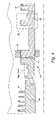
- FIG. 4 is a cross-sectional view of a turbine section in accordance with an exemplary embodiment of the present invention.
- FIG. 5 is a more detailed view of a part of the turbine section illustrated in FIG. 4 ;
- FIG. 6 is a cross-sectional view illustrating, inter alia, a more detailed view of a part of the turbine section illustrated in FIG. 4 ;
- FIG. 7 is a cross-sectional view illustrating, inter alia, a more detailed view of another part of the turbine section illustrated in FIG. 4 .
- FIGS. 4–7 illustrate a steam turbine in accordance with an exemplary embodiment.
- the steam turbine includes, for example, rotatable shaft 10 , oil deflector 30 , end packings 40 , bearings 42 and oil deflector 60 .
- shaft 10 includes an intermediate pressure (IP) rotor shaft portion 20 and a high pressure (HP) rotor shaft portion 50 .
- IP rotor shaft portion 20 includes stages 27 for holding buckets (not shown for clarity) upon which intermediate pressure steam is blown to rotate shaft 10 .
- HP rotor shaft portion 50 includes stages 57 for holding another set of buckets (not shown for clarity) upon which high pressure steam is blown to rotate shaft 10 .
- IP rotor shaft portion 20 and HP rotor shaft portion 50 are connected together at joint 43 .
- IP rotor shaft portion 20 includes an annular step 21 which projects radially from center portion 28 of shaft 10 .
- Step 21 includes a circumferential surface 22 which forms a radially outermost edge portion of step 21 .
- Circumferential surface 22 defines an oil slinger pocket 26 .
- Oil slinger pocket 26 forms an annular groove which allows oil to be trapped and collected for drainage.
- Step 21 also includes two side surfaces 23 and 25 extending in the radial direction away from central portion 28 .
- Surface 23 defines an annular groove 24 which is positioned radially underneath a portion of circumferential surface 22 .
- oil deflector 30 includes heat shields 33 , a set of seal rings 31 and another set of seal rings 32 .
- Heat shields 33 protect seal rings 31 and 32 from radiated heat transferred from end packings 40 .
- End packings 40 are designed to prevent steam from leaking toward other turbine components such as oil deflector 30 .
- Seal rings 31 and 32 each encircle a portion of step 21 of shaft 10 .
- Each of seal rings 31 and 32 has a radially innermost edge which is in close proximity to circumferential surface 22 of step 21 .
- a small working clearance is defined between the radially innermost edge of each of seal rings 31 and 32 and circumferential surface 22 which forms the radially outermost edge of step 21 .
- Seal rings 31 and 32 of oil deflector 30 provide a seal against oil leakage which travels axially along shaft 10 . Oil may begin leaking, for example, from bearing 42 and travel along shaft 10 .
- An annular chamber 34 is formed between the sets of seal rings 31 and 32 and opposite oil slinger pocket 26 so that the oil can be collected and drained.
- Step 21 provides a rotor geometry which prevents the overheating of oil in the area of oil deflector 30 .
- annular groove 24 reduces the amount of heat-conductive material that would otherwise form step 21 and thus diminishes the heat transferred to the area of rotor 10 near seal rings 31 and 32 through the heat conductive material forming shaft 10 .
- air flowing in groove 24 will cool step 21 and a part of central portion 28 which is close to groove 24 as shaft 10 rotates at a high speed. Rotor 10 , and hence the oil in the vicinity of rotor 10 and oil deflector 30 , will thus not be overheated.
- the temperature of the oil near oil deflector 30 is controlled to be less than 300° F. Oil carbonization near oil deflector 30 can therefore be prevented, thereby minimizing damage to shaft 10 and oil deflector 30 .
- HP rotor shaft portion 50 of shaft 10 includes a thrust bearing enclosure 55 and an annular step 51 which projects axially away from thrust bearing enclosure 55 (step 51 projects in the axial direction opposite of thrust bearing enclosure 55 ). Step 51 also extends radially away from central portion 58 of rotor shaft portion 50 .
- Step 51 includes a circumferential surface 52 which forms a radially outermost edge of step 51 .
- Circumferential surface 52 defines an oil slinger pocket 56 .
- Oil slinger pocket 56 forms an annular groove which allows oil to be trapped and collected for drainage.
- Step 51 also includes a side surface 53 extending in the radial direction away from central portion 58 .
- Surface 53 defines an annular groove 54 which is positioned radially underneath a portion of circumferential surface 52 .
- Oil deflector 60 includes heat shields 63 , a set of seal rings 61 and another set of seal rings 62 .
- Heat shields 63 protect seal rings 61 and 62 and other turbine components from radiated heat.
- Seal Rings 61 and 62 each encircle a portion of step 51 .
- Each of seal rings 61 and 62 has a radially innermost edge which is in close proximity to circumferential surface 52 .
- a small working clearance is defined between the radially innermost edge of each of seal rings 61 and 62 and circumferential surface 52 which forms the radially outermost edge of step 51 .
- Seal rings 61 and 62 of oil deflector 60 provide a seal against oil leakage which travels axially along shaft 10 .
- An annular chamber 64 formed between the sets of seal rings 61 and 62 and opposite to oil slinger pocket 56 collects oil so that it can be drained.
- Step 51 provides a rotor geometry which prevents the overheating of oil in the area of rotor 10 near oil deflector 60 . Oil carbonization in the area of oil deflector 60 can thus be prevented.
- annular groove 54 minimizes the amount of heat conductive material forming step 51 and thus diminishes the heat transferred to the area near seal rings 61 and 62 through the heat conductive material forming HP shaft portion 50 . Heat conductive material which is “missing” from step 51 to form annular groove 54 is thus not available to conduct heat.
- air flowing in groove 54 will cool step 51 and the part of central portion 58 which is close to groove 54 , particularly as shaft 10 rotates at a high speed.
- Rotor portion 50 and hence the oil in the vicinity of oil deflector 60 , will thus not be overheated.
- the temperature of the oil will remain below 300° F., the temperature needed for oil to carbonize. Oil carbonization near oil deflector 60 is thus prevented. Damage to shaft 10 and oil deflector 60 is therefore minimized.
- shaft 10 may include only one of steps 21 and 51 . That is, shaft 10 may include an IP rotor shaft portion 20 which includes step 21 and is connected to a HP rotor shaft portion 50 which does not include step 51 . Alternatively, shaft 10 may comprise HP rotor shaft portion 50 including step 51 and an IP rotor shaft portion 20 which does not include step 21 .
Landscapes
- Engineering & Computer Science (AREA)
- General Engineering & Computer Science (AREA)
- Mechanical Engineering (AREA)
- Turbine Rotor Nozzle Sealing (AREA)
- Sealing Devices (AREA)
Priority Applications (4)
| Application Number | Priority Date | Filing Date | Title |
|---|---|---|---|
| US10/709,203 US7056088B2 (en) | 2004-04-21 | 2004-04-21 | Steam turbine rotor temperature control at oil deflector |
| EP05252317A EP1589190A3 (de) | 2004-04-21 | 2005-04-14 | Kühlung eines Dampfturbinenrotor im Bereich des Öldeflektors |
| JP2005122014A JP2005307982A (ja) | 2004-04-21 | 2005-04-20 | 蒸気タービンのオイルデフレクタ位置におけるロータ温度制御 |
| CN2005100676087A CN1690486B (zh) | 2004-04-21 | 2005-04-21 | 蒸汽涡轮转子在油导流器附近的温度控制 |
Applications Claiming Priority (1)
| Application Number | Priority Date | Filing Date | Title |
|---|---|---|---|
| US10/709,203 US7056088B2 (en) | 2004-04-21 | 2004-04-21 | Steam turbine rotor temperature control at oil deflector |
Publications (2)
| Publication Number | Publication Date |
|---|---|
| US20050238485A1 US20050238485A1 (en) | 2005-10-27 |
| US7056088B2 true US7056088B2 (en) | 2006-06-06 |
Family
ID=34940816
Family Applications (1)
| Application Number | Title | Priority Date | Filing Date |
|---|---|---|---|
| US10/709,203 Expired - Fee Related US7056088B2 (en) | 2004-04-21 | 2004-04-21 | Steam turbine rotor temperature control at oil deflector |
Country Status (4)
| Country | Link |
|---|---|
| US (1) | US7056088B2 (de) |
| EP (1) | EP1589190A3 (de) |
| JP (1) | JP2005307982A (de) |
| CN (1) | CN1690486B (de) |
Cited By (1)
| Publication number | Priority date | Publication date | Assignee | Title |
|---|---|---|---|---|
| US20090050410A1 (en) * | 2007-08-22 | 2009-02-26 | Nathan Robert Berberich | Methods and systems for sealing rotating machines |
Families Citing this family (5)
| Publication number | Priority date | Publication date | Assignee | Title |
|---|---|---|---|---|
| EP3009610B1 (de) * | 2014-10-14 | 2020-11-25 | General Electric Technology GmbH | Dampfturbinenwellendichtungsanordnung |
| GB2534361A (en) * | 2015-01-16 | 2016-07-27 | Rolls Royce Plc | Assembly having a seal and a rotatable component |
| JP6380767B2 (ja) * | 2015-12-14 | 2018-08-29 | ドゥサン ヘヴィー インダストリーズ アンド コンストラクション カンパニー リミテッド | ベアリングオイル除去型ロータ構造 |
| KR101753026B1 (ko) | 2017-03-29 | 2017-07-11 | 두산중공업 주식회사 | 베어링 오일 제거 구조와 이를 포함하는 로터샤프트 및 터보머신 |
| FR3075252B1 (fr) * | 2017-12-14 | 2020-06-26 | Safran Aircraft Engines | Ensemble d'etancheite |
Citations (9)
| Publication number | Priority date | Publication date | Assignee | Title |
|---|---|---|---|---|
| US2846245A (en) * | 1954-07-09 | 1958-08-05 | Gen Electric | Oil deflector for shaft seal with forced ventilation |
| US3942804A (en) * | 1974-11-18 | 1976-03-09 | General Electric Co. | Turbomachine seal |
| US4350345A (en) * | 1981-04-01 | 1982-09-21 | General Electric Company | Air-sealed oil deflector |
| US4402514A (en) | 1981-09-10 | 1983-09-06 | General Electric Company | Fluid-cooled oil deflector |
| US5593274A (en) | 1995-03-31 | 1997-01-14 | General Electric Co. | Closed or open circuit cooling of turbine rotor components |
| US6158102A (en) | 1999-03-24 | 2000-12-12 | General Electric Co. | Apparatus and methods for aligning holes through wheels and spacers and stacking the wheels and spacers to form a turbine rotor |
| US6382903B1 (en) | 1999-03-03 | 2002-05-07 | General Electric Company | Rotor bore and turbine rotor wheel/spacer heat exchange flow circuit |
| US6397604B2 (en) | 1999-04-15 | 2002-06-04 | General Electric Company | Cooling supply system for stage 3 bucket of a gas turbine |
| US6481969B2 (en) | 1999-05-10 | 2002-11-19 | General Electric Company | Apparatus and methods for balancing turbine rotors |
Family Cites Families (6)
| Publication number | Priority date | Publication date | Assignee | Title |
|---|---|---|---|---|
| US1562019A (en) * | 1922-09-05 | 1925-11-17 | Gen Electric | Shaft packing for elastic-fluid turbines and the like |
| JPS55112002U (de) * | 1979-02-02 | 1980-08-06 | ||
| JPS55112002A (en) * | 1979-02-21 | 1980-08-29 | Mitsubishi Electric Corp | Reflecting mirror antenna |
| JPS5949702U (ja) * | 1982-09-24 | 1984-04-02 | 株式会社東芝 | 蒸気タ−ビンの油切り装置 |
| JP2756117B2 (ja) * | 1987-11-25 | 1998-05-25 | 株式会社日立製作所 | ガスタービンロータ |
| DE19543764A1 (de) * | 1995-11-24 | 1997-05-28 | Asea Brown Boveri | Berührungsdichtung für Strömungsmaschinen |
-
2004
- 2004-04-21 US US10/709,203 patent/US7056088B2/en not_active Expired - Fee Related
-
2005
- 2005-04-14 EP EP05252317A patent/EP1589190A3/de not_active Withdrawn
- 2005-04-20 JP JP2005122014A patent/JP2005307982A/ja active Pending
- 2005-04-21 CN CN2005100676087A patent/CN1690486B/zh not_active Expired - Fee Related
Patent Citations (10)
| Publication number | Priority date | Publication date | Assignee | Title |
|---|---|---|---|---|
| US2846245A (en) * | 1954-07-09 | 1958-08-05 | Gen Electric | Oil deflector for shaft seal with forced ventilation |
| US3942804A (en) * | 1974-11-18 | 1976-03-09 | General Electric Co. | Turbomachine seal |
| US4350345A (en) * | 1981-04-01 | 1982-09-21 | General Electric Company | Air-sealed oil deflector |
| US4402514A (en) | 1981-09-10 | 1983-09-06 | General Electric Company | Fluid-cooled oil deflector |
| US5593274A (en) | 1995-03-31 | 1997-01-14 | General Electric Co. | Closed or open circuit cooling of turbine rotor components |
| US6382903B1 (en) | 1999-03-03 | 2002-05-07 | General Electric Company | Rotor bore and turbine rotor wheel/spacer heat exchange flow circuit |
| US6158102A (en) | 1999-03-24 | 2000-12-12 | General Electric Co. | Apparatus and methods for aligning holes through wheels and spacers and stacking the wheels and spacers to form a turbine rotor |
| US6438837B1 (en) | 1999-03-24 | 2002-08-27 | General Electric Company | Methods for aligning holes through wheels and spacers and stacking the wheels and spacers to form a turbine rotor |
| US6397604B2 (en) | 1999-04-15 | 2002-06-04 | General Electric Company | Cooling supply system for stage 3 bucket of a gas turbine |
| US6481969B2 (en) | 1999-05-10 | 2002-11-19 | General Electric Company | Apparatus and methods for balancing turbine rotors |
Cited By (2)
| Publication number | Priority date | Publication date | Assignee | Title |
|---|---|---|---|---|
| US20090050410A1 (en) * | 2007-08-22 | 2009-02-26 | Nathan Robert Berberich | Methods and systems for sealing rotating machines |
| US8256575B2 (en) | 2007-08-22 | 2012-09-04 | General Electric Company | Methods and systems for sealing rotating machines |
Also Published As
| Publication number | Publication date |
|---|---|
| US20050238485A1 (en) | 2005-10-27 |
| EP1589190A3 (de) | 2013-01-16 |
| CN1690486A (zh) | 2005-11-02 |
| CN1690486B (zh) | 2010-12-22 |
| EP1589190A2 (de) | 2005-10-26 |
| JP2005307982A (ja) | 2005-11-04 |
Similar Documents
| Publication | Publication Date | Title |
|---|---|---|
| US7878757B2 (en) | Centrifugal water pump | |
| JP3702212B2 (ja) | 軸シール機構及びタービン | |
| US7052240B2 (en) | Rotating seal arrangement for turbine bucket cooling circuits | |
| JP3567065B2 (ja) | ガスタービン | |
| US5087176A (en) | Method and apparatus to provide thermal isolation of process gas bearings | |
| CN102213117B (zh) | 轴密封部 | |
| EP0760053B1 (de) | Ringförmiges lagergehäuse | |
| EP1116906A2 (de) | Dichtungsanordnung | |
| KR100854193B1 (ko) | 시일 및 증기 글랜드 | |
| EP2350503A1 (de) | Hydrodynamisches rundumversiegelungssystem für sehr grosse getriebe | |
| CN1360660A (zh) | 带有转子密封系统的流体机械,尤其是燃气轮机 | |
| KR102095667B1 (ko) | 시일 장치 및 회전 기계 | |
| US20160097293A1 (en) | Compressor seal assembly for a turbocharger | |
| US20080001363A1 (en) | Brush sealing system and method for rotary machines | |
| US6821086B1 (en) | Turbomachine seal assembly and method therefor | |
| US7056088B2 (en) | Steam turbine rotor temperature control at oil deflector | |
| JP4688448B2 (ja) | 回転シール | |
| US6761530B1 (en) | Method and apparatus to facilitate reducing turbine packing leakage losses | |
| JP5902143B2 (ja) | シャフトシール | |
| JP2005163641A (ja) | ターボチャージャ | |
| US6688847B2 (en) | Shaft structure and bearing structure for tail end of rotor of gas turbine | |
| JP4115081B2 (ja) | 軸封装置 | |
| JPH11229804A (ja) | 蒸気冷却ガスタービン | |
| JP2004316509A (ja) | タービン車室のシール構造 | |
| GB2452040A (en) | Brush sealing system using carbon bristles for use with rotary machines |
Legal Events
| Date | Code | Title | Description |
|---|---|---|---|
| AS | Assignment |
Owner name: GENERAL ELECTRIC COMPANY, NEW YORK Free format text: ASSIGNMENT OF ASSIGNORS INTEREST;ASSIGNORS:RIVAS, FLOR DEL CARMEN;PALMER, GENE DAVID;LAVASH, JOHN CLELAND;REEL/FRAME:014518/0133;SIGNING DATES FROM 20040405 TO 20040406 |
|
| FEPP | Fee payment procedure |
Free format text: PAYOR NUMBER ASSIGNED (ORIGINAL EVENT CODE: ASPN); ENTITY STATUS OF PATENT OWNER: LARGE ENTITY |
|
| FPAY | Fee payment |
Year of fee payment: 4 |
|
| FPAY | Fee payment |
Year of fee payment: 8 |
|
| FEPP | Fee payment procedure |
Free format text: MAINTENANCE FEE REMINDER MAILED (ORIGINAL EVENT CODE: REM.) |
|
| LAPS | Lapse for failure to pay maintenance fees |
Free format text: PATENT EXPIRED FOR FAILURE TO PAY MAINTENANCE FEES (ORIGINAL EVENT CODE: EXP.) |
|
| STCH | Information on status: patent discontinuation |
Free format text: PATENT EXPIRED DUE TO NONPAYMENT OF MAINTENANCE FEES UNDER 37 CFR 1.362 |
|
| FP | Lapsed due to failure to pay maintenance fee |
Effective date: 20180606 |