US7038781B2 - Time correlation of ultrafast laser pulses - Google Patents
Time correlation of ultrafast laser pulses Download PDFInfo
- Publication number
- US7038781B2 US7038781B2 US10/676,679 US67667903A US7038781B2 US 7038781 B2 US7038781 B2 US 7038781B2 US 67667903 A US67667903 A US 67667903A US 7038781 B2 US7038781 B2 US 7038781B2
- Authority
- US
- United States
- Prior art keywords
- pulse
- detector
- pulses
- response
- temporal overlap
- Prior art date
- Legal status (The legal status is an assumption and is not a legal conclusion. Google has not performed a legal analysis and makes no representation as to the accuracy of the status listed.)
- Expired - Lifetime, expires
Links
- 238000000034 method Methods 0.000 claims abstract description 47
- 230000004044 response Effects 0.000 claims abstract description 40
- 230000002123 temporal effect Effects 0.000 claims abstract description 39
- 230000003287 optical effect Effects 0.000 claims description 26
- 230000001419 dependent effect Effects 0.000 claims description 7
- 230000008859 change Effects 0.000 claims description 6
- 230000003111 delayed effect Effects 0.000 abstract description 2
- 230000001360 synchronised effect Effects 0.000 abstract 1
- 238000000926 separation method Methods 0.000 description 9
- 230000000694 effects Effects 0.000 description 7
- 238000010586 diagram Methods 0.000 description 5
- 238000012545 processing Methods 0.000 description 5
- 238000010408 sweeping Methods 0.000 description 4
- 238000002082 coherent anti-Stokes Raman spectroscopy Methods 0.000 description 3
- 238000012937 correction Methods 0.000 description 3
- 230000003247 decreasing effect Effects 0.000 description 3
- 239000007787 solid Substances 0.000 description 3
- 230000001934 delay Effects 0.000 description 2
- 238000013519 translation Methods 0.000 description 2
- 230000001960 triggered effect Effects 0.000 description 2
- 230000005374 Kerr effect Effects 0.000 description 1
- 238000004458 analytical method Methods 0.000 description 1
- 230000008901 benefit Effects 0.000 description 1
- 238000012512 characterization method Methods 0.000 description 1
- 230000001427 coherent effect Effects 0.000 description 1
- 238000013480 data collection Methods 0.000 description 1
- 230000007423 decrease Effects 0.000 description 1
- 238000013461 design Methods 0.000 description 1
- 238000001514 detection method Methods 0.000 description 1
- 238000003745 diagnosis Methods 0.000 description 1
- 239000006185 dispersion Substances 0.000 description 1
- 238000006073 displacement reaction Methods 0.000 description 1
- 238000002474 experimental method Methods 0.000 description 1
- 238000009532 heart rate measurement Methods 0.000 description 1
- 238000003384 imaging method Methods 0.000 description 1
- 230000003993 interaction Effects 0.000 description 1
- 230000008569 process Effects 0.000 description 1
- 230000000750 progressive effect Effects 0.000 description 1
- 238000004611 spectroscopical analysis Methods 0.000 description 1
- 238000012546 transfer Methods 0.000 description 1
Images


Classifications
-
- G—PHYSICS
- G01—MEASURING; TESTING
- G01J—MEASUREMENT OF INTENSITY, VELOCITY, SPECTRAL CONTENT, POLARISATION, PHASE OR PULSE CHARACTERISTICS OF INFRARED, VISIBLE OR ULTRAVIOLET LIGHT; COLORIMETRY; RADIATION PYROMETRY
- G01J11/00—Measuring the characteristics of individual optical pulses or of optical pulse trains
-
- H—ELECTRICITY
- H01—ELECTRIC ELEMENTS
- H01S—DEVICES USING THE PROCESS OF LIGHT AMPLIFICATION BY STIMULATED EMISSION OF RADIATION [LASER] TO AMPLIFY OR GENERATE LIGHT; DEVICES USING STIMULATED EMISSION OF ELECTROMAGNETIC RADIATION IN WAVE RANGES OTHER THAN OPTICAL
- H01S3/00—Lasers, i.e. devices using stimulated emission of electromagnetic radiation in the infrared, visible or ultraviolet wave range
- H01S3/10—Controlling the intensity, frequency, phase, polarisation or direction of the emitted radiation, e.g. switching, gating, modulating or demodulating
- H01S3/10053—Phase control
-
- H—ELECTRICITY
- H01—ELECTRIC ELEMENTS
- H01S—DEVICES USING THE PROCESS OF LIGHT AMPLIFICATION BY STIMULATED EMISSION OF RADIATION [LASER] TO AMPLIFY OR GENERATE LIGHT; DEVICES USING STIMULATED EMISSION OF ELECTROMAGNETIC RADIATION IN WAVE RANGES OTHER THAN OPTICAL
- H01S3/00—Lasers, i.e. devices using stimulated emission of electromagnetic radiation in the infrared, visible or ultraviolet wave range
- H01S3/10—Controlling the intensity, frequency, phase, polarisation or direction of the emitted radiation, e.g. switching, gating, modulating or demodulating
- H01S3/105—Controlling the intensity, frequency, phase, polarisation or direction of the emitted radiation, e.g. switching, gating, modulating or demodulating by controlling the mutual position or the reflecting properties of the reflectors of the cavity, e.g. by controlling the cavity length
-
- H—ELECTRICITY
- H01—ELECTRIC ELEMENTS
- H01S—DEVICES USING THE PROCESS OF LIGHT AMPLIFICATION BY STIMULATED EMISSION OF RADIATION [LASER] TO AMPLIFY OR GENERATE LIGHT; DEVICES USING STIMULATED EMISSION OF ELECTROMAGNETIC RADIATION IN WAVE RANGES OTHER THAN OPTICAL
- H01S3/00—Lasers, i.e. devices using stimulated emission of electromagnetic radiation in the infrared, visible or ultraviolet wave range
- H01S3/10—Controlling the intensity, frequency, phase, polarisation or direction of the emitted radiation, e.g. switching, gating, modulating or demodulating
- H01S3/106—Controlling the intensity, frequency, phase, polarisation or direction of the emitted radiation, e.g. switching, gating, modulating or demodulating by controlling devices placed within the cavity
-
- H—ELECTRICITY
- H01—ELECTRIC ELEMENTS
- H01S—DEVICES USING THE PROCESS OF LIGHT AMPLIFICATION BY STIMULATED EMISSION OF RADIATION [LASER] TO AMPLIFY OR GENERATE LIGHT; DEVICES USING STIMULATED EMISSION OF ELECTROMAGNETIC RADIATION IN WAVE RANGES OTHER THAN OPTICAL
- H01S3/00—Lasers, i.e. devices using stimulated emission of electromagnetic radiation in the infrared, visible or ultraviolet wave range
- H01S3/10—Controlling the intensity, frequency, phase, polarisation or direction of the emitted radiation, e.g. switching, gating, modulating or demodulating
- H01S3/13—Stabilisation of laser output parameters, e.g. frequency or amplitude
- H01S3/139—Stabilisation of laser output parameters, e.g. frequency or amplitude by controlling the mutual position or the reflecting properties of the reflectors of the cavity, e.g. by controlling the cavity length
- H01S3/1394—Stabilisation of laser output parameters, e.g. frequency or amplitude by controlling the mutual position or the reflecting properties of the reflectors of the cavity, e.g. by controlling the cavity length by using an active reference, e.g. second laser, klystron or other standard frequency source
-
- H—ELECTRICITY
- H01—ELECTRIC ELEMENTS
- H01S—DEVICES USING THE PROCESS OF LIGHT AMPLIFICATION BY STIMULATED EMISSION OF RADIATION [LASER] TO AMPLIFY OR GENERATE LIGHT; DEVICES USING STIMULATED EMISSION OF ELECTROMAGNETIC RADIATION IN WAVE RANGES OTHER THAN OPTICAL
- H01S3/00—Lasers, i.e. devices using stimulated emission of electromagnetic radiation in the infrared, visible or ultraviolet wave range
- H01S3/23—Arrangements of two or more lasers not provided for in groups H01S3/02 - H01S3/22, e.g. tandem arrangements of separate active media
- H01S3/2383—Parallel arrangements
Definitions
- the present invention relates generally to measuring characteristics of ultrafast laser pulses by auto-correlation and cross-correlation of pulses from modelocked ultrafast lasers.
- the invention relates in particular to auto and cross-correlation methods in which the temporal overlap of pulses or pulse components on a single two-photon detector is varied by varying the phase of pulse trains emitted by two lasers or the frequency of a pulse train emitted by one laser.
- Ultrafast lasers can deliver very short (ultrafast) pulses at relatively high pulse repetition rates.
- pulses may have a duration of 10 picoseconds (ps) or less at pulse repetition rates between about 75 Megahertz (MHz) and 1 Gigahertz (GHz) or greater.
- the pulse duration of a passively modelocked laser is determined, inter alia, by the gain-medium in the resonator and the method of passive modelocking.
- the pulse repetition rate of a passively modelocked laser is determined by the optical length of the resonator of the laser.
- ultrafast laser pulses such as time-resolved coherent anti-Stokes Raman spectroscopy (CARS) and CARS imaging studies
- diagnosis of the ultrafast pulses is required.
- conventional optical detectors such as photodiode-detectors, become less able to provide a signal that gives an accurate representation of the amplitude and duration of the pulses. Simply stated, this is because the length of time it takes a detector to respond to the pulse is greater than the duration of the pulse.
- pulse measurement techniques based on correlation of two pulses have been extensively developed.
- what is measured is a signal provided by observing an effect produced in a detecting medium that is produced when the medium receives two pulses simultaneously.
- the phase of one of the pulses is progressively changed with respect to the other.
- the effect to be observed (detected) is at a minimum when the pulses only just overlap in time and at a maximum when the pulses exactly overlap, i.e., are exactly in phase.
- Numerical analysis techniques are used to extract pulse characterization data from signals representing the magnitude of the observed effect as a function of phase.
- Correlation techniques may be divided into autocorrelation techniques and cross-correlation techniques.
- auto correlation the two pulses to be progressively overlapped are created by optically dividing a single pulse into two components.
- One of the pulse components is sent along a fixed optical path to the two-pulse detecting medium and the other is sent via another optical path of a variably different length from the length of the fixed optical path. Variation of this path length is used to vary the time between arrival of the pulse components at the detecting medium.
- cross-correlation each of the two pulses is supplied by a separate laser. Pulses from one of the lasers travels to the detecting medium via a fixed path. Pulses from the other lasers travel to the detecting medium via a variable path.
- a cross-correlation method for laser pulses comprises providing two repetitively pulsed laser resonators each delivering a pulse train.
- the pulse trains are directed such that they to spatially overlap on a detector.
- the detector provides a response when a pulse of one of the pulse trains temporally overlaps a pulse of the second pulse train.
- the detector response has a magnitude dependent on the degree of temporal overlap of the pulses.
- the optical length of one of the laser resonators is varied to change the temporal overlap between the pulses.
- the magnitude of the response of the detector is recorded at a plurality of different degrees of temporal overlap of the pulses.
- Optical characteristics of the pulses can be determined from data representing the magnitude of the detector response as a function of the temporal overlap.
- an auto-correlation method for laser pulses comprises providing a repetitively pulsed laser resonator delivering a train of pulses having a selectively variable pulse repetition frequency.
- Each pulse of the pulse train is optically divided into two pulse components.
- Each pulse component is directed along a different-length path to the detector.
- the detector provides a response when a pulse component received from one of the paths temporally overlaps a pulse component received from the other pulse component on said detector.
- the detector response has a magnitude dependent on the degree of temporal overlap of the pulse components.
- the pulse repetition frequency is selectively varied while maintaining the path lengths fixed. This correspondingly varies the temporal overlap of the pulse components.
- the magnitude of the response of the detector at a plurality of different degrees of temporal overlap of the pulse components is recorded to provide data from which characteristics of the pulses can be determined.
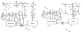
- FIG. 1 schematically illustrates a preferred embodiment of apparatus for implementing a cross correlation method in accordance with the present invention including two repetitively pulsed lasers, pulses of which are directed to a single detector, with one the lasers being provided with a phase controller arranged to control one the lasers with reference to the other to provide a varying temporal overlap of pulses at the detector.
- FIG. 2 is a block diagram schematically illustrating one preferred example of a phase controller suitable for use as the phase controller of FIG. 1 .
- FIG. 3 schematically illustrates of one preferred arrangement of electronic circuits and their interconnection in the digital phase detector of FIG. 2 , including two flip-flop circuit elements arranged to be triggered to a high logic state on receipt of a electronic pulse corresponding to a laser pulse and a logic AND gate arranged to reset both flip-flop circuits to a low logic state after each has received an electronic pulse corresponding to a laser pulse.
- FIGS. 4A–D are timing diagrams indicating the form of output pulse trains from the flip-flop circuits of FIG. 3 in response to the flip-flop circuits receiving electronic pulse trains of different frequency.
- FIGS. 5A–D are timing diagrams indicating the form of output pulse trains from the flip-flop circuits of FIG. 3 in response to the flip-flop circuits receiving electronic pulse trains of the same frequency but different phase.
- FIGS. 6A and 6B are graphs schematically illustrating temporally overlapping pulse pairs having different temporal separation at the detector of FIG. 1 and the response of the detector to the overlapping pulse pairs.
- FIG. 7 schematically illustrates a preferred embodiment of apparatus for implementing an auto-correlation method in accordance with the present invention including only one repetitively pulsed laser, the pulses of which are divided into two components, with the components following paths of different length the and being directed to a single detector, the laser being provided with a frequency controller arranged to vary the pulse repetition frequency to varying temporal overlap of pulse components at the detector.
- FIGS. 8A and 8B are graphs schematically illustrating temporally overlapping pulse components having different temporal separation at the detector of FIG. 7 and the response of the detector to the overlapping pulse components.
- FIG. 1 schematically illustrates a preferred apparatus 10 for implementing a cross-correlation method in accordance with the present invention.
- Apparatus 10 includes two lasers 12 and 14 , and a phase (and frequency) controller 11 for synchronizing the output of the lasers.
- FIG. 2 schematically illustrates the functional layout of a preferred example of a phase controller 11 including a digital phase detector 16 .
- FIG. 3 schematically illustrates electronic circuits and their interconnection in digital phase detector 16 .
- the paths of laser pulses in and from the lasers are designated by fine lines, and the direction of propagation of the laser pulses is indicated by open arrows. Connections between electronic circuits and electronic function blocks are indicated in FIG. 1 and FIG. 2 by bold lines, with the direction of signal transfer between the circuits and blocks indicated by solid arrows.
- Laser 12 may be referred to as the master laser and includes a resonator 18 terminated by a maximally reflecting mirror 20 and a partially transmitting (outcoupling) mirror.
- Mirror 22 is mounted on a translation stage 24 that allows mirror 22 to be moved axially, as indicated by arrows A, for providing coarse adjustment of the optical length of the resonator, and, accordingly, coarse adjustment of the repetition-frequency of laser pulses delivered from the resonator.
- Laser 14 may be referred to as the slave laser and includes a resonator 26 terminated by a maximally reflecting mirror 20 and a partially transmitting (outcoupling) mirror 22 .
- Mirror 22 of laser 14 is also mounted on a translation stage 24 that allows mirror 22 to be moved axially for providing coarse adjustment of the resonator length.
- the optical length of resonator 26 is arranged to be automatically adjusted by digital phase detector 16 and associated electronic circuits and devices for synchronizing output pulse trains delivered by laser 14 with output pulse trains delivered by laser 12 .
- a first of these is a galvanometer arrangement 28 including two transparent plates 32 and 36 that are rotatable as indicated by arrows B. The plates are rotated toward or away from each other for respectively increasing or decreasing the resonator length. The rotational position is determined by a galvanometer driver circuit 38 .
- Galvanometer 28 provides for medium range adjustment of the resonator length (and pulse-repetition frequency).
- the second length resonator-length-adjustment device is a piezoelectric transducer (PZT) 40 which positions mirror 20 of resonator 26 axially as indicated by arrows A.
- PZT piezoelectric transducer
- the axial position mirror 20 is determined by the magnitude of a voltage applied to the PZT by a driver circuit 42 .
- PZT 40 provides for rapid-response, fine adjustment of the optical length of resonator 26 .
- Resonators 18 and 26 each include a gain-medium 44 and an aperture 46 that works cooperatively with a Kerr effect in gain-medium 44 to provide passive modelocking of the resonators.
- resonator length refers to the optical length of the resonator.
- the optical length may be different from the physical length due to the length and refractive index of optical components in the resonator.
- the optical length of the resonator can be changed by moving the mirrors, in which case the physical length is also changed or by rotating plates 32 and 36 , in which case the optical length can be changed without changing the physical length.
- lasers 12 and 14 are depicted for simplicity of illustration, with straight resonators in a very basic form. Those skilled in the art will recognize that ultrafast lasers often have complex folded resonators and include tuning elements and elements for controlling group delay dispersion (GDD) such as prisms. A detailed discussion of such features is not necessary for understanding principles of the present invention. Accordingly such features are not described or depicted herein.
- GDD group delay dispersion
- Galvanometer 28 is arranged for particular use in a straight resonator. Those skilled in that art will recognize that other galvanometer arrangements may be used in straight or folded resonators without departing from the spirit and scope of the present invention.
- Output pulse trains from lasers 12 and 14 are delivered along paths 45 and 47 and are focused by a lens 50 to spatially overlap on a detector 51 .
- Detector 51 is arranged to respond only when two pulses are incident thereon, overlapping in space and time.
- One preferred detector is a two-photon effect light-emitting-diode (LED) type detector available from Hamamatsu Corporation of Japan.
- Paths 45 and 47 may be of different optical length and include optical components such as turning mirrors 49 .
- pulses traveling along each path arrive on detector 51 with the same repetition frequency and in a selectively variable phase relationship with each other.
- the phase relationship is varied such that pulses arrive with different degrees of temporal overlap.
- the magnitude of the detector output for different overlaps is recorded by a data processing computer 90 .
- the phase difference is interpreted as time. i.e., as a fraction of a pulse repetition interval to provide time versus magnitude data from which the pulse characteristics can be derived by any well know method used in prior-art, variable delay line cross-correlation techniques.
- the time is translated in physical movement of mirror 20 via PZT 40 .
- the range of the phase change required to pass through a range of overlap is determined by the rate of driving the PZT.
- a 100 picosecond sweeping range at 30 Hz can be achieved by displacement of only tens of nanometers by PZT 40 . This sweeping rate enables a relatively fast data acquisition rate thereby avoiding low frequency noise interference in the data collection.
- Mirror 22 of laser resonator 14 is preferably driven by a stepping motor (not shown) controlled by a frequency controller 17 in phase controller 11 (see FIG. 2 ), and adjusted such that lasers 12 and 14 have pulse repetition frequencies matched to within about 1.0%.
- This adjustment can be monitored by a pulse counter arrangement or the like (not shown) in frequency controller.
- This adjustment brings the repetition frequency difference of lasers 12 and 14 within a range that can be more precisely corrected by galvanometer device 28 .
- Galvanometer device 28 automatically reduces the repetition frequency difference to within a range that can be automatically corrected by PZT-driven mirror 20 of resonator 26 .
- a preferred method of automatically effecting these corrections (frequency and phase synchronization or matching) is set forth below with continuing with reference to FIG. 1 .
- a portion of pulse trains from lasers 12 and 14 is sampled by beamsplitter mirrors 52 and 54 respectively.
- the sampled portions are directed to photodetectors (here photodiodes) 56 and 58 respectively.
- the output of photodiodes 56 and 58 is communicated to digital receivers 60 and 62 respectively.
- Digital receivers 60 and 62 ( FIG. 2 ) deliver a pulse at a predetermined peak logic voltage level for each electronic pulse received from the photodiodes independent of the magnitude of the received pulses. Accordingly, digital receivers 60 and 62 deliver digital signals (trains of electronic pulses all having the same peak voltage) S 1 and S 2 to digital phase detector 16 . Signals S 1 and S 2 have the same repetition frequency as the pulse-repetition frequency of laser pulse trains arriving at photodiodes 56 and 58 respectively.
- Digital phase detector 16 (see FIG. 2 ) is arranged to generate an analog voltage signal V 1 from digital signals S 1 and S 2 using circuitry described in detail further hereinbelow.
- Analog voltage V 1 is representative of the phase difference between signals S 1 and S 2 and will be essentially zero when signals S 1 and S 2 have the same repetition frequency and are in phase. It will be evident to one skilled in the art that, because of the above discussed frequency jitter, the length of resonator 26 will usually be in a constant state of correction. Accordingly, voltage V 1 may only instantaneously be exactly zero and, when synchronization has been effected to a limiting accuracy of the inventive method and apparatus, may vary randomly with time slightly above and below zero. In this state, signal voltage V 1 can be referred to as being minimized, i.e., jittering about zero.
- voltage V 1 when voltage V 1 is zero, this indicates that sampled pulse trains are arriving in phase, at the same frequency at photo diodes 56 and 58 . Corresponding pulse trains arriving at detector 51 will have the same frequency but may be out of phase, having followed different paths of different length to the detector.
- voltage V 1 is summed with a voltage V 2 in a summer circuit 64 to provide an analog voltage signal V 3 .
- Voltage V 2 is selected such that V 3 is minimized when pulse trains from laser 12 and 14 arrive on detector 51 with the same repetition frequency and have the desired phase relationship with each other.
- sample pulse trains arriving at photodetectors 58 and 56 may not be in phase, and voltage V 1 , correspondingly, may not be zero.
- Selection of V 2 can be made by observing the arrival of pulses at the detector location, for example, using a phase detection arrangement similar to that described herein or by observing a phenomenon resulting from interaction of pulses with the detector.
- Voltage signal V 3 provides an error signal representative of a difference in frequency or desired phase.
- the signal is electronically filtered in a filter 66 to eliminate any high harmonic content.
- the filtered signal is communicated to PZT driver 42 and galvanometer driver 38 .
- the error signal will be zero if V 3 is zero.
- galvanometer 28 or PZT 40 will adjust the length of resonator 26 to synchronize the arrival of pulses at detector 51 . Depending on whether V 3 is positive or negative, the resonator length will be increased or decreased.
- PZT 40 has a response time about 500 times faster than that of galvanometer 28 . If PZT 40 reaches one or the other extreme of its range and V 3 is not zero, as may happen in an initial stage of synchronization, the PZT will wait at this extreme until galvanometer 28 has adjusted the resonator length sufficiently to drive V 3 to zero. Galvanometer 28 has a higher gain than PZT 40 and will tend to dominate the correction process at slow speeds leaving PZT 40 at about the midpoint of its movement range. If, subsequently, a length adjustment necessary to drive V 3 to zero is within the range of PZT 40 , as will typically be the case once initial synchronization has been achieved, PZT 40 will effect the length adjustment before galvanometer 28 can effectively respond.
- an important aspect of the present invention is the generation of an analog voltage signal V 1 from digital signals S 1 and S 2 having the pulse repetition frequency pulse trains delivered by lasers 12 and 14 respectively.
- Voltage V 1 is zero if signals S 1 and S 2 have the same pulse repetition frequency and are in phase at photodiodes 56 and 58 .
- V 1 has some other positive or negative value if signals S 1 and S 2 have different frequencies, or have the same frequency but are out of phase at the photodiodes.
- a preferred circuit layout and method of operation for digital phase detector 16 is discussed below with reference to FIG. 3 and FIGS. 4A–D .
- Digital phase detector 16 includes two flip-flop circuit elements (flip-flops) 70 and 72 . Each flip-flop has a logic voltage (LOGIC HI) applied to a port D thereof. Signals S 1 and S 2 are delivered to the clock port (CLK) of flip-flops 70 and 72 respectively. In the following discussion, signal S 1 and signals generated therefrom are occasionally referred to as master signals. Signal S 2 and signals generated therefrom are referred to as slave signals.
- LOGIC HI logic voltage
- CLK clock port
- the outputs of flip-flops 70 and 72 are both connected to a logic AND-gate 74 .
- the output of AND-gate 74 is asserted and the output of both flip-flops is reset to a low logic state after some minimal delay period (Td) due to response time of the logic gates.
- Td some minimal delay period
- the output (S 3 ) of the flip-flop 70 has a pulse width Td equal to the gate (switching) delays
- the output (S 4 ) of flip-flop 72 has a pulse width Ts+Td equal to the sum of the lead-time of the slave pulse and the gate delays.
- Ts is variable with phase and T D is a constant dependent on the particular electronic circuits used.
- Signals S 3 and S 4 are averaged over the period of the signal by low-pass filters 76 and 78 , respectively, to provide analog voltages V S1 and V S2 , respectively.
- the duty-cycle is equal to the pulse width times the frequency.
- the analog voltage delivered by each low-pass filter accordingly, is equal to the duty-cycle times the logic peak-to-peak voltage (V logic ) plus any offset voltage (V offset ) due to emitter-coupled logic (ECL) logic levels.
- Voltages V S1 and V S2 can be defined as indicated in equations (1) and (2) below.
- V S1 V logic *f S1 *( Ts+Td )+ V offset
- V S2 V logic *f S2 *Td+V offset
- Voltages V S1 and V S2 are subtracted in a differential amplifier 80 , the output of which is voltage V 1 discussed above with reference to FIG. 2 .
- T S the value of T S will vary with time and may vary periodically from zero and an entire period. In FIG. 4D this variation is greatly exaggerated for purposes of illustration.
- FIGS. 5A–D are timing diagrams illustrating a case where signals S 1 and S 2 have the same frequency but are out of phase.
- Equation (3) is a reasonable approximation in most practical instances of phase difference between the master and slave signals.
- phase difference in degrees
- Ts lead-time
- equation (3) can be rewritten as follows.
- V 1 (Phase* V logic *G )/360 (4)
- the output V 1 of digital phase detector 16 can be considered to be a variable representative only of the relative phase at photodiodes 56 and 58 of pulse trains emitted by lasers 12 and 14 .
- a phase difference at any instant can be the result of a frequency difference, or a phase difference only. If the slave signal lags the master in phase, voltage S 3 will be bigger than voltage S 4 . Accordingly the sign (positive or negative) of V 3 can be used to determine whether the length of resonator 26 should be increased by galvanometer 28 or PZT 40 .
- lasers 12 and 14 are first closely matched in frequency, for example, to within about 1%, by manual adjustment of resonator mirror 22 in one or both of the lasers.
- Voltage V 2 is set to zero, thereby making V 3 equal to V 1 , and automatic synchronization in accordance with the present invention (minimizing V 3 , here, also minimizing V 1 ) is implemented to equalize the frequency of pulse trains from the lasers and bring them in phase at photodiodes 56 and 58 .
- V 2 is then varied and V 3 minimized by the inventive automatic resonator length adjustment until the pulse trains have the desired phase relationship on detector 51 .
- V 2 can be set initially at some arbitrary value other than zero, and the frequency of the pulse trains matched without regard to their phase relationship. V 2 may then be varied and V 3 minimized until the desired phase relationship of the pulse trains at the detector is established. If V 2 has been predetermined, it can be set before automatic frequency matching is initiated, and the desired phase relationship will be established when V 3 is minimized by the automatic matching.
- V 2 is progressively incremented (or decremented) to preferably pass though a full range of pulse overlap in response to an input signal (sweep signal) that can be delivered from data processing computer 90 or from a separate computer (not shown).
- the voltage increment is interpreted as an increment in phase, which in turn can be interpreted as an increment in time from the instantly established pulse-repetition frequency. This may be done by either phase controller 11 , data processing computer 90 , or even the separate computer, but the interpreted data must be made available to compute 90 for data processing.
- FIG. 6A and FIG. 6B are graphs schematically illustrating effects of temporal pulse overlap on the response of detector 51 .
- pulses out of the pulse trains traveling on paths 45 and 47 are shown respectively as dashed and solid curves.
- an initial pulse-pair has a phase difference (time separation) ⁇ 1 (pulse 45 lagging in phase) produces no response in detector 51 ( FIG. 6B ).
- the phase and time separation is then incremented to provide pulse-pairs having separations ⁇ 2 , ⁇ 3 , ⁇ 4 , ⁇ 3 , ⁇ 2 .
- These pulse pairs produce responses 92 , 93 , 94 , 95 , and 96 , respectively, in detector 51 .
- Apparatus 98 includes only one repetitively pulsed, modelocked ultrafast laser, here laser 14 is automatically adjustable as described above with reference to apparatus 10 of FIG. 1 .
- a train of pulses leaves laser 14 and travel along path 47 via turning mirrors 49 .
- Each pulse in the train is optically divided into two component pulses by a beamsplitter 102 .
- One component pulse travels a relatively short path 47 A focused by lens 50 onto detector 51 .
- the other component travels via an optical delay path 47 B including turning mirrors 104 and focused by lens 50 onto detector 51 .
- the difference in path length between paths 47 A and 47 B is about twice the longest length of resonator 26 of laser 14 .
- the difference in path length between paths 47 A and 47 B is selected such that, at a pulse repetition frequency within the available range of frequencies of laser 14 , it is possible to exactly temporally overlap a delayed (path 47 B) component of an Nth pulse in the train arriving at beamsplitter 102 on path 47 with an undelayed (path 46 B) component of the (N+1)th, i.e., the next, pulse in the train. Then, with the delay path length fixed, as the pulse repetition frequency is increased or decreased then overlap of the pulse components will become less exact until there is not any pulse-overlap at all, and accordingly, not any response from detector 51 .
- An auto-correlation overlap-scan can be performed as described above for a cross-correlation scan with an exception that it is the pulse repetition frequency of the one laser (laser 14 ) that is scanned or swept (with the delay path 47 B fixed) rather than the phase between two laser each providing a pulse train.
- the sweeping is controlled by a frequency sweep signal provided to a detector (photodiode) 58 and frequency controller 100 compares this with the frequency requested by the sweep signal and operates one or both of PZT 40 and device 28 to adjust the length of resonator 26 to establish the desired pulse repetition frequency.
- the length of the resonator can be varied continuously or incrementally as would be known to one of ordinary skill in the art.
- FIG. 8A and FIG. 8B are graphs schematically illustrating effects of temporal pulse-component overlap on the response of detector 51 resulting from a frequency sweep in apparatus 98 .
- pulses (out of a pulse trains) traveling on paths 47 A and 47 B are shown respectively as dashed and solid curves.
- an initial pulse-pair has a time separation ⁇ 1 (pulse 45 lagging in phase) produces no response in detector 51 ( FIG. 6B ).
- the phase and time separation is then incremented to provide pulse-pairs having separations ⁇ 2 , ⁇ 3 , ⁇ 4 , ⁇ 3 , ⁇ 2 .
- pulse pairs produce responses 111 , 112 , 113 , 114 , and 115 , respectively, in detector 51 .
- the pulse separation times are the differences between the pulse repetition interval at the instant frequency scan increment and the pulse repetition interval for the frequency at which the pulse components overlap.
- Auto-correlation capability in apparatus 98 has an advantage over prior-art auto-correlation apparatus inasmuch as no physical scanning optical delay line including moving components is required. Absence of moving components provides that optical stability is achievable even in a relatively long delay line.
- a 10 Hz frequency sweep rate for a delay range of 10 picoseconds enables low noise data acquisition by avoiding low frequency noise as discussed above with reference to apparatus 10 .
- path delay path 47 B is described as being held fixed during a frequency scan, the path may be made selectively adjustable to allow it to be made compatible with a number of pulse-component overlap frequencies.
- cross-correlation apparatus 10 FIG.
- phase and frequency controller 100 is described herein with reference to preferred embodiment of a phase and frequency controller other configurations of phase and frequency controller may be used without departing from the spirit and scope of the invention.
- One other suitable controller for synchronizing the phase and frequency of two lasers is a model SynchrolockTM APTM available from Coherent Inc. of Santa Clara, Calif. Relatively simple servo loops only are required to control only frequency as in apparatus 98 of FIG. 7 . Accordingly, a detailed description of frequency controller 100 is not presented herein.
Landscapes
- Physics & Mathematics (AREA)
- General Physics & Mathematics (AREA)
- Spectroscopy & Molecular Physics (AREA)
- Lasers (AREA)
Abstract
Description
V S1 =V logic *f S1*(Ts+Td)+V offset (1)
V S2 =V logic *f S2 *Td+V offset (2)
Voltages VS1 and VS2 are subtracted in a
where G is the gain of
As the differential amplifier gain G and logic voltage Vlogic are set by design, the output V1 of
Claims (17)
Priority Applications (1)
| Application Number | Priority Date | Filing Date | Title |
|---|---|---|---|
| US10/676,679 US7038781B2 (en) | 2003-10-01 | 2003-10-01 | Time correlation of ultrafast laser pulses |
Applications Claiming Priority (1)
| Application Number | Priority Date | Filing Date | Title |
|---|---|---|---|
| US10/676,679 US7038781B2 (en) | 2003-10-01 | 2003-10-01 | Time correlation of ultrafast laser pulses |
Publications (2)
| Publication Number | Publication Date |
|---|---|
| US20050073689A1 US20050073689A1 (en) | 2005-04-07 |
| US7038781B2 true US7038781B2 (en) | 2006-05-02 |
Family
ID=34393616
Family Applications (1)
| Application Number | Title | Priority Date | Filing Date |
|---|---|---|---|
| US10/676,679 Expired - Lifetime US7038781B2 (en) | 2003-10-01 | 2003-10-01 | Time correlation of ultrafast laser pulses |
Country Status (1)
| Country | Link |
|---|---|
| US (1) | US7038781B2 (en) |
Cited By (7)
| Publication number | Priority date | Publication date | Assignee | Title |
|---|---|---|---|---|
| US7286582B1 (en) * | 2003-10-08 | 2007-10-23 | Fay Jr Theodore Denis | Optical external cavities having brewster angle wedges |
| US20090229651A1 (en) * | 2008-03-14 | 2009-09-17 | Fay Jr Theodore Denis | Solar energy production system |
| US20100002737A1 (en) * | 2008-07-07 | 2010-01-07 | Christian Rausch | Electronically controlled optical scanning |
| US20100110440A1 (en) * | 2008-11-04 | 2010-05-06 | Howard Hughes Medical Institute | Optical Pulse Duration Measurement |
| US20110068279A1 (en) * | 2009-08-11 | 2011-03-24 | Fay Jr Theodore Denis | Ultra dark field microscope |
| CN103267581A (en) * | 2013-05-17 | 2013-08-28 | 中山大学 | Spectrum shearing interferometer suitable for measuring shaped pulses |
| US20210381964A1 (en) * | 2020-06-09 | 2021-12-09 | Toptica Photonics Ag | Optical scanning |
Families Citing this family (12)
| Publication number | Priority date | Publication date | Assignee | Title |
|---|---|---|---|---|
| US7491909B2 (en) * | 2004-03-31 | 2009-02-17 | Imra America, Inc. | Pulsed laser processing with controlled thermal and physical alterations |
| US7602825B1 (en) * | 2004-10-20 | 2009-10-13 | Calmar Optcom, Inc. | Tunable passively mode-locked lasers with phase-lock feedback for low timing jitters |
| JP5006318B2 (en) * | 2005-07-13 | 2012-08-22 | ベンカタ グルプラサド | Distance-dependent spectrum by uniform sampling spectroscopy |
| US8120778B2 (en) * | 2009-03-06 | 2012-02-21 | Imra America, Inc. | Optical scanning and imaging systems based on dual pulsed laser systems |
| DE102008026484A1 (en) * | 2008-06-03 | 2009-12-10 | Skz - Kfe Ggmbh Kunststoff-Forschung Und -Entwicklung | Method for generating two optical pulses with variable temporal pulse spacing |
| WO2011041472A1 (en) * | 2009-10-02 | 2011-04-07 | Imra America, Inc. | Optical signal processing with modelocked lasers |
| CN101819064A (en) * | 2010-05-11 | 2010-09-01 | 哈尔滨工业大学 | Normal-temperature normal-pressure femto-second CARS (Coherent Anti-stokes Raman Spectroscopy) time-resolved spectrum measuring system |
| CN103048053B (en) * | 2012-12-07 | 2015-09-02 | 中国科学院西安光学精密机械研究所 | Single laser signal-to-noise ratio detection device |
| DE102013212640A1 (en) * | 2013-06-28 | 2014-12-31 | Robert Bosch Gmbh | Device for emitting electromagnetic radiation |
| CN103698025B (en) * | 2013-12-30 | 2016-08-17 | 上海交通大学 | Based on domain wall nonlinear pulse autocorrelation measurement method and measurement apparatus |
| CN104880258B (en) * | 2015-06-04 | 2018-01-12 | 中国科学院上海光学精密机械研究所 | Ultrashort light pulse near field associates pulse width measure device and measuring method |
| CN113218520B (en) * | 2021-04-30 | 2021-11-09 | 南京森林警察学院 | Optimized neural network extraction method for laser pulse width |
Citations (6)
| Publication number | Priority date | Publication date | Assignee | Title |
|---|---|---|---|---|
| US4896324A (en) * | 1988-12-22 | 1990-01-23 | United Technologies Corporation | Method and apparatus for optimizing coupled laser resonator performance |
| US5367529A (en) * | 1993-06-15 | 1994-11-22 | Spectra-Physics Lasers, Inc. | Apparatus and method for improved time synchronization of pulsed laser systems |
| US5754292A (en) * | 1992-10-26 | 1998-05-19 | The Regents Of The University Of California | Method and apparatus for measuring the intensity and phase of an ultrashort light pulse |
| US5778016A (en) | 1994-04-01 | 1998-07-07 | Imra America, Inc. | Scanning temporal ultrafast delay methods and apparatuses therefor |
| US5926492A (en) | 1996-09-02 | 1999-07-20 | Nippon Telegraph & Telephone Corporation | Laser pulse oscillator |
| US6819428B2 (en) * | 2001-07-12 | 2004-11-16 | Bussan Nanotech Research Institute, Inc. | Instruments of optical pulse characterization |
-
2003
- 2003-10-01 US US10/676,679 patent/US7038781B2/en not_active Expired - Lifetime
Patent Citations (6)
| Publication number | Priority date | Publication date | Assignee | Title |
|---|---|---|---|---|
| US4896324A (en) * | 1988-12-22 | 1990-01-23 | United Technologies Corporation | Method and apparatus for optimizing coupled laser resonator performance |
| US5754292A (en) * | 1992-10-26 | 1998-05-19 | The Regents Of The University Of California | Method and apparatus for measuring the intensity and phase of an ultrashort light pulse |
| US5367529A (en) * | 1993-06-15 | 1994-11-22 | Spectra-Physics Lasers, Inc. | Apparatus and method for improved time synchronization of pulsed laser systems |
| US5778016A (en) | 1994-04-01 | 1998-07-07 | Imra America, Inc. | Scanning temporal ultrafast delay methods and apparatuses therefor |
| US5926492A (en) | 1996-09-02 | 1999-07-20 | Nippon Telegraph & Telephone Corporation | Laser pulse oscillator |
| US6819428B2 (en) * | 2001-07-12 | 2004-11-16 | Bussan Nanotech Research Institute, Inc. | Instruments of optical pulse characterization |
Non-Patent Citations (3)
| Title |
|---|
| C. Rullière (Ed.), book entitled Femtosecond Laser Pulses, Chapter 7 entitled "How to Measure the Characteristics of Laser Pulses," 1998, pp. cover, copyright page, 177-201. |
| In re U.S. Appl. No. 10/219,012, filed Aug. 14, 2002, by Wyndham Robertson III, entitled: Digital Electronic Synchronization of Ultrafast Lasers, 27 pages in length. |
| J.-C. Diels et al., "Ultrafast diagnostics," Revue Phys. Appl., vol. 22, Dec. 1987, pp. 1605-1611. |
Cited By (10)
| Publication number | Priority date | Publication date | Assignee | Title |
|---|---|---|---|---|
| US7286582B1 (en) * | 2003-10-08 | 2007-10-23 | Fay Jr Theodore Denis | Optical external cavities having brewster angle wedges |
| US20090229651A1 (en) * | 2008-03-14 | 2009-09-17 | Fay Jr Theodore Denis | Solar energy production system |
| US20100002737A1 (en) * | 2008-07-07 | 2010-01-07 | Christian Rausch | Electronically controlled optical scanning |
| US7957435B2 (en) * | 2008-07-07 | 2011-06-07 | Toptica Photonics Ag | Electronically controlled optical scanning |
| US20100110440A1 (en) * | 2008-11-04 | 2010-05-06 | Howard Hughes Medical Institute | Optical Pulse Duration Measurement |
| US8064059B2 (en) | 2008-11-04 | 2011-11-22 | Alipasha Vaziri | Optical pulse duration measurement |
| US20110068279A1 (en) * | 2009-08-11 | 2011-03-24 | Fay Jr Theodore Denis | Ultra dark field microscope |
| CN103267581A (en) * | 2013-05-17 | 2013-08-28 | 中山大学 | Spectrum shearing interferometer suitable for measuring shaped pulses |
| CN103267581B (en) * | 2013-05-17 | 2015-08-26 | 中山大学 | Be applicable to the spectrum shearing interferometer measuring shaped pulse |
| US20210381964A1 (en) * | 2020-06-09 | 2021-12-09 | Toptica Photonics Ag | Optical scanning |
Also Published As
| Publication number | Publication date |
|---|---|
| US20050073689A1 (en) | 2005-04-07 |
Similar Documents
| Publication | Publication Date | Title |
|---|---|---|
| US7038781B2 (en) | Time correlation of ultrafast laser pulses | |
| EP2090880A1 (en) | Pump probe measuring device, and scanning probe microscope apparatus using the device | |
| US5367529A (en) | Apparatus and method for improved time synchronization of pulsed laser systems | |
| US20140043606A1 (en) | Stimulated raman scattering detection apparatus | |
| US20190056313A1 (en) | Systems and methods for pump-probe spectroscopy | |
| EP0190730A1 (en) | Device for triplicated clock distribution, each clock signal comprising a synchronisation signal | |
| WO2004017475A2 (en) | Digital electronic synchronization of ultrafast lasers | |
| US6594004B1 (en) | Compact optical time domain reflectometer having enhanced accuracy | |
| EP2901529B1 (en) | Method for determining the relative temporal position of electromagnetic pulses and determination device | |
| US5483341A (en) | Cavity dispersing measuring method and measuring apparatus thereof | |
| EP0436945B1 (en) | Method for controlling reciprocation of movable mirror of interferometric spectrophotometer | |
| CN115220512B (en) | Automatic phase-locking constant current source circuit and method for driving tunable laser | |
| CN107907980B (en) | A kind of interferometer | |
| US11300502B1 (en) | Time-wavelength optical sampling systems and methods for determining composition of a sample based on detected pulses of different durations | |
| JP3592475B2 (en) | Pulse picker | |
| CN106199623A (en) | A kind of femtosecond laser intermode beat frequency method range-measurement system | |
| US20150166332A1 (en) | Nems control device having a digital delay module | |
| CN104075815A (en) | Signal-to-noise ratio measuring device and method based on single pulse generating pulse sequence | |
| JPH02134543A (en) | Method and apparatus for measuring dispersion | |
| JP3186544B2 (en) | Electric field detector | |
| JPH077860B2 (en) | Synchronous control device for multi-stage amplified pulse laser | |
| US20090001963A1 (en) | High Temporal Resolution Optical Sampler and Sampling Method | |
| SU1070684A1 (en) | Phase discriminator | |
| JP2000221082A (en) | Method for detecting and measuring light pulse time shift, and device therefor | |
| JPH09138165A (en) | Method and device for light waveform measurement |
Legal Events
| Date | Code | Title | Description |
|---|---|---|---|
| AS | Assignment |
Owner name: COHERENT, INC., CALIFORNIA Free format text: ASSIGNMENT OF ASSIGNORS INTEREST;ASSIGNORS:PANG, H. YANG;AUSTIN, R. RUSSELL;REEL/FRAME:014848/0242 Effective date: 20031007 |
|
| STCF | Information on status: patent grant |
Free format text: PATENTED CASE |
|
| FPAY | Fee payment |
Year of fee payment: 4 |
|
| FPAY | Fee payment |
Year of fee payment: 8 |
|
| AS | Assignment |
Owner name: BARCLAYS BANK PLC, AS COLLATERAL AGENT, NEW YORK Free format text: NOTICE OF GRANT OF SECURITY INTEREST IN PATENTS;ASSIGNOR:COHERENT, INC.;REEL/FRAME:040575/0001 Effective date: 20161107 |
|
| MAFP | Maintenance fee payment |
Free format text: PAYMENT OF MAINTENANCE FEE, 12TH YEAR, LARGE ENTITY (ORIGINAL EVENT CODE: M1553) Year of fee payment: 12 |
|
| AS | Assignment |
Owner name: JPMORGAN CHASE BANK, N.A., AS COLLATERAL AGENT, NEW YORK Free format text: SECURITY INTEREST;ASSIGNORS:II-VI INCORPORATED;II-VI DELAWARE, INC.;M CUBED TECHNOLOGIES, INC.;AND OTHERS;REEL/FRAME:060562/0254 Effective date: 20220701 Owner name: COHERENT, INC., CALIFORNIA Free format text: PATENT RELEASE AND REASSIGNMENT - RELEASE OF REEL/FRAME 040575/0001;ASSIGNOR:BARCLAYS BANK PLC, AS COLLATERAL AGENT;REEL/FRAME:060562/0650 Effective date: 20220701 |