US7026063B2 - Spin-valve type magnetoresistance sensor and thin-film magnetic head - Google Patents
Spin-valve type magnetoresistance sensor and thin-film magnetic head Download PDFInfo
- Publication number
- US7026063B2 US7026063B2 US09/816,601 US81660101A US7026063B2 US 7026063 B2 US7026063 B2 US 7026063B2 US 81660101 A US81660101 A US 81660101A US 7026063 B2 US7026063 B2 US 7026063B2
- Authority
- US
- United States
- Prior art keywords
- layer
- magnetic
- free
- spin
- ferromagnetic
- Prior art date
- Legal status (The legal status is an assumption and is not a legal conclusion. Google has not performed a legal analysis and makes no representation as to the accuracy of the status listed.)
- Expired - Lifetime, expires
Links
Images


Classifications
-
- B—PERFORMING OPERATIONS; TRANSPORTING
- B82—NANOTECHNOLOGY
- B82Y—SPECIFIC USES OR APPLICATIONS OF NANOSTRUCTURES; MEASUREMENT OR ANALYSIS OF NANOSTRUCTURES; MANUFACTURE OR TREATMENT OF NANOSTRUCTURES
- B82Y25/00—Nanomagnetism, e.g. magnetoimpedance, anisotropic magnetoresistance, giant magnetoresistance or tunneling magnetoresistance
-
- G—PHYSICS
- G11—INFORMATION STORAGE
- G11B—INFORMATION STORAGE BASED ON RELATIVE MOVEMENT BETWEEN RECORD CARRIER AND TRANSDUCER
- G11B5/00—Recording by magnetisation or demagnetisation of a record carrier; Reproducing by magnetic means; Record carriers therefor
- G11B5/127—Structure or manufacture of heads, e.g. inductive
- G11B5/33—Structure or manufacture of flux-sensitive heads, i.e. for reproduction only; Combination of such heads with means for recording or erasing only
- G11B5/39—Structure or manufacture of flux-sensitive heads, i.e. for reproduction only; Combination of such heads with means for recording or erasing only using magneto-resistive devices or effects
- G11B5/3903—Structure or manufacture of flux-sensitive heads, i.e. for reproduction only; Combination of such heads with means for recording or erasing only using magneto-resistive devices or effects using magnetic thin film layers or their effects, the films being part of integrated structures
-
- B—PERFORMING OPERATIONS; TRANSPORTING
- B82—NANOTECHNOLOGY
- B82Y—SPECIFIC USES OR APPLICATIONS OF NANOSTRUCTURES; MEASUREMENT OR ANALYSIS OF NANOSTRUCTURES; MANUFACTURE OR TREATMENT OF NANOSTRUCTURES
- B82Y10/00—Nanotechnology for information processing, storage or transmission, e.g. quantum computing or single electron logic
-
- G—PHYSICS
- G01—MEASURING; TESTING
- G01R—MEASURING ELECTRIC VARIABLES; MEASURING MAGNETIC VARIABLES
- G01R33/00—Arrangements or instruments for measuring magnetic variables
- G01R33/02—Measuring direction or magnitude of magnetic fields or magnetic flux
- G01R33/06—Measuring direction or magnitude of magnetic fields or magnetic flux using galvano-magnetic devices
- G01R33/09—Magnetoresistive devices
- G01R33/093—Magnetoresistive devices using multilayer structures, e.g. giant magnetoresistance sensors
-
- G—PHYSICS
- G11—INFORMATION STORAGE
- G11B—INFORMATION STORAGE BASED ON RELATIVE MOVEMENT BETWEEN RECORD CARRIER AND TRANSDUCER
- G11B5/00—Recording by magnetisation or demagnetisation of a record carrier; Reproducing by magnetic means; Record carriers therefor
- G11B5/127—Structure or manufacture of heads, e.g. inductive
- G11B5/33—Structure or manufacture of flux-sensitive heads, i.e. for reproduction only; Combination of such heads with means for recording or erasing only
- G11B5/39—Structure or manufacture of flux-sensitive heads, i.e. for reproduction only; Combination of such heads with means for recording or erasing only using magneto-resistive devices or effects
- G11B2005/3996—Structure or manufacture of flux-sensitive heads, i.e. for reproduction only; Combination of such heads with means for recording or erasing only using magneto-resistive devices or effects large or giant magnetoresistive effects [GMR], e.g. as generated in spin-valve [SV] devices
-
- Y—GENERAL TAGGING OF NEW TECHNOLOGICAL DEVELOPMENTS; GENERAL TAGGING OF CROSS-SECTIONAL TECHNOLOGIES SPANNING OVER SEVERAL SECTIONS OF THE IPC; TECHNICAL SUBJECTS COVERED BY FORMER USPC CROSS-REFERENCE ART COLLECTIONS [XRACs] AND DIGESTS
- Y10—TECHNICAL SUBJECTS COVERED BY FORMER USPC
- Y10T—TECHNICAL SUBJECTS COVERED BY FORMER US CLASSIFICATION
- Y10T428/00—Stock material or miscellaneous articles
- Y10T428/11—Magnetic recording head
- Y10T428/1107—Magnetoresistive
- Y10T428/1121—Multilayer
- Y10T428/1129—Super lattice [e.g., giant magneto resistance [GMR] or colossal magneto resistance [CMR], etc.]
-
- Y—GENERAL TAGGING OF NEW TECHNOLOGICAL DEVELOPMENTS; GENERAL TAGGING OF CROSS-SECTIONAL TECHNOLOGIES SPANNING OVER SEVERAL SECTIONS OF THE IPC; TECHNICAL SUBJECTS COVERED BY FORMER USPC CROSS-REFERENCE ART COLLECTIONS [XRACs] AND DIGESTS
- Y10—TECHNICAL SUBJECTS COVERED BY FORMER USPC
- Y10T—TECHNICAL SUBJECTS COVERED BY FORMER US CLASSIFICATION
- Y10T428/00—Stock material or miscellaneous articles
- Y10T428/11—Magnetic recording head
- Y10T428/1171—Magnetic recording head with defined laminate structural detail
Definitions
- the present invention pertains to the field of magnetic recording. More particularly, the present invention relates to a thin-film head with a spin-valve type magnetoresistance sensor.
- spin-valve MR sensors magnetic resistance sensors with a spin-valve film structure that have shown a large magnetic resistance effect
- spin-valve MR films consist of a sandwich structure in which two facing ferromagnetic layers are stacked with a non-magnetic spacer layer consisting of a conductive metal sandwiched in between.
- the magnetization of one of the ferromagnetic layers is fixed in the direction parallel to the signal magnetic field by the exchange-coupling magnetic field with the adjacent anti-ferromagnetic layer, while the magnetization of the other ferromagnetic layer is generally formed into a single magnetic domain by a hard bias method utilizing the magnetic field of a permanent magnet, and rotates freely in accordance with variations in the external magnetic field.
- the ferromagnetic layer whose direction of magnetization is fixed is called a pinned layer or pinned ferromagnetic layer, and the ferromagnetic layer whose magnetization rotate freely is called a free layer or free ferromagnetic layer.
- the magnetic resistance of the spin-valve film varies according to the angular difference in the direction of magnetization that is generated between the two magnetic layers.
- Data recorded on a magnetic recording medium such as a magnetic disk, etc. can be recognized by sensing this variation in the magnetic resistance.
- the principle of such a spin-valve sensor is also disclosed in detail in Japanese Patent Publication No. 8-503336 (PCTIUS93/10782).
- Reducing the film thickness of the free layer so that the coercive force of said free layer is lowered is an effective means of increasing the sensitivity of a spin-valve film.
- the film thickness of the free layer is reduced to a value of 3.0 to 5.0 nm, which is comparable to the mean free path of the conductive electrons, the magnetic resistance variation rate (MR ratio) drops.
- a spin-valve film in which an oxide layer that reflects electrons is stacked in the pinned layer and adjacent to the free layer on the opposite side from the non-magnetic spacer layer has been proposed in a paper by Y. Kamiguchi et al. (“Co ALLOY SPECULAR SPIN VALVES WITH A NANO OXIDE LAYER” (IEEE, INTERMAG 99, DB-01 (1999)).
- conductive electrons are mirror-reflected by the interface between the oxide layer and the metal layer; accordingly, the energy loss of the conductive electrons when the electrons are reflected at the interface is small, and the quantitative ratio of the conductive electrons that are discriminated by the spin-valve effect is large.
- the MR ratio is increased and the sensitivity of the sensor is improved, so that a high recording density can be achieved.
- the soft magnetic characteristics deteriorate (e.g., the coercive force of the free layer is increased, etc.) as a result of the diffusion of oxygen from the oxide layer, etc.
- the coercive force is actually large, i.e., 14 Oe, so that the sensor is unsuitable as a magnetic sensor.
- Such a deterioration in the soft magnetic characteristics causes instability in the head output and output asymmetry, as well as base line noise, etc.
- the ability to provide a spin-valve type magnetoresistance sensor in which the magnetic sensitivity of the sensor can be increased so that a high output can be obtained, and in which instability in the head output and output asymmetry, as well as base line noise, etc., can be suppressed so that the characteristics of the sensor can be stabilized may be beneficial.
- the ability to provide a thin-film magnetic head which stably exhibits high performance that can handle a great increase in capacity and an increase in recording density in magnetic recording, and which can also be manufactured at a good yield, as a result of being equipped with such a spin-valve type magnetoresistance sensor may also be beneficial.
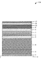
- FIG. 1 is a model structural diagram which shows a spin-valve type magnetoresistance sensor constituting an embodiment of the present invention in model form.
- FIG. 2 is a graph which shows the relationship between the film thickness of the electron-reflective layer and the sheet resistance in one embodiment of a sensor.
- FIG. 3 is a graph which shows the relationship of the film thickness of the electron-reflective layer in a case where the back layer is constructed from copper to the amount of change in the magnetic resistance and the rate of change of the magnetic resistance.
- FIG. 4 is a graph which shows the relationship of the film thickness of the electron-reflective layer in a case where the back layer is constructed from a two layer film of copper and ruthenium to the amount of change in the magnetic resistance and the rate of change of the magnetic resistance.
- FIG. 5 shows sectional electron micrographs that illustrate the oxidized state in cases where the film thickness of the electron-reflective layer was respectively set at 1.0 nm and 3.0 nm.
- FIG. 6 is a graph which shows the MR—magnetic field curve of a spin-valve type magnetoresistance sensor constituting one embodiment of the present invention.
- FIG. 7 is a graph showing experimental results obtained for the Cu back layer film thickness dependence of the spin-valve type magnetoresistance sensor of the present invention.
- FIG. 8 is another graph showing similar experimental results obtained for the Cu back layer film thickness dependence.
- a method and apparatus for a magnetoresistance sensor are described. For purposes of discussing and illustrating the invention, several examples will be given in the context of a thin-film magnetic head. However, one skilled in the art will recognize and appreciate that the sensor may be used for sensing magnetic flux for other uses, for example, to sense voids in structures by inducing eddy currents in a material.
- the spin-valve type magnetoresistance sensor of the present invention is equipped with a free ferromagnetic layer, a pinned ferromagnetic layer, a non-magnetic spacer layer which is sandwiched between the aforementioned ferromagnetic layers, an anti-ferromagnetic layer which is disposed adjacent to the aforementioned pinned ferromagnetic layer and which is used to pin the direction of magnetization of said pinned ferromagnetic layer, a non-magnetic back layer which is disposed adjacent to the aforementioned free ferromagnetic layer and which is stacked on the opposite side the free ferromagnetic layer from the aforementioned nonmagnetic spacer layer, and an electron-reflective layer which is disposed adjacent to the aforementioned back layer and which is stacked on the opposite side of the back layer from the aforementioned free ferromagnetic layer.
- Such a spin-valve type magnetoresistance sensor may be part of a thin-film magnetic head, and may be used in a magnetic recording device,
- the spin-valve type magnetoresistance sensor of the present invention is equipped with a back layer, the mean free path of the conductive electrons is extended, so that the conductance of the sensor and the magnetic resistance effect ratio (MR ratio) are increased. Furthermore, as a result of the electron-reflective layer, at least some of the conductive electrons that move from the free ferromagnetic layer to the opposite side [of the free ferromagnetic layer] from the spacer layer are mirror-reflected by the interface between the electron-reflective layer and the back layer, and some of these reflected electrons contribute to an increase in the magnetic resistance effect based on the spin-valve effect, so that a further increase in the MR ratio is achieved.
- MR ratio magnetic resistance effect ratio
- the electron-reflective layer is constructed from an oxide insulating layer that has a high electron reflection efficiency
- the back layer functions as an anti-oxidation layer, and since the oxide insulating layer that reflects the conductive electrons and the free ferromagnetic layer are not in direct contact with each other, a deterioration in the soft magnetic characteristics caused by the oxidation of the free ferromagnetic layer can be avoided.
- this structure is also a so-called spin-filter structure which is equipped with a non-magnetic conductive back layer, the following advantage is also simultaneously obtained: specifically, the bias current center moves from the non-magnetic spacer layer toward the free layer, so that the bias current magnetic field in the free layer is reduced, thus reducing the asymmetry of the output.
- the abovementioned electron-reflective layer may consist of a metal oxide which is formed by forming a film of a metal that is more easily oxidized than the constituent material of the back layer on the surface of the back layer, and oxidizing this intermediate-product metal layer in an oxidizing atmosphere. In this way, an elastic mirror reflection of conductive electrons by an electron-reflective layer consisting of a metal oxide is obtained.
- the electron-reflective layer is obtained by first forming an intermediate-product metal layer which is a non-oxide, and then naturally oxidizing this intermediate-product metal layer, an electron-reflective layer consisting of a metal oxide can be formed while preventing the oxidation of the free ferromagnetic layer and back layer in the manufacturing process. Furthermore, by using a metal that is more easily oxidized than the constituent material of the back layer (e.g., copper, etc.) as the constituent metal of the electron-reflective layer, it is possible to suppress a drop in conductance caused by the oxidation of the back layer over time.
- the relative ease of oxidation of an element generally corresponds to the ionization tendency of the element. Accordingly, it is desirable to form the abovementioned intermediate-product metal layer from a metal that shows a greater tendency toward ionization than the constituent metal of the abovementioned back layer, and to subject this intermediate-product metal layer to natural oxidation.
- the film thickness of the abovementioned intermediate-product metal layer be set at 0.50 to 1.75 nm. If this thickness is less than 0.50 nm, the layer may not function adequately as an electron-reflective layer; furthermore, control of the film thickness is difficult, and the output characteristics following the subsequent oxidation process may be unstable, thus causing a drop in the yield. On the other hand, if this thickness exceeds 1.75 nm, it may be difficult to cause complete oxidation of the constituent metal, and in cases where the metal is not completely oxidized, the sectional structure of the electron-reflective layer becomes a two-layer structure consisting of a metal oxide layer and a metal layer.
- the electron-reflective layer is intrinsically formed from a highly insulating material and installed in order to reflect electrons; however, in the case of a two-layer structure of the type described above, the portion that is adjacent to the back layer becomes a metal layer, so that the electrical resistance drops compared to that of an oxide layer, thus resulting in a certain degree of current flow. Specifically, conductive electrons may enter the metal layer that constitutes the interface with the back layer, so that the layer cannot function completely as an electron-reflective layer.
- the abovementioned back layer may be formed from a metal that has the property of acting as an oxidizing agent with respect to the electron-reflective layer.
- a typical example of such a metal is copper (Cu); if the back layer is formed from copper, the effect in extending the mean free path of the conductive electrons is large, so that the conductance and MR ratio can be increased.
- the film thickness of the non-magnetic back layer is less than 0.5 nm, the layer does not function sufficiently as a back layer, so that no great change is seen in the MR ratio. On the other hand, if this thickness exceeds 1.5 nm, the shunt loss of the conductive electrons is large, so that the MR ratio may conversely drop. Accordingly, in this embodiment, it is desirable that this thickness be in the range of 0.5 to 1.5 nm.
- the mean free path of the conductive electrons can be increased by the back layer. Furthermore, the conductive electrons are reflected by the electron-reflective layer so that an effective contribution to the spin-valve effect can be made, thus making it possible to obtain a large MR ratio while achieving a further increase in the sensitivity of the sensor.
- the film thickness of the free ferromagnetic layer can be made smaller than the mean free path of the conductive electrons in the ferromagnetic layer, so that the magnetic recording density of the magnetic recording device may be further increased.
- an embodiment of the present invention in a the thin-film magnetic head using the abovementioned spin-valve type magnetoresistance sensor as a playback magnetic flux sensing element may be preferably realized as a shielded magnetic resistance effect type head.
- the present invention may be used in a spin-valve MR sensor of any configuration that has a free ferromagnetic layer, a non-magnetic conductive spacer layer, a pinned ferromagnetic layer and an anti-ferromagnetic layer.
- the present invention may be used in both so-called bottom spin-valve films, and top spin-valve films in which the anti-ferromagnetic layer is located on the opposite side of the substrate with both ferromagnetic layers interposed.
- the spin-valve MR sensor of the present invention may also be used in the magnetic heads of magnetic recording devices such as hard disks, etc., and can be used as a magnetism-sensing element in various other types of devices.
- a ferromagnetic alloy such as NiFe or CoFe, etc.
- NiFe or CoFe may be used as the free ferromagnetic layer.
- a two-layer film of NiFe/CoFe may be used, with the CoFe stacked on the non-magnetic spacer layer.
- This embodiment may be preferable, because: in the case of a spin-valve film which uses Cu in the non-magnetic spacer layer and NiFe in the ferromagnetic layers, the Ni in the NiFe becomes mixed with the Cu when the film is heated to a temperature of 200° C. or greater as a result of heat treatment during the manufacturing process or the generation of heat during operation, etc., such that the multilayer structure may be disturbed.
- CoFe has a relatively large coercive force, so that it is difficult for the magnetization of the free ferromagnetic layer to rotate. Accordingly, by stacking NiFe (which has a small coercive force) with CoFe as described above, and increasing the film thickness of the NiFe film to some extent, it is possible to facilitate the rotation of the direction of magnetization of the CoFe film, which has a large coercive force.
- An IB transition metal such as Cu, Ag or Au, etc., may be used as the nonmagnetic spacer layer. Such metals are superior in terms of conductivity, and exhibit a sufficient function as a spacer layer.
- anti-ferromagnetic layer Various materials such as Mn type anti-ferromagnetic materials, Cr type anti-ferromagnetic materials or oxide type anti-ferromagnetic materials, etc., may be used for the anti-ferromagnetic layer.
- PtMn, PdMn and NiMn which are Mn type anti-ferromagnetic materials, are anti-ferromagnetic regular alloys that have a CuAu—I type crystal structure. These alloys are known to show a large exchange-coupling magnetic field at an Mn content of 50%. Furthermore, IrMn, RhMn and FeMn are anti-ferromagnetic irregular alloys that have a fcc (face-centered cubic) structure, and are known to impart unidirectional anisotropy to the pinned layer without heat treatment. Moreover, CrMn is an anti-ferromagnetic alloy that has a bcc (body-centered cubic) structure. In addition, PdPtMn alloys and CrPtMn alloys, etc., are also known to show a large exchange-coupling magnetic field, a high blocking temperature and good corrosion resistance.
- CrAl is an example of a Cr type anti-ferromagnetic material.
- CrAl is an anti-ferromagnetic irregular alloy, which has a bcc structure. This alloy shows a high Neel temperature, a high electrical resistivity and high corrosion resistance; furthermore, unidirectional anisotropy is generated without heat treatment.
- Oxides such as ⁇ -Fe203, NiO and CoO, etc. are examples of oxide type anti-ferromagnetic materials, as is a two-layer film of NiO/CoO. These oxides are superior in terms of corrosion resistance, and since these oxides are insulators, they have a high resistivity, so that there is little shunt loss of the sensing current. Accordingly, such oxides may be advantageous for achieving a high output.
- the non-magnetic back layer may be formed from a non-magnetic conductive material such as Cu, etc.; this layer may also be formed by multi-layer films. Such a two-layer film, is that of Cu/Ru.
- the electron-reflective layer be formed from a tantalum oxide layer because this tantalum oxide can be manufactured from metallic tantalum by natural oxidation.
- the tantalum oxide is an insulator and accordingly, this oxide is suitable as an electron-reflective layer.
- the film thickness of the metallic tantalum layer that is formed during the manufacture of the aforementioned tantalum oxide layer is 0.5 nm to 1.75 nm, the oxidation residue of the metallic tantalum layer is small and the electron reflectivity is high, so the MR ratio is increased.
- Various other materials besides the abovementioned tantalum oxide may be used as the aforementioned electron-reflective layer.
- Metal oxides such as zirconium oxide, titanium oxide, hafnium oxide, silicon oxide, aluminum oxide, germanium oxide and zinc oxide, etc., which can be manufactured by natural oxidation, and semiconductors with a large band gap such as diamond, silicon carbide and zinc sulfide, etc., have a large potential barrier at the metal interface, and are advantageous for increasing the electron reflectivity.
- the present invention may be realized as a thin-film magnetic head which is equipped with the abovementioned spin-valve type magnetoresistance sensor as a playback magnetic flux sensing element. Since the soft magnetic characteristics of the free ferromagnetic layer of the spin-valve film in such a thin-film magnetic head are desirable, the head characteristics are stabilized, and a high playback output may be obtained at the same time.
- a thin-film magnetic head is advantageous for use in a magnetic recording device such as a hard disk, etc.
- a layer may be formed by a film or other method and that a structure may be a series of layers and/or films.
- a structure may be a series of layers and/or films.
- the use of the words “film” and/or “layer” may be considered synonymous as representing a material thickness, consistent with the standard definition of a film as a thin layer.
- FIG. 1 The construction of a spin-valve MR sensor applying the present invention as is illustrated in FIG. 1 may be as follows:
- an underlayer with a two-layer structure constructed from a first underlayer film 2 consisting of Ta and a second underlayer film 3 consisting of NiFcCr is formed on the surface of a substrate 1 consisting of glass, silicon, or ceramic material, such as, Al-103/TiC, etc., in order to increase the crystal orientation of the overall film formed above.
- An MR film is formed on top of this underlayer by stacking various types of constituent layers.
- This MR film is a film known as a synthetic spin-valve film in which a pinned layer with a three-layer structure constructed from a ferromagnetic film 5 consisting of a Co alloy, a non-magnetic film 6 consisting of Ru and a ferromagnetic film 7 consisting of a Co alloy is formed on the surface of an anti-ferromagnetic layer film 4 consisting of a PtMn film, which is in turn formed on the surface of the aforementioned underlayers 2 and 3 . Both of the aforementioned ferromagnetic films 5 and 7 are magnetically integrated by strong anti-parallel coupling.
- a non-magnetic conductive spacer layer 8 consisting of a Cu film is formed on the surface of the aforementioned pinned layer; furthermore, a free layer with a two-structure consisting of a Co alloy film 9 and an NiFe film 10 is stacked on the surface of the aforementioned spacer layer 8 .
- the aforementioned free layer is formed with a smaller thickness than in a conventional spin-valve film in order to obtain a high magnetic field sensitivity.
- An electron-reflective layer 12 is stacked on the surface of the free layer with a back layer 11 consisting of Cu or a two-layer structure of Cu/Ru interposed. As a result of an electron-reflective layer 12 thus being stacked on the uppermost surface, the conductive electrons are reflected by the interface with this electron-reflective layer 12 .
- the mean free path of the conductive electrons is defined as the sum of the rectilinear distances traveled by the electrons before and after mirror reflection, then the mean free path of the conductive electrons is increased as a result of the presence of the electron-reflective layer 12 in the spin-valve film of the present embodiment, so that the MR ratio is increased. Accordingly, a high playback output may be obtained.
- the electron-reflective layer 12 Furthermore, in cases where an oxide such as a tantalum oxide layer, etc., is used as the electron-reflective layer 12 , deterioration of the soft magnetic characteristics of the free layer may be avoided, since this electron-reflective layer 12 does not directly contact the free layer. Accordingly, the head characteristics are more stable.
- an oxide such as a tantalum oxide layer, etc.
- the abovementioned tantalum oxide is formed by stacking a metallic tantalum film, and then oxidizing this metallic tantalum film in an oxidizing atmosphere (e.g., exposing the film to the atmosphere).
- the tantalum is stacked with the metallic tantalum layer controlled to an appropriate film thickness so that there is no oxidation residue; as a result, substantially all of the metallic tantalum is converted into a tantalum oxide layer.
- the aforementioned MR film is subjected to a specified heat treatment in a vacuum magnetic field following film formation, so that the anti-ferromagnetic layer 4 is regularized, thus imparting unidirectional anisotropy to the aforementioned pinned layer by exchange-coupling, so that the magnetic orientation is fixed.
- a similar effect may be obtained by selecting a material having high insulating oxides such as zirconium oxide, titanium oxide, hafnium oxide, silicon oxide, aluminum oxide and germanium oxide, etc., and semiconductors with a large band gap such as zinc oxide, diamond, silicon carbide, and zinc sulfide, etc., as the material of the electron-reflective layer 12 instead of tantalum oxide.
- a material having high insulating oxides such as zirconium oxide, titanium oxide, hafnium oxide, silicon oxide, aluminum oxide and germanium oxide, etc.
- semiconductors with a large band gap such as zinc oxide, diamond, silicon carbide, and zinc sulfide, etc.
- the spin-valve MR film shown in FIG. 1 with a layer construction consisting of Ta (1.5 nm)/NiFeCr (4.0 nm)/PtMn (10.0 nm)/Co alloy (2.0 nm)/Ru (0.85 nm)/Co alloy (2.6 nm)/Cu (2.1 nm)/Co alloy (1.0 nm)/NiFe (2.0 nm)/back layer/electron-reflective layer may be formed on a substrate by DC magnetron sputtering, and following this film formation, a heat treatment for approximately 10 hours at approximately 270° C. in an 11-kilogauss vacuum magnetic field with the film exposed to the atmosphere.
- the back layer may consist of Cu or Cu/Ru
- the electron-reflective layer 12 may consist of tantalum oxide which was formed by natural oxidation following the formation of a metallic tantalum film. Changes in the sheet resistance and MR effect with respect to the film thickness Ta of the tantalum oxide layer were measured for such an embodiment. The results obtained are shown in FIG. 2 through 4 .
- FIG. 2 shows the results obtained for the sheet resistance.
- the sheet resistance rises with a decrease in the film thickness, which agrees with the general tendency.
- the results disagree with this tendency, and show values that are approximately 0.5 to 1.5 ohms lower than expected. This suggests that the mean free path of the conductive electrons is extended by the electron-reflective layer, so that the sheet resistance of the spin-valve film shows a drop.
- FIGS. 3 and 4 show the MR ratio (DR/R) and change in resistance (DR) for respective back layers of Cu and Cu/Ru.
- FIG. 5 shows sectional transmission electron micrographs of the abovementioned spin-valve films. It is seen that in a film in which the metallic tantalum layer was formed with a film thickness of 3.0 nm, a two-layer structure consisting of a metallic tantalum layer and a tantalum oxide layer was formed following natural oxidation, while in a film in which the metallic tantalum layer was formed with a film thickness of 1.0 nm, all of the metallic tantalum layer was converted into tantalum oxide following natural oxidation.
- FIG. 6 shows the MR—magnetic field curve of the spin-valve film of the present invention in this embodiment.
- the coercive force read from this curve is extremely small, i.e., approximately 1.2 Oersted, thus indicating that the soft magnetic characteristics of the free layer are good.
- these samples were subjected to a heat treatment for 10 hours at 270° C., and the MR ratios and amounts of change in conductance ( ⁇ G) of these samples were determined by experiment. Furthermore, the sheet resistance of the spin-valve films was measured by the four-terminal resistance measurement method, and it was confirmed by the fluorescent X-ray measurement method (XRF) that the film thicknesses of the respective layers were accurate film thicknesses.
- XRF fluorescent X-ray measurement method
- the MR ratio (DR/R) is increased compared to the ratio obtained when there is no back layer, both in the case of a 1.25 nm Ta film and in the case of a 3.0 nm Ta film. Furthermore, the largest MR ratio was obtained when the Cu back layer had a thickness of 1 nm.
- the MR ratio obtained is larger than that obtained in the case of a Ta film thickness of 3.0 nm, and the rate of increase in the MR ratio is also larger. It is seen from this that when the thickness of the Ta film is 1.25 nm, all of the tantalum is oxidized so that the film functions reliably as an electron-reflective layer, thus contributing greatly to the increase in the MR ratio.
- the thickness of the Cu back layer is approximately 2.0 nm or greater, no great difference in characteristics is seen between a Ta film thickness of 1.25 mu and a Ta film thickness of 3.0 nm.
- the apparent reason for this is that when the thickness of the Cu back layer is large, the contribution of the film thickness is greater than the contribution of electron reflection.
- the spin-valve type magnetoresistance sensor of the present invention can manifest a large MR effect as a result of the action of an electron-reflective layer, so that a high playback output can be obtained.
- the electron-reflective layer being stacked with a back layer interposed, favorable soft magnetic characteristics of the free layer can be maintained, so that the operation of the head can be stabilized, and a high recording density may be realized in magnetic recording by utilizing the present invention as a playback thin-film magnetic head in a magnetic recording device.
Abstract
Description
Claims (7)
Applications Claiming Priority (2)
| Application Number | Priority Date | Filing Date | Title |
|---|---|---|---|
| JP2000109442A JP2001308411A (en) | 2000-04-11 | 2000-04-11 | Spin bubble type magnetoresistance sensor and thin film magnetic head |
| JP2000-109442 | 2000-04-11 |
Publications (2)
| Publication Number | Publication Date |
|---|---|
| US20020004147A1 US20020004147A1 (en) | 2002-01-10 |
| US7026063B2 true US7026063B2 (en) | 2006-04-11 |
Family
ID=18622135
Family Applications (1)
| Application Number | Title | Priority Date | Filing Date |
|---|---|---|---|
| US09/816,601 Expired - Lifetime US7026063B2 (en) | 2000-04-11 | 2001-03-23 | Spin-valve type magnetoresistance sensor and thin-film magnetic head |
Country Status (2)
| Country | Link |
|---|---|
| US (1) | US7026063B2 (en) |
| JP (1) | JP2001308411A (en) |
Cited By (132)
| Publication number | Priority date | Publication date | Assignee | Title |
|---|---|---|---|---|
| US7417832B1 (en) | 2005-04-26 | 2008-08-26 | Western Digital (Fremont), Llc | Magnetoresistive structure having a novel specular and filter layer combination |
| US7684160B1 (en) | 2006-02-06 | 2010-03-23 | Western Digital (Fremont), Llc | Magnetoresistive structure having a novel specular and barrier layer combination |
| US8830628B1 (en) | 2009-02-23 | 2014-09-09 | Western Digital (Fremont), Llc | Method and system for providing a perpendicular magnetic recording head |
| US8879207B1 (en) | 2011-12-20 | 2014-11-04 | Western Digital (Fremont), Llc | Method for providing a side shield for a magnetic recording transducer using an air bridge |
| US8883017B1 (en) | 2013-03-12 | 2014-11-11 | Western Digital (Fremont), Llc | Method and system for providing a read transducer having seamless interfaces |
| US8917581B1 (en) | 2013-12-18 | 2014-12-23 | Western Digital Technologies, Inc. | Self-anneal process for a near field transducer and chimney in a hard disk drive assembly |
| US8923102B1 (en) | 2013-07-16 | 2014-12-30 | Western Digital (Fremont), Llc | Optical grating coupling for interferometric waveguides in heat assisted magnetic recording heads |
| US8947985B1 (en) | 2013-07-16 | 2015-02-03 | Western Digital (Fremont), Llc | Heat assisted magnetic recording transducers having a recessed pole |
| US8953422B1 (en) | 2014-06-10 | 2015-02-10 | Western Digital (Fremont), Llc | Near field transducer using dielectric waveguide core with fine ridge feature |
| US8958272B1 (en) | 2014-06-10 | 2015-02-17 | Western Digital (Fremont), Llc | Interfering near field transducer for energy assisted magnetic recording |
| US8971160B1 (en) | 2013-12-19 | 2015-03-03 | Western Digital (Fremont), Llc | Near field transducer with high refractive index pin for heat assisted magnetic recording |
| US8970988B1 (en) | 2013-12-31 | 2015-03-03 | Western Digital (Fremont), Llc | Electric gaps and method for making electric gaps for multiple sensor arrays |
| US8976635B1 (en) | 2014-06-10 | 2015-03-10 | Western Digital (Fremont), Llc | Near field transducer driven by a transverse electric waveguide for energy assisted magnetic recording |
| US8982508B1 (en) | 2011-10-31 | 2015-03-17 | Western Digital (Fremont), Llc | Method for providing a side shield for a magnetic recording transducer |
| US8980109B1 (en) | 2012-12-11 | 2015-03-17 | Western Digital (Fremont), Llc | Method for providing a magnetic recording transducer using a combined main pole and side shield CMP for a wraparound shield scheme |
| US8984740B1 (en) | 2012-11-30 | 2015-03-24 | Western Digital (Fremont), Llc | Process for providing a magnetic recording transducer having a smooth magnetic seed layer |
| US8988825B1 (en) | 2014-02-28 | 2015-03-24 | Western Digital (Fremont, LLC | Method for fabricating a magnetic writer having half-side shields |
| US8988812B1 (en) | 2013-11-27 | 2015-03-24 | Western Digital (Fremont), Llc | Multi-sensor array configuration for a two-dimensional magnetic recording (TDMR) operation |
| US8993217B1 (en) | 2013-04-04 | 2015-03-31 | Western Digital (Fremont), Llc | Double exposure technique for high resolution disk imaging |
| US8995087B1 (en) | 2006-11-29 | 2015-03-31 | Western Digital (Fremont), Llc | Perpendicular magnetic recording write head having a wrap around shield |
| US9001628B1 (en) | 2013-12-16 | 2015-04-07 | Western Digital (Fremont), Llc | Assistant waveguides for evaluating main waveguide coupling efficiency and diode laser alignment tolerances for hard disk |
| US9001467B1 (en) | 2014-03-05 | 2015-04-07 | Western Digital (Fremont), Llc | Method for fabricating side shields in a magnetic writer |
| US8997832B1 (en) | 2010-11-23 | 2015-04-07 | Western Digital (Fremont), Llc | Method of fabricating micrometer scale components |
| US9007879B1 (en) | 2014-06-10 | 2015-04-14 | Western Digital (Fremont), Llc | Interfering near field transducer having a wide metal bar feature for energy assisted magnetic recording |
| US9007725B1 (en) | 2014-10-07 | 2015-04-14 | Western Digital (Fremont), Llc | Sensor with positive coupling between dual ferromagnetic free layer laminates |
| US9007719B1 (en) | 2013-10-23 | 2015-04-14 | Western Digital (Fremont), Llc | Systems and methods for using double mask techniques to achieve very small features |
| US9013836B1 (en) | 2013-04-02 | 2015-04-21 | Western Digital (Fremont), Llc | Method and system for providing an antiferromagnetically coupled return pole |
| US9042057B1 (en) | 2013-01-09 | 2015-05-26 | Western Digital (Fremont), Llc | Methods for providing magnetic storage elements with high magneto-resistance using Heusler alloys |
| US9042052B1 (en) | 2014-06-23 | 2015-05-26 | Western Digital (Fremont), Llc | Magnetic writer having a partially shunted coil |
| US9042208B1 (en) | 2013-03-11 | 2015-05-26 | Western Digital Technologies, Inc. | Disk drive measuring fly height by applying a bias voltage to an electrically insulated write component of a head |
| US9042051B2 (en) | 2013-08-15 | 2015-05-26 | Western Digital (Fremont), Llc | Gradient write gap for perpendicular magnetic recording writer |
| US9042058B1 (en) | 2013-10-17 | 2015-05-26 | Western Digital Technologies, Inc. | Shield designed for middle shields in a multiple sensor array |
| US9053735B1 (en) | 2014-06-20 | 2015-06-09 | Western Digital (Fremont), Llc | Method for fabricating a magnetic writer using a full-film metal planarization |
| US9064528B1 (en) | 2013-05-17 | 2015-06-23 | Western Digital Technologies, Inc. | Interferometric waveguide usable in shingled heat assisted magnetic recording in the absence of a near-field transducer |
| US9064527B1 (en) | 2013-04-12 | 2015-06-23 | Western Digital (Fremont), Llc | High order tapered waveguide for use in a heat assisted magnetic recording head |
| US9065043B1 (en) | 2012-06-29 | 2015-06-23 | Western Digital (Fremont), Llc | Tunnel magnetoresistance read head with narrow shield-to-shield spacing |
| US9064507B1 (en) | 2009-07-31 | 2015-06-23 | Western Digital (Fremont), Llc | Magnetic etch-stop layer for magnetoresistive read heads |
| US9070381B1 (en) | 2013-04-12 | 2015-06-30 | Western Digital (Fremont), Llc | Magnetic recording read transducer having a laminated free layer |
| US9082423B1 (en) | 2013-12-18 | 2015-07-14 | Western Digital (Fremont), Llc | Magnetic recording write transducer having an improved trailing surface profile |
| US9087534B1 (en) | 2011-12-20 | 2015-07-21 | Western Digital (Fremont), Llc | Method and system for providing a read transducer having soft and hard magnetic bias structures |
| US9087527B1 (en) | 2014-10-28 | 2015-07-21 | Western Digital (Fremont), Llc | Apparatus and method for middle shield connection in magnetic recording transducers |
| US9093639B2 (en) | 2012-02-21 | 2015-07-28 | Western Digital (Fremont), Llc | Methods for manufacturing a magnetoresistive structure utilizing heating and cooling |
| US9104107B1 (en) | 2013-04-03 | 2015-08-11 | Western Digital (Fremont), Llc | DUV photoresist process |
| US9111550B1 (en) | 2014-12-04 | 2015-08-18 | Western Digital (Fremont), Llc | Write transducer having a magnetic buffer layer spaced between a side shield and a write pole by non-magnetic layers |
| US9111564B1 (en) | 2013-04-02 | 2015-08-18 | Western Digital (Fremont), Llc | Magnetic recording writer having a main pole with multiple flare angles |
| US9111558B1 (en) | 2014-03-14 | 2015-08-18 | Western Digital (Fremont), Llc | System and method of diffractive focusing of light in a waveguide |
| US9123358B1 (en) | 2012-06-11 | 2015-09-01 | Western Digital (Fremont), Llc | Conformal high moment side shield seed layer for perpendicular magnetic recording writer |
| US9123362B1 (en) | 2011-03-22 | 2015-09-01 | Western Digital (Fremont), Llc | Methods for assembling an electrically assisted magnetic recording (EAMR) head |
| US9123374B1 (en) | 2015-02-12 | 2015-09-01 | Western Digital (Fremont), Llc | Heat assisted magnetic recording writer having an integrated polarization rotation plate |
| US9123359B1 (en) | 2010-12-22 | 2015-09-01 | Western Digital (Fremont), Llc | Magnetic recording transducer with sputtered antiferromagnetic coupling trilayer between plated ferromagnetic shields and method of fabrication |
| US9135937B1 (en) | 2014-05-09 | 2015-09-15 | Western Digital (Fremont), Llc | Current modulation on laser diode for energy assisted magnetic recording transducer |
| US9135930B1 (en) | 2014-03-06 | 2015-09-15 | Western Digital (Fremont), Llc | Method for fabricating a magnetic write pole using vacuum deposition |
| US9142233B1 (en) | 2014-02-28 | 2015-09-22 | Western Digital (Fremont), Llc | Heat assisted magnetic recording writer having a recessed pole |
| US9147404B1 (en) | 2015-03-31 | 2015-09-29 | Western Digital (Fremont), Llc | Method and system for providing a read transducer having a dual free layer |
| US9147408B1 (en) | 2013-12-19 | 2015-09-29 | Western Digital (Fremont), Llc | Heated AFM layer deposition and cooling process for TMR magnetic recording sensor with high pinning field |
| US9153255B1 (en) | 2014-03-05 | 2015-10-06 | Western Digital (Fremont), Llc | Method for fabricating a magnetic writer having an asymmetric gap and shields |
| US9183854B2 (en) | 2014-02-24 | 2015-11-10 | Western Digital (Fremont), Llc | Method to make interferometric taper waveguide for HAMR light delivery |
| US9190079B1 (en) | 2014-09-22 | 2015-11-17 | Western Digital (Fremont), Llc | Magnetic write pole having engineered radius of curvature and chisel angle profiles |
| US9190085B1 (en) | 2014-03-12 | 2015-11-17 | Western Digital (Fremont), Llc | Waveguide with reflective grating for localized energy intensity |
| US9194692B1 (en) | 2013-12-06 | 2015-11-24 | Western Digital (Fremont), Llc | Systems and methods for using white light interferometry to measure undercut of a bi-layer structure |
| US9202480B2 (en) | 2009-10-14 | 2015-12-01 | Western Digital (Fremont), LLC. | Double patterning hard mask for damascene perpendicular magnetic recording (PMR) writer |
| US9202493B1 (en) | 2014-02-28 | 2015-12-01 | Western Digital (Fremont), Llc | Method of making an ultra-sharp tip mode converter for a HAMR head |
| US9214165B1 (en) | 2014-12-18 | 2015-12-15 | Western Digital (Fremont), Llc | Magnetic writer having a gradient in saturation magnetization of the shields |
| US9214172B2 (en) | 2013-10-23 | 2015-12-15 | Western Digital (Fremont), Llc | Method of manufacturing a magnetic read head |
| US9214169B1 (en) | 2014-06-20 | 2015-12-15 | Western Digital (Fremont), Llc | Magnetic recording read transducer having a laminated free layer |
| US9213322B1 (en) | 2012-08-16 | 2015-12-15 | Western Digital (Fremont), Llc | Methods for providing run to run process control using a dynamic tuner |
| US9230565B1 (en) | 2014-06-24 | 2016-01-05 | Western Digital (Fremont), Llc | Magnetic shield for magnetic recording head |
| US9236560B1 (en) | 2014-12-08 | 2016-01-12 | Western Digital (Fremont), Llc | Spin transfer torque tunneling magnetoresistive device having a laminated free layer with perpendicular magnetic anisotropy |
| US9245545B1 (en) | 2013-04-12 | 2016-01-26 | Wester Digital (Fremont), Llc | Short yoke length coils for magnetic heads in disk drives |
| US9245543B1 (en) | 2010-06-25 | 2016-01-26 | Western Digital (Fremont), Llc | Method for providing an energy assisted magnetic recording head having a laser integrally mounted to the slider |
| US9245562B1 (en) | 2015-03-30 | 2016-01-26 | Western Digital (Fremont), Llc | Magnetic recording writer with a composite main pole |
| US9251813B1 (en) | 2009-04-19 | 2016-02-02 | Western Digital (Fremont), Llc | Method of making a magnetic recording head |
| US9263071B1 (en) | 2015-03-31 | 2016-02-16 | Western Digital (Fremont), Llc | Flat NFT for heat assisted magnetic recording |
| US9263067B1 (en) | 2013-05-29 | 2016-02-16 | Western Digital (Fremont), Llc | Process for making PMR writer with constant side wall angle |
| US9269382B1 (en) | 2012-06-29 | 2016-02-23 | Western Digital (Fremont), Llc | Method and system for providing a read transducer having improved pinning of the pinned layer at higher recording densities |
| US9275657B1 (en) | 2013-08-14 | 2016-03-01 | Western Digital (Fremont), Llc | Process for making PMR writer with non-conformal side gaps |
| US9280990B1 (en) | 2013-12-11 | 2016-03-08 | Western Digital (Fremont), Llc | Method for fabricating a magnetic writer using multiple etches |
| US9287494B1 (en) | 2013-06-28 | 2016-03-15 | Western Digital (Fremont), Llc | Magnetic tunnel junction (MTJ) with a magnesium oxide tunnel barrier |
| US9286919B1 (en) | 2014-12-17 | 2016-03-15 | Western Digital (Fremont), Llc | Magnetic writer having a dual side gap |
| US9305583B1 (en) | 2014-02-18 | 2016-04-05 | Western Digital (Fremont), Llc | Method for fabricating a magnetic writer using multiple etches of damascene materials |
| US9312064B1 (en) | 2015-03-02 | 2016-04-12 | Western Digital (Fremont), Llc | Method to fabricate a magnetic head including ion milling of read gap using dual layer hard mask |
| US9318130B1 (en) | 2013-07-02 | 2016-04-19 | Western Digital (Fremont), Llc | Method to fabricate tunneling magnetic recording heads with extended pinned layer |
| US9336814B1 (en) | 2013-03-12 | 2016-05-10 | Western Digital (Fremont), Llc | Inverse tapered waveguide for use in a heat assisted magnetic recording head |
| US9343086B1 (en) | 2013-09-11 | 2016-05-17 | Western Digital (Fremont), Llc | Magnetic recording write transducer having an improved sidewall angle profile |
| US9343098B1 (en) | 2013-08-23 | 2016-05-17 | Western Digital (Fremont), Llc | Method for providing a heat assisted magnetic recording transducer having protective pads |
| US9343087B1 (en) | 2014-12-21 | 2016-05-17 | Western Digital (Fremont), Llc | Method for fabricating a magnetic writer having half shields |
| US9349394B1 (en) | 2013-10-18 | 2016-05-24 | Western Digital (Fremont), Llc | Method for fabricating a magnetic writer having a gradient side gap |
| US9349392B1 (en) | 2012-05-24 | 2016-05-24 | Western Digital (Fremont), Llc | Methods for improving adhesion on dielectric substrates |
| US9361913B1 (en) | 2013-06-03 | 2016-06-07 | Western Digital (Fremont), Llc | Recording read heads with a multi-layer AFM layer methods and apparatuses |
| US9361914B1 (en) | 2014-06-18 | 2016-06-07 | Western Digital (Fremont), Llc | Magnetic sensor with thin capping layer |
| US9368134B1 (en) | 2010-12-16 | 2016-06-14 | Western Digital (Fremont), Llc | Method and system for providing an antiferromagnetically coupled writer |
| US9384765B1 (en) | 2015-09-24 | 2016-07-05 | Western Digital (Fremont), Llc | Method and system for providing a HAMR writer having improved optical efficiency |
| US9384763B1 (en) | 2015-03-26 | 2016-07-05 | Western Digital (Fremont), Llc | Dual free layer magnetic reader having a rear bias structure including a soft bias layer |
| US9396743B1 (en) | 2014-02-28 | 2016-07-19 | Western Digital (Fremont), Llc | Systems and methods for controlling soft bias thickness for tunnel magnetoresistance readers |
| US9396742B1 (en) | 2012-11-30 | 2016-07-19 | Western Digital (Fremont), Llc | Magnetoresistive sensor for a magnetic storage system read head, and fabrication method thereof |
| US9406331B1 (en) | 2013-06-17 | 2016-08-02 | Western Digital (Fremont), Llc | Method for making ultra-narrow read sensor and read transducer device resulting therefrom |
| US9424866B1 (en) | 2015-09-24 | 2016-08-23 | Western Digital (Fremont), Llc | Heat assisted magnetic recording write apparatus having a dielectric gap |
| US9431031B1 (en) | 2015-03-24 | 2016-08-30 | Western Digital (Fremont), Llc | System and method for magnetic transducers having multiple sensors and AFC shields |
| US9431038B1 (en) | 2015-06-29 | 2016-08-30 | Western Digital (Fremont), Llc | Method for fabricating a magnetic write pole having an improved sidewall angle profile |
| US9431032B1 (en) | 2013-08-14 | 2016-08-30 | Western Digital (Fremont), Llc | Electrical connection arrangement for a multiple sensor array usable in two-dimensional magnetic recording |
| US9431039B1 (en) | 2013-05-21 | 2016-08-30 | Western Digital (Fremont), Llc | Multiple sensor array usable in two-dimensional magnetic recording |
| US9431047B1 (en) | 2013-05-01 | 2016-08-30 | Western Digital (Fremont), Llc | Method for providing an improved AFM reader shield |
| US9437251B1 (en) | 2014-12-22 | 2016-09-06 | Western Digital (Fremont), Llc | Apparatus and method having TDMR reader to reader shunts |
| US9443541B1 (en) | 2015-03-24 | 2016-09-13 | Western Digital (Fremont), Llc | Magnetic writer having a gradient in saturation magnetization of the shields and return pole |
| US9441938B1 (en) | 2013-10-08 | 2016-09-13 | Western Digital (Fremont), Llc | Test structures for measuring near field transducer disc length |
| US9449621B1 (en) | 2015-03-26 | 2016-09-20 | Western Digital (Fremont), Llc | Dual free layer magnetic reader having a rear bias structure having a high aspect ratio |
| US9449625B1 (en) | 2014-12-24 | 2016-09-20 | Western Digital (Fremont), Llc | Heat assisted magnetic recording head having a plurality of diffusion barrier layers |
| US9472216B1 (en) | 2015-09-23 | 2016-10-18 | Western Digital (Fremont), Llc | Differential dual free layer magnetic reader |
| US9484051B1 (en) | 2015-11-09 | 2016-11-01 | The Provost, Fellows, Foundation Scholars and the other members of Board, of the College of the Holy and Undivided Trinity of Queen Elizabeth near Dublin | Method and system for reducing undesirable reflections in a HAMR write apparatus |
| US9508372B1 (en) | 2015-06-03 | 2016-11-29 | Western Digital (Fremont), Llc | Shingle magnetic writer having a low sidewall angle pole |
| US9508365B1 (en) | 2015-06-24 | 2016-11-29 | Western Digital (Fremont), LLC. | Magnetic reader having a crystal decoupling structure |
| US9508363B1 (en) | 2014-06-17 | 2016-11-29 | Western Digital (Fremont), Llc | Method for fabricating a magnetic write pole having a leading edge bevel |
| US9530443B1 (en) | 2015-06-25 | 2016-12-27 | Western Digital (Fremont), Llc | Method for fabricating a magnetic recording device having a high aspect ratio structure |
| US9564150B1 (en) | 2015-11-24 | 2017-02-07 | Western Digital (Fremont), Llc | Magnetic read apparatus having an improved read sensor isolation circuit |
| US9595273B1 (en) | 2015-09-30 | 2017-03-14 | Western Digital (Fremont), Llc | Shingle magnetic writer having nonconformal shields |
| US9646639B2 (en) | 2015-06-26 | 2017-05-09 | Western Digital (Fremont), Llc | Heat assisted magnetic recording writer having integrated polarization rotation waveguides |
| US9666214B1 (en) | 2015-09-23 | 2017-05-30 | Western Digital (Fremont), Llc | Free layer magnetic reader that may have a reduced shield-to-shield spacing |
| US9721595B1 (en) | 2014-12-04 | 2017-08-01 | Western Digital (Fremont), Llc | Method for providing a storage device |
| US9741366B1 (en) | 2014-12-18 | 2017-08-22 | Western Digital (Fremont), Llc | Method for fabricating a magnetic writer having a gradient in saturation magnetization of the shields |
| US9740805B1 (en) | 2015-12-01 | 2017-08-22 | Western Digital (Fremont), Llc | Method and system for detecting hotspots for photolithographically-defined devices |
| US9754611B1 (en) | 2015-11-30 | 2017-09-05 | Western Digital (Fremont), Llc | Magnetic recording write apparatus having a stepped conformal trailing shield |
| US9767831B1 (en) | 2015-12-01 | 2017-09-19 | Western Digital (Fremont), Llc | Magnetic writer having convex trailing surface pole and conformal write gap |
| US9786301B1 (en) | 2014-12-02 | 2017-10-10 | Western Digital (Fremont), Llc | Apparatuses and methods for providing thin shields in a multiple sensor array |
| US9799351B1 (en) | 2015-11-30 | 2017-10-24 | Western Digital (Fremont), Llc | Short yoke length writer having assist coils |
| US9812155B1 (en) | 2015-11-23 | 2017-11-07 | Western Digital (Fremont), Llc | Method and system for fabricating high junction angle read sensors |
| US9842615B1 (en) | 2015-06-26 | 2017-12-12 | Western Digital (Fremont), Llc | Magnetic reader having a nonmagnetic insertion layer for the pinning layer |
| US9858951B1 (en) | 2015-12-01 | 2018-01-02 | Western Digital (Fremont), Llc | Method for providing a multilayer AFM layer in a read sensor |
| US9881638B1 (en) | 2014-12-17 | 2018-01-30 | Western Digital (Fremont), Llc | Method for providing a near-field transducer (NFT) for a heat assisted magnetic recording (HAMR) device |
| US9934811B1 (en) | 2014-03-07 | 2018-04-03 | Western Digital (Fremont), Llc | Methods for controlling stray fields of magnetic features using magneto-elastic anisotropy |
| US9953670B1 (en) | 2015-11-10 | 2018-04-24 | Western Digital (Fremont), Llc | Method and system for providing a HAMR writer including a multi-mode interference device |
| US10037770B1 (en) | 2015-11-12 | 2018-07-31 | Western Digital (Fremont), Llc | Method for providing a magnetic recording write apparatus having a seamless pole |
| US10074387B1 (en) | 2014-12-21 | 2018-09-11 | Western Digital (Fremont), Llc | Method and system for providing a read transducer having symmetric antiferromagnetically coupled shields |
Families Citing this family (4)
| Publication number | Priority date | Publication date | Assignee | Title |
|---|---|---|---|---|
| JP3623417B2 (en) * | 1999-12-03 | 2005-02-23 | アルプス電気株式会社 | Spin valve thin film magnetic element and thin film magnetic head |
| JP4024499B2 (en) * | 2001-08-15 | 2007-12-19 | 株式会社東芝 | Magnetoresistive element, magnetic head, and magnetic reproducing apparatus |
| US6913782B2 (en) * | 2002-12-03 | 2005-07-05 | Hitachi Global Storage Technologies Netherlands B.V. | Fabrication of self-aligned reflective/protective overlays on magnetoresistance sensors, and the sensors |
| JP4864464B2 (en) * | 2006-01-11 | 2012-02-01 | 株式会社東芝 | Magnetoresistive element, manufacturing method thereof, magnetic head, magnetic reproducing apparatus and magnetic memory using the same |
Citations (11)
| Publication number | Priority date | Publication date | Assignee | Title |
|---|---|---|---|---|
| WO1994011889A1 (en) | 1992-11-16 | 1994-05-26 | Nonvolatile Electronics, Inc. | Magnetoresistive structure with alloy layer |
| EP0611033A2 (en) | 1993-02-08 | 1994-08-17 | International Business Machines Corporation | A magnetoresistive spin valve sensor and magnetic storage system incorporating such a sensor |
| US6181534B1 (en) * | 1998-11-09 | 2001-01-30 | International Business Machines Corporation | Antiparallel (AP) pinned spin valve sensor with specular reflection of conduction electrons |
| US6201673B1 (en) | 1999-04-02 | 2001-03-13 | Read-Rite Corporation | System for biasing a synthetic free layer in a magnetoresistance sensor |
| US6219208B1 (en) * | 1999-06-25 | 2001-04-17 | International Business Machines Corporation | Dual spin valve sensor with self-pinned layer specular reflector |
| US6271997B1 (en) | 1999-11-22 | 2001-08-07 | International Business Machines Corporation | Read head spin valve sensor with triple antiparallel coupled free layer structure |
| US6313973B1 (en) | 1998-06-30 | 2001-11-06 | Kabushiki Kaisha Toshiba | Laminated magnetorestrictive element of an exchange coupling film, an antiferromagnetic film and a ferromagnetic film and a magnetic disk drive using same |
| US20010046110A1 (en) * | 1996-11-28 | 2001-11-29 | Yasuhiro Kawawake | Magnetoresistive device having a highly smooth metal reflective layer |
| US6338899B1 (en) * | 1998-06-30 | 2002-01-15 | Kabushiki Kaisha Toshiba | Magnetoresistance effect element, magnetic head, magnetic head assembly, magnetic storage system |
| US6348274B1 (en) * | 1998-12-28 | 2002-02-19 | Kabushiki Kaisha Toshiba | Magnetoresistive element and magnetic recording apparatus |
| US6567246B1 (en) * | 1999-03-02 | 2003-05-20 | Matsushita Electric Industrial Co., Ltd. | Magnetoresistance effect element and method for producing the same, and magnetoresistance effect type head, magnetic recording apparatus, and magnetoresistance effect memory element |
-
2000
- 2000-04-11 JP JP2000109442A patent/JP2001308411A/en not_active Withdrawn
-
2001
- 2001-03-23 US US09/816,601 patent/US7026063B2/en not_active Expired - Lifetime
Patent Citations (12)
| Publication number | Priority date | Publication date | Assignee | Title |
|---|---|---|---|---|
| WO1994011889A1 (en) | 1992-11-16 | 1994-05-26 | Nonvolatile Electronics, Inc. | Magnetoresistive structure with alloy layer |
| EP0611033A2 (en) | 1993-02-08 | 1994-08-17 | International Business Machines Corporation | A magnetoresistive spin valve sensor and magnetic storage system incorporating such a sensor |
| US5422571A (en) | 1993-02-08 | 1995-06-06 | International Business Machines Corporation | Magnetoresistive spin valve sensor having a nonmagnetic back layer |
| US20010046110A1 (en) * | 1996-11-28 | 2001-11-29 | Yasuhiro Kawawake | Magnetoresistive device having a highly smooth metal reflective layer |
| US6313973B1 (en) | 1998-06-30 | 2001-11-06 | Kabushiki Kaisha Toshiba | Laminated magnetorestrictive element of an exchange coupling film, an antiferromagnetic film and a ferromagnetic film and a magnetic disk drive using same |
| US6338899B1 (en) * | 1998-06-30 | 2002-01-15 | Kabushiki Kaisha Toshiba | Magnetoresistance effect element, magnetic head, magnetic head assembly, magnetic storage system |
| US6181534B1 (en) * | 1998-11-09 | 2001-01-30 | International Business Machines Corporation | Antiparallel (AP) pinned spin valve sensor with specular reflection of conduction electrons |
| US6348274B1 (en) * | 1998-12-28 | 2002-02-19 | Kabushiki Kaisha Toshiba | Magnetoresistive element and magnetic recording apparatus |
| US6567246B1 (en) * | 1999-03-02 | 2003-05-20 | Matsushita Electric Industrial Co., Ltd. | Magnetoresistance effect element and method for producing the same, and magnetoresistance effect type head, magnetic recording apparatus, and magnetoresistance effect memory element |
| US6201673B1 (en) | 1999-04-02 | 2001-03-13 | Read-Rite Corporation | System for biasing a synthetic free layer in a magnetoresistance sensor |
| US6219208B1 (en) * | 1999-06-25 | 2001-04-17 | International Business Machines Corporation | Dual spin valve sensor with self-pinned layer specular reflector |
| US6271997B1 (en) | 1999-11-22 | 2001-08-07 | International Business Machines Corporation | Read head spin valve sensor with triple antiparallel coupled free layer structure |
Non-Patent Citations (1)
| Title |
|---|
| Kamiguchi, Y., et al., CoFe Specular Spin Valves with a Nano Oxide Layer; Digests of INTERMAG 99; 1999 IEEE International Magnetics Conference Digest of Technical Papers. |
Cited By (152)
| Publication number | Priority date | Publication date | Assignee | Title |
|---|---|---|---|---|
| US7417832B1 (en) | 2005-04-26 | 2008-08-26 | Western Digital (Fremont), Llc | Magnetoresistive structure having a novel specular and filter layer combination |
| US7684160B1 (en) | 2006-02-06 | 2010-03-23 | Western Digital (Fremont), Llc | Magnetoresistive structure having a novel specular and barrier layer combination |
| US8995087B1 (en) | 2006-11-29 | 2015-03-31 | Western Digital (Fremont), Llc | Perpendicular magnetic recording write head having a wrap around shield |
| US8830628B1 (en) | 2009-02-23 | 2014-09-09 | Western Digital (Fremont), Llc | Method and system for providing a perpendicular magnetic recording head |
| US9251813B1 (en) | 2009-04-19 | 2016-02-02 | Western Digital (Fremont), Llc | Method of making a magnetic recording head |
| US9064507B1 (en) | 2009-07-31 | 2015-06-23 | Western Digital (Fremont), Llc | Magnetic etch-stop layer for magnetoresistive read heads |
| US9202480B2 (en) | 2009-10-14 | 2015-12-01 | Western Digital (Fremont), LLC. | Double patterning hard mask for damascene perpendicular magnetic recording (PMR) writer |
| US9245543B1 (en) | 2010-06-25 | 2016-01-26 | Western Digital (Fremont), Llc | Method for providing an energy assisted magnetic recording head having a laser integrally mounted to the slider |
| US9159345B1 (en) | 2010-11-23 | 2015-10-13 | Western Digital (Fremont), Llc | Micrometer scale components |
| US8997832B1 (en) | 2010-11-23 | 2015-04-07 | Western Digital (Fremont), Llc | Method of fabricating micrometer scale components |
| US9672847B2 (en) | 2010-11-23 | 2017-06-06 | Western Digital (Fremont), Llc | Micrometer scale components |
| US9368134B1 (en) | 2010-12-16 | 2016-06-14 | Western Digital (Fremont), Llc | Method and system for providing an antiferromagnetically coupled writer |
| US9123359B1 (en) | 2010-12-22 | 2015-09-01 | Western Digital (Fremont), Llc | Magnetic recording transducer with sputtered antiferromagnetic coupling trilayer between plated ferromagnetic shields and method of fabrication |
| US9123362B1 (en) | 2011-03-22 | 2015-09-01 | Western Digital (Fremont), Llc | Methods for assembling an electrically assisted magnetic recording (EAMR) head |
| US8982508B1 (en) | 2011-10-31 | 2015-03-17 | Western Digital (Fremont), Llc | Method for providing a side shield for a magnetic recording transducer |
| US9087534B1 (en) | 2011-12-20 | 2015-07-21 | Western Digital (Fremont), Llc | Method and system for providing a read transducer having soft and hard magnetic bias structures |
| US8879207B1 (en) | 2011-12-20 | 2014-11-04 | Western Digital (Fremont), Llc | Method for providing a side shield for a magnetic recording transducer using an air bridge |
| US9093639B2 (en) | 2012-02-21 | 2015-07-28 | Western Digital (Fremont), Llc | Methods for manufacturing a magnetoresistive structure utilizing heating and cooling |
| US9349392B1 (en) | 2012-05-24 | 2016-05-24 | Western Digital (Fremont), Llc | Methods for improving adhesion on dielectric substrates |
| US9940950B2 (en) | 2012-05-24 | 2018-04-10 | Western Digital (Fremont), Llc | Methods for improving adhesion on dielectric substrates |
| US9123358B1 (en) | 2012-06-11 | 2015-09-01 | Western Digital (Fremont), Llc | Conformal high moment side shield seed layer for perpendicular magnetic recording writer |
| US9065043B1 (en) | 2012-06-29 | 2015-06-23 | Western Digital (Fremont), Llc | Tunnel magnetoresistance read head with narrow shield-to-shield spacing |
| US9269382B1 (en) | 2012-06-29 | 2016-02-23 | Western Digital (Fremont), Llc | Method and system for providing a read transducer having improved pinning of the pinned layer at higher recording densities |
| US9412400B2 (en) | 2012-06-29 | 2016-08-09 | Western Digital (Fremont), Llc | Tunnel magnetoresistance read head with narrow shield-to-shield spacing |
| US9213322B1 (en) | 2012-08-16 | 2015-12-15 | Western Digital (Fremont), Llc | Methods for providing run to run process control using a dynamic tuner |
| US9396742B1 (en) | 2012-11-30 | 2016-07-19 | Western Digital (Fremont), Llc | Magnetoresistive sensor for a magnetic storage system read head, and fabrication method thereof |
| US8984740B1 (en) | 2012-11-30 | 2015-03-24 | Western Digital (Fremont), Llc | Process for providing a magnetic recording transducer having a smooth magnetic seed layer |
| US8980109B1 (en) | 2012-12-11 | 2015-03-17 | Western Digital (Fremont), Llc | Method for providing a magnetic recording transducer using a combined main pole and side shield CMP for a wraparound shield scheme |
| US9042057B1 (en) | 2013-01-09 | 2015-05-26 | Western Digital (Fremont), Llc | Methods for providing magnetic storage elements with high magneto-resistance using Heusler alloys |
| US9042208B1 (en) | 2013-03-11 | 2015-05-26 | Western Digital Technologies, Inc. | Disk drive measuring fly height by applying a bias voltage to an electrically insulated write component of a head |
| US9336814B1 (en) | 2013-03-12 | 2016-05-10 | Western Digital (Fremont), Llc | Inverse tapered waveguide for use in a heat assisted magnetic recording head |
| US8883017B1 (en) | 2013-03-12 | 2014-11-11 | Western Digital (Fremont), Llc | Method and system for providing a read transducer having seamless interfaces |
| US9013836B1 (en) | 2013-04-02 | 2015-04-21 | Western Digital (Fremont), Llc | Method and system for providing an antiferromagnetically coupled return pole |
| US9111564B1 (en) | 2013-04-02 | 2015-08-18 | Western Digital (Fremont), Llc | Magnetic recording writer having a main pole with multiple flare angles |
| US9104107B1 (en) | 2013-04-03 | 2015-08-11 | Western Digital (Fremont), Llc | DUV photoresist process |
| US8993217B1 (en) | 2013-04-04 | 2015-03-31 | Western Digital (Fremont), Llc | Double exposure technique for high resolution disk imaging |
| US9070381B1 (en) | 2013-04-12 | 2015-06-30 | Western Digital (Fremont), Llc | Magnetic recording read transducer having a laminated free layer |
| US9245545B1 (en) | 2013-04-12 | 2016-01-26 | Wester Digital (Fremont), Llc | Short yoke length coils for magnetic heads in disk drives |
| US9064527B1 (en) | 2013-04-12 | 2015-06-23 | Western Digital (Fremont), Llc | High order tapered waveguide for use in a heat assisted magnetic recording head |
| US9431047B1 (en) | 2013-05-01 | 2016-08-30 | Western Digital (Fremont), Llc | Method for providing an improved AFM reader shield |
| US9064528B1 (en) | 2013-05-17 | 2015-06-23 | Western Digital Technologies, Inc. | Interferometric waveguide usable in shingled heat assisted magnetic recording in the absence of a near-field transducer |
| US9431039B1 (en) | 2013-05-21 | 2016-08-30 | Western Digital (Fremont), Llc | Multiple sensor array usable in two-dimensional magnetic recording |
| US9263067B1 (en) | 2013-05-29 | 2016-02-16 | Western Digital (Fremont), Llc | Process for making PMR writer with constant side wall angle |
| US9361913B1 (en) | 2013-06-03 | 2016-06-07 | Western Digital (Fremont), Llc | Recording read heads with a multi-layer AFM layer methods and apparatuses |
| US9406331B1 (en) | 2013-06-17 | 2016-08-02 | Western Digital (Fremont), Llc | Method for making ultra-narrow read sensor and read transducer device resulting therefrom |
| US9287494B1 (en) | 2013-06-28 | 2016-03-15 | Western Digital (Fremont), Llc | Magnetic tunnel junction (MTJ) with a magnesium oxide tunnel barrier |
| US9318130B1 (en) | 2013-07-02 | 2016-04-19 | Western Digital (Fremont), Llc | Method to fabricate tunneling magnetic recording heads with extended pinned layer |
| US8947985B1 (en) | 2013-07-16 | 2015-02-03 | Western Digital (Fremont), Llc | Heat assisted magnetic recording transducers having a recessed pole |
| US8923102B1 (en) | 2013-07-16 | 2014-12-30 | Western Digital (Fremont), Llc | Optical grating coupling for interferometric waveguides in heat assisted magnetic recording heads |
| US9275657B1 (en) | 2013-08-14 | 2016-03-01 | Western Digital (Fremont), Llc | Process for making PMR writer with non-conformal side gaps |
| US9431032B1 (en) | 2013-08-14 | 2016-08-30 | Western Digital (Fremont), Llc | Electrical connection arrangement for a multiple sensor array usable in two-dimensional magnetic recording |
| US9042051B2 (en) | 2013-08-15 | 2015-05-26 | Western Digital (Fremont), Llc | Gradient write gap for perpendicular magnetic recording writer |
| US9343098B1 (en) | 2013-08-23 | 2016-05-17 | Western Digital (Fremont), Llc | Method for providing a heat assisted magnetic recording transducer having protective pads |
| US9343086B1 (en) | 2013-09-11 | 2016-05-17 | Western Digital (Fremont), Llc | Magnetic recording write transducer having an improved sidewall angle profile |
| US9441938B1 (en) | 2013-10-08 | 2016-09-13 | Western Digital (Fremont), Llc | Test structures for measuring near field transducer disc length |
| US9042058B1 (en) | 2013-10-17 | 2015-05-26 | Western Digital Technologies, Inc. | Shield designed for middle shields in a multiple sensor array |
| US9349394B1 (en) | 2013-10-18 | 2016-05-24 | Western Digital (Fremont), Llc | Method for fabricating a magnetic writer having a gradient side gap |
| US9830936B2 (en) | 2013-10-23 | 2017-11-28 | Western Digital (Fremont), Llc | Magnetic read head with antiferromagentic layer |
| US9007719B1 (en) | 2013-10-23 | 2015-04-14 | Western Digital (Fremont), Llc | Systems and methods for using double mask techniques to achieve very small features |
| US9214172B2 (en) | 2013-10-23 | 2015-12-15 | Western Digital (Fremont), Llc | Method of manufacturing a magnetic read head |
| US8988812B1 (en) | 2013-11-27 | 2015-03-24 | Western Digital (Fremont), Llc | Multi-sensor array configuration for a two-dimensional magnetic recording (TDMR) operation |
| US9194692B1 (en) | 2013-12-06 | 2015-11-24 | Western Digital (Fremont), Llc | Systems and methods for using white light interferometry to measure undercut of a bi-layer structure |
| US9280990B1 (en) | 2013-12-11 | 2016-03-08 | Western Digital (Fremont), Llc | Method for fabricating a magnetic writer using multiple etches |
| US9001628B1 (en) | 2013-12-16 | 2015-04-07 | Western Digital (Fremont), Llc | Assistant waveguides for evaluating main waveguide coupling efficiency and diode laser alignment tolerances for hard disk |
| US8917581B1 (en) | 2013-12-18 | 2014-12-23 | Western Digital Technologies, Inc. | Self-anneal process for a near field transducer and chimney in a hard disk drive assembly |
| US9082423B1 (en) | 2013-12-18 | 2015-07-14 | Western Digital (Fremont), Llc | Magnetic recording write transducer having an improved trailing surface profile |
| US8971160B1 (en) | 2013-12-19 | 2015-03-03 | Western Digital (Fremont), Llc | Near field transducer with high refractive index pin for heat assisted magnetic recording |
| US9147408B1 (en) | 2013-12-19 | 2015-09-29 | Western Digital (Fremont), Llc | Heated AFM layer deposition and cooling process for TMR magnetic recording sensor with high pinning field |
| US8970988B1 (en) | 2013-12-31 | 2015-03-03 | Western Digital (Fremont), Llc | Electric gaps and method for making electric gaps for multiple sensor arrays |
| US9305583B1 (en) | 2014-02-18 | 2016-04-05 | Western Digital (Fremont), Llc | Method for fabricating a magnetic writer using multiple etches of damascene materials |
| US9183854B2 (en) | 2014-02-24 | 2015-11-10 | Western Digital (Fremont), Llc | Method to make interferometric taper waveguide for HAMR light delivery |
| US9396743B1 (en) | 2014-02-28 | 2016-07-19 | Western Digital (Fremont), Llc | Systems and methods for controlling soft bias thickness for tunnel magnetoresistance readers |
| US8988825B1 (en) | 2014-02-28 | 2015-03-24 | Western Digital (Fremont, LLC | Method for fabricating a magnetic writer having half-side shields |
| US9142233B1 (en) | 2014-02-28 | 2015-09-22 | Western Digital (Fremont), Llc | Heat assisted magnetic recording writer having a recessed pole |
| US9202493B1 (en) | 2014-02-28 | 2015-12-01 | Western Digital (Fremont), Llc | Method of making an ultra-sharp tip mode converter for a HAMR head |
| US9153255B1 (en) | 2014-03-05 | 2015-10-06 | Western Digital (Fremont), Llc | Method for fabricating a magnetic writer having an asymmetric gap and shields |
| US9349393B2 (en) | 2014-03-05 | 2016-05-24 | Western Digital (Fremont), Llc | Magnetic writer having an asymmetric gap and shields |
| US9001467B1 (en) | 2014-03-05 | 2015-04-07 | Western Digital (Fremont), Llc | Method for fabricating side shields in a magnetic writer |
| US9135930B1 (en) | 2014-03-06 | 2015-09-15 | Western Digital (Fremont), Llc | Method for fabricating a magnetic write pole using vacuum deposition |
| US9934811B1 (en) | 2014-03-07 | 2018-04-03 | Western Digital (Fremont), Llc | Methods for controlling stray fields of magnetic features using magneto-elastic anisotropy |
| US9190085B1 (en) | 2014-03-12 | 2015-11-17 | Western Digital (Fremont), Llc | Waveguide with reflective grating for localized energy intensity |
| US9495984B2 (en) | 2014-03-12 | 2016-11-15 | Western Digital (Fremont), Llc | Waveguide with reflective grating for localized energy intensity |
| US9111558B1 (en) | 2014-03-14 | 2015-08-18 | Western Digital (Fremont), Llc | System and method of diffractive focusing of light in a waveguide |
| US9135937B1 (en) | 2014-05-09 | 2015-09-15 | Western Digital (Fremont), Llc | Current modulation on laser diode for energy assisted magnetic recording transducer |
| US8958272B1 (en) | 2014-06-10 | 2015-02-17 | Western Digital (Fremont), Llc | Interfering near field transducer for energy assisted magnetic recording |
| US9311952B2 (en) | 2014-06-10 | 2016-04-12 | Western Digital (Fremont), Llc | Interfering near field transducer for energy assisted magnetic recording |
| US9159346B1 (en) | 2014-06-10 | 2015-10-13 | Western Digital (Fremont), Llc | Near field transducer using dielectric waveguide core with fine ridge feature |
| US8976635B1 (en) | 2014-06-10 | 2015-03-10 | Western Digital (Fremont), Llc | Near field transducer driven by a transverse electric waveguide for energy assisted magnetic recording |
| US8953422B1 (en) | 2014-06-10 | 2015-02-10 | Western Digital (Fremont), Llc | Near field transducer using dielectric waveguide core with fine ridge feature |
| US9007879B1 (en) | 2014-06-10 | 2015-04-14 | Western Digital (Fremont), Llc | Interfering near field transducer having a wide metal bar feature for energy assisted magnetic recording |
| US9508363B1 (en) | 2014-06-17 | 2016-11-29 | Western Digital (Fremont), Llc | Method for fabricating a magnetic write pole having a leading edge bevel |
| US9361914B1 (en) | 2014-06-18 | 2016-06-07 | Western Digital (Fremont), Llc | Magnetic sensor with thin capping layer |
| US9053735B1 (en) | 2014-06-20 | 2015-06-09 | Western Digital (Fremont), Llc | Method for fabricating a magnetic writer using a full-film metal planarization |
| US9214169B1 (en) | 2014-06-20 | 2015-12-15 | Western Digital (Fremont), Llc | Magnetic recording read transducer having a laminated free layer |
| US9042052B1 (en) | 2014-06-23 | 2015-05-26 | Western Digital (Fremont), Llc | Magnetic writer having a partially shunted coil |
| US9230565B1 (en) | 2014-06-24 | 2016-01-05 | Western Digital (Fremont), Llc | Magnetic shield for magnetic recording head |
| US9190079B1 (en) | 2014-09-22 | 2015-11-17 | Western Digital (Fremont), Llc | Magnetic write pole having engineered radius of curvature and chisel angle profiles |
| US9007725B1 (en) | 2014-10-07 | 2015-04-14 | Western Digital (Fremont), Llc | Sensor with positive coupling between dual ferromagnetic free layer laminates |
| US9087527B1 (en) | 2014-10-28 | 2015-07-21 | Western Digital (Fremont), Llc | Apparatus and method for middle shield connection in magnetic recording transducers |
| US9786301B1 (en) | 2014-12-02 | 2017-10-10 | Western Digital (Fremont), Llc | Apparatuses and methods for providing thin shields in a multiple sensor array |
| US9111550B1 (en) | 2014-12-04 | 2015-08-18 | Western Digital (Fremont), Llc | Write transducer having a magnetic buffer layer spaced between a side shield and a write pole by non-magnetic layers |
| US10460751B2 (en) | 2014-12-04 | 2019-10-29 | Western Digital (Fremont), Llc | Stripe height lapping control structures for a multiple sensor array |
| US9721595B1 (en) | 2014-12-04 | 2017-08-01 | Western Digital (Fremont), Llc | Method for providing a storage device |
| US10008222B2 (en) | 2014-12-04 | 2018-06-26 | Western Digital (Fremont), Llc | Stripe height lapping control structures for a multiple sensor array |
| US9236560B1 (en) | 2014-12-08 | 2016-01-12 | Western Digital (Fremont), Llc | Spin transfer torque tunneling magnetoresistive device having a laminated free layer with perpendicular magnetic anisotropy |
| US9705072B2 (en) | 2014-12-08 | 2017-07-11 | Western Digital (Fremont), Llc | Spin transfer torque tunneling magnetoresistive device having a laminated free layer with perpendicular magnetic anisotropy |
| US9881638B1 (en) | 2014-12-17 | 2018-01-30 | Western Digital (Fremont), Llc | Method for providing a near-field transducer (NFT) for a heat assisted magnetic recording (HAMR) device |
| US9286919B1 (en) | 2014-12-17 | 2016-03-15 | Western Digital (Fremont), Llc | Magnetic writer having a dual side gap |
| US10553241B2 (en) | 2014-12-17 | 2020-02-04 | Western Digital Technologies, Inc. | Near-field transducer (NFT) for a heat assisted magnetic recording (HAMR) device |
| US9741366B1 (en) | 2014-12-18 | 2017-08-22 | Western Digital (Fremont), Llc | Method for fabricating a magnetic writer having a gradient in saturation magnetization of the shields |
| US9214165B1 (en) | 2014-12-18 | 2015-12-15 | Western Digital (Fremont), Llc | Magnetic writer having a gradient in saturation magnetization of the shields |
| US10074387B1 (en) | 2014-12-21 | 2018-09-11 | Western Digital (Fremont), Llc | Method and system for providing a read transducer having symmetric antiferromagnetically coupled shields |
| US9343087B1 (en) | 2014-12-21 | 2016-05-17 | Western Digital (Fremont), Llc | Method for fabricating a magnetic writer having half shields |
| US9437251B1 (en) | 2014-12-22 | 2016-09-06 | Western Digital (Fremont), Llc | Apparatus and method having TDMR reader to reader shunts |
| US9449625B1 (en) | 2014-12-24 | 2016-09-20 | Western Digital (Fremont), Llc | Heat assisted magnetic recording head having a plurality of diffusion barrier layers |
| US9123374B1 (en) | 2015-02-12 | 2015-09-01 | Western Digital (Fremont), Llc | Heat assisted magnetic recording writer having an integrated polarization rotation plate |
| US9312064B1 (en) | 2015-03-02 | 2016-04-12 | Western Digital (Fremont), Llc | Method to fabricate a magnetic head including ion milling of read gap using dual layer hard mask |
| US9443541B1 (en) | 2015-03-24 | 2016-09-13 | Western Digital (Fremont), Llc | Magnetic writer having a gradient in saturation magnetization of the shields and return pole |
| US9431031B1 (en) | 2015-03-24 | 2016-08-30 | Western Digital (Fremont), Llc | System and method for magnetic transducers having multiple sensors and AFC shields |
| US9384763B1 (en) | 2015-03-26 | 2016-07-05 | Western Digital (Fremont), Llc | Dual free layer magnetic reader having a rear bias structure including a soft bias layer |
| US9922672B1 (en) | 2015-03-26 | 2018-03-20 | Western Digital (Fremont), Llc | Dual free layer magnetic reader having a rear bias structure having a high aspect ratio |
| US9449621B1 (en) | 2015-03-26 | 2016-09-20 | Western Digital (Fremont), Llc | Dual free layer magnetic reader having a rear bias structure having a high aspect ratio |
| US9245562B1 (en) | 2015-03-30 | 2016-01-26 | Western Digital (Fremont), Llc | Magnetic recording writer with a composite main pole |
| US9263071B1 (en) | 2015-03-31 | 2016-02-16 | Western Digital (Fremont), Llc | Flat NFT for heat assisted magnetic recording |
| US9147404B1 (en) | 2015-03-31 | 2015-09-29 | Western Digital (Fremont), Llc | Method and system for providing a read transducer having a dual free layer |
| US9508372B1 (en) | 2015-06-03 | 2016-11-29 | Western Digital (Fremont), Llc | Shingle magnetic writer having a low sidewall angle pole |
| US9508365B1 (en) | 2015-06-24 | 2016-11-29 | Western Digital (Fremont), LLC. | Magnetic reader having a crystal decoupling structure |
| US9530443B1 (en) | 2015-06-25 | 2016-12-27 | Western Digital (Fremont), Llc | Method for fabricating a magnetic recording device having a high aspect ratio structure |
| US9842615B1 (en) | 2015-06-26 | 2017-12-12 | Western Digital (Fremont), Llc | Magnetic reader having a nonmagnetic insertion layer for the pinning layer |
| US9646639B2 (en) | 2015-06-26 | 2017-05-09 | Western Digital (Fremont), Llc | Heat assisted magnetic recording writer having integrated polarization rotation waveguides |
| US10242700B2 (en) | 2015-06-26 | 2019-03-26 | Western Digital (Fremont), Llc | Magnetic reader having a nonmagnetic insertion layer for the pinning layer |
| US10037773B2 (en) | 2015-06-26 | 2018-07-31 | Western Digital (Fremont), Llc | Heat assisted magnetic recording writer having integrated polarization rotation waveguides |
| US9431038B1 (en) | 2015-06-29 | 2016-08-30 | Western Digital (Fremont), Llc | Method for fabricating a magnetic write pole having an improved sidewall angle profile |
| US10121501B2 (en) | 2015-09-23 | 2018-11-06 | Western Digital (Fremont), Llc | Free layer magnetic reader that may have a reduced shield-to-shield spacing |
| US9472216B1 (en) | 2015-09-23 | 2016-10-18 | Western Digital (Fremont), Llc | Differential dual free layer magnetic reader |
| US9666214B1 (en) | 2015-09-23 | 2017-05-30 | Western Digital (Fremont), Llc | Free layer magnetic reader that may have a reduced shield-to-shield spacing |
| US9384765B1 (en) | 2015-09-24 | 2016-07-05 | Western Digital (Fremont), Llc | Method and system for providing a HAMR writer having improved optical efficiency |
| US9424866B1 (en) | 2015-09-24 | 2016-08-23 | Western Digital (Fremont), Llc | Heat assisted magnetic recording write apparatus having a dielectric gap |
| US9595273B1 (en) | 2015-09-30 | 2017-03-14 | Western Digital (Fremont), Llc | Shingle magnetic writer having nonconformal shields |
| US9484051B1 (en) | 2015-11-09 | 2016-11-01 | The Provost, Fellows, Foundation Scholars and the other members of Board, of the College of the Holy and Undivided Trinity of Queen Elizabeth near Dublin | Method and system for reducing undesirable reflections in a HAMR write apparatus |
| US9953670B1 (en) | 2015-11-10 | 2018-04-24 | Western Digital (Fremont), Llc | Method and system for providing a HAMR writer including a multi-mode interference device |
| US10381029B2 (en) | 2015-11-10 | 2019-08-13 | Western Digital (Fremont), Llc | Method and system for providing a HAMR writer including a multi-mode interference device |
| US10037770B1 (en) | 2015-11-12 | 2018-07-31 | Western Digital (Fremont), Llc | Method for providing a magnetic recording write apparatus having a seamless pole |
| US9812155B1 (en) | 2015-11-23 | 2017-11-07 | Western Digital (Fremont), Llc | Method and system for fabricating high junction angle read sensors |
| US9564150B1 (en) | 2015-11-24 | 2017-02-07 | Western Digital (Fremont), Llc | Magnetic read apparatus having an improved read sensor isolation circuit |
| US10121495B2 (en) | 2015-11-30 | 2018-11-06 | Western Digital (Fremont), Llc | Magnetic recording write apparatus having a stepped conformal trailing shield |
| US9799351B1 (en) | 2015-11-30 | 2017-10-24 | Western Digital (Fremont), Llc | Short yoke length writer having assist coils |
| US9754611B1 (en) | 2015-11-30 | 2017-09-05 | Western Digital (Fremont), Llc | Magnetic recording write apparatus having a stepped conformal trailing shield |
| US9858951B1 (en) | 2015-12-01 | 2018-01-02 | Western Digital (Fremont), Llc | Method for providing a multilayer AFM layer in a read sensor |
| US9740805B1 (en) | 2015-12-01 | 2017-08-22 | Western Digital (Fremont), Llc | Method and system for detecting hotspots for photolithographically-defined devices |
| US9767831B1 (en) | 2015-12-01 | 2017-09-19 | Western Digital (Fremont), Llc | Magnetic writer having convex trailing surface pole and conformal write gap |
| US9997177B2 (en) | 2015-12-01 | 2018-06-12 | Western Digital (Fremont), Llc | Magnetic writer having convex trailing surface pole and conformal write gap |
Also Published As
| Publication number | Publication date |
|---|---|
| JP2001308411A (en) | 2001-11-02 |
| US20020004147A1 (en) | 2002-01-10 |
Similar Documents
| Publication | Publication Date | Title |
|---|---|---|
| US7026063B2 (en) | Spin-valve type magnetoresistance sensor and thin-film magnetic head | |
| US7336451B2 (en) | Magnetic sensing element containing half-metallic alloy | |
| JP3976231B2 (en) | Tunnel magnetoresistive element and manufacturing method thereof, and tunnel magnetoresistive head and manufacturing method thereof | |
| US7307818B1 (en) | Method and system for providing a stable spin filter | |
| US6313973B1 (en) | Laminated magnetorestrictive element of an exchange coupling film, an antiferromagnetic film and a ferromagnetic film and a magnetic disk drive using same | |
| JP2778626B2 (en) | Magnetoresistance effect film, method of manufacturing the same, and magnetoresistance effect element | |
| US6295186B1 (en) | Spin-valve magnetoresistive Sensor including a first antiferromagnetic layer for increasing a coercive force and a second antiferromagnetic layer for imposing a longitudinal bias | |
| US6348274B1 (en) | Magnetoresistive element and magnetic recording apparatus | |
| JP3766565B2 (en) | Magnetoresistive film and magnetoresistive head | |
| JP4421822B2 (en) | Bottom spin valve magnetoresistive sensor element and manufacturing method thereof | |
| US6639291B1 (en) | Spin dependent tunneling barriers doped with magnetic particles | |
| US7800867B2 (en) | CPP GMR head with antiferromagnetic layer disposed at rear of ferrimagnetic pinned layer | |
| US7265948B2 (en) | Magnetoresistive element with oxide magnetic layers and metal magnetic films deposited thereon | |
| JPWO2008050790A1 (en) | Tunnel-type magnetic sensing element and manufacturing method thereof | |
| JP4544037B2 (en) | Magnetic sensing element and manufacturing method thereof | |
| US6765769B2 (en) | Magnetoresistive-effect thin film, magnetoresistive-effect element, and magnetoresistive-effect magnetic head | |
| US6982854B2 (en) | Magnetoresistance effect device and magnetoresistance effect head comprising the same, and magnetic recording/reproducing apparatus | |
| JP3181525B2 (en) | Spin valve thin film element and thin film magnetic head using the spin valve thin film element | |
| JP3817399B2 (en) | Magnetoresistive sensor | |
| JP4144831B2 (en) | Magnetoresistive element and magnetic recording apparatus | |
| JP3137598B2 (en) | Magnetoresistive element, magnetic transducer and antiferromagnetic film | |
| US7206173B2 (en) | Magnetoresistive-effect element having a prominent magnetoresistive effect, and method of manufacturing same | |
| JP3859959B2 (en) | Spin valve thin film magnetic element and thin film magnetic head provided with the spin valve thin film magnetic element | |
| US8124253B2 (en) | Tunneling magnetic sensing element including MGO film as insulating barrier layer | |
| JP3872958B2 (en) | Magnetoresistive element and manufacturing method thereof |
Legal Events
| Date | Code | Title | Description |
|---|---|---|---|
| AS | Assignment |
Owner name: READ-RITE CORPORATION, CALIFORNIA Free format text: ASSIGNMENT OF ASSIGNORS INTEREST;ASSIGNORS:UNEO, MASAKI;NISHIDA, HIROSHI;HIKAMI, FUMINORI;REEL/FRAME:012100/0308;SIGNING DATES FROM 20010501 TO 20010606 |
|
| STCF | Information on status: patent grant |
Free format text: PATENTED CASE |
|
| AS | Assignment |
Owner name: WESTERN DIGITAL (FREMONT), LLC, CALIFORNIA Free format text: ASSIGNMENT OF ASSIGNORS INTEREST;ASSIGNOR:READ-RITE CORPORATION;REEL/FRAME:020092/0068 Effective date: 20030731 |
|
| FPAY | Fee payment |
Year of fee payment: 4 |
|
| FPAY | Fee payment |
Year of fee payment: 8 |
|
| AS | Assignment |
Owner name: JPMORGAN CHASE BANK, N.A., AS COLLATERAL AGENT, IL Free format text: SECURITY AGREEMENT;ASSIGNOR:WESTERN DIGITAL (FREMONT), LLC;REEL/FRAME:038710/0845 Effective date: 20160512 Owner name: JPMORGAN CHASE BANK, N.A., AS COLLATERAL AGENT, IL Free format text: SECURITY AGREEMENT;ASSIGNOR:WESTERN DIGITAL (FREMONT), LLC;REEL/FRAME:038744/0755 Effective date: 20160512 Owner name: U.S. BANK NATIONAL ASSOCIATION, AS COLLATERAL AGEN Free format text: SECURITY AGREEMENT;ASSIGNOR:WESTERN DIGITAL (FREMONT), LLC;REEL/FRAME:038744/0675 Effective date: 20160512 |
|
| MAFP | Maintenance fee payment |
Free format text: PAYMENT OF MAINTENANCE FEE, 12TH YEAR, LARGE ENTITY (ORIGINAL EVENT CODE: M1553) Year of fee payment: 12 |
|
| AS | Assignment |
Owner name: WESTERN DIGITAL (FREMONT), LLC, CALIFORNIA Free format text: RELEASE BY SECURED PARTY;ASSIGNOR:U.S. BANK NATIONAL ASSOCIATION, AS COLLATERAL AGENT;REEL/FRAME:045501/0158 Effective date: 20180227 |
|
| AS | Assignment |
Owner name: WESTERN DIGITAL TECHNOLOGIES, INC., CALIFORNIA Free format text: ASSIGNMENT OF ASSIGNORS INTEREST;ASSIGNOR:WESTERN DIGITAL (FREMONT), LLC;REEL/FRAME:050450/0582 Effective date: 20190508 |
|
| AS | Assignment |
Owner name: WESTERN DIGITAL TECHNOLOGIES, INC., CALIFORNIA Free format text: RELEASE OF SECURITY INTEREST AT REEL 038710 FRAME 0845;ASSIGNOR:JPMORGAN CHASE BANK, N.A.;REEL/FRAME:058965/0445 Effective date: 20220203 Owner name: WESTERN DIGITAL (FREMONT), LLC, CALIFORNIA Free format text: RELEASE OF SECURITY INTEREST AT REEL 038710 FRAME 0845;ASSIGNOR:JPMORGAN CHASE BANK, N.A.;REEL/FRAME:058965/0445 Effective date: 20220203 |