US6963816B1 - Systems and methods for integrated emissivity and temperature measurement of a surface - Google Patents
Systems and methods for integrated emissivity and temperature measurement of a surface Download PDFInfo
- Publication number
- US6963816B1 US6963816B1 US10/652,336 US65233603A US6963816B1 US 6963816 B1 US6963816 B1 US 6963816B1 US 65233603 A US65233603 A US 65233603A US 6963816 B1 US6963816 B1 US 6963816B1
- Authority
- US
- United States
- Prior art keywords
- channel
- light
- emissivity
- temperature
- interest
- Prior art date
- Legal status (The legal status is an assumption and is not a legal conclusion. Google has not performed a legal analysis and makes no representation as to the accuracy of the status listed.)
- Expired - Fee Related, expires
Links
- 238000000034 method Methods 0.000 title claims abstract description 26
- 238000009529 body temperature measurement Methods 0.000 title description 3
- 238000002310 reflectometry Methods 0.000 claims abstract description 10
- 238000005259 measurement Methods 0.000 abstract description 13
- 238000001228 spectrum Methods 0.000 abstract description 9
- 230000008569 process Effects 0.000 description 15
- 230000006870 function Effects 0.000 description 7
- 230000005855 radiation Effects 0.000 description 7
- 239000000463 material Substances 0.000 description 5
- 230000003287 optical effect Effects 0.000 description 5
- 239000013307 optical fiber Substances 0.000 description 5
- 238000012545 processing Methods 0.000 description 5
- FBOUIAKEJMZPQG-AWNIVKPZSA-N (1E)-1-(2,4-dichlorophenyl)-4,4-dimethyl-2-(1,2,4-triazol-1-yl)pent-1-en-3-ol Chemical compound C1=NC=NN1/C(C(O)C(C)(C)C)=C/C1=CC=C(Cl)C=C1Cl FBOUIAKEJMZPQG-AWNIVKPZSA-N 0.000 description 3
- 230000005540 biological transmission Effects 0.000 description 3
- 230000035939 shock Effects 0.000 description 3
- PQXKHYXIUOZZFA-UHFFFAOYSA-M lithium fluoride Chemical compound [Li+].[F-] PQXKHYXIUOZZFA-UHFFFAOYSA-M 0.000 description 2
- 238000012986 modification Methods 0.000 description 2
- 230000004048 modification Effects 0.000 description 2
- 229910052594 sapphire Inorganic materials 0.000 description 2
- 239000010980 sapphire Substances 0.000 description 2
- 229910052724 xenon Inorganic materials 0.000 description 2
- FHNFHKCVQCLJFQ-UHFFFAOYSA-N xenon atom Chemical compound [Xe] FHNFHKCVQCLJFQ-UHFFFAOYSA-N 0.000 description 2
- RYGMFSIKBFXOCR-UHFFFAOYSA-N Copper Chemical compound [Cu] RYGMFSIKBFXOCR-UHFFFAOYSA-N 0.000 description 1
- ZOKXTWBITQBERF-UHFFFAOYSA-N Molybdenum Chemical compound [Mo] ZOKXTWBITQBERF-UHFFFAOYSA-N 0.000 description 1
- 238000004616 Pyrometry Methods 0.000 description 1
- 238000003491 array Methods 0.000 description 1
- 229910052802 copper Inorganic materials 0.000 description 1
- 239000010949 copper Substances 0.000 description 1
- 230000008878 coupling Effects 0.000 description 1
- 238000010168 coupling process Methods 0.000 description 1
- 238000005859 coupling reaction Methods 0.000 description 1
- 239000013078 crystal Substances 0.000 description 1
- 230000001419 dependent effect Effects 0.000 description 1
- 238000002474 experimental method Methods 0.000 description 1
- 239000002360 explosive Substances 0.000 description 1
- 239000000835 fiber Substances 0.000 description 1
- 230000004907 flux Effects 0.000 description 1
- -1 for example Substances 0.000 description 1
- 230000007246 mechanism Effects 0.000 description 1
- 239000011859 microparticle Substances 0.000 description 1
- 229910052750 molybdenum Inorganic materials 0.000 description 1
- 239000011733 molybdenum Substances 0.000 description 1
- 239000004071 soot Substances 0.000 description 1
- 230000002123 temporal effect Effects 0.000 description 1
Images


Classifications
-
- G—PHYSICS
- G01—MEASURING; TESTING
- G01K—MEASURING TEMPERATURE; MEASURING QUANTITY OF HEAT; THERMALLY-SENSITIVE ELEMENTS NOT OTHERWISE PROVIDED FOR
- G01K11/00—Measuring temperature based upon physical or chemical changes not covered by groups G01K3/00, G01K5/00, G01K7/00 or G01K9/00
- G01K11/12—Measuring temperature based upon physical or chemical changes not covered by groups G01K3/00, G01K5/00, G01K7/00 or G01K9/00 using changes in colour, translucency or reflectance
- G01K11/125—Measuring temperature based upon physical or chemical changes not covered by groups G01K3/00, G01K5/00, G01K7/00 or G01K9/00 using changes in colour, translucency or reflectance using changes in reflectance
Definitions
- the present invention relates generally to pyrometry and, more particularly, to systems and methods for implementing pyrometric measurements of simple or complex surfaces of interest.
- the spectrum itself does not yield information about the temperature without knowledge or information about the emissivity of the surface as a function of wavelength and possibly angle.
- the emissivity is often assumed to be constant (i.e., the gray body assumption) or to have a prescribed variation with wavelength.
- the emissivity can vary strongly and without regularity as a function of wavelength.
- a lack of knowledge of the emissivity leads to a large uncertainty in the temperature obtained from the radiation measurement.
- the emitted light is compared to a surface having a known temperature, however, the validity of this comparison hinges on the assumption that the surface being measured and the reference temperature have the same emissivity.
- Systems and methods consistent with the present invention add a measurement of reflected and/or incident light to the information used to determine surface emissivity and temperature. Either knowledge of the spectrum of the incident light, or a measurement of the light reflected from a known surface in addition to a measurement of the emitted and the sum of the emitted and the reflected light from the subject surface, allow the computation of the emissivity as a function of wavelength and the temperature of the surface.
- One feature of the present invention is that it does not use absolute values of the measurement. Instead, it uses relative values between channels. The use of relative values cancels out geometry factors and eliminates the need for absolute calibrations.
- Another feature of the present invention is that it is fast enough to be applied to rapidly moving or changing surfaces, such as surfaces of materials that are deformed or shocked by a high pressure impact or explosive.
- a further feature of the present invention is that the fiberoptics for the sensors and fiberoptics for the incoming light are located very nearly at the same point in space to automatically correct for the angle of dependence of the emissivity.
- An example of application of the method to a small and uniform spatial area at one point in time may be given by describing an experiment in which a flat plate is shocked. The method can easily be replicated both in space and time to produce a record of temporal and spatial variations in temperature by usings arrays of sensors, such as can be provided by digital video cameras.
- FIG. 1 illustrates an exemplary system for measuring the emissivity and temperature of a surface consistent with the present invention
- FIG. 2 illustrates an exemplary implementation of the system of FIG. 1 that measures the emissivity and temperature of a shocked surface consistent with the present invention
- FIG. 3 illustrates exemplary components of the spectrometer of FIG. 2 consistent with the invention
- FIGS. 4–5 illustrate an exemplary process that utilizes the relative magnitude of the emitted light in each channel and the incident light spectrum measured in the same channels for measuring the emissivity and temperature of a surface;
- FIGS. 6–7 illustrate an exemplary process that utilizes a measurement of reflected power from a surface having a known reflectivity as a basis for determining the emissivity and temperature of a surface of interest
- FIG. 8 illustrates exemplary plots of emissivity versus temperature that may be employed with the exemplary process of FIGS. 4–5 for determining the emissivity and temperature of a surface
- FIG. 9 illustrates exemplary plots of normalized ratios of measured to calculated emitted power as a function of temperature that may be employed with the exemplary process of FIGS. 6–7 for determining the temperature of a surface.
- FIG. 1 illustrates an exemplary surface emissivity and temperature measurement system 100 consistent with the present invention.
- System 100 may measure the temperature and emissivity of any object or surface using emitted and reflected light from a small area of the object or surface.
- System 100 may include a surface 105 , a light transmission medium 110 , a light source 115 and multiple light detectors 120 - 1 through 120 -N.
- Surface 105 may include any type of simple or complex surface such, for example, a room, people, the ground, etc.
- Light transmission medium 110 may include any type of medium for conveying light from light source 115 to surface 105 , and from surface 105 to light detectors 120 - 1 through 120 -N.
- Light transmission medium 110 may include, for example, one or more optical fibers, lenses, etc.
- Light source 115 may include any type of pulsed light source such as, for example, a xenon high pressure lamp with a sapphire window. One skilled in the art will recognize, however, that other pulsed light sources may equivalently be used.
- Each of light detectors 120 - 1 through 120 -N may include a device for measuring the intensity of light over a given wavelength range (i.e., a channel), such as, for example, a spectrometer or a still or video digital camera.
- Light detectors 120 - 1 through 120 -N, and light source 115 may be aimed to cover the same small area of surface 105 . Though not shown in FIG. 1 , an array of light sources 115 and light detectors 120 may be arranged to produce a temperature map of complex surfaces or objects having different temperatures and emissivities over their surfaces.
- Light detectors 120 - 1 through 120 -N may be aimed to cover the same small area of a surface or object and the emitted light from the surface or object may be measured. Light source 115 may then be activated such that light detectors 120 - 1 through 120 -N may measure the sum of the emitted and reflected light from the surface or object. The emissivity and temperature of the small area covered by light detectors 120 - 1 through 120 -N may then be calculated. In some exemplary implementations, light source 115 can be continuously pulsed to give a continuous reading of a temperature of surface 105 . System 100 may, thus, be replicated in time by pulsing light continuously, and in space by using an array of light detectors 120 .
- Light detectors 120 - 1 through 120 -N may be flashed on and off at a frequency related to the desired time resolution of the temperature measurement, so that (after processing the data) a continuous record of the temperature distribution of a surface or object as a function of time may be obtained.
- a bandpass filter may be place in from of each camera so that each camera only measures a portion of the light spectrum.
- System 100 may use at least three cameras, each having a different bandpass filter. All of the cameras may be aimed to cover the same surface or object and the light emitted from the object may be measured.
- Light source 115 may then be activated and the cameras may measure the sum of the emitted light and the reflected light. Using the measured emitted and reflected light, the emissivity and temperature of each small area covered by a pixel in each of the three cameras may be calculated.
- FIG. 2 illustrates a specific application 200 of system 100 , consistent with the present invention, for measuring the emissivity and temperature of a shocked surface.
- System 200 may include a gas gun 205 , a flyer 210 , a target 215 , a window 220 , an enclosure 225 , an optical coupler 230 , optical fibers 235 , a light source 240 and a spectrometer 245 .
- Gas gun 205 may include conventional driving mechanisms for driving flyer 210 to a predetermined velocity (e.g., 3 km/s) to impact target 215 .
- Flyer 210 may include a high density material such as, for example, copper, though other high density materials may be used.
- Target 215 may include, for example, a plate of material that serves as a target for flyer 210 when driven by gas gun 205 .
- Target 215 may include, for example, a plate of polished molybdenum (though other materials may be used) having a thickness of approximately 6 mm.
- Target 215 may be backed by window 220 that may include a sheet of, for example, lithium fluoride crystal.
- Window 220 may serve to increase the pressure at the interface between target 215 and window 220 relative to a completely released condition. Window 220 may further prevent the creation of ejected micro-particles at the surface of target 215 when flyer 210 impacts target 215 .
- Enclosure 225 may completely enclose the impact point of the flyer 210 upon target 215 , including enclosing window 220 .
- Enclosure 225 may include a cavity with a non-reflecting surface, such as, for example, a cavity darkened by soot to minimize reflections.
- Enclosure 225 may include a “light tight” cavity in which the only entry or egress of light into enclosure 225 is through optical coupler 230 .
- Optical coupler 230 may include a conventional coupling device for connecting the fibers from detectors (not shown) in spectrometer 245 and from light source 240 through enclosure 225 .
- Optical fibers 235 may serve as an optically transmissive medium for conveying light to enclosure 225 from light source 240 and from a surface of target 215 to detectors in spectrometer 245 .
- Light source 240 may include a pulsed light source such as, for example, an xenon high pressure lamp with a sapphire window.
- Spectrometer 245 may include multiple channels for detecting and measuring signals with specified optical wavelengths from a surface of target 215 . The optical measurements from spectrometer 245 may be supplied to a processing device (not shown), such as a conventional computer, for subsequent processing.
- target 215 may be shocked by impact of flyer 210 , with the shock reaching the interface between target 215 and window 220 .
- the radiation from the shocked surface of target 215 emits through window 220 and travels through optical fibers 235 to spectrometer 245 .
- pulsed light source 240 may be fired and radiation may be reflected off of the shocked surface of target 215 .
- the sum of the emitted and the reflected radiation may be measured by spectrometer 245 .
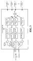
- FIG. 3 illustrates an exemplary spectrometer 245 that may measure radiation emitted or reflected from a target surface consistent with the present invention.
- Spectrometer 245 may include multiple optics 305 - 1 through 305 - m , multiple bandpass filters 310 - 1 through 310 - m , and multiple detectors 315 - 1 through 315 - m .
- Each optics 305 , bandpass filter 310 and detector 315 may be associated with a given channel 320 - 1 through 320 - m (i.e., a given wavelength interval).
- optics 305 - 1 , bandpass filter 310 - 1 and detector 315 - 1 may be associated with channel 1 320 - 1 .
- Each optics 305 may receive signals from optical fiber 235 and may include, for example, a lens.
- Each bandpass filter 310 may receive signals from optics 305 and pass only those signals within its bandpass region to a respective detector 315 .
- Each detector 315 may convert the signals received from a respective bandpass filter 310 to an electrical signal that can be supplied to a processing unit, such as, for example, a personal computer (PC) for subsequent processing.
- a processing unit such as, for example, a personal computer (PC) for subsequent processing.
- FIGS. 4–5 illustrate a first exemplary process for measuring the emissivity and temperature of a surface that utilizes relatives magnitudes of emitted light in each of several channels and the incident light spectrum measured in the same channels.
- knowledge of the geometry of the surface and absolute determination of the emitted and reflected power is not required as long as the light is measured at the same point wherein the incident light originates.
- the exemplary process of FIGS. 4–5 uses the relative magnitude of the emitted light in each of the light detector 120 (or spectrometer 245 ) channels and the incident light spectrum measured in each of the light detector 120 (or spectrometer 245 ) channels to compute the channel emissivites and the surface temperature.
- the exemplary process may begin with the calibration of light detectors 120 - 1 through 120 -N (or spectrometer 145 detectors 215 - 1 through 215 - m ) to determine relative calibration factors C i /C n , where n designates a reference channel to which all other channels are normalized [step 405 ].
- the intensity I i of light emitted by light source 115 or 240 in each channel i may then be measured [act 410 ].
- flyer 210 may then be driven into a surface of target 215 using, for example, gas gun 205 to shock the surface of target 115 .
- An emitted signal S i may be measured in each channel i associated with light detectors 120 - 1 through 120 -N [step 415 ]. After measuring the emitted signal S i in each channel i, light source 115 or 240 may then be pulsed off of surface 105 or the shocked surface of target 215 using the measured power level I i for each channel i of light detectors 120 - 1 through 120 -N [step 420 ].
- a i S i C n /S n C i
- B i F i /F n
- D i R i C n /R n C i
- E i I i /I n .
- An intersection of the all the plots of emissivity ⁇ n versus temperature for each channel i may be located to determine the actual emissivity ⁇ n and the temperature T of surface 105 or target 215 [step 510 ].
- plot 805 represents a plot of ⁇ n vs. T for channel 1 .
- Plot 2 810 represents a plot of ⁇ n vs. T for channel 2 .
- the intersection point 815 represents the solution for the emissivity and temperature of surface 105 or target 215 .
- surface 105 or target 215 has an emissivity ⁇ n of 0.2 at a temperature (T) of 1140 K.
- the emissivities ⁇ i for all the other channels i may then be solved using the determined emissivity ⁇ n for channel n and Eqns. (3)–(9) [step 515 ].
- FIGS. 6–7 illustrate a second exemplary process that utilizes measurements of reflected power from a surface having a known reflectivity as a basis for determining the emissivity and temperature of a given surface.
- a surface having a known reflectivity may be substituted for surface 105 or target 215 and a direct measurement of the reflected signal in each channel i from the substituted surface may be made.
- Surface 105 or target 215 may be substituted back into system 100 or 200 , respectively, and a measurement of the reflected signal in each channel i from surface 105 or target 215 may be made.
- the reflectivity in each channel may be obtained by calculating the ratio of the measured reflected signals.
- the exemplary process of FIGS. 6–7 may begin with the calibration of light detectors 120 - 1 through 120 -N (or spectrometer 145 detectors 215 - 1 through 215 - m ) to determine relative calibration factors C i /C n , where n designates a reference channel to which all other channels are normalized [step 605 ].
- a highly reflective surface, with a precisely know reflectivity r i may be substituted for the surface of interest (e.g., surface 105 or target 215 in systems 100 or 200 , respectively) [step 610 ].
- a reflected signal S Ci may be measured from the highly reflective surface in each channel i by pulsing light source 115 or 240 and measuring the reflected signal S 1 using light detectors 120 - 1 through 120 -N (or spectrometer 145 ) [act 615 ].
- the highly reflective surface may then be replaced with the surface of interest (e.g.,, surface 105 or target 215 ) [step 620 ].
- flyer 210 may then be driven into target 215 , using gas gun 205 , to shock the surface of target 215 .
- the reflected signal S i from the shocked target surface may be measured in each channel i [step 625 ].
- a ratio of measured power to calculated power may be calculated and normalized to a channel n for each channel i [step 710 ] A i e i ⁇ B i ⁇ ( T ) Eqn .
- plot 1 905 represents a plot of the ratio of measured power to calculated power (normalized to channel n) for channel 1 .
- Plot 2 910 represents a plot of the ratio of measured power to calculated power (normalized to channel n) for channel 2 .
- Plot 3 915 represents a plot of the ratio of measured power to calculated power (normalized to channel n) for channel 3 .
- Plot 1 905 , plot 2 910 and plot 3 915 intersect at intersection point 920 at a temperature T 925 of 1140 K.
- Surface 105 or target 115 thus, is 1140 K in the example of FIG. 9 .
Landscapes
- Physics & Mathematics (AREA)
- General Physics & Mathematics (AREA)
- Radiation Pyrometers (AREA)
Abstract
Description
S i=εi F i(T)KC i Eqn. (1)
-
- where
- Si is the surface emission signal in channel i;
- εi is the emissivity of the surface or target in the wavelength interval of channel i;
- Fi is the known black body power in channel i as a function of temperature T;
- K is a geometry factor which is assumed to be independent of the wavelength channel; and
- Ci is a sensor calibration factor for channel i.
The relation for the light reflected fromsurface 105 ortarget 215 is the following:
R i=(1−εi)I i HC i Eqn. (2)
- where
- Ri is the signal corresponding to the reflected light from
light source 115 orlight source 240 in channel i; - Ii is the power of the light from
light source 115 orlight source 240 in channel i; and - H is a geometry factor that may be assumed to be independent of the wavelength of the channel.
In Eqn. (2) above, it has been assumed that the reflectivity is one minus the emissivity for each channel. There are conditions relating to the angular independence of the emissivity that must be satisfied for this relation to be applicable.
- Ri is the signal corresponding to the reflected light from
- where
A i =e i B i(T) Eqn. (3)
D i =E i(1−e iεn)/(1−εn) Eqn. (4)
where e iεi/εn; Eqn. (5)
A i =S i C n /S n C i Eqn. (6)
B i =F i /F n Eqn. (7)
D i =R i C n /R n C i; and Eqn. (8)
E i =I i /I n Eqn. (9)
The values of Ai, Di, Ei and the functional dependence of Bi on T are known. Eqns. (3) and (4) may be solved for the emissivity εn as a function of the temperature T:
SUMi =S i +R i Eqn. (11)
The reflected signal Ri for each channel i may be determined [step 430] according to the following:
R i=SUMi −S i Eqn. (12)
A plot of emissivity εn of the reference channel n for each channel i may then be determined [step 505] using the following relation (e.g., Eqn. (10)):
A i =S i C n /S n C i
B i =F i /F n
D i =R i C n /R n C i; and
E i =I i /I n.
An intersection of the all the plots of emissivity εn versus temperature for each channel i may be located to determine the actual emissivity εn and the temperature T of
The emissivity εi for each channel i may be determined [step 705] according to the following:
εi=1−r i Eqn. (14)
A ratio of measured power to calculated power may be calculated and normalized to a channel n for each channel i [step 710]
The intersection of the plots of Ai/ei B i(7) for each channel i may be found to determine the target surface temperature T [step 715]. For example, as shown in
Claims (4)
εi=1−r i
Priority Applications (1)
| Application Number | Priority Date | Filing Date | Title |
|---|---|---|---|
| US10/652,336 US6963816B1 (en) | 2002-09-04 | 2003-09-02 | Systems and methods for integrated emissivity and temperature measurement of a surface |
Applications Claiming Priority (2)
| Application Number | Priority Date | Filing Date | Title |
|---|---|---|---|
| US40941902P | 2002-09-04 | 2002-09-04 | |
| US10/652,336 US6963816B1 (en) | 2002-09-04 | 2003-09-02 | Systems and methods for integrated emissivity and temperature measurement of a surface |
Publications (1)
| Publication Number | Publication Date |
|---|---|
| US6963816B1 true US6963816B1 (en) | 2005-11-08 |
Family
ID=35207085
Family Applications (1)
| Application Number | Title | Priority Date | Filing Date |
|---|---|---|---|
| US10/652,336 Expired - Fee Related US6963816B1 (en) | 2002-09-04 | 2003-09-02 | Systems and methods for integrated emissivity and temperature measurement of a surface |
Country Status (1)
| Country | Link |
|---|---|
| US (1) | US6963816B1 (en) |
Cited By (4)
| Publication number | Priority date | Publication date | Assignee | Title |
|---|---|---|---|---|
| US20070047615A1 (en) * | 2005-09-01 | 2007-03-01 | Siemens Power Generation, Inc. | Method of measuring in situ differential emissivity and temperature |
| US20070118324A1 (en) * | 2005-11-21 | 2007-05-24 | Sandeep Gulati | Explosive device detection based on differential emissivity |
| CN105318985A (en) * | 2015-12-10 | 2016-02-10 | 厦门大学 | Device and method for measuring surface temperature of object through relative strength of reflected light |
| WO2016083373A1 (en) | 2014-11-27 | 2016-06-02 | Aixtron Se | Method for calibrating a pyrometer arrangement of a cvd or pvd reactor |
Citations (9)
| Publication number | Priority date | Publication date | Assignee | Title |
|---|---|---|---|---|
| US4924478A (en) * | 1983-06-16 | 1990-05-08 | Deutsche Forschungs- Und Versuchsanstalt Fur Luft- Und Raumfahrt E.V. | Method of and device for contactless temperature measurement of an object independently of radiation emissivity |
| US5231595A (en) * | 1983-06-06 | 1993-07-27 | Minolta Camera Kabushiki Kaisha | Pyrometer |
| US5255286A (en) * | 1991-05-17 | 1993-10-19 | Texas Instruments Incorporated | Multi-point pyrometry with real-time surface emissivity compensation |
| US6299346B1 (en) * | 1999-03-08 | 2001-10-09 | C. I. Systems Ltd | Active pyrometry with emissivity extrapolation and compensation |
| US6479801B1 (en) * | 1999-10-22 | 2002-11-12 | Tokyo Electron Limited | Temperature measuring method, temperature control method and processing apparatus |
| US20020192847A1 (en) * | 1998-03-19 | 2002-12-19 | Kabushiki Kaisha Toshiba | Temperature measuring method and apparatus, measuring method for the thickness of the formed film, measuring apparatus for the thickness of the formed film thermometer for wafers |
| US20030067956A1 (en) * | 2001-10-10 | 2003-04-10 | Noritake Co., Limited | Temperature measuring method and apparatus |
| US6682216B1 (en) * | 1999-12-16 | 2004-01-27 | The Regents Of The University Of California | Single-fiber multi-color pyrometry |
| US6733173B1 (en) * | 1996-12-19 | 2004-05-11 | Diamond Power International, Inc. | Pyrometer for measuring the temperature of a gas component within a furnace |
-
2003
- 2003-09-02 US US10/652,336 patent/US6963816B1/en not_active Expired - Fee Related
Patent Citations (9)
| Publication number | Priority date | Publication date | Assignee | Title |
|---|---|---|---|---|
| US5231595A (en) * | 1983-06-06 | 1993-07-27 | Minolta Camera Kabushiki Kaisha | Pyrometer |
| US4924478A (en) * | 1983-06-16 | 1990-05-08 | Deutsche Forschungs- Und Versuchsanstalt Fur Luft- Und Raumfahrt E.V. | Method of and device for contactless temperature measurement of an object independently of radiation emissivity |
| US5255286A (en) * | 1991-05-17 | 1993-10-19 | Texas Instruments Incorporated | Multi-point pyrometry with real-time surface emissivity compensation |
| US6733173B1 (en) * | 1996-12-19 | 2004-05-11 | Diamond Power International, Inc. | Pyrometer for measuring the temperature of a gas component within a furnace |
| US20020192847A1 (en) * | 1998-03-19 | 2002-12-19 | Kabushiki Kaisha Toshiba | Temperature measuring method and apparatus, measuring method for the thickness of the formed film, measuring apparatus for the thickness of the formed film thermometer for wafers |
| US6299346B1 (en) * | 1999-03-08 | 2001-10-09 | C. I. Systems Ltd | Active pyrometry with emissivity extrapolation and compensation |
| US6479801B1 (en) * | 1999-10-22 | 2002-11-12 | Tokyo Electron Limited | Temperature measuring method, temperature control method and processing apparatus |
| US6682216B1 (en) * | 1999-12-16 | 2004-01-27 | The Regents Of The University Of California | Single-fiber multi-color pyrometry |
| US20030067956A1 (en) * | 2001-10-10 | 2003-04-10 | Noritake Co., Limited | Temperature measuring method and apparatus |
Cited By (11)
| Publication number | Priority date | Publication date | Assignee | Title |
|---|---|---|---|---|
| US20070047615A1 (en) * | 2005-09-01 | 2007-03-01 | Siemens Power Generation, Inc. | Method of measuring in situ differential emissivity and temperature |
| US7632012B2 (en) * | 2005-09-01 | 2009-12-15 | Siemens Energy, Inc. | Method of measuring in situ differential emissivity and temperature |
| US20100014555A1 (en) * | 2005-09-01 | 2010-01-21 | Michael Twerdochlib | Method of measuring in situ differential emissivity and temperature |
| US8192077B2 (en) | 2005-09-01 | 2012-06-05 | Siemens Energy, Inc. | Method of measuring in situ differential emissivity and temperature |
| US20070118324A1 (en) * | 2005-11-21 | 2007-05-24 | Sandeep Gulati | Explosive device detection based on differential emissivity |
| US7239974B2 (en) * | 2005-11-21 | 2007-07-03 | Viaspace Security Inc. | Explosive device detection based on differential emissivity |
| WO2016083373A1 (en) | 2014-11-27 | 2016-06-02 | Aixtron Se | Method for calibrating a pyrometer arrangement of a cvd or pvd reactor |
| DE102014117388A1 (en) | 2014-11-27 | 2016-06-02 | Aixtron Se | Method for calibrating a pyrometer arrangement of a CVD or PVD reactor |
| DE102014117388B4 (en) | 2014-11-27 | 2025-03-27 | Aixtron Se | Method for calibrating a pyrometer arrangement of a CVD or PVD reactor |
| CN105318985A (en) * | 2015-12-10 | 2016-02-10 | 厦门大学 | Device and method for measuring surface temperature of object through relative strength of reflected light |
| CN105318985B (en) * | 2015-12-10 | 2018-04-24 | 厦门大学 | A kind of device and method by reflected light relative intensity measure body surface temperature |
Similar Documents
| Publication | Publication Date | Title |
|---|---|---|
| US7495774B2 (en) | Optical air data system | |
| CA1174075A (en) | Laser radiometer | |
| Reichardt et al. | RAMSES: German Meteorological Service autonomous Raman lidar for water vapor, temperature,<? A3B2 show [pmg: line-break justify=" yes"/]?> aerosol, and cloud measurements | |
| US3822098A (en) | Multispectral sensor means measuring depolarized radiation | |
| US4607963A (en) | Multi-channel infrared thermometer | |
| CN114088351B (en) | Multispectral automatic calibration system | |
| US7034939B2 (en) | Calibration system and method for calibration of various types of polarimeters | |
| US6963816B1 (en) | Systems and methods for integrated emissivity and temperature measurement of a surface | |
| EP0660107B1 (en) | Integrated detector for laser remote sensors | |
| US3765779A (en) | Calibration technique and apparatus | |
| Kirkwood et al. | Imaging backscattered and near to backscattered light in ignition scale plasmas | |
| Grams et al. | Compact laser radar for remote atmospheric probing | |
| USH1066H (en) | Airborne infrared transmissometer | |
| JP2615904B2 (en) | Electro-optical equipment | |
| CN108387311A (en) | A kind of laser power meter for realizing adjustable gear using reflected light | |
| CN120334934B (en) | A spaceborne infrared and laser integrated active and passive detection system | |
| Poulsen et al. | Temperature and wavelength dependent emissivity of a shocked surface: A first experiment | |
| Yamada et al. | Thermal imaging system applying two‐color thermometry | |
| Park et al. | Measurement of Asian dust by using multiwavelength lidar | |
| Duncan et al. | Experimental and theoretical assessment of mechanical and optical effects in nonuniformly heated IR windows | |
| Harris et al. | Upgrade in optical measurement capabilities of AEDC ballistic ranges | |
| Deshpande | A brief report on the Infrared Telescope at Gurushikhar, MT Abu | |
| IL110549A (en) | Multipoint temperature monitoring apparatus for semiconductor wafers during processing | |
| James et al. | Electro-optical test collimators for real world systems | |
| CN114593822A (en) | An infrared radiation measurement method and device capable of deducting stray radiation |
Legal Events
| Date | Code | Title | Description |
|---|---|---|---|
| AS | Assignment |
Owner name: ENERGY UNITED STATES DEPARTMENT OF, DISTRICT OF CO Free format text: ASSIGNMENT OF ASSIGNORS INTEREST;ASSIGNOR:POULSEN, PETER;REEL/FRAME:014421/0829 Effective date: 20030903 |
|
| FPAY | Fee payment |
Year of fee payment: 4 |
|
| FPAY | Fee payment |
Year of fee payment: 8 |
|
| REMI | Maintenance fee reminder mailed | ||
| LAPS | Lapse for failure to pay maintenance fees |
Free format text: PATENT EXPIRED FOR FAILURE TO PAY MAINTENANCE FEES (ORIGINAL EVENT CODE: EXP.) |
|
| STCH | Information on status: patent discontinuation |
Free format text: PATENT EXPIRED DUE TO NONPAYMENT OF MAINTENANCE FEES UNDER 37 CFR 1.362 |
|
| FP | Expired due to failure to pay maintenance fee |
Effective date: 20171108 |