US6919829B2 - Bit swapping for different interleaving depths - Google Patents
Bit swapping for different interleaving depths Download PDFInfo
- Publication number
- US6919829B2 US6919829B2 US10/601,338 US60133803A US6919829B2 US 6919829 B2 US6919829 B2 US 6919829B2 US 60133803 A US60133803 A US 60133803A US 6919829 B2 US6919829 B2 US 6919829B2
- Authority
- US
- United States
- Prior art keywords
- bit
- bits
- swapping
- data packet
- interleaving
- Prior art date
- Legal status (The legal status is an assumption and is not a legal conclusion. Google has not performed a legal analysis and makes no representation as to the accuracy of the status listed.)
- Expired - Lifetime, expires
Links
- 238000000034 method Methods 0.000 claims abstract description 20
- 238000004590 computer program Methods 0.000 claims abstract description 4
- 239000002131 composite material Substances 0.000 claims description 4
- 230000005540 biological transmission Effects 0.000 description 6
- 238000013507 mapping Methods 0.000 description 6
- 230000006870 function Effects 0.000 description 3
- 230000002123 temporal effect Effects 0.000 description 3
- 230000015556 catabolic process Effects 0.000 description 2
- 125000004122 cyclic group Chemical group 0.000 description 2
- 238000006731 degradation reaction Methods 0.000 description 2
- 238000010586 diagram Methods 0.000 description 2
- 230000003044 adaptive effect Effects 0.000 description 1
- 230000001427 coherent effect Effects 0.000 description 1
- 238000004891 communication Methods 0.000 description 1
- 238000010276 construction Methods 0.000 description 1
- 238000001514 detection method Methods 0.000 description 1
- 238000010295 mobile communication Methods 0.000 description 1
- 239000013307 optical fiber Substances 0.000 description 1
- 230000000737 periodic effect Effects 0.000 description 1
- 230000010363 phase shift Effects 0.000 description 1
- 238000001228 spectrum Methods 0.000 description 1
Images


Classifications
-
- H—ELECTRICITY
- H03—ELECTRONIC CIRCUITRY
- H03M—CODING; DECODING; CODE CONVERSION IN GENERAL
- H03M7/00—Conversion of a code where information is represented by a given sequence or number of digits to a code where the same, similar or subset of information is represented by a different sequence or number of digits
-
- H—ELECTRICITY
- H04—ELECTRIC COMMUNICATION TECHNIQUE
- H04L—TRANSMISSION OF DIGITAL INFORMATION, e.g. TELEGRAPHIC COMMUNICATION
- H04L27/00—Modulated-carrier systems
- H04L27/18—Phase-modulated carrier systems, i.e. using phase-shift keying
-
- H—ELECTRICITY
- H04—ELECTRIC COMMUNICATION TECHNIQUE
- H04L—TRANSMISSION OF DIGITAL INFORMATION, e.g. TELEGRAPHIC COMMUNICATION
- H04L1/00—Arrangements for detecting or preventing errors in the information received
-
- H—ELECTRICITY
- H04—ELECTRIC COMMUNICATION TECHNIQUE
- H04L—TRANSMISSION OF DIGITAL INFORMATION, e.g. TELEGRAPHIC COMMUNICATION
- H04L1/00—Arrangements for detecting or preventing errors in the information received
- H04L1/0001—Systems modifying transmission characteristics according to link quality, e.g. power backoff
- H04L1/0023—Systems modifying transmission characteristics according to link quality, e.g. power backoff characterised by the signalling
- H04L1/0025—Transmission of mode-switching indication
-
- H—ELECTRICITY
- H04—ELECTRIC COMMUNICATION TECHNIQUE
- H04L—TRANSMISSION OF DIGITAL INFORMATION, e.g. TELEGRAPHIC COMMUNICATION
- H04L1/00—Arrangements for detecting or preventing errors in the information received
- H04L1/004—Arrangements for detecting or preventing errors in the information received by using forward error control
- H04L1/0056—Systems characterized by the type of code used
- H04L1/0071—Use of interleaving
-
- H—ELECTRICITY
- H04—ELECTRIC COMMUNICATION TECHNIQUE
- H04L—TRANSMISSION OF DIGITAL INFORMATION, e.g. TELEGRAPHIC COMMUNICATION
- H04L1/00—Arrangements for detecting or preventing errors in the information received
- H04L1/004—Arrangements for detecting or preventing errors in the information received by using forward error control
- H04L1/0072—Error control for data other than payload data, e.g. control data
-
- H—ELECTRICITY
- H04—ELECTRIC COMMUNICATION TECHNIQUE
- H04L—TRANSMISSION OF DIGITAL INFORMATION, e.g. TELEGRAPHIC COMMUNICATION
- H04L1/00—Arrangements for detecting or preventing errors in the information received
- H04L1/0078—Avoidance of errors by organising the transmitted data in a format specifically designed to deal with errors, e.g. location
- H04L1/0083—Formatting with frames or packets; Protocol or part of protocol for error control
-
- H—ELECTRICITY
- H03—ELECTRONIC CIRCUITRY
- H03M—CODING; DECODING; CODE CONVERSION IN GENERAL
- H03M13/00—Coding, decoding or code conversion, for error detection or error correction; Coding theory basic assumptions; Coding bounds; Error probability evaluation methods; Channel models; Simulation or testing of codes
- H03M13/27—Coding, decoding or code conversion, for error detection or error correction; Coding theory basic assumptions; Coding bounds; Error probability evaluation methods; Channel models; Simulation or testing of codes using interleaving techniques
- H03M13/2789—Interleaver providing variable interleaving, e.g. variable block sizes
-
- H—ELECTRICITY
- H04—ELECTRIC COMMUNICATION TECHNIQUE
- H04L—TRANSMISSION OF DIGITAL INFORMATION, e.g. TELEGRAPHIC COMMUNICATION
- H04L1/00—Arrangements for detecting or preventing errors in the information received
- H04L1/004—Arrangements for detecting or preventing errors in the information received by using forward error control
- H04L1/0056—Systems characterized by the type of code used
- H04L1/007—Unequal error protection
Definitions
- the invention relates to a method for bit swapping, wherein periodically I successive bits of a data packet that comprises K bits are mapped onto interleaved bit positions in I different bursts, respectively, according to a predefined interleaving scheme and a selected interleaving depth I, comprising the step of swapping the value of at least one bit that is associated with a respective first bit position m in the data packet with the value of a bit that is associated with a respective second bit position n in the data packet, wherein the respective second bit position n is selected such that n>m holds and that the difference n ⁇ m is divisible by I.
- phase modulation In most of the state-of-the-art communications systems, information originating from an information source is converted into bits, subsequently source and channel encoded, interleaved and then modulated for transmission over a transmission medium, which may be the space between a transmit and a receive antenna or a wired connection such as a cable or an optical fiber.
- a transmission medium which may be the space between a transmit and a receive antenna or a wired connection such as a cable or an optical fiber.
- phase modulation has proven itself as robust and effective way of mapping information onto a carrier wave.
- the phase of the carrier wave contains the complete information on the transmitted bits.
- EDGE Enhanced Data GSM Environment
- GSM Global System for Mobile Communications
- PSK Phase Shift Keying
- FIG. 1 where i denotes the sequential number of the 8-PSK symbol and where the I-axis and Q-axis refer to the inphase and quadrature component of the modulated signal, respectively.
- All 8-PSK symbols 1 - 1 . . . 1 - 8 lie on a circle with the same radius and only differ in their phase, which is counted counter-clockwise starting from the I-axis.
- the phase of the received signal is determined by decomposing the received signal into its inphase and quadrature components, yielding an estimated position of the 8-PSK symbol in the I/Q-plane 2 (not shown).
- the estimated position is compared with the possible eight positions 1 - 1 . . . 1 - 8 as depicted in FIG. 1 in order to determine which 8-PSK symbol was originally sent.
- the symbol estimate substantially differs from the possible 8-PSK symbol positions, e.g.
- the demodulation yields the bits ( 0 , 1 , 1 ) instead of the bits ( 1 , 1 , 1 ) that were originally sent. Thus one bit error occurs. From FIG.
- neighbouring 8-PSK symbols always differ in only one bit position, in order to keep the number of bit errors as low as possible when erroneously deciding for the neighbouring 8-PSK symbol instead of the originally sent 8-PSK symbol.
- the error probability in the bit triple (d 3i , d 3i+1 , d 3i+2 ) is not equal.
- Detecting the neighbouring 8-PSK symbol instead of the correct 8-PSK symbol may lead to a bit error in the first position of the triple (d 3i , d 3i+1 , d 3i+2 ) for only 4 8-PSK symbols ( 1 - 1 , 1 - 2 , 1 - 5 and 1 - 6 at 0°, 45°, 180° and 225°, respectively), may lead to a bit error in the second position of the triple (d 3i , d 3i+1 , d 3i+2 ) for only 4 8-PSK symbols ( 1 - 3 , 1 - 4 , 1 - 7 , 1 - 8 at 90°, 135°, 270° and 315°, respectively), and may lead to a bit error in the third position of the triple (d 3i , d 3i+1 , d 3i+2 ) for all 8 8-PSK symbols 1 - 1 .
- the third bit position in the triple (d 3i , d 3i+1 , d 3i+2 ) is thus much more error prone than the first and second bit position, and is thus denoted as the “weak bit” of the triple.
- the EDGE system (cf. technical document 3GPP TS 45.003 V5.6.0 (2000-06) from the European Telecommunications Standardisation Institute (ETSI)) allows for the multiplexing of several mobile stations onto a single uplink Packet Data Transport Channel (PDTCH).
- the Uplink State Flag (USF) is used, which indicates whether or not an uplink channel is free, and, if not free, which mobile station it currently belongs to.
- the USF has three bits, where a “1” stands for “free”, and the remaining 7 states can be used to identify the MS that is currently using the PDTCH.
- the USF flag is vital for the proper functioning of the EDGE system and thus is channel encoded by a block code with code rate 1/12.
- the three bits of the USF are mapped onto 36 coded USF bits, and these 36 bits are distributed onto four consecutive blocks as groups of 9 bits each.
- each of the blocks comprises 348 bits in total, where the coded USF bits are arranged at bit positions 168 to 173 and 176 to 178 , respectively.
- the remaining bit positions in each block are filled with already interleaved, coded and rate-matched header and data bits.
- the four blocks then form a burst of length 1392 bits.
- EDGE comprises thirteen different Modulation and Coding Schemes (MCS) for the PDTCH.
- MCS-5 and MCS-7 both uplink and downlink
- This principle is known as bit swapping.
- Bit swapping means that coded USF bits that correspond to bit positions in the burst that otherwise would be transmitted as the third bit in the 8-PSK triple (d 3i , d 3i+1 , d 3i+2 ) are swapped with bit positions that correspond to interleaved coded and rate-matched data bits and will not be transmitted as the third bit in the 8-PSK triple (d 3i , d 3i+1 , d 3i+2 ) .
- USF bits are only transmitted as first or second bit in the 8-PSK (d 3i , d 3i+1 , d 3i+2 ), which helps to reduce the bit error ratio of the USF. As depicted in FIG.
- the USF bits at positions 170 , 173 and 176 are swapped with interleaved, coded and rate-matched data bits at positions 150 , 151 and 195 (not shown).
- Swapping takes place at the transmitter.
- inverse swapping de-swapping
- the bits yield from the demodulation of the received 8-PSK symbols is performed based on knowledge of the swapping algorithm that was used on the transmitter site.
- both the group of TFCI bits and the group of channel coded and rate-matched data bits are channel de-coded and then further processed.
- bit error ratio of the data bits is increased accordingly when applying bit swapping, because the error-prone third bit position in the 8-PSK triple is now assigned to the data bits more frequently.
- performance degradation of the bit error ratio of the data bits is willingly accepted when it can be traded against the reduced bit error ratio of the by far more important USF.
- FLO Flexible Layer One
- GERAN GSM/EDGE Radio Access Network
- 3GPP TR 45.902 V6.0.0 2003-04
- ETSI ETSI
- the main advantage of the FLO is that the configuration of the physical layer (e.g. channel coding and interleaving) is specified at call setup.
- the physical layer of GERAN offers one or several transport channels to the Medium Access Control (MAC) sublayer.
- MAC Medium Access Control
- a number of transport channels can be multiplexed and sent on the same basic physical channel, the Coded Composite Transport Channel (CCTrCH) at the same time.
- CCTrCH Coded Composite Transport Channel
- Transport Format the number of input bits, channel coding, interleaving etc. is denoted the Transport Format (TF).
- the configuration of the transport formats is completely controlled by the Radio Access Network (RAN) and signalled to the MS at call setup.
- RAN Radio Access Network
- the transport formats are used to configure the encoder and decoder units. Only a limited number of combinations of the TFs of different Traffic Channels (TrCH) are allowed. A valid combination is called a Transport Format Combination (TFC).
- TFC Transport Format Combination
- TFC Transport Format Combination
- the receiver needs to know the active TFC for a radio packet. This information is transmitted in the Transport Format Combination Indicator (TFCI) field. This field is a basic layer 1 header. From the decoded TFCI value the transport formats for the different transport channels are known and the actual decoding can start.
- TFCI Transport Format Combination Indicator
- the size of the TFCI is limited to a maximum of 5 bits, allowing a maximum of 32 different TFCs on the same basic physical subchannel. In other words, for a single connection, it is proposed to have a maximum of 32 different channel coding and/or multiplexing possibilities at a time.
- the TFCI is block-encoded and inserted at the beginning of a non-interleaved radio packet that further comprises the multiplexed transport channels (the CCTrCH).
- Each transport block of bits that is to be transmitted on a TrCH is furnished with a Cyclic Redundancy Check (CRC) attachment, channel encoded, rate-matched and then multiplexed with the other coded blocks to yield a Coded Combined Transport Channel (CCTrCH).
- CCTrCH Cyclic Redundancy Check
- the non-interleaved radio packet comprising the TFCI and the CCTrCH bits, has a total length of 1392 bits.
- the bits of the non-interleaved radio packet are either block diagonally or block rectangularly interleaved onto I bursts, where I denotes the interleaving depth.
- the I bursts represent a radio packet.
- the first I/2 bursts contain only bits on the even bit positions
- the last I/2 bursts contain only bits on the odd bit positions.
- the bits of these I bursts thus have to be combined with the bits of further I bursts that stem from interleaving of the next non-interleaved radio packets onto I bursts, yielding two brimming radio packets from the two non-interleaved radio packets.
- bit error ratio of the TFCI Due to the importance of the TFCI for decoding received radio packets, it is desirable to improve the bit error ratio of the TFCI. This can be achieved by bit swapping. However, in contrast to the bursts setup in the context of MSC-5 and 7 of EDGE, where the interleaving takes place before the USF bits, data and header bits are arranged in a burst and modulated, for the FLO, the bits of the TFCI and the CCTrCH are jointly interleaved.
- bit swapping can be directly performed after the burst has been constructed, because it is evident which bits of the burst will be transmitted as “weak bits” of the 8-PSK modulation.
- bit swapping can be directly performed after the burst has been constructed, because it is evident which bits of the burst will be transmitted as “weak bits” of the 8-PSK modulation.
- the joint interleaving of TFCI and CCTrCH yields I bursts, in which it is evident which bits will be transmitted as “weak bits”.
- the position of the interleaved bits of the TFCI within the radio packet depends on the applied interleaving scheme (block diagonal or block rectangular) and the different interleaving depths I (1, 2, 4, 8, 16) that are possible for the full, half and possible future quarter rate channels, respectively. Bit swapping thus has to cope with the different interleaving schemes and interleaving depths I.
- bit swapping is only performed between bits that are located in the same burst. This avoids affecting the temporal diversity which is the main goal of interleaving.
- a method for bit swapping wherein periodically I successive bits of a data packet that comprises K bits are mapped onto interleaved bit positions in I different bursts, respectively, according to a predefined interleaving scheme and a selected interleaving depth I, comprising the step of swapping the value of at least one bit that is associated with a respective first bit position m in the data packet with the value of a bit that is associated with a respective second bit position n in the data packet, wherein the respective second bit position n is selected such that n>m holds and that the difference n ⁇ m is divisible by I.
- the bit at respective bit position m may for instance represent a high prioritized bit, and the bit at respective bit position n then represents a low prioritized bit.
- Swapping is performed by exchanging the value of the bits at both bit positions, i.e. for instance the bit at bit position m is assigned the value of the bit at bit position n and vice versa, if swapping is performed prior to interleaving.
- the bit associated with a respective first bit position m in the data packet then equals the bit at bit position m, and the bit associated with a respective second bit position n in the data packet then equals the bit at bit position n.
- the position of the interleaved bits within the bursts is determined by the interleaving scheme, which may for instance be block diagonal or block rectangular.
- Both swapping and interleaving are performed at the transmission site, which, depending on the transmission direction, may for instance either be a mobile station or a base transceiver station of a mobile radio system.
- corresponding inverse swapping (de-swapping) and de-interleaving has to be performed to rearrange the bits in a manner that channel de-coding can take place.
- swapping in de-swapping the value of at least one bit that is associated with a respective first bit position m in the data packet is swapped with the value of a bit that is associated with a respective second bit position n in the data packet, wherein the respective second bit position n is selected such that n>m holds and that the difference n ⁇ m is divisible by I.
- the swapping step performed at a transmitter thus also describes the de-swapping step performed at a receiver.
- swapping may be performed before, during or after the interleaving of the at least I successive bits.
- de-swapping has to be performed after, during or prior to de-interleaving, respectively.
- the values of the bits in the data packet at the bit positions m and n can be swapped directly.
- the bit that is associated with a respective first bit position m in the data packet then is the bit at bit position m in the data packet, whereas the bit that is associated with a respective second bit position n is the bit at bit position n in the data packet.
- de-swapping then is performed after de-interleaving, and the values of the bits at the same positions m and n are de-swapped as during bit swapping on the transmitter site.
- interleaved bit positions are one-to-one related to the position of the bit in the data packet via the predefined interleaving scheme and the selected interleaving depth.
- the bit that is associated with a respective first bit position m in the data packet then is the bit on the interleaved bit position to which the bit at bit position m in the data packet has been interleaved to, whereas the bit that is associated with a respective second bit position n in the data packet then is the bit on the interleaved bit position to which the bit at bit position n in the data packet has been interleaved to. It is thus possible to perform the swapping of the values of bits, which are for instance chosen according to their bit position in the data packet, after interleaving, i.e. by swapping the values of the bit on the interleaved bit positions in the bursts. At the receiver site, de-swapping then has to be performed prior to de-interleaving based on the same swapped interleaved bit positions as on the transmitter site.
- At least one group of bits is defined within the data packet, and wherein the step of swapping is only performed if the interleaved bit position, to which the bit at the respective first bit position m in the data packet is mapped according to the predefined interleaving scheme and the selected interleaving depth I, is a characteristic interleaved bit position, and if the bit at the respective first bit position m in the data packet belongs to the at least one group of bits.
- the group of bits within the data packet may represent high prioritized bits, whereas the remaining bits in the data packet may then represent low prioritized bits. Swapping is only performed for high prioritized bits that, via interleaving, are mapped onto interleaved bit positions in the bursts that are considered as characteristic interleaved bit positions.
- the characteristic interleaved bit positions are characterised in that, depending on the modulation scheme, the bits on these positions suffer from a higher error probability when the bits are modulated, transmitted over a noisy channel and demodulated as compared to the bits on the remaining positions.
- Such “weak” bit positions for instance occur for each third bit in 8-PSK modulation, but also are encountered in 16- and 64-Quadrature Amplitude Modulation (QAM).
- the characteristic interleaved bit positions may be the positions j within a burst that fulfil the criterion that (j+1) is divisible by p, wherein p is a predetermined natural number larger than 0.
- p is a predetermined natural number larger than 0.
- the group of bits comprises a predetermined number L of first bits of the data packet.
- the high prioritised bits may then represent a kind of header that is added at the beginning of a data container.
- the respective second bit position n is selected such that n ⁇ m ⁇ L holds. This condition ensures that high prioritized bits of the coherent group of L bits at the beginning of the data packet are swapped with low prioritized bits that are located in the remaining part of the data packet.
- TFCI Transport Format Combination Identifier
- FLO Flexible Layer One
- CCTrCH Coded Composite Transport Channel
- different interleaving depths I taken from the set ⁇ 4, 8, 16 ⁇ , different full and half rate channels and block diagonal and block rectangular interleaving schemes are standardised.
- Alternating swapping can be achieved by a counter variable cpt, which is initialized with zero before the first swapping and increased by one after each swapping.
- a system for bit swapping wherein periodically I successive bits of a data packet that comprises K bits are mapped onto interleaved bit positions in I different bursts, respectively, according to a predefined interleaving scheme and a selected interleaving depth I, the system comprising processing means for swapping the value of at least one bit that is associated with a respective first bit position m in the data packet with the value of a bit that is associated with a respective second bit position n in the data packet, wherein the respective second bit position n is selected such that n>m holds and that the difference n ⁇ m is divisible by I.
- the system may be either contained in the transmitter (e.g. a mobile station or base transceiver station of a mobile radio system), where swapping is performed, and/or at the receiver, where de-swapping is performed.
- the means for swapping at the transmitter and de-swapping at the receiver are the same.
- a computer program product directly loadable into the internal memory of a digital computer, comprising software code portions for performing the steps of the above mentioned method claims when the product is run on a computer.
- the computer may already be present in a mobile station or base transceiver station for performing the burst construction and interleaving.
- FIG. 1 The symbol mapping of triples of bits into 8-PSK symbols
- FIG. 2 an example for prior art bit swapping in one block of a GSM/EDGE burst
- FIG. 3 the structure of a radio packet in the Flexible Layer One (FLO) of GSM/EDGE,
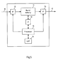
- FIG. 5 a block diagram of a system for bit swapping according to the present invention
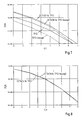
- FIG. 7 a first comparison of the frame error ratios that are achieved by FLO radio packets without bit swapping and by FLO radio packets with bit swapping according to the present invention
- FIG. 8 a second comparison of the frame error ratios that are achieved by FLO radio packets without bit swapping and by FLO radio packets with bit swapping according to the present invention.
- FIG. 3 depicts the structure of a radio packet in the Flexible Layer One (FLO) of GSM/EDGE for the full rate 8-PSK channels.
- Each transport block which contains binary layer 2 data of a Traffic Channel (TrCH)
- CRC Cyclic Redundancy Check
- FIG. 3 only the radio frames 4 - 0 and 4 -(S ⁇ 1), corresponding to TrCH( 0 ) and TrCH(S ⁇ 1), respectively, are shown, where S denotes the number of active TrCHs.
- For each radio packet to be transmitted, one radio frame 4 -s with s 0, . . .
- ⁇ 1 from each active TrCH is delivered to the TrCH multiplexing.
- These radio frames 4 -s are serially multiplexed into a Coded Composite Transport Channel (CCTrCH).
- CCTrCH Coded Composite Transport Channel
- TFCI bits 6 in this example configuration 72 bits, at the beginning of the CCTrCH bits 7 , a non-interleaved radio packet 8 is yield, which comprises a total of 1392 bits.
- the function “int [j]” means rounding down to the next smallest natural number with respect to j, whereas the modulo operator “i mod j” returns the remainder of the division i/j.
- the first column of FIG. 4 shows the index k of the bit within the non-interleaved radio packet 8 before interleaving
- the second column shows the assigned index j within the corresponding burst b after interleaving
- the third column shows the assigned burst index b after interleaving.
- the radio packet then is subject to 8-PSK modulation, which results in every third bit of the radio packet being more error prone than the other bits.
- bit positions k 1, 5, 10, 14, 16, 19, 20, 23, 25, 29, 34, 38, 40, 43, 44, 47, 49, 53, 58, 62, 64, 67, 68 and 71 (also see FIG. 6 ).
- bit k is swapped with bit k+N when cpt is even and with bit k+(K ⁇ N) when cpt is odd, where N is a predetermined natural number and where cpt is a counter that is initialized with zero when starting the swapping procedure and is increased by one after each swapping operation.
- bit k may be swapped with bit k+N irrespective of the value of cpt, which simplifies the procedure, but may increase the bit error ratio of the CCTrCH even further.
- FIG. 5 depicts a block diagram of a system for bit swapping according to the present invention.
- the system comprises a burst memory 11 with interfaces (IF) 12 , 13 and 14 , a processor 15 for controlling the interfaces 12 , 13 and 14 and a look-up-table (LUT) 16 .
- the processor controls the burst-wise storage of bursts of an interleaved radio packet 10 that stems from a previous interleaving stage into the burst memory 11 , which may be implemented as a RAM.
- the processor When the burst is stored in the RAM, the processor, via interface 13 , swaps bits of the stored burst according to the swapping information that is contained in the LUT 16 for the present interleaving scheme and interleaving depth I. Finally, the processor triggers the reading from the burst out of memory 11 via interface 14 . The swapped bursts 17 then are forwarded to a modulator stage.
- the same setup can be used for de-swapping at the receiver, where the incoming bursts are burst-wise stored in the burst memory 11 , de-swapped according to the same LUT 16 as in the swapping case, and subsequently forwarded to a de-interleaving stage.
- FIG. 6 depicts a table that indicates which bits of the TFCI are swapped with bits from the CCTrCH according to the present invention.
- a table may be stored in the LUT 16 of a system for bit swapping as depicted in FIG. 5 .
- FIG. 7 depicts a first comparison of the frame error ratios that are achieved by FLO radio packets without bit swapping and by FLO radio packets with bit swapping according to the present invention.
- the FLO is configured to carry an Adaptive Multirate Codec (AMR) call at 4.75 kbps on 8-PSK channels with 5 bits TFCI (72 bits coded).
- AMR Adaptive Multirate Codec
- TFCI 72 bits coded
- FIG. 7 shows both the Frame Error Ratio (FER) of the radio packet comprising both TFCI and CCTrCH, and the FER of the TFCI alone, in both cases with (dashed line) and without bit swapping (solid line) according to the present invention and as a function of the Carrier-to-Interference Ratio (C/I) in dB.
- FER Frame Error Ratio
- C/I Carrier-to-Interference Ratio
- FIG. 8 depicts a second comparison of the frame error ratios that are achieved by FLO radio packets without bit swapping and by FLO radio packets with bit swapping according to the present invention. Because more weak bits are used for the CCTrCH as a result of the bit swapping, this could cause some loss in performance when many bits are swapped and when the coding rate of the CCTrCH is high, which corresponds to a low error protection.
- the FLO is configured to carry an AMR call at 12.2 kbps on the same channels as in FIG. 7 .
- bit swapping may be performed during the interleaving step, and different interleaving schemes may be applied, in particular with respect to the arrangement of the interleaved bits within a burst.
- the scope of the present invention is by no means restricted to 8-PSK modulation or to the GSM/EDGE system. It may also be applied for instance in spread spectrum or Orthogonal Frequency Division Multiplex (OFDM) systems.
Landscapes
- Engineering & Computer Science (AREA)
- Computer Networks & Wireless Communication (AREA)
- Signal Processing (AREA)
- Quality & Reliability (AREA)
- Theoretical Computer Science (AREA)
- Detection And Prevention Of Errors In Transmission (AREA)
- Error Detection And Correction (AREA)
- Mobile Radio Communication Systems (AREA)
- Digital Transmission Methods That Use Modulated Carrier Waves (AREA)
- Electrophonic Musical Instruments (AREA)
- Prostheses (AREA)
- Materials For Medical Uses (AREA)
- Road Signs Or Road Markings (AREA)
- Data Exchanges In Wide-Area Networks (AREA)
Priority Applications (13)
| Application Number | Priority Date | Filing Date | Title |
|---|---|---|---|
| US10/601,338 US6919829B2 (en) | 2003-06-20 | 2003-06-20 | Bit swapping for different interleaving depths |
| EP04736990A EP1606902B2 (en) | 2003-06-20 | 2004-06-17 | Bit swapping for different interleaving depths |
| JP2006516570A JP4276261B2 (ja) | 2003-06-20 | 2004-06-17 | ビットスワッピングを行う方法、ビットスワッピングを行う装置およびコンピュータプログラム |
| AT04736990T ATE372001T1 (de) | 2003-06-20 | 2004-06-17 | Bitaustausch für verschiedene verschachtelungstiefen |
| CNA2004800148677A CN1799214A (zh) | 2003-06-20 | 2004-06-17 | 用于不同交织深度的比特交换 |
| ES04736990T ES2289523T3 (es) | 2003-06-20 | 2004-06-17 | Intercambio de bits para profundidades de entrelazado diferentes. |
| CA002525883A CA2525883A1 (en) | 2003-06-20 | 2004-06-17 | Bit swapping for different interleaving depths |
| DE202004021657U DE202004021657U1 (de) | 2003-06-20 | 2004-06-17 | Bitaustausch für verschiedene Verschachtelungstiefen |
| DE602004008595T DE602004008595T2 (de) | 2003-06-20 | 2004-06-17 | Bitaustausch für verschiedene verschachtelungstiefen |
| AU2004250807A AU2004250807B2 (en) | 2003-06-20 | 2004-06-17 | Bit swapping for different interleaving depths |
| KR1020057024364A KR100686704B1 (ko) | 2003-06-20 | 2004-06-17 | 상이한 인터리빙 깊이들을 위한 비트 교환 |
| PCT/IB2004/002051 WO2004114580A1 (en) | 2003-06-20 | 2004-06-17 | Bit swapping for different interleaving depths |
| TW093117575A TWI248741B (en) | 2003-06-20 | 2004-06-18 | Method and system for bit swapping |
Applications Claiming Priority (1)
| Application Number | Priority Date | Filing Date | Title |
|---|---|---|---|
| US10/601,338 US6919829B2 (en) | 2003-06-20 | 2003-06-20 | Bit swapping for different interleaving depths |
Publications (2)
| Publication Number | Publication Date |
|---|---|
| US20040257250A1 US20040257250A1 (en) | 2004-12-23 |
| US6919829B2 true US6919829B2 (en) | 2005-07-19 |
Family
ID=33517948
Family Applications (1)
| Application Number | Title | Priority Date | Filing Date |
|---|---|---|---|
| US10/601,338 Expired - Lifetime US6919829B2 (en) | 2003-06-20 | 2003-06-20 | Bit swapping for different interleaving depths |
Country Status (12)
| Country | Link |
|---|---|
| US (1) | US6919829B2 (ja) |
| EP (1) | EP1606902B2 (ja) |
| JP (1) | JP4276261B2 (ja) |
| KR (1) | KR100686704B1 (ja) |
| CN (1) | CN1799214A (ja) |
| AT (1) | ATE372001T1 (ja) |
| AU (1) | AU2004250807B2 (ja) |
| CA (1) | CA2525883A1 (ja) |
| DE (2) | DE202004021657U1 (ja) |
| ES (1) | ES2289523T3 (ja) |
| TW (1) | TWI248741B (ja) |
| WO (1) | WO2004114580A1 (ja) |
Cited By (1)
| Publication number | Priority date | Publication date | Assignee | Title |
|---|---|---|---|---|
| US20100022582A1 (en) * | 2005-03-10 | 2010-01-28 | Kenji Takahashi | Tetrahydroisoquinoline Compound and Medicinal Use Thereof |
Families Citing this family (10)
| Publication number | Priority date | Publication date | Assignee | Title |
|---|---|---|---|---|
| CH694215A5 (de) * | 2003-09-10 | 2004-09-15 | Csaba Bona | Verfahren zum Uebermitteln von elektronischen Daten ueber ein duales Netzwerk zur Erhhoehung der Internetsicherheit. |
| US8077743B2 (en) * | 2003-11-18 | 2011-12-13 | Qualcomm Incorporated | Method and apparatus for offset interleaving of vocoder frames |
| GB0522322D0 (en) * | 2005-11-02 | 2005-12-07 | Siemens Ag | A method of transmitting data |
| KR100987269B1 (ko) * | 2006-08-22 | 2010-10-12 | 삼성전자주식회사 | 이동통신 시스템에서 고차 변조 기반의 버스트 매핑 방법및 장치 |
| CN101933272B (zh) * | 2007-10-01 | 2014-03-19 | 交互数字专利控股公司 | 用于简化redhot a和b无线发射/接收单元的上行链路状态标志(usf)的解码复杂度的方法 |
| US9338475B2 (en) * | 2008-04-16 | 2016-05-10 | Intel Corporation | Tone mapping for bit-depth scalable video codec |
| KR101901954B1 (ko) * | 2009-01-22 | 2018-09-28 | 엘지전자 주식회사 | 신호 송수신 장치 및 방법 |
| US9083495B2 (en) * | 2010-05-06 | 2015-07-14 | Telefonaktiebolaget Lm Ericsson (Publ) | System and method for signaling control information in a mobile communication network |
| CN103973405B (zh) * | 2014-05-13 | 2017-05-24 | 江苏中兴微通信息科技有限公司 | 一种无线通信系统中的符号交织深度优化方法 |
| CN104993902A (zh) * | 2015-02-03 | 2015-10-21 | 协同通信技术有限公司 | 卫星通信系统信道复用的方法 |
Citations (3)
| Publication number | Priority date | Publication date | Assignee | Title |
|---|---|---|---|---|
| WO2000074296A1 (en) | 1999-06-01 | 2000-12-07 | Motorola Inc. | Method and apparatus for mapping bits to an information burst |
| EP1265413A2 (en) | 2001-06-09 | 2002-12-11 | Samsung Electronics Co., Ltd. | Mapping with unequal error protection |
| US6629287B1 (en) * | 1999-09-14 | 2003-09-30 | Agere Systems Inc. | Channel decoder and method of channel decoding |
Family Cites Families (10)
| Publication number | Priority date | Publication date | Assignee | Title |
|---|---|---|---|---|
| US4547887A (en) † | 1983-11-30 | 1985-10-15 | The United States Of America As Represented By The Secretary Of The Army | Pseudo-random convolutional interleaving |
| US5263051A (en) † | 1991-07-05 | 1993-11-16 | Codex Corporation | Device and method of interleaving for a trellis precoding system |
| JPH0775099A (ja) † | 1993-05-07 | 1995-03-17 | Philips Electron Nv | マルチプレックス直交振幅変調テレビジョン送信用送信方式、送信機及び受信機 |
| JP3258022B2 (ja) † | 1993-12-29 | 2002-02-18 | ゼニス、エレクトロニクス コーポレーション | 可変サイズデータ配列のためのデータ・フレーム・フォーマット |
| US5602875A (en) † | 1995-01-13 | 1997-02-11 | Motorola, Inc. | Method and apparatus for encoding and decoding information in a digtial communication system |
| US5796755A (en) † | 1995-10-10 | 1998-08-18 | Eastman Kodak Company | Error minimization in interleaved error correcting codes |
| KR970060721A (ko) † | 1996-01-29 | 1997-08-12 | 이데이 노부유끼 | 지향성패턴의 인터리브 및 변경을 위한 송신장치,수신장치,송신방법 및 수신방법 |
| US6304581B1 (en) † | 1999-02-16 | 2001-10-16 | Motorola, Inc. | Interleaving method and apparatus for orthogonal transmit diversity and multi-carriers CDMA communication systems |
| US6311306B1 (en) † | 1999-04-26 | 2001-10-30 | Motorola, Inc. | System for error control by subdividing coded information units into subsets reordering and interlacing the subsets, to produce a set of interleaved coded information units |
| FI114766B (fi) † | 1999-11-30 | 2004-12-15 | Nokia Corp | Menetelmä ja järjestelmä kehyksen sisäisen lomituksen toteuttamiseksi |
-
2003
- 2003-06-20 US US10/601,338 patent/US6919829B2/en not_active Expired - Lifetime
-
2004
- 2004-06-17 CA CA002525883A patent/CA2525883A1/en not_active Abandoned
- 2004-06-17 KR KR1020057024364A patent/KR100686704B1/ko not_active Expired - Lifetime
- 2004-06-17 WO PCT/IB2004/002051 patent/WO2004114580A1/en not_active Ceased
- 2004-06-17 AT AT04736990T patent/ATE372001T1/de active
- 2004-06-17 DE DE202004021657U patent/DE202004021657U1/de not_active Expired - Lifetime
- 2004-06-17 EP EP04736990A patent/EP1606902B2/en not_active Expired - Lifetime
- 2004-06-17 AU AU2004250807A patent/AU2004250807B2/en not_active Ceased
- 2004-06-17 JP JP2006516570A patent/JP4276261B2/ja not_active Expired - Fee Related
- 2004-06-17 DE DE602004008595T patent/DE602004008595T2/de not_active Expired - Lifetime
- 2004-06-17 ES ES04736990T patent/ES2289523T3/es not_active Expired - Lifetime
- 2004-06-17 CN CNA2004800148677A patent/CN1799214A/zh active Pending
- 2004-06-18 TW TW093117575A patent/TWI248741B/zh not_active IP Right Cessation
Patent Citations (5)
| Publication number | Priority date | Publication date | Assignee | Title |
|---|---|---|---|---|
| WO2000074296A1 (en) | 1999-06-01 | 2000-12-07 | Motorola Inc. | Method and apparatus for mapping bits to an information burst |
| US6259744B1 (en) * | 1999-06-01 | 2001-07-10 | Motorola, Inc. | Method and apparatus for mapping bits to an information burst |
| US6629287B1 (en) * | 1999-09-14 | 2003-09-30 | Agere Systems Inc. | Channel decoder and method of channel decoding |
| EP1265413A2 (en) | 2001-06-09 | 2002-12-11 | Samsung Electronics Co., Ltd. | Mapping with unequal error protection |
| US20020186784A1 (en) | 2001-06-09 | 2002-12-12 | Samsung Electronics Co., Ltd. | Method and apparatus for rearranging codeword sequence in a communication system |
Non-Patent Citations (6)
| Title |
|---|
| 3GPP TR 45.902 V6.0.0 (Apr. 2003), 3rd Generation Partnership Project; Technical Specification Group GSM/EDGE. |
| 3GPP TS 45.003 V5.6.0 (2202-06), 3rd Generation, Partnership Project; Technical Specification Group GSM/EDGE, not date given. |
| 3GPP TS 45.004 V5.1.0 (Jun. 2002), 3rd Generation Partnership Project; Technical Specification Group. |
| GSM/EDGE Radio Access Network; Modulation (Release 4), no date. |
| Radio Access Network; Channel coding (Release 5), no date given. |
| Radio Access Network; Flexible Layer One; (Release 6), no date. |
Cited By (1)
| Publication number | Priority date | Publication date | Assignee | Title |
|---|---|---|---|---|
| US20100022582A1 (en) * | 2005-03-10 | 2010-01-28 | Kenji Takahashi | Tetrahydroisoquinoline Compound and Medicinal Use Thereof |
Also Published As
| Publication number | Publication date |
|---|---|
| TW200503489A (en) | 2005-01-16 |
| JP4276261B2 (ja) | 2009-06-10 |
| ES2289523T3 (es) | 2008-02-01 |
| DE602004008595D1 (de) | 2007-10-11 |
| DE202004021657U1 (de) | 2009-12-03 |
| KR100686704B1 (ko) | 2007-02-26 |
| EP1606902B1 (en) | 2007-08-29 |
| JP2007520907A (ja) | 2007-07-26 |
| EP1606902A1 (en) | 2005-12-21 |
| TWI248741B (en) | 2006-02-01 |
| AU2004250807B2 (en) | 2008-11-20 |
| EP1606902B2 (en) | 2010-06-16 |
| KR20060020690A (ko) | 2006-03-06 |
| ATE372001T1 (de) | 2007-09-15 |
| CA2525883A1 (en) | 2004-12-29 |
| DE602004008595T2 (de) | 2007-12-27 |
| AU2004250807A1 (en) | 2004-12-29 |
| DE202004021657U8 (de) | 2010-05-12 |
| WO2004114580A1 (en) | 2004-12-29 |
| US20040257250A1 (en) | 2004-12-23 |
| CN1799214A (zh) | 2006-07-05 |
Similar Documents
| Publication | Publication Date | Title |
|---|---|---|
| US5533004A (en) | Method for providing and selecting amongst multiple data rates in a time division multiplexed system | |
| EP1101314B1 (en) | Method and apparatus for mapping bits to an information burst | |
| US8135082B2 (en) | High-order modulation-based burst mapping method and apparatus in a mobile communication system | |
| US6311306B1 (en) | System for error control by subdividing coded information units into subsets reordering and interlacing the subsets, to produce a set of interleaved coded information units | |
| US20030171121A1 (en) | Apparatus and method for performing coding and rate matching in a CDMA mobile communication system | |
| AU3139602A (en) | Apparatus and method for transmitting/receiving data in a CDMA mobile communication system | |
| EP1352478B1 (en) | Method and system for allocating convolutional encoded bits into symbols before modulation | |
| WO2021180236A1 (en) | Modulation and binary convolutional coding for mutiple resource units in wireless network | |
| EP1803286B1 (en) | A method for the selection of forward error correction (fec)/ constellation pairings for digital transmitted segments based on learning radio link adaptation (rla) | |
| US6684366B1 (en) | Multi-rate codec with puncture control | |
| US6919829B2 (en) | Bit swapping for different interleaving depths | |
| US6870821B2 (en) | Flexible layer overlay for seamless handovers between full rate and half rate channels | |
| EP1554866B1 (en) | Method for rate matching to support incremental redundancy with flexible layer one | |
| KR20010080386A (ko) | 링크 적응 및 증가하는 중복을 지원하는 무선 통신을 위한시스템 및 방법 | |
| US8542624B2 (en) | Method of transmitting signal | |
| HK1091625A (en) | Bit swapping for different interleaving depths | |
| AU2003259591A1 (en) | Apparatus and method for transmitting/receiving data in a CDMA mobile communication system |
Legal Events
| Date | Code | Title | Description |
|---|---|---|---|
| AS | Assignment |
Owner name: NOKIA CORPORATION, FINLAND Free format text: ASSIGNMENT OF ASSIGNORS INTEREST;ASSIGNOR:SEBIRE, BENOIST;REEL/FRAME:014872/0587 Effective date: 20030724 |
|
| STCF | Information on status: patent grant |
Free format text: PATENTED CASE |
|
| FEPP | Fee payment procedure |
Free format text: PAYOR NUMBER ASSIGNED (ORIGINAL EVENT CODE: ASPN); ENTITY STATUS OF PATENT OWNER: LARGE ENTITY |
|
| FPAY | Fee payment |
Year of fee payment: 4 |
|
| FPAY | Fee payment |
Year of fee payment: 8 |
|
| AS | Assignment |
Owner name: NOKIA TECHNOLOGIES OY, FINLAND Free format text: ASSIGNMENT OF ASSIGNORS INTEREST;ASSIGNOR:NOKIA CORPORATION;REEL/FRAME:035495/0924 Effective date: 20150116 |
|
| FPAY | Fee payment |
Year of fee payment: 12 |