US6833704B1 - Multinuclear wands - Google Patents
Multinuclear wands Download PDFInfo
- Publication number
- US6833704B1 US6833704B1 US10/624,744 US62474403A US6833704B1 US 6833704 B1 US6833704 B1 US 6833704B1 US 62474403 A US62474403 A US 62474403A US 6833704 B1 US6833704 B1 US 6833704B1
- Authority
- US
- United States
- Prior art keywords
- probe
- wand
- adjustable
- electrical
- wave
- Prior art date
- Legal status (The legal status is an assumption and is not a legal conclusion. Google has not performed a legal analysis and makes no representation as to the accuracy of the status listed.)
- Expired - Fee Related
Links
Images


Classifications
-
- G—PHYSICS
- G01—MEASURING; TESTING
- G01R—MEASURING ELECTRIC VARIABLES; MEASURING MAGNETIC VARIABLES
- G01R33/00—Arrangements or instruments for measuring magnetic variables
- G01R33/20—Arrangements or instruments for measuring magnetic variables involving magnetic resonance
- G01R33/28—Details of apparatus provided for in groups G01R33/44 - G01R33/64
- G01R33/32—Excitation or detection systems, e.g. using radio frequency signals
- G01R33/36—Electrical details, e.g. matching or coupling of the coil to the receiver
- G01R33/3628—Tuning/matching of the transmit/receive coil
- G01R33/3635—Multi-frequency operation
Definitions
- This invention is in the field of nuclear magnetic resonance (NMR) apparatus and relates to an adjustable plug-in wand to facilitate either single-frequency operation or multi-nuclei operation of the probe wherein the particular choice of nuclei is determined by the plug-in wand.
- NMR nuclear magnetic resonance
- NMR spectrometers typically include a probe containing the sample to be analyzed, a superconducting magnet for generating a static magnetic field B 0 , and console unit containing the electronic equipment needed to operate the spectrometer system.
- the probe contains one or more radio-frequency (RF) coils surrounding the sample for generating time-varying magnetic fields B 1 perpendicular to the static magnetic field B 0 .
- RF radio-frequency
- the multiple tuning of the probe is achieved with the aid of one or more additional RF coils and capacitors that are removed physically from the RF coils containing the NMR sample.
- a spectrometer system is designed to detect protons and deuterium, which is used for set-up and spectrometer frequency control. These two frequencies may be provided by one RF coil by double tuning. Another coil disposed at right angles to this first coil may be double tuned to detect phosphorus-31 and carbon-13. It is often desirable to use the same probe to detect a different second set of nuclei, for example sodium-23 and chlorene-35.
- Existing probes are generally constructed to operate on a pre-selected one or two frequencies (in addition to protons and deuterium), therefore two or more probes are needed for applications requiring up to four additional frequencies.
- a capacitor switch is activated upon insertion of a capacitor stick.
- a 1 ⁇ 4 wave stick incorporating a metallic threaded screw that closes a threaded connection switch thereby connecting capacitors internal to the probe and the 1 ⁇ 4 wave center connector of the switch to operate cooperatively to permit double frequency operation.
- an extension stick is used in place of the 1 ⁇ 4 wave stick and an external section of wave tube is mounted on the extension stick wherein part of the wave tube is in the probe and part on the stick. For each pair of additional frequencies a different stick and extension tube is required.
- the wands for double frequency operation have one or more capacitors and a central conducting rod with an adjustable conductive collar having spring finger contacts that in cooperation with a conducting tube form an adjustable 1 ⁇ 4 wave stub and produce double tune operation.
- the tube may either be fixed to the wand or to the probe.
- Wands for different set of double frequencies contain capacitors with different values and with the conductive collar set to different positions.
- the wands for different single frequencies or different sets of double frequencies may be identical in their construction making them easier to construct.
- the values selected for capacitors within the wand, the way of their connection, and the position of the adjustable collar determine the different frequencies.
- Single frequency operation is obtained by different electrical connections within the wand.
- clips hold the capacitors, permitting them to be changed.
- An electrical jumper may be used in place of a capacitor, or the clip may be left vacant thereby, changing the circuit configuration.
- the insertion of the wand into the probe requires no turning or rotating.
- the wand is inserted directly in the probe: the end of the wand plugs into a keyed electrical socket within the probe.
- the electrical plug and socket permits changing the probe configuration and operating frequencies, without requiring the wand to be rotated. All the wands can be of the same size and length and still have means for providing for different resonant frequencies of the 1 ⁇ 4 wave shorted stub.
- An additional feature of the present invention is the low manufacturing cost of the probe and wand, as the mechanical parts of all probes and wands are identical.
- the electrical socket within the probe and mating electrical plug on the wand provides a low cost method of electrically coupling the wand to the probe.
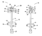
- FIG. 1A schematically shows a 1 ⁇ 4 wave assembly component contained in a wand.
- FIG. 1B is a detailed view of a conductive collar part of the wand.
- FIG. 1C schematically shows a conductive tube surrounding the 1 ⁇ 4 wand assembly.
- FIG. 2A schematically shows clips used to make electrical contact and retain the capacitors and/or conducting jumpers within the wand.
- FIG. 2B is a side view of a pair of clips connecting to, and mechanically supporting, a capacitor.
- FIG. 3 schematically shows a conductive tube attached to an electrical socket which is located within the probe that receives the wand.
- FIG. 4 schematically shows an electrical circuit contained within the wand.
- FIG. 5 schematically shows the electrical circuits contained in the probe.
- FIG. 6A is a schematic of a first circuit configuration within the wand for single frequency operation.
- FIG. 6B is a circuit of the equivalent circuit for a probe and wand, with the wand configuration of FIG. 6 A.
- FIG. 7A is a schematic of a second circuit configuration within the wand for single frequency operation at a lower frequency.
- FIG. 7B is a circuit of the equivalent circuit for a probe and wand, with the wand configuration of FIG. 7 A.
- FIG. 8A is a schematic of a first circuit configuration within the wand for double frequency operation.
- FIG. 8B is a circuit of the equivalent circuit for a probe and wand, with the wand configuration of FIG. 8 A.
- FIG. 9A is a schematic of a second circuit configuration within the wand for double frequency operation.
- FIG. 9B is a circuit of the equivalent circuit for a probe and wand, with the wand configuration of FIG. 9 A.
- FIG. 1A illustrates the adjustable wand 10 used to select the frequency range of operation of a probe and thereby select the particular nuclei the probe will detect. It determines whether the RF probe coil tunes to a single frequency or is tuned to two frequencies. Double frequency operation is achieved using a 1 ⁇ 4 wave assembly.
- the 1 ⁇ 4 wave assembly comprises conducting rod 11 , shorting stub 12 and conducting tube 37 of FIG. 1 C.
- Shorting stub 12 comprises collar 13 , spring contact 15 , and set screw 17 .
- Conducting rod 11 and collar 13 are made of metals with high electrical conductivity such as copper or aluminum.
- Spring contact 15 may consist of a helical wound coil spring made of a non-magnetic spring metal such as phosphor bronze or non-magnetic stainless steel.
- FIG. 1B is a plan view of collar 13 and spring contact 15 .
- the spring loops are compressed making good electrical contact between collar 13 and conducting tube 37 .
- a series of spring contact fingers could be used to provide electrical contact between collar 13 and conducting tube 37 of FIG. 1C.
- a handle 27 is located at the lower end of conducting rod 11 to facilitate the insertion of the wand into the probe.
- the upper end of conducting rod 11 supports platform 19 and electrical plug 20 .
- Electrical plug 20 comprise pins 21 , 22 , 23 (labeled 1 , 2 , and 3 respectively) and insulating plug body 25 .
- the geometrical arrangement of the pins is such that there is only one orientation in which pins will match the corresponding socket on the probe.
- Platform 19 is made of a dielectric material and is fixed to the end of conducting rod 11 . Platform 19 supports up to three capacitors 31 , 32 , 33 .
- electrical jumpers replace one or more capacitors or one or more capacitors are left out with no connection as is explained below.
- Capacitor 31 is connected between pin 21 and conducting rod 11 ; capacitor 32 between pins 21 and 22 ; capacitor 33 between pin 23 and conducting rod 1 .
- a dielectric rod replaces conducting rod 11 , and in this case one side of capacitors 31 and 33 are still connected together.
- FIG. 1C is a perspective view of a preferred embodiment wherein conducting tube 37 is fixed to wand 10 .
- the position of conductive collar 13 is first adjusted to the required position and then conductive tube 37 is slipped over wand 10 and secured by machine screws 36 threaded into insulating plug body 25 of electrical plug 20 .
- FIG. 2A is a preferred embodiment incorporating an electrical printed circuit 64 printed on platform 19 .
- Small spring clips 60 hold capacitor 31 , 32 , and 33 in place and provide electrical contact to them.
- FIG. 2B is a side view showing capacitor 32 supported by two spring clips 60 .
- Spring clips 60 are soldered or otherwise fixed to printed circuit 64 .
- Electrical contact is provided by extension of plug pins 21 , 22 , and 23 down through holes 61 , 62 , and 63 respectively, where a solder connection is made to the printed circuit 64 .
- one or more clips are left empty, and some clips require an electrical jumper (not shown) to be inserted in place of one or more capacitors.
- the jumper is a metal object with the same dimensions as a capacitor so it fits within the same space and can be held by clips 60 , to provide a low resistance connection between the two clips.
- Specific circuit configurations of the wand are shown in FIGS. 6A through 9B.
- the spring clip mountings permit the wand configuration to be easily changed.
- surface amount capacitors may be used and soldered directly to the printed circuit eliminating the need for spring clips 60 .
- electrical jumpers may also be soldered directly to the printed circuit, or the connection may be left open.
- FIG. 3 is preferred embodiment wherein conducting tube 37 is fixed to electrical socket 38 , which is mounted in the probe.
- Electrical socket 38 comprises connector receptacles 41 , 42 and 43 (labeled 1 , 2 , and 3 ) keyed to receive respective pins 21 , 22 and 23 of electrical plug 20 .
- Connector receptacles 41 , 42 , and 43 are held in place by insulating material 39 of electrical socket 38 .
- Conducting tube 37 is fixed to electrical socket 38 by machine screws 36 that screw into tapped holes in insulating material 39 .
- Conducting tube 37 is a metal tube made of copper or some other metal of high electrical conductivity. Electrical connection is made between conducting tube 37 and connector receptacle 43 (See FIG. 5 ).
- spring 15 establishes a low conductivity electrical connection tube 37 and collar 13 and in cooperation with conducting rod 11 form a 1 ⁇ 4 wave shorted stub.
- FIG. 4 is a schematic diagram of the electrical circuit within the wand 10 showing capacitors 31 , 32 , 33 and their connections to pins 21 , 22 , 23 (labeled 1 , 2 , 3 on the plug) and to rod 11 .
- spring clip connectors 60 are used to hold the capacitors and to permit their ease of replacement, and for the insertion of an electrical jumper in the place of a capacitor, and for the establishment of an electrical open circuit.
- FIG. 5 a schematic diagram of the probe incorporating conducting tube 37 with electrical socket 3 S that receives the wand plug and the remaining electrical circuit of the probe.
- the NMR sample is contained in within NMR probe coil 45 that is located in the magnet in the region containing the most homogeneous magnetic field B 0 .
- the outer shell of conducting tube 37 and connector receptacle 43 are connected to probe ground 50 . (If the conducting tube 37 is mounted on the wand its electrical ground is established tough pin 23 which plugs into connector receptacle 43 and thereby to probe ground 50 ).
- One terminal of circuit variable capacitor Cs 47 and one terminal of wave variable capacitor Ct 46 are connected to probe ground 50 .
- Input and out signals from and to the console are made via a coaxial cable connected to probe cable connector 49 .
- Shield connection 51 of probe cable connector 49 goes to probe ground 50
- the electrically active center wire 52 connects to one side of match variable capacitor Cm 48 .
- the other terminal of match variable capacitor Cm 48 connects to the ungrounded terminal of circuit tune capacitor Cs 47 , to connector receptacle 42 and to the probe coil 45 .
- the other side of probe coil 45 is connected to the ungrounded terminal of wave variable capacitor 46 , and to connector receptacle 41 .
- connection arrangement contained in the wand determines whether single frequency of double frequency operation is selected and the values of capacitors contained in the wand determines which nuclei will be detected by the probe.
- the following figures illustrate how single and double frequency operation is determined and the capacitors that determine the operating frequencies.
- FIGS. 6A-B and 7 A-B show the connection arrangement for single frequency operation and FIGS. 8A-B and 9 A-B for double frequency operation.
- FIG. 6A Single frequency operation of FIG. 6A is achieved by placing electrical jumpers 131 and 133 in place of capacitor 31 and 33 of FIG. 4 . Connections to the probe are made through pins 21 , 22 , 23 (labeled 1 , 2 , 3 respectively). The circuit is left open in place capacitor 32 of FIG. 4 . This combination of connections within the wand when inserted into the probe yields a first circuit configuration for single frequency operation.
- FIG. 6B is the electrical circuit resulting from the connections selected in FIG. 6 A.
- the 1 ⁇ 4 wave shorted stub is not in the circuit, and is in fact shorted out by jumper 133 of FIG. 6 A.
- a non-conducting rod 111 could replace conducting rod 11 as it does not enter the circuit.
- Collar 13 with spring contact 15 may also be eliminated.
- Conducting tube 37 may also be eliminated in the embodiment where tube 37 is normally attached to plug insulator 25 of wand 10 .
- NMR probe coil 45 is tuned by capacitor Cs 47 and matched by capacitor Cm 48 .
- Connection to the console (not shown) are make through coaxial cable connector 49 . Shield connection of connector 49 is attached to probe ground 50 .
- FIG. 7A is an alternative wand configuration for single frequency operation. It is identical to the wand of FIG. 6A with the change that capacitor 32 is fixed therein. Capacitor 32 is introduced in place of the empty clip of FIG. 6 A. This has the property of lowering the resonant frequency of the Probe. For example, at a field strength of 9.4 T (400 MHz proton field), the circuit of FIG. 6B might be tuned for phosphorus 31 at 162 MHz. Carbon 13 at 100.6 MHz could be observed with the same probe using the wand of FIG. 7A by proper choice of capacitor 32 . In this configuration 1 ⁇ 4 wave shorted stub is not in the circuit being shorted out by electrical jumper 133 .
- FIG. 7B shows capacitor 32 is in parallel with circuit variable capacitor Cs 47 .
- the other components of FIG. 7B are identical with those of FIG. 6B, with NMR probe coil 45 , matching capacitor Cm 48 , connector 49 and ground 50 .
- FIG. 8A is a wand configuration for a double tuned circuit.
- the jumper 133 of FIG. 7A is removed thereby unshorting the 1 ⁇ 4 wave structure
- Capacitors 31 and 33 optimize the coupling of the 1 ⁇ 4 wave structure to the probe circuit pins 21 , 22 , 23 (labeled 1 , 2 , 3 respectively) provide coupling between the wand and the probe circuit.
- FIG. 8B is the equivalent circuit for the combination of wand configuration of FIG. 8 A and the probe circuit (FIG. 4 ). In this configuration length of the 1 ⁇ 4 wave shorted stub is adjusted by moving shorting stub 12 (FIG. 1 A).
- Wave variable capacitor Ct 46 This is done by loosening set screw 17 and moving collar up or down on rod 11 to the desired position and then tightening set screw 17 (FIG. 1A, 4 ). Further adjustment is achieved by wave variable capacitor Ct 46 .
- Conducting rod 11 , shorting stub 12 and conducting tube 37 comprize a 1 ⁇ 4 wave structure. Capacitors 31 and 33 optimize the coupling of the 1 ⁇ 4 wave structure to the probe circuit.
- Probe circuit further comprizes NMR probe coil 45 , wave variable capacitor Ct 46 , circuit variable capacitor Cs 47 and match variable capacitor Cm 48 . Connection to the console (not shown) is made through coaxial cable connector 49 . Probe ground connections 50 are made connector 49 , conducting tube 37 , and capacitors 33 , Ct 46 , and Cs 47 .
- FIG. 9A is an alternative wand configuration for a double timed circuit.
- Capacitor 32 is introduced in place of the empty clip of FIG. 8 A.
- the other components of FIG. 9 A and their labeling is unchanged from FIG. 8 A.
- the additional capacitor 32 has the property of lowering the resonant
- FIG. 9B shows capacitor 32 is in parallel NMR probe coil 45 .
- the other components of FIG. 9 B and their labelings are unchanged from FIG. 8 B.
Landscapes
- Physics & Mathematics (AREA)
- Condensed Matter Physics & Semiconductors (AREA)
- General Physics & Mathematics (AREA)
- Magnetic Resonance Imaging Apparatus (AREA)
- Other Investigation Or Analysis Of Materials By Electrical Means (AREA)
Priority Applications (5)
| Application Number | Priority Date | Filing Date | Title |
|---|---|---|---|
| US10/624,744 US6833704B1 (en) | 2003-07-21 | 2003-07-21 | Multinuclear wands |
| DE602004026070T DE602004026070D1 (de) | 2003-07-21 | 2004-06-21 | Mehrfachresonanter nmr-probenkopf mit abnehmbarem viertelwellenlängen-element mit einstellbarer elektrischer länge |
| EP04755810A EP1651973B1 (de) | 2003-07-21 | 2004-06-21 | Mehrfachresonanter nmr-probenkopf mit abnehmbarem viertelwellenlängen-element mit einstellbarer elektrischer länge |
| PCT/US2004/019899 WO2005010545A1 (en) | 2003-07-21 | 2004-06-21 | Multinuclear nmr probe with detachable quarter wavelenght element with adjustable electrical lenght |
| JP2006521075A JP4572196B2 (ja) | 2003-07-21 | 2004-06-21 | 電気的長さを調節可能な着脱可能な4分の1波長素子を有する多核nmrプローブ |
Applications Claiming Priority (1)
| Application Number | Priority Date | Filing Date | Title |
|---|---|---|---|
| US10/624,744 US6833704B1 (en) | 2003-07-21 | 2003-07-21 | Multinuclear wands |
Publications (1)
| Publication Number | Publication Date |
|---|---|
| US6833704B1 true US6833704B1 (en) | 2004-12-21 |
Family
ID=33511901
Family Applications (1)
| Application Number | Title | Priority Date | Filing Date |
|---|---|---|---|
| US10/624,744 Expired - Fee Related US6833704B1 (en) | 2003-07-21 | 2003-07-21 | Multinuclear wands |
Country Status (5)
| Country | Link |
|---|---|
| US (1) | US6833704B1 (de) |
| EP (1) | EP1651973B1 (de) |
| JP (1) | JP4572196B2 (de) |
| DE (1) | DE602004026070D1 (de) |
| WO (1) | WO2005010545A1 (de) |
Cited By (7)
| Publication number | Priority date | Publication date | Assignee | Title |
|---|---|---|---|---|
| US20050027190A1 (en) * | 2003-07-31 | 2005-02-03 | Chiodo Chris D. | Positioning assembly for magnet coils and specimens |
| US20050040823A1 (en) * | 2002-04-14 | 2005-02-24 | Bernhard Blumich | NMR probe for material analysis |
| US7023210B1 (en) * | 2004-10-14 | 2006-04-04 | Varian, Inc. | NMR systems employing inverted variable capacitors |
| US20070013378A1 (en) * | 2005-07-15 | 2007-01-18 | Jeol Ltd. | NMR probe |
| CN106596671A (zh) * | 2016-12-25 | 2017-04-26 | 厦门大学 | 模块化固相可变温电化学核磁共振联用探头杆 |
| US20170317433A1 (en) * | 2016-04-27 | 2017-11-02 | Thomas & Betts International Llc | Through roof connector assembly |
| CN111896900A (zh) * | 2020-07-06 | 2020-11-06 | 苏州佳祺仕信息科技有限公司 | 一种多探头高斯检测设备 |
Families Citing this family (3)
| Publication number | Priority date | Publication date | Assignee | Title |
|---|---|---|---|---|
| JP5020552B2 (ja) * | 2005-07-15 | 2012-09-05 | 株式会社 Jeol Resonance | Nmrプローブ |
| DE102017211401B3 (de) * | 2017-07-04 | 2018-10-18 | Bruker Biospin Ag | Anpassungseinrichtung für einen HF-Resonanzkreis eines NMR-Probenkopfs |
| EP3514561A1 (de) * | 2018-01-18 | 2019-07-24 | Koninklijke Philips N.V. | Rf-spule für mehrkanal-magnetresonanzbildgebung |
Citations (11)
| Publication number | Priority date | Publication date | Assignee | Title |
|---|---|---|---|---|
| US3624508A (en) | 1968-10-15 | 1971-11-30 | Patelhold Patentverwertung | Unitary microwave transmit-receive duplex system with coaxial ring hybrid transformer |
| US4881034A (en) | 1988-01-19 | 1989-11-14 | The Regents Of The University Of California | Switchable MRI RF coil array with individual coils having different and overlapping fields of view |
| US4996482A (en) * | 1988-09-22 | 1991-02-26 | Jeol Ltd. | Capacitor stick for NMR probe |
| US5166617A (en) | 1991-01-11 | 1992-11-24 | Varian Associates, Inc. | High power NMR probe |
| US5390673A (en) * | 1994-01-14 | 1995-02-21 | Cordata, Incorporated | Magnetic resonance imaging system |
| US5552710A (en) | 1994-08-12 | 1996-09-03 | Spectrospin Ag | Method and automatic auxiliary device for tuning of an NMR receiving coil |
| US5768089A (en) | 1997-01-10 | 1998-06-16 | Varian Associates, Inc. | Variable external capacitor for NMR probe |
| US5982179A (en) | 1997-06-04 | 1999-11-09 | Varian, Inc. | NMR circuit-switch |
| US6081120A (en) | 1998-05-20 | 2000-06-27 | Shen; Gary G | Universal-multi-layered, multi-tuned RF probe for MRI and MRS |
| US20020040185A1 (en) * | 1996-04-25 | 2002-04-04 | Ergin Atalar | Systems and methods for evaluating the urethra and the periurethral tissues |
| US20020161421A1 (en) * | 2000-11-20 | 2002-10-31 | Chris Lee | Connector and guidewire connectable thereto |
Family Cites Families (6)
| Publication number | Priority date | Publication date | Assignee | Title |
|---|---|---|---|---|
| JPH01293858A (ja) * | 1988-05-20 | 1989-11-27 | Toshiba Corp | Rfコイル装置 |
| DE4002160A1 (de) * | 1990-01-25 | 1991-08-08 | Bruker Analytische Messtechnik | Probenkopf fuer kernresonanzmessungen und verfahren zur messung von kernresonanzen |
| EP0579473B1 (de) * | 1992-07-14 | 1998-11-04 | Varian Associates, Inc. | Abstimmbare Hochfrequenz-Sonde für magnetische Kernresonanz-Spektroskopie-Untersuchungen und Abstimmungsverfahren |
| EP0930511B1 (de) * | 1998-01-15 | 2006-06-21 | Varian, Inc. | Einstellbare externe Kapazität für NMR-Sonde |
| DE19833350C1 (de) * | 1998-07-24 | 2000-03-09 | Bruker Analytik Gmbh | Probenkopf für Kernresonanzmessungen |
| US6380742B1 (en) * | 2001-07-27 | 2002-04-30 | Varian, Inc. | Balanced mode operation of a high frequency NMR probe |
-
2003
- 2003-07-21 US US10/624,744 patent/US6833704B1/en not_active Expired - Fee Related
-
2004
- 2004-06-21 EP EP04755810A patent/EP1651973B1/de not_active Expired - Fee Related
- 2004-06-21 JP JP2006521075A patent/JP4572196B2/ja not_active Expired - Fee Related
- 2004-06-21 DE DE602004026070T patent/DE602004026070D1/de active Active
- 2004-06-21 WO PCT/US2004/019899 patent/WO2005010545A1/en active Application Filing
Patent Citations (12)
| Publication number | Priority date | Publication date | Assignee | Title |
|---|---|---|---|---|
| US3624508A (en) | 1968-10-15 | 1971-11-30 | Patelhold Patentverwertung | Unitary microwave transmit-receive duplex system with coaxial ring hybrid transformer |
| US4881034A (en) | 1988-01-19 | 1989-11-14 | The Regents Of The University Of California | Switchable MRI RF coil array with individual coils having different and overlapping fields of view |
| US4996482A (en) * | 1988-09-22 | 1991-02-26 | Jeol Ltd. | Capacitor stick for NMR probe |
| US5166617A (en) | 1991-01-11 | 1992-11-24 | Varian Associates, Inc. | High power NMR probe |
| US5390673A (en) * | 1994-01-14 | 1995-02-21 | Cordata, Incorporated | Magnetic resonance imaging system |
| US5552710A (en) | 1994-08-12 | 1996-09-03 | Spectrospin Ag | Method and automatic auxiliary device for tuning of an NMR receiving coil |
| US20020040185A1 (en) * | 1996-04-25 | 2002-04-04 | Ergin Atalar | Systems and methods for evaluating the urethra and the periurethral tissues |
| US5768089A (en) | 1997-01-10 | 1998-06-16 | Varian Associates, Inc. | Variable external capacitor for NMR probe |
| US5982179A (en) | 1997-06-04 | 1999-11-09 | Varian, Inc. | NMR circuit-switch |
| US6081120A (en) | 1998-05-20 | 2000-06-27 | Shen; Gary G | Universal-multi-layered, multi-tuned RF probe for MRI and MRS |
| US20020161421A1 (en) * | 2000-11-20 | 2002-10-31 | Chris Lee | Connector and guidewire connectable thereto |
| US6714809B2 (en) * | 2000-11-20 | 2004-03-30 | Surgi-Vision, Inc. | Connector and guidewire connectable thereto |
Cited By (13)
| Publication number | Priority date | Publication date | Assignee | Title |
|---|---|---|---|---|
| US20050040823A1 (en) * | 2002-04-14 | 2005-02-24 | Bernhard Blumich | NMR probe for material analysis |
| US7095230B2 (en) * | 2002-04-14 | 2006-08-22 | Bernhard Blumich | NMR probe for material analysis |
| US20050027190A1 (en) * | 2003-07-31 | 2005-02-03 | Chiodo Chris D. | Positioning assembly for magnet coils and specimens |
| US7414403B2 (en) * | 2003-07-31 | 2008-08-19 | Chiodo Chris D | Imaging machine / MRI positioning assembly for magnet coils and specimens at the sweet spot of an imaging field |
| US7023210B1 (en) * | 2004-10-14 | 2006-04-04 | Varian, Inc. | NMR systems employing inverted variable capacitors |
| US20060082372A1 (en) * | 2004-10-14 | 2006-04-20 | Varian, Inc. | Nmr systems employing inverted variable capacitors |
| US7378850B2 (en) * | 2005-07-15 | 2008-05-27 | Jeol Ltd. | NMR probe |
| US20070013378A1 (en) * | 2005-07-15 | 2007-01-18 | Jeol Ltd. | NMR probe |
| US20170317433A1 (en) * | 2016-04-27 | 2017-11-02 | Thomas & Betts International Llc | Through roof connector assembly |
| US10074915B2 (en) * | 2016-04-27 | 2018-09-11 | Thomas & Betts International Llc | Through roof connector assembly |
| CN106596671A (zh) * | 2016-12-25 | 2017-04-26 | 厦门大学 | 模块化固相可变温电化学核磁共振联用探头杆 |
| CN106596671B (zh) * | 2016-12-25 | 2018-12-14 | 厦门大学 | 模块化固相可变温电化学核磁共振联用探头杆 |
| CN111896900A (zh) * | 2020-07-06 | 2020-11-06 | 苏州佳祺仕信息科技有限公司 | 一种多探头高斯检测设备 |
Also Published As
| Publication number | Publication date |
|---|---|
| EP1651973B1 (de) | 2010-03-17 |
| EP1651973A1 (de) | 2006-05-03 |
| JP4572196B2 (ja) | 2010-10-27 |
| WO2005010545A1 (en) | 2005-02-03 |
| DE602004026070D1 (de) | 2010-04-29 |
| JP2006528349A (ja) | 2006-12-14 |
Similar Documents
| Publication | Publication Date | Title |
|---|---|---|
| US5371466A (en) | MRI RF ground breaker assembly | |
| US4621237A (en) | Radiofrequency transducer and method of using same | |
| CN100554993C (zh) | 用于超高场(shf)mri的rf线圈系统 | |
| US8049504B2 (en) | Simple decoupling of a multi-element RF coil, enabling also detuning and matching functionality | |
| US7345481B2 (en) | Hybrid TEM/birdcage coil for MRI | |
| CN101454685B (zh) | 解调谐射频线圈 | |
| CN101268379A (zh) | 用于在mri中使用的射频线圈的rf陷波器 | |
| CN101023369A (zh) | 具有紧凑感应组件的磁共振接收线圈 | |
| US6833704B1 (en) | Multinuclear wands | |
| JPS62112542A (ja) | 磁気共振映像装置用高周波コイル | |
| US5699802A (en) | Mammography antenna arrangement for NMR examinations of a female breast | |
| KR19990076807A (ko) | 안테나 어댑터 | |
| CN1954230A (zh) | 用于超高磁场mr的短元件tem线圈 | |
| US5606259A (en) | Adaptable antenna for a magnetic resonance apparatus including a wiper contact for varying the size of the antenna without frequency change | |
| JPH05269104A (ja) | ローカルアンテナ | |
| US6794874B2 (en) | Multiple tuning circuit and probe having multiple tuning circuit for NMR spectrometer | |
| CN1910468B (zh) | 通过选择性插入导电调谐元件进行调谐的射频陷波器 | |
| US5180982A (en) | Probehead for a nuclear magnetic resonance spectrometer | |
| US5850143A (en) | Antenna system for a diagnostic magnetic resonance apparatus | |
| JP4575950B2 (ja) | Nmr用コンデンサスイッチ | |
| US8125226B2 (en) | Millipede surface coils | |
| EP0191180B1 (de) | Gerät zur Bildgebung von gabelförmigen Körperregionen mittels magnetischer Resonanz | |
| US5572128A (en) | Double resonance antenna arrangement for a nuclear magnetic resonance apparatus | |
| US7023210B1 (en) | NMR systems employing inverted variable capacitors | |
| US10557899B2 (en) | Adjustment device for an RF resonant circuit of an NMR probe head |
Legal Events
| Date | Code | Title | Description |
|---|---|---|---|
| AS | Assignment |
Owner name: VARIAN, INC., CALIFORNIA Free format text: ASSIGNMENT OF ASSIGNORS INTEREST;ASSIGNORS:MURPHY, JOSEPH;ANDERSON, WESTON;FINNIGAN, JAMES;REEL/FRAME:014329/0036;SIGNING DATES FROM 20030717 TO 20030721 |
|
| FPAY | Fee payment |
Year of fee payment: 4 |
|
| REMI | Maintenance fee reminder mailed | ||
| AS | Assignment |
Owner name: AGILENT TECHNOLOGIES, INC., CALIFORNIA Free format text: ASSIGNMENT OF ASSIGNORS INTEREST;ASSIGNOR:VARIAN, INC.;REEL/FRAME:025368/0230 Effective date: 20101029 |
|
| FPAY | Fee payment |
Year of fee payment: 8 |
|
| REMI | Maintenance fee reminder mailed | ||
| LAPS | Lapse for failure to pay maintenance fees | ||
| STCH | Information on status: patent discontinuation |
Free format text: PATENT EXPIRED DUE TO NONPAYMENT OF MAINTENANCE FEES UNDER 37 CFR 1.362 |
|
| FP | Lapsed due to failure to pay maintenance fee |
Effective date: 20161221 |