US683038A - Polishing attachment for shoe-brushes. - Google Patents
Polishing attachment for shoe-brushes. Download PDFInfo
- Publication number
- US683038A US683038A US5869501A US1901058695A US683038A US 683038 A US683038 A US 683038A US 5869501 A US5869501 A US 5869501A US 1901058695 A US1901058695 A US 1901058695A US 683038 A US683038 A US 683038A
- Authority
- US
- United States
- Prior art keywords
- brush
- arms
- shoe
- spring
- attachment
- Prior art date
- Legal status (The legal status is an assumption and is not a legal conclusion. Google has not performed a legal analysis and makes no representation as to the accuracy of the status listed.)
- Expired - Lifetime
Links
Images
Classifications
-
- A—HUMAN NECESSITIES
- A46—BRUSHWARE
- A46B—BRUSHES
- A46B15/00—Other brushes; Brushes with additional arrangements
Definitions
- 7H NORRIS Perms co. wowu'rna, WASNINOYON, 174 c UNITED STATES PATENT OFFICE.
- This invention relates to polishing attachments for shoe-brushes; and it has for its object to provide an improved device of this class which may be readily connected with and detached from a shoe-brush or other suitable device and which will be simple and inexpensive in construction and durable and generally efficient in use.
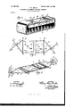
- Figure 1 is a perspective view of a shoe-brush provided with my improved polishing attachment.
- Fig. 2 is a detail plan view of my improved attachment .in detached position, the same being broken away centrally.
- Fig. 3 is a perspective View of a modified form of construction, the same being shown in detached and inverted position and being broken away centrally.
- FIG. 1 designates my improved attachment, which is shown in Fig. 1 as applied to a shoe-brush 2 in position to cover the bristles 3 of the same, in which position it may be effectively employed to polish shoes by operating the brush 2 in the customary manner.
- the bristles 3 furnish a yielding backing for the attachment and enhance the operative effect of the friction 'of the attachment upon the shoes.
- the attachment may be directly connected with any substitute for the brush 2, the brush constituting, however, the preferable means for manipulating or carrying the attachment.
- the attachment 1 consists of a flexible and elongated strip 5 of suitable soft fabric, which strip is provided at its ends with clamping members 6, which in use are connected with the back 7 of the brush 2 to hold the attachment firmlyin position with the flexible strip 5 across and beneath the bristles 3 of the brush.
- the clamping members 6 maintain the strip 5 firmly in position, so that the latter may be rapidly moved across the surface of the shoe to polish the same.
- each of the clamping members 6 consists of two spring-arms 8, each of which arms 8 is provided with an angularly-projecting jaw 9, and the arms 8 are adapted to extend oppositelyacross the back 7 of the brush in position to permit engage- 6o ment of the jaws 9 with the sides 10 of the back 7 of the brush.
- the jaws 9 may be provided each with angularly-projecting pointed ends 11, which are formed to oppositely enter the sides 10 of the back 7 of the brush.
- the spring-arms 8 are connected at their inner ends by a cross-bar 12, and each end of the flexible strip 5 is connected with the crossbar 12 of one of the clamping members 6.
- the spring-arms 8 are slidably connected, as at 13, at the point they cross each other in angular relation.
- the spring-arms 8, jaws 9, and crossbar 12 may be composed of a single length 14 of stiff spring-wire, which length of wire is formed centrally into the cross-bar 12. 7-5
- the length of wire is bent at an angle, as at 15, and is thence extended to form one of the springarms 8.
- the length of wire 14 is angularly bent to form one of the jaws 9 and is again angularly bent at the outer end 'of each jaw 9, as at 17, to form one of the angularly-pointed ends 11.
- the means of slidable connection of the arms 8 as at 13 may consist of a closed loop 18, which is formed in one of the arms 8, and through which loop the other arm 8 may pass. This loop also prevents disconnection of the arms 8 and maintains the same in proper angular relation for ready 9o connection with the back 7 of the brush.
- the clamping members 6 are formed as above described, with the exception that in substitution for the means of slidable connection at 13 means of slidable connection 19 are provided, which consist of a ring 20, which passes about both of the spring-arms Sin a loose-running slidable connection.
- a stop device 21 is carried by one of the spring-arms S to prevent the disengagement or detachment of the ring 20 from the spring-arms 8, and said stop device 21 may consist in a side loop 22, formed in one of the spring-arms 8 adjacent the outer end thereof.
- the flexible strip 5 is applied to the brush across the bristle portion 3 of the same, the end portions of the strip 5 being wrapped around the end portions of the back 7 of the brush, whereby the clamping members 6 may be extended in flat position across the back of the brush to permit engagement of the pointed jaws 9 with the sides 10 of the back of the brush.
- the spring quality of the arms 8, together with the spring quality of the cross-bar 12, maintains the jaws 9 in firm operative engagement with the sides 10 of the back of the brush.
- the jaws 9 are thus secured in position by relatively spreading the same and slipping the same about the sides of the back of the brush.
- the jaws 9 may be readily detached from the back of the brush to permit'of detachment of the entire attachment.
- the operation and use of the modified form of construction shown in Figs. 4 and 5 are the same as that last described.
- An improved polishing attachment for shoe-brushes com prising a flexible bod y-strip adapted to be secured across the bristles of the brush and provided at each end with a clamping member arranged for engagement with the back of the brush, each of said clamping members consisting of a plurality of spring-arms provided with pointed jaws.
- An improved polishing attachment for shoe-brushes comprising a flexible body-strip adapted to be secured across the bristles of the brush and provided at each end with a clamping member arranged for engagement with the back of the brush, each of said clamping members consisting of a plurality of slidably-connected and crossed springarins provided with pointed jaws.
- An improved polishing attachment for shoe-brushes comprising a flexible body-stri p adapted to be secured across the bristles of the brush and provided at each end with a clamping member arranged for engagement with the back of the brush, each of said clamping members consisting of two slidablyconnected and crossed spring-arms provided with pointed jaws, said spring-arms of each clamping member being connected at their inner ends by a cross-bar with which the re spective ends of the bod y-strip are connected.
- a body portion provided with a clamping member consisting of a single length of stiff spring-wire which is formed centrally into a cross-bar, the wire being angularly bent at the ends of the cross-bar to form spring-arms the outer ends of which are formed into pointed jaws, and means for maintaining said spring-arms in slidable connection and crossed relation.
- a body portion provided With a clamping member consisting of a single length of stiff spring-wire which is formed centrally into a crossbar, the wire being angularly bent at the ends of the cross-bar to form spring-arms the outer ends of which are formed into pointed jaws, one of said springarms embodying an integral loop through which the other of said spring-armsis passed and whereby said spring-arms are maintained in s1idably-connected and crossed relation.
- An improved polishing attachment for shoe-brushes comprising a body portion adapted to be secured across the bristles of the brush and provided with means for clamping the same to the brush, said clamping means consisting of spring-arms provided with pointed jaws.
Description
' No. 683,038. Patented Sept. 24', I901.
- T. o. GRILLS.
POLISHING ATTACHMENT FOB SHOE BRUSHES.
(An'plication filed my 4, 1901.)
(No Model.)
% l/VVENTO?| 7H: NORRIS Perms co. wowu'rna, WASNINOYON, 174 c UNITED STATES PATENT OFFICE.
THOMAS OSCAR GRILLS, OF BROOKLYN, NEW YORK.
POLISHING ATTACHMENT FOR SHOE-BRUSHES.
SPEGIFLCATION formingpart of Letters Patent No. 683,038, dated September 24, 1901'.
Application filed May 4, 1901. Serial No. 58.695. (No model.)
" ments for Shoe-Brushes, of which -the follow-- ing is a specification.
This invention relates to polishing attachments for shoe-brushes; and it has for its object to provide an improved device of this class which may be readily connected with and detached from a shoe-brush or other suitable device and which will be simple and inexpensive in construction and durable and generally efficient in use.
In the drawings, Figure 1 is a perspective view of a shoe-brush provided with my improved polishing attachment. Fig. 2 is a detail plan view of my improved attachment .in detached position, the same being broken away centrally. Fig. 3 is a perspective View of a modified form of construction, the same being shown in detached and inverted position and being broken away centrally.
Corresponding parts in all the figures are denoted by the same reference characters.
Referring to the drawings, 1 designates my improved attachment, which is shown in Fig. 1 as applied to a shoe-brush 2 in position to cover the bristles 3 of the same, in which position it may be effectively employed to polish shoes by operating the brush 2 in the customary manner. The bristles 3 furnish a yielding backing for the attachment and enhance the operative effect of the friction 'of the attachment upon the shoes. It will be understood that the attachment may be directly connected with any substitute for the brush 2, the brush constituting, however, the preferable means for manipulating or carrying the attachment.
In the preferred form of construction the attachment 1 consists of a flexible and elongated strip 5 of suitable soft fabric, which strip is provided at its ends with clamping members 6, which in use are connected with the back 7 of the brush 2 to hold the attachment firmlyin position with the flexible strip 5 across and beneath the bristles 3 of the brush. The clamping members 6 maintain the strip 5 firmly in position, so that the latter may be rapidly moved across the surface of the shoe to polish the same. In the preferred form of construction each of the clamping members 6 consists of two spring-arms 8, each of which arms 8 is provided with an angularly-projecting jaw 9, and the arms 8 are adapted to extend oppositelyacross the back 7 of the brush in position to permit engage- 6o ment of the jaws 9 with the sides 10 of the back 7 of the brush. The jaws 9 may be provided each with angularly-projecting pointed ends 11, which are formed to oppositely enter the sides 10 of the back 7 of the brush. The spring-arms 8 are connected at their inner ends by a cross-bar 12, and each end of the flexible strip 5 is connected with the crossbar 12 of one of the clamping members 6. The spring-arms 8 are slidably connected, as at 13, at the point they cross each other in angular relation. The spring-arms 8, jaws 9, and crossbar 12 may be composed of a single length 14 of stiff spring-wire, which length of wire is formed centrally into the cross-bar 12. 7-5 At each end of the cross-bar 12 the length of wire is bent at an angle, as at 15, and is thence extended to form one of the springarms 8. At the outer end of each of the springarms 8, as at 16, the length of wire 14 is angularly bent to form one of the jaws 9 and is again angularly bent at the outer end 'of each jaw 9, as at 17, to form one of the angularly-pointed ends 11. The means of slidable connection of the arms 8 as at 13 may consist of a closed loop 18, which is formed in one of the arms 8, and through which loop the other arm 8 may pass. This loop also prevents disconnection of the arms 8 and maintains the same in proper angular relation for ready 9o connection with the back 7 of the brush.
In the modified form of construction shown in Figs. 4 and 5 the clamping members 6 are formed as above described, with the exception that in substitution for the means of slidable connection at 13 means of slidable connection 19 are provided, which consist of a ring 20, which passes about both of the spring-arms Sin a loose-running slidable connection. A stop device 21 is carried by one of the spring-arms S to prevent the disengagement or detachment of the ring 20 from the spring-arms 8, and said stop device 21 may consist in a side loop 22, formed in one of the spring-arms 8 adjacent the outer end thereof.
The operation and advantages of my improved polishing attachment for shoe-brushes will be readily understood. The flexible strip 5 is applied to the brush across the bristle portion 3 of the same, the end portions of the strip 5 being wrapped around the end portions of the back 7 of the brush, whereby the clamping members 6 may be extended in flat position across the back of the brush to permit engagement of the pointed jaws 9 with the sides 10 of the back of the brush. The spring quality of the arms 8, together with the spring quality of the cross-bar 12, maintains the jaws 9 in firm operative engagement with the sides 10 of the back of the brush. The jaws 9 are thus secured in position by relatively spreading the same and slipping the same about the sides of the back of the brush. By the reverse operation the jaws 9 may be readily detached from the back of the brush to permit'of detachment of the entire attachment. The operation and use of the modified form of construction shown in Figs. 4 and 5 are the same as that last described.
I do not desire to be understood as limiting myself to the details of construction and arrangement as herein described and illustrated, as it is manifest that variations and modifications may be made'in the features of construction and arrangement in the adaptation of the device to various conditions of use without departing from the spirit and scope of my invention and improvements. I therefore reserve the right to all such variations and modifications as properly fall with- .in the scope of my invention and the terms of the following claims.
Having thus described my invention, 1 claim and desire to secure by Letters Patent 1. An improved polishing attachment for shoe-brushes, com prising a flexible bod y-strip adapted to be secured across the bristles of the brush and provided at each end with a clamping member arranged for engagement with the back of the brush, each of said clamping members consisting of a plurality of spring-arms provided with pointed jaws.
2. An improved polishing attachment for shoe-brushes, comprising a flexible body-strip adapted to be secured across the bristles of the brush and provided at each end with a clamping member arranged for engagement with the back of the brush, each of said clamping members consisting of a plurality of slidably-connected and crossed springarins provided with pointed jaws.
3. An improved polishing attachment for shoe-brushes, comprising a flexible body-stri p adapted to be secured across the bristles of the brush and provided at each end with a clamping member arranged for engagement with the back of the brush, each of said clamping members consisting of two slidablyconnected and crossed spring-arms provided with pointed jaws, said spring-arms of each clamping member being connected at their inner ends by a cross-bar with which the re spective ends of the bod y-strip are connected.
4. In an improved polishing attachment of the class described, a body portion provided with a clamping member consisting of a single length of stiff spring-wire which is formed centrally into a cross-bar, the wire being angularly bent at the ends of the cross-bar to form spring-arms the outer ends of which are formed into pointed jaws, and means for maintaining said spring-arms in slidable connection and crossed relation.
5. In an improved polishing atttachment of the class described, a body portion provided With a clamping member consisting of a single length of stiff spring-wire which is formed centrally into a crossbar, the wire being angularly bent at the ends of the cross-bar to form spring-arms the outer ends of which are formed into pointed jaws, one of said springarms embodying an integral loop through which the other of said spring-armsis passed and whereby said spring-arms are maintained in s1idably-connected and crossed relation.
6. An improved polishing attachment for shoe-brushes, comprising a body portion adapted to be secured across the bristles of the brush and provided with means for clamping the same to the brush, said clamping means consisting of spring-arms provided with pointed jaws.
In testimony whereof I have signed my name in the presence of the subscribing witnesses.
THOMAS OSCAR GRILLS.
Witnesses:
V J. R. LITTELL,
GEO. VAIL HUPPERTZ.
ICO
Priority Applications (1)
| Application Number | Priority Date | Filing Date | Title |
|---|---|---|---|
| US5869501A US683038A (en) | 1901-05-04 | 1901-05-04 | Polishing attachment for shoe-brushes. |
Applications Claiming Priority (1)
| Application Number | Priority Date | Filing Date | Title |
|---|---|---|---|
| US5869501A US683038A (en) | 1901-05-04 | 1901-05-04 | Polishing attachment for shoe-brushes. |
Publications (1)
| Publication Number | Publication Date |
|---|---|
| US683038A true US683038A (en) | 1901-09-24 |
Family
ID=2751581
Family Applications (1)
| Application Number | Title | Priority Date | Filing Date |
|---|---|---|---|
| US5869501A Expired - Lifetime US683038A (en) | 1901-05-04 | 1901-05-04 | Polishing attachment for shoe-brushes. |
Country Status (1)
| Country | Link |
|---|---|
| US (1) | US683038A (en) |
-
1901
- 1901-05-04 US US5869501A patent/US683038A/en not_active Expired - Lifetime
Similar Documents
| Publication | Publication Date | Title |
|---|---|---|
| US719650A (en) | Holder for sleeve-protectors. | |
| US729338A (en) | Holder for brushes. | |
| US683038A (en) | Polishing attachment for shoe-brushes. | |
| US683750A (en) | Fish-hook. | |
| US734954A (en) | Sandpaper-holder. | |
| US20220386825A1 (en) | Personal Hygiene Device | |
| US1006367A (en) | Fish-grip. | |
| US589550A (en) | Dusting-brush | |
| US725462A (en) | Silk-holder. | |
| US648794A (en) | Fly-killer brush. | |
| US398173A (en) | George e | |
| US457797A (en) | Handle-extension | |
| US1135745A (en) | Hair-holder. | |
| US1077345A (en) | Barrette. | |
| US295685A (en) | Broom-band | |
| US355873A (en) | Thomas humphrey | |
| US786280A (en) | Shoe-polisher. | |
| US1296258A (en) | Cow-tail holder. | |
| US547320A (en) | Broom-bridle for attaching cloths for brushing purposes | |
| US431487A (en) | James m | |
| US751036A (en) | Shoe-shining frame | |
| US1053839A (en) | Nail-buffer. | |
| US1232065A (en) | Shoe-polishing device. | |
| US1052043A (en) | Dentifrice-applicator. | |
| US1175510A (en) | Mop. |