US6829805B2 - Locking device for exhaust filter of vacuum cleaner - Google Patents
Locking device for exhaust filter of vacuum cleaner Download PDFInfo
- Publication number
- US6829805B2 US6829805B2 US10/150,980 US15098002A US6829805B2 US 6829805 B2 US6829805 B2 US 6829805B2 US 15098002 A US15098002 A US 15098002A US 6829805 B2 US6829805 B2 US 6829805B2
- Authority
- US
- United States
- Prior art keywords
- filter
- vacuum cleaner
- exhaust
- exhaust filter
- mounting grooves
- Prior art date
- Legal status (The legal status is an assumption and is not a legal conclusion. Google has not performed a legal analysis and makes no representation as to the accuracy of the status listed.)
- Expired - Fee Related, expires
Links
Images


Classifications
-
- A—HUMAN NECESSITIES
- A47—FURNITURE; DOMESTIC ARTICLES OR APPLIANCES; COFFEE MILLS; SPICE MILLS; SUCTION CLEANERS IN GENERAL
- A47L—DOMESTIC WASHING OR CLEANING; SUCTION CLEANERS IN GENERAL
- A47L9/00—Details or accessories of suction cleaners, e.g. mechanical means for controlling the suction or for effecting pulsating action; Storing devices specially adapted to suction cleaners or parts thereof; Carrying-vehicles specially adapted for suction cleaners
- A47L9/10—Filters; Dust separators; Dust removal; Automatic exchange of filters
- A47L9/12—Dry filters
- A47L9/127—Dry filters tube- or sleeve-shaped
-
- A—HUMAN NECESSITIES
- A47—FURNITURE; DOMESTIC ARTICLES OR APPLIANCES; COFFEE MILLS; SPICE MILLS; SUCTION CLEANERS IN GENERAL
- A47L—DOMESTIC WASHING OR CLEANING; SUCTION CLEANERS IN GENERAL
- A47L9/00—Details or accessories of suction cleaners, e.g. mechanical means for controlling the suction or for effecting pulsating action; Storing devices specially adapted to suction cleaners or parts thereof; Carrying-vehicles specially adapted for suction cleaners
- A47L9/0081—Means for exhaust-air diffusion; Means for sound or vibration damping
-
- Y—GENERAL TAGGING OF NEW TECHNOLOGICAL DEVELOPMENTS; GENERAL TAGGING OF CROSS-SECTIONAL TECHNOLOGIES SPANNING OVER SEVERAL SECTIONS OF THE IPC; TECHNICAL SUBJECTS COVERED BY FORMER USPC CROSS-REFERENCE ART COLLECTIONS [XRACs] AND DIGESTS
- Y10—TECHNICAL SUBJECTS COVERED BY FORMER USPC
- Y10S—TECHNICAL SUBJECTS COVERED BY FORMER USPC CROSS-REFERENCE ART COLLECTIONS [XRACs] AND DIGESTS
- Y10S55/00—Gas separation
- Y10S55/03—Vacuum cleaner
Definitions
- the present invention relates to a vacuum cleaner, and more particularly, to a locking device for an exhaust filter of a vacuum cleaner, which can securely lock the exhaust filter installed on an outer surface of the vacuum cleaner.
- a main body 2 of a vacuum cleaner is formed on both side surfaces thereof with exhaust portions 4 through which air is exhausted.
- the exhaust portions serve to discharge, to the exterior of the vacuum cleaner, air resulting from removal of foreign substances from air containing the foreign substances introduced into the main body of the vacuum cleaner.
- the exhaust portions 4 are formed by attaching both filters 4 b and exhaust filter covers 4 a to exhaust holes 6 a formed on both side surfaces of a casing of the main body of the vacuum cleaner, which includes an upper casing 6 and a lower casing 8 , as shown in FIG. 2 .
- Each exhaust filter cover 4 a is fixed to the casing of the main body by fitting a protrusion 4 c formed on an outer peripheral surface of the exhaust filter cover into the casing of the main body in which the exhaust holes 6 a are formed.
- each filter 4 b serves to finally filter out the foreign substances, which may be contained in the exhausted air.
- the filter 4 b is positioned between the exhaust filter cover 4 a and the exhaust hole 6 a.
- vibration and noise are generated due to driving of a motor contained within the main body upon operation of the vacuum cleaner.
- the vibration generated as such is transferred to both the exhaust filter cover 4 a and the filter 4 b .
- the filter 4 b since the filter 4 b is supported in a state where it is simply inserted between the exhaust filter cover 4 a and the main body of the vacuum cleaner without an additional support relationship, the filter 4 b is rattled by such vibration. Accordingly, there are probabilities that the filter 4 b will come into contact with the cover 4 a or the main body of the vacuum cleaner in the vicinity of the filter, and any undesired contact noise will be generated due to such contact.
- An object of the present invention is to provide a locking device for an exhaust filter of a vacuum cleaner, which can perfectly prevent noise generation in the vicinity of the exhaust filter upon operation of the vacuum cleaner by more securely locking the exhaust filter.
- a locking device for an exhaust filter of a vacuum cleaner comprising an exhaust filter cover mounted on one side surface of a main body of the vacuum cleaner, and including a plurality of exhaust holes and a plurality of mounting grooves formed on an inner surface of a cylindrical sidewall of the exhaust filter cover; and a filter including a filtering portion for filtering air, and engagement protrusions formed on a cylindrical outer peripheral surface of the filter to be resiliently locked within the mounting grooves, respectively, whereby the filter is resiliently locked within the exhaust filter cover.
- the mounting grooves take a -shape, or bayonet-shape, and the engagement protrusions are inserted into the respective mounting grooves and then rotated in a predetermined direction to be locked within the mounting grooves, respectively.
- engagement protrusions are formed just in front of trail ends of the -shaped or bayonet-shaped, mounting grooves so as to maintain a state where the engagement protrusions have entered the trail ends of the mounting grooves, respectively.
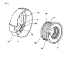
- FIG. 3 is an exploded perspective view showing the constitution of an exhaust filter according to the present invention.
- the mounting ring 14 includes a sidewall 15 which can come into close contact with an outer peripheral surface 22 of a filter 20 .
- the outer peripheral surface 22 of the filter 20 is formed to be approximately perpendicular to the substantially vertical side surface of the main body of the vacuum cleaner. Accordingly, the sidewall 15 of the mounting ring 14 of the exhaust filter cover 10 is also formed to be substantially perpendicular to the side surface of the main body of the vacuum cleaner.
- Mounting grooves 16 are formed on an inner surface of the sidewall 15 . As shown in the figure, the respective mounting grooves 16 take a -shape, or bayonet-shape, and engagement projections 16 a protruding into the grooves are formed just in front of trail ends of the mounting grooves 16 , respectively.
- the filter 20 includes a filtering portion 24 and a support frame portion 21 for supporting the filtering portion, and the support frame portion 21 defines right and left ends of the filter.
- a left (outer) frame portion of the cylindrical filter 20 defines the outer peripheral surface 22 , and the outer peripheral surface 22 is formed with a plurality of engagement protrusions 26 .
- the engagement protrusions 26 are formed on the outer peripheral surface 22 of the filter 20 , and that the filter 20 is securely locked within the mounting ring 14 of the exhaust filter cover 10 by these engagement protrusions.
- various changes may be made to the configuration of the mounting grooves 16 within which the engagement protrusions 26 are locked. That is, various changes may be made to the mounting grooves 16 according to the present invention as far as the filter 20 does not accidentally escape from the exhaust filter cover by engagement of the engagement protrusions 26 with the mounting grooves.
- locking grooves within which the engagement protrusions 26 can be resiliently locked may be formed on the inner surface of the sidewall 15 of the mounting ring 14 , so that the filter 20 can be securely locked within the exhaust filter cover 10 .
- the exhaust filter cover 10 can be mounted on the side surface of the main body of the vacuum cleaner in a state where the filter 20 is perfectly mounted on the exhaust filter cover 10 . Therefore, it can be expected to obtain an advantage in that noise due to contact of the filter 20 with the other parts is not generated since the filter 20 can be securely supported even against external vibration and can be not rattled by any vibration generated during operation of the vacuum cleaner.
Abstract
The present invention relates to a locking device for mounting an exhaust filter of a vacuum cleaner on an exhaust filter cover. According to the present invention, there is provided a locking device for an exhaust filter of a vacuum cleaner, comprising a locking device for an exhaust filter of a vacuum cleaner, comprising an exhaust filter cover mounted on one side surface of a main body of the vacuum cleaner, and including a plurality of exhaust holes and a plurality of mounting grooves formed on an inner surface of a cylindrical sidewall of the exhaust filter cover; and a filter including a filtering portion for filtering air, and engagement protrusions formed on a cylindrical outer peripheral surface of the filter to be resiliently locked within the mounting grooves, respectively, whereby the filter is resiliently locked within the exhaust filter cover. Therefore, the filter is not rattled by any vibration, and no contact noise is generated.
Description
1. Field of the Invention
The present invention relates to a vacuum cleaner, and more particularly, to a locking device for an exhaust filter of a vacuum cleaner, which can securely lock the exhaust filter installed on an outer surface of the vacuum cleaner.
2. Description of the Prior Art
As shown in FIG. 1, a main body 2 of a vacuum cleaner is formed on both side surfaces thereof with exhaust portions 4 through which air is exhausted. The exhaust portions serve to discharge, to the exterior of the vacuum cleaner, air resulting from removal of foreign substances from air containing the foreign substances introduced into the main body of the vacuum cleaner.
The exhaust portions 4 are formed by attaching both filters 4 b and exhaust filter covers 4 a to exhaust holes 6 a formed on both side surfaces of a casing of the main body of the vacuum cleaner, which includes an upper casing 6 and a lower casing 8, as shown in FIG. 2.
Each exhaust filter cover 4 a is fixed to the casing of the main body by fitting a protrusion 4 c formed on an outer peripheral surface of the exhaust filter cover into the casing of the main body in which the exhaust holes 6 a are formed. Here, each filter 4 b serves to finally filter out the foreign substances, which may be contained in the exhausted air. The filter 4 b is positioned between the exhaust filter cover 4 a and the exhaust hole 6 a.
In general, vibration and noise are generated due to driving of a motor contained within the main body upon operation of the vacuum cleaner. The vibration generated as such is transferred to both the exhaust filter cover 4 a and the filter 4 b. According to the conventional constitution, since the filter 4 b is supported in a state where it is simply inserted between the exhaust filter cover 4 a and the main body of the vacuum cleaner without an additional support relationship, the filter 4 b is rattled by such vibration. Accordingly, there are probabilities that the filter 4 b will come into contact with the cover 4 a or the main body of the vacuum cleaner in the vicinity of the filter, and any undesired contact noise will be generated due to such contact.
The present invention is contemplated to solve the above problems in the prior art. An object of the present invention is to provide a locking device for an exhaust filter of a vacuum cleaner, which can perfectly prevent noise generation in the vicinity of the exhaust filter upon operation of the vacuum cleaner by more securely locking the exhaust filter.
According to the present invention for accomplishing the above object, there is provided a locking device for an exhaust filter of a vacuum cleaner, comprising an exhaust filter cover mounted on one side surface of a main body of the vacuum cleaner, and including a plurality of exhaust holes and a plurality of mounting grooves formed on an inner surface of a cylindrical sidewall of the exhaust filter cover; and a filter including a filtering portion for filtering air, and engagement protrusions formed on a cylindrical outer peripheral surface of the filter to be resiliently locked within the mounting grooves, respectively, whereby the filter is resiliently locked within the exhaust filter cover.
According to one embodiment of the present invention, the mounting grooves take a -shape, or bayonet-shape, and the engagement protrusions are inserted into the respective mounting grooves and then rotated in a predetermined direction to be locked within the mounting grooves, respectively.
According to another embodiment of the present invention, engagement protrusions are formed just in front of trail ends of the -shaped or bayonet-shaped, mounting grooves so as to maintain a state where the engagement protrusions have entered the trail ends of the mounting grooves, respectively.
The above and other objects and features of the present invention will become apparent from the following description of a preferred embodiment given in conjunction with the accompanying drawings, in which:
FIG. 1 is a perspective view of a main body of a conventional vacuum cleaner;
FIG. 2 is an exploded perspective view of the conventional vacuum cleaner, showing the constitution of portions in the vicinity of a conventional exhaust filter thereof; and
FIG. 3 is an exploded perspective view showing the constitution of an exhaust filter according to the present invention.
Hereinafter, a preferred embodiment of the present invention will be described in detail with reference to the accompanying drawings.
As shown in FIG. 3, an exhaust filter cover 10 according to the present invention, which is attached to one side surface of a main body of a vacuum cleaner, is formed with a plurality of exhaust holes 12 through which air is exhausted. In one embodiment, the exhaust filter cover 10 is formed with a circular mounting ring 14 at the center thereof, and the exhaust holes 12 are formed radially outside of a perimeter of the mounting ring 14.
The mounting ring 14 includes a sidewall 15 which can come into close contact with an outer peripheral surface 22 of a filter 20. The outer peripheral surface 22 of the filter 20 is formed to be approximately perpendicular to the substantially vertical side surface of the main body of the vacuum cleaner. Accordingly, the sidewall 15 of the mounting ring 14 of the exhaust filter cover 10 is also formed to be substantially perpendicular to the side surface of the main body of the vacuum cleaner.
Next, the cylindrical filter 20 according to the present invention will be described in detail. The filter 20 includes a filtering portion 24 and a support frame portion 21 for supporting the filtering portion, and the support frame portion 21 defines right and left ends of the filter. A left (outer) frame portion of the cylindrical filter 20 defines the outer peripheral surface 22, and the outer peripheral surface 22 is formed with a plurality of engagement protrusions 26.
Next, the engagement relationship between the filter 20 and the exhaust filter cover 10 will be described in detail. The cylindrical outer peripheral surface 22 of the filter 20 is fitted into the mounting ring 14 of the exhaust filter cover 10. At this time, the outer peripheral surface 22 comes into close contact with the sidewall 15 of the mounting ring 14, and the engagement protrusions 26 formed protrudingly from the outer peripheral surface 22 enter the mounting grooves 16, respectively. In a state where the engagement protrusions 26 have entered the mounting grooves 16 by a predetermined distance, respectively, the filter 20 is rotated in the counterclockwise direction designated by an arrow so that the engagement protrusions 26 can be engaged with the trail ends of the -shaped or bayonet-shaped, mounting grooves 16, respectively.
When the engagement protrusions 26 are perfectly engaged with the trail ends, the engagement protrusions 26 are in a state where they are reach the trail ends beyond the engagement projections 16 a to be resiliently locked by the engagement projections 16 a, respectively.
According to the present invention, it is a basic technical spirit of the present invention that the engagement protrusions 26 are formed on the outer peripheral surface 22 of the filter 20, and that the filter 20 is securely locked within the mounting ring 14 of the exhaust filter cover 10 by these engagement protrusions.
Within the scope of the basic technical spirit of the present invention, it can be understood by the skilled in the art that various changes and modifications can be made to the present invention.
For example, various changes may be made to the configuration of the mounting grooves 16 within which the engagement protrusions 26 are locked. That is, various changes may be made to the mounting grooves 16 according to the present invention as far as the filter 20 does not accidentally escape from the exhaust filter cover by engagement of the engagement protrusions 26 with the mounting grooves. For example, locking grooves within which the engagement protrusions 26 can be resiliently locked may be formed on the inner surface of the sidewall 15 of the mounting ring 14, so that the filter 20 can be securely locked within the exhaust filter cover 10.
According to the present invention as described above, the exhaust filter cover 10 can be mounted on the side surface of the main body of the vacuum cleaner in a state where the filter 20 is perfectly mounted on the exhaust filter cover 10. Therefore, it can be expected to obtain an advantage in that noise due to contact of the filter 20 with the other parts is not generated since the filter 20 can be securely supported even against external vibration and can be not rattled by any vibration generated during operation of the vacuum cleaner.
Claims (3)
1. A locking device for an exhaust filter of a vacuum cleaner, comprising:
an exhaust filter cover mounted on one side surface of a main body of the vacuum cleaner, and including a plurality of exhaust holes and a plurality of mounting grooves formed on an inner surface of a cylindrical sidewall of the exhaust filter cover; and
a filter including a filtering portion for filtering air, and engagement protrusions formed on a cylindrical outer peripheral surface of the filter to be resiliently locked within the mounting grooves, respectively,
whereby the filter is resiliently locked within the exhaust filter cover.
2. The locking device as claimed in claim 1 , wherein the mounting grooves take a bayonet-shape, and the engagement protrusions are inserted into the respective mounting grooves and then rotated in a predetermined direction to be locked within the respective mounting grooves.
3. The locking device as claimed in claim 2 , wherein engagement projections are formed just in front of trail ends of the bayonet-shaped mounting grooves so as to maintain a state where the engagement protrusions have entered the trail ends of the mounting grooves, respectively.
Applications Claiming Priority (2)
| Application Number | Priority Date | Filing Date | Title |
|---|---|---|---|
| KR2001-82129 | 2001-12-20 | ||
| KR10-2001-0082129A KR100424581B1 (en) | 2001-12-20 | 2001-12-20 | Device for locking ventilation filter for vacuum cleaner |
Publications (2)
| Publication Number | Publication Date |
|---|---|
| US20030115713A1 US20030115713A1 (en) | 2003-06-26 |
| US6829805B2 true US6829805B2 (en) | 2004-12-14 |
Family
ID=19717354
Family Applications (1)
| Application Number | Title | Priority Date | Filing Date |
|---|---|---|---|
| US10/150,980 Expired - Fee Related US6829805B2 (en) | 2001-12-20 | 2002-05-21 | Locking device for exhaust filter of vacuum cleaner |
Country Status (8)
| Country | Link |
|---|---|
| US (1) | US6829805B2 (en) |
| EP (1) | EP1321088B1 (en) |
| JP (1) | JP3571707B2 (en) |
| KR (1) | KR100424581B1 (en) |
| CN (1) | CN1426741A (en) |
| AU (1) | AU777604B2 (en) |
| DE (1) | DE60233027D1 (en) |
| RU (1) | RU2234231C2 (en) |
Cited By (18)
| Publication number | Priority date | Publication date | Assignee | Title |
|---|---|---|---|---|
| US20100229323A1 (en) * | 2009-03-11 | 2010-09-16 | G.B.D. Corp. | Portable surface cleaning apparatus |
| EP2229860A2 (en) | 2009-03-20 | 2010-09-22 | Bissell Homecare, Inc. | Filter locking arrangement for a vacuum cleaner |
| US20100236014A1 (en) * | 2009-03-19 | 2010-09-23 | Bissell Homecare, Inc. | Vacuum Cleaner and Filters Therefor |
| US20120024620A1 (en) * | 2010-07-29 | 2012-02-02 | Parlux S.P.A. | Silencer device for a hair dryer |
| US20120222261A1 (en) * | 2011-03-03 | 2012-09-06 | Hilti Aktiengesellschaft | Vacuum cleaner |
| US9801514B2 (en) | 2013-04-22 | 2017-10-31 | Techtronic Industries Co. Ltd. | Vacuum cleaner filter housing |
| US20170332864A1 (en) * | 2016-05-20 | 2017-11-23 | Lg Electronics Inc. | Autonomous cleaner |
| US10342405B2 (en) | 2016-05-20 | 2019-07-09 | Lg Electronics Inc. | Autonomous cleaner |
| US10342400B2 (en) | 2016-05-20 | 2019-07-09 | Lg Electronics Inc. | Autonomous cleaner |
| US10362916B2 (en) | 2016-05-20 | 2019-07-30 | Lg Electronics Inc. | Autonomous cleaner |
| US10368706B1 (en) | 2018-07-17 | 2019-08-06 | Shop Vac Corporation | Vacuum filter having annular catch |
| US10398276B2 (en) | 2016-05-20 | 2019-09-03 | Lg Electronics Inc. | Autonomous cleaner |
| US10420448B2 (en) | 2016-05-20 | 2019-09-24 | Lg Electronics Inc. | Autonomous cleaner |
| US10463221B2 (en) | 2016-05-20 | 2019-11-05 | Lg Electronics Inc. | Autonomous cleaner |
| US10463212B2 (en) | 2016-05-20 | 2019-11-05 | Lg Electronics Inc. | Autonomous cleaner |
| US10481611B2 (en) | 2016-05-20 | 2019-11-19 | Lg Electronics Inc. | Autonomous cleaner |
| US10524628B2 (en) | 2016-05-20 | 2020-01-07 | Lg Electronics Inc. | Autonomous cleaner |
| US11846937B2 (en) | 2016-05-20 | 2023-12-19 | Lg Electronics Inc. | Autonomous cleaner |
Families Citing this family (9)
| Publication number | Priority date | Publication date | Assignee | Title |
|---|---|---|---|---|
| CN100382736C (en) * | 2003-09-27 | 2008-04-23 | 乐金电子(天津)电器有限公司 | Structure of exhaust gas filter unit of vacuum cleaner |
| GB0402847D0 (en) * | 2004-02-10 | 2004-03-17 | Black & Decker Inc | Filter assembly for vacuum cleaner and vacuum cleaner incorporating such assembly |
| KR20100093447A (en) * | 2009-02-16 | 2010-08-25 | 삼성광주전자 주식회사 | Dust collector for vacuum cleaner |
| USD806336S1 (en) * | 2015-05-15 | 2017-12-26 | Sharkninja Operating Llc | Caddy for a cleaning appliance |
| CN105673631A (en) * | 2016-03-23 | 2016-06-15 | 深圳市创客星空科技有限公司 | Rotary screw and rotary nut fastener structure |
| US11166607B2 (en) | 2016-03-31 | 2021-11-09 | Lg Electronics Inc. | Cleaner |
| AU2017240615B2 (en) | 2016-03-31 | 2019-12-05 | Lg Electronics Inc. | Cleaning apparatus |
| KR20210067638A (en) * | 2019-11-29 | 2021-06-08 | 엘지전자 주식회사 | Cleaner |
| DE102020128176A1 (en) | 2020-10-27 | 2022-04-28 | Alfred Kärcher SE & Co. KG | Cartridge filter for a teat and teat |
Citations (9)
| Publication number | Priority date | Publication date | Assignee | Title |
|---|---|---|---|---|
| US3841067A (en) * | 1972-09-05 | 1974-10-15 | Mitsubishi Electric Corp | Electric vacuum cleaner |
| US4577365A (en) * | 1983-09-14 | 1986-03-25 | John Manufacturing Limited | Rechargeable vacuum cleaner |
| US5074006A (en) * | 1989-09-01 | 1991-12-24 | Nunzio Eremita | Pet vacuum comb |
| US5810911A (en) * | 1996-09-05 | 1998-09-22 | Braun Aktiengesellschaft | Filter device for an air-moving hair care appliance |
| US5946771A (en) * | 1997-01-09 | 1999-09-07 | The Hoover Company | Vacuum cleaner air exhaust arrangement |
| US6341404B1 (en) * | 2000-01-13 | 2002-01-29 | Royal Appliance Mfg. Co. | Upright vacuum cleaner with cyclonic airflow pathway |
| US20020162188A1 (en) * | 2001-05-02 | 2002-11-07 | Harmen John T. | Vacuum cleaner |
| US20020166200A1 (en) * | 1999-01-08 | 2002-11-14 | Conrad Wayne Ernest | Air flow passage for a cyclonic separator and vacuum cleaner having same |
| US6540804B1 (en) * | 1998-11-23 | 2003-04-01 | Blue Air Ab | Air cleaner |
Family Cites Families (14)
| Publication number | Priority date | Publication date | Assignee | Title |
|---|---|---|---|---|
| GB191220176A (en) * | 1912-09-04 | 1912-10-24 | Peder Anderson Fisker | Improvements in and relating to Filters for Vacuum Cleaners and the like. |
| DE3009365A1 (en) * | 1980-03-12 | 1981-09-24 | Rudolf Ing.(grad.) 7530 Pforzheim Mürle | Vacuum cleaner with post filtering - formed as membrane preventing bacteria from re-entering cleaned room |
| KR890002198Y1 (en) * | 1985-12-11 | 1989-04-15 | 김영완 | Water-cleaning device |
| KR200157906Y1 (en) * | 1994-12-24 | 1999-10-01 | 전주범 | The vacuum cleaner |
| US5685894A (en) * | 1995-09-13 | 1997-11-11 | Electrolux Corporation | Filter and accessory mount for upright vacuum cleaner exhaust port |
| US6219880B1 (en) * | 1998-09-17 | 2001-04-24 | Pullman-Holt Corporation | Vacuum cleaner |
| KR200211751Y1 (en) * | 1998-12-31 | 2001-02-01 | 송영소 | Dust collection tester for vacuum cleaner |
| CN1157146C (en) * | 1999-09-16 | 2004-07-14 | Lg电子株式会社 | Device for exhausting in vacuum cleaner |
| KR200176467Y1 (en) * | 1999-10-15 | 2000-04-15 | 주식회사코네트인더스트리 | Motor brush dust filter of cleaner |
| US6402798B1 (en) * | 2000-09-19 | 2002-06-11 | Nelson Industries, Inc. | Twist and lock filter housing with nontorsional anti-rotation stop |
| KR200221892Y1 (en) * | 2000-11-02 | 2001-04-16 | 주식회사안전 | Manhole |
| KR100583566B1 (en) * | 2000-11-17 | 2006-05-26 | 엘지전자 주식회사 | Filter of fixing device for vacuum cleaner |
| KR100582054B1 (en) * | 2000-12-23 | 2006-05-23 | 엘지전자 주식회사 | Filter of fixing device for vacuum cleaner |
| KR100767662B1 (en) * | 2001-03-10 | 2007-10-17 | 엘지전자 주식회사 | Filter Installation Structure for Dust Collector used Cyclone |
-
2001
- 2001-12-20 KR KR10-2001-0082129A patent/KR100424581B1/en not_active IP Right Cessation
-
2002
- 2002-05-17 JP JP2002142827A patent/JP3571707B2/en not_active Expired - Fee Related
- 2002-05-21 US US10/150,980 patent/US6829805B2/en not_active Expired - Fee Related
- 2002-05-22 DE DE60233027T patent/DE60233027D1/en not_active Expired - Fee Related
- 2002-05-22 RU RU2002113401/12A patent/RU2234231C2/en not_active IP Right Cessation
- 2002-05-22 AU AU42441/02A patent/AU777604B2/en not_active Ceased
- 2002-05-22 EP EP02011292A patent/EP1321088B1/en not_active Expired - Lifetime
- 2002-05-23 CN CN02120610A patent/CN1426741A/en active Pending
Patent Citations (9)
| Publication number | Priority date | Publication date | Assignee | Title |
|---|---|---|---|---|
| US3841067A (en) * | 1972-09-05 | 1974-10-15 | Mitsubishi Electric Corp | Electric vacuum cleaner |
| US4577365A (en) * | 1983-09-14 | 1986-03-25 | John Manufacturing Limited | Rechargeable vacuum cleaner |
| US5074006A (en) * | 1989-09-01 | 1991-12-24 | Nunzio Eremita | Pet vacuum comb |
| US5810911A (en) * | 1996-09-05 | 1998-09-22 | Braun Aktiengesellschaft | Filter device for an air-moving hair care appliance |
| US5946771A (en) * | 1997-01-09 | 1999-09-07 | The Hoover Company | Vacuum cleaner air exhaust arrangement |
| US6540804B1 (en) * | 1998-11-23 | 2003-04-01 | Blue Air Ab | Air cleaner |
| US20020166200A1 (en) * | 1999-01-08 | 2002-11-14 | Conrad Wayne Ernest | Air flow passage for a cyclonic separator and vacuum cleaner having same |
| US6341404B1 (en) * | 2000-01-13 | 2002-01-29 | Royal Appliance Mfg. Co. | Upright vacuum cleaner with cyclonic airflow pathway |
| US20020162188A1 (en) * | 2001-05-02 | 2002-11-07 | Harmen John T. | Vacuum cleaner |
Cited By (31)
| Publication number | Priority date | Publication date | Assignee | Title |
|---|---|---|---|---|
| US20100229323A1 (en) * | 2009-03-11 | 2010-09-16 | G.B.D. Corp. | Portable surface cleaning apparatus |
| US20100236014A1 (en) * | 2009-03-19 | 2010-09-23 | Bissell Homecare, Inc. | Vacuum Cleaner and Filters Therefor |
| US8424153B2 (en) * | 2009-03-19 | 2013-04-23 | Bissell Homecare, Inc. | Vacuum cleaner and filters therefor |
| EP2229860A2 (en) | 2009-03-20 | 2010-09-22 | Bissell Homecare, Inc. | Filter locking arrangement for a vacuum cleaner |
| US20100236016A1 (en) * | 2009-03-20 | 2010-09-23 | Bissell Homecare, Inc. | Filter locking arrangement for a vacuum cleaner |
| US8495788B2 (en) | 2009-03-20 | 2013-07-30 | Bissell Homecare, Inc. | Filter locking arrangement for a vacuum cleaner |
| US20120024620A1 (en) * | 2010-07-29 | 2012-02-02 | Parlux S.P.A. | Silencer device for a hair dryer |
| US8307948B2 (en) * | 2010-07-29 | 2012-11-13 | Parlux S.P.A. | Silencer device for a hair dryer |
| US20120222261A1 (en) * | 2011-03-03 | 2012-09-06 | Hilti Aktiengesellschaft | Vacuum cleaner |
| US8813307B2 (en) * | 2011-03-31 | 2014-08-26 | Hilti Aktiengesellschaft | Vacuum cleaner |
| US9801514B2 (en) | 2013-04-22 | 2017-10-31 | Techtronic Industries Co. Ltd. | Vacuum cleaner filter housing |
| US10362916B2 (en) | 2016-05-20 | 2019-07-30 | Lg Electronics Inc. | Autonomous cleaner |
| US10463212B2 (en) | 2016-05-20 | 2019-11-05 | Lg Electronics Inc. | Autonomous cleaner |
| US10342400B2 (en) | 2016-05-20 | 2019-07-09 | Lg Electronics Inc. | Autonomous cleaner |
| US20170332864A1 (en) * | 2016-05-20 | 2017-11-23 | Lg Electronics Inc. | Autonomous cleaner |
| US11846937B2 (en) | 2016-05-20 | 2023-12-19 | Lg Electronics Inc. | Autonomous cleaner |
| US10398276B2 (en) | 2016-05-20 | 2019-09-03 | Lg Electronics Inc. | Autonomous cleaner |
| US10420448B2 (en) | 2016-05-20 | 2019-09-24 | Lg Electronics Inc. | Autonomous cleaner |
| US10441128B2 (en) * | 2016-05-20 | 2019-10-15 | Lg Electronics Inc. | Autonomous cleaner |
| US10463221B2 (en) | 2016-05-20 | 2019-11-05 | Lg Electronics Inc. | Autonomous cleaner |
| US10342405B2 (en) | 2016-05-20 | 2019-07-09 | Lg Electronics Inc. | Autonomous cleaner |
| US10481611B2 (en) | 2016-05-20 | 2019-11-19 | Lg Electronics Inc. | Autonomous cleaner |
| US10524628B2 (en) | 2016-05-20 | 2020-01-07 | Lg Electronics Inc. | Autonomous cleaner |
| US10827896B2 (en) | 2016-05-20 | 2020-11-10 | Lg Electronics Inc. | Autonomous cleaner |
| US10827895B2 (en) | 2016-05-20 | 2020-11-10 | Lg Electronics Inc. | Autonomous cleaner |
| US10835095B2 (en) | 2016-05-20 | 2020-11-17 | Lg Electronics Inc. | Autonomous cleaner |
| US10856714B2 (en) | 2016-05-20 | 2020-12-08 | Lg Electronics Inc. | Autonomous cleaner |
| US10939792B2 (en) | 2016-05-20 | 2021-03-09 | Lg Electronics Inc. | Autonomous cleaner |
| US11547263B2 (en) | 2016-05-20 | 2023-01-10 | Lg Electronics Inc. | Autonomous cleaner |
| US11304579B2 (en) | 2018-07-17 | 2022-04-19 | Shop Vac Corporation | Vacuum filter having annular catch |
| US10368706B1 (en) | 2018-07-17 | 2019-08-06 | Shop Vac Corporation | Vacuum filter having annular catch |
Also Published As
| Publication number | Publication date |
|---|---|
| KR100424581B1 (en) | 2004-03-27 |
| JP2003190057A (en) | 2003-07-08 |
| DE60233027D1 (en) | 2009-09-03 |
| KR20030052214A (en) | 2003-06-26 |
| EP1321088B1 (en) | 2009-07-22 |
| CN1426741A (en) | 2003-07-02 |
| AU4244102A (en) | 2003-06-26 |
| EP1321088A3 (en) | 2005-01-19 |
| US20030115713A1 (en) | 2003-06-26 |
| AU777604B2 (en) | 2004-10-21 |
| JP3571707B2 (en) | 2004-09-29 |
| RU2234231C2 (en) | 2004-08-20 |
| EP1321088A2 (en) | 2003-06-25 |
Similar Documents
| Publication | Publication Date | Title |
|---|---|---|
| US6829805B2 (en) | Locking device for exhaust filter of vacuum cleaner | |
| US6868579B2 (en) | Locking device for exhaust filter cover of vacuum cleaner | |
| RU2002113401A (en) | Locking device for the output filter of the vacuum cleaner | |
| KR19980015541U (en) | Noise attenuation structure of motor for vacuum cleaner | |
| RU2002113399A (en) | LOCKING DEVICE FOR OUTPUT FILTER EXHAUST FILTER COVER | |
| US6116755A (en) | Waterproof cover for lighting fixture for vehicle | |
| JP2000038039A (en) | Breather | |
| JP3630959B2 (en) | Battery cover structure | |
| JP2001233126A (en) | Gasket mounting mechanism on mirror base for vehicle | |
| CN216742168U (en) | Fan subassembly and converter | |
| JP2598328Y2 (en) | Finisher | |
| KR960014571B1 (en) | Cap for preventing vibration of motor for a vacuum cleaner | |
| KR0133784Y1 (en) | Structure for mounting the speaker in a vehicle | |
| CN111801502B (en) | Mounting structure of draining pump | |
| JPH0215190Y2 (en) | ||
| JP2004137987A (en) | Fuel supply device for vehicle | |
| JP3909512B2 (en) | Electric vacuum cleaner | |
| US5997159A (en) | Vehicle light assembly | |
| KR100559549B1 (en) | A Camera Mounted Mobile Phone | |
| JPH07101448A (en) | Filter for fuel tank | |
| JPH07332698A (en) | Air-conditioner | |
| JPH1118932A (en) | Sensor mounting structure for rice cooker | |
| JPH02101797A (en) | Battery retaining mechanism for small-sized electronic machine | |
| JPH058803U (en) | Mis-assembly prevention structure | |
| JPH084372A (en) | Mounting structure of cylinder lock |
Legal Events
| Date | Code | Title | Description |
|---|---|---|---|
| AS | Assignment |
Owner name: LG ELECTRONICS INC., KOREA, REPUBLIC OF Free format text: ASSIGNMENT OF ASSIGNORS INTEREST;ASSIGNOR:YANG, BYUNG-SUN;REEL/FRAME:012923/0724 Effective date: 20020503 |
|
| FEPP | Fee payment procedure |
Free format text: PAYOR NUMBER ASSIGNED (ORIGINAL EVENT CODE: ASPN); ENTITY STATUS OF PATENT OWNER: LARGE ENTITY |
|
| REMI | Maintenance fee reminder mailed | ||
| LAPS | Lapse for failure to pay maintenance fees | ||
| STCH | Information on status: patent discontinuation |
Free format text: PATENT EXPIRED DUE TO NONPAYMENT OF MAINTENANCE FEES UNDER 37 CFR 1.362 |
|
| FP | Lapsed due to failure to pay maintenance fee |
Effective date: 20081214 |