US6828053B2 - In-situ resistive current and temperature distribution circuit for a fuel cell - Google Patents
In-situ resistive current and temperature distribution circuit for a fuel cell Download PDFInfo
- Publication number
- US6828053B2 US6828053B2 US10/206,140 US20614002A US6828053B2 US 6828053 B2 US6828053 B2 US 6828053B2 US 20614002 A US20614002 A US 20614002A US 6828053 B2 US6828053 B2 US 6828053B2
- Authority
- US
- United States
- Prior art keywords
- flow field
- thermistor
- resistor
- field plate
- sensor assembly
- Prior art date
- Legal status (The legal status is an assumption and is not a legal conclusion. Google has not performed a legal analysis and makes no representation as to the accuracy of the status listed.)
- Expired - Lifetime, expires
Links
- AXGZQFLUPMPTAL-UHFFFAOYSA-N C(C1CC2)C3=C1C2=C3 Chemical compound C(C1CC2)C3=C1C2=C3 AXGZQFLUPMPTAL-UHFFFAOYSA-N 0.000 description 1
Images


Classifications
-
- H—ELECTRICITY
- H01—ELECTRIC ELEMENTS
- H01M—PROCESSES OR MEANS, e.g. BATTERIES, FOR THE DIRECT CONVERSION OF CHEMICAL ENERGY INTO ELECTRICAL ENERGY
- H01M8/00—Fuel cells; Manufacture thereof
- H01M8/02—Details
- H01M8/0202—Collectors; Separators, e.g. bipolar separators; Interconnectors
- H01M8/0269—Separators, collectors or interconnectors including a printed circuit board
-
- G—PHYSICS
- G01—MEASURING; TESTING
- G01N—INVESTIGATING OR ANALYSING MATERIALS BY DETERMINING THEIR CHEMICAL OR PHYSICAL PROPERTIES
- G01N27/00—Investigating or analysing materials by the use of electric, electrochemical, or magnetic means
- G01N27/26—Investigating or analysing materials by the use of electric, electrochemical, or magnetic means by investigating electrochemical variables; by using electrolysis or electrophoresis
- G01N27/403—Cells and electrode assemblies
- G01N27/406—Cells and probes with solid electrolytes
- G01N27/407—Cells and probes with solid electrolytes for investigating or analysing gases
- G01N27/4073—Composition or fabrication of the solid electrolyte
-
- H—ELECTRICITY
- H01—ELECTRIC ELEMENTS
- H01M—PROCESSES OR MEANS, e.g. BATTERIES, FOR THE DIRECT CONVERSION OF CHEMICAL ENERGY INTO ELECTRICAL ENERGY
- H01M8/00—Fuel cells; Manufacture thereof
- H01M8/04—Auxiliary arrangements, e.g. for control of pressure or for circulation of fluids
- H01M8/04007—Auxiliary arrangements, e.g. for control of pressure or for circulation of fluids related to heat exchange
-
- H—ELECTRICITY
- H01—ELECTRIC ELEMENTS
- H01M—PROCESSES OR MEANS, e.g. BATTERIES, FOR THE DIRECT CONVERSION OF CHEMICAL ENERGY INTO ELECTRICAL ENERGY
- H01M8/00—Fuel cells; Manufacture thereof
- H01M8/04—Auxiliary arrangements, e.g. for control of pressure or for circulation of fluids
- H01M8/04298—Processes for controlling fuel cells or fuel cell systems
- H01M8/04313—Processes for controlling fuel cells or fuel cell systems characterised by the detection or assessment of variables; characterised by the detection or assessment of failure or abnormal function
- H01M8/04537—Electric variables
- H01M8/04544—Voltage
-
- H—ELECTRICITY
- H01—ELECTRIC ELEMENTS
- H01M—PROCESSES OR MEANS, e.g. BATTERIES, FOR THE DIRECT CONVERSION OF CHEMICAL ENERGY INTO ELECTRICAL ENERGY
- H01M8/00—Fuel cells; Manufacture thereof
- H01M8/04—Auxiliary arrangements, e.g. for control of pressure or for circulation of fluids
- H01M8/04298—Processes for controlling fuel cells or fuel cell systems
- H01M8/04313—Processes for controlling fuel cells or fuel cell systems characterised by the detection or assessment of variables; characterised by the detection or assessment of failure or abnormal function
- H01M8/04537—Electric variables
- H01M8/04574—Current
-
- Y—GENERAL TAGGING OF NEW TECHNOLOGICAL DEVELOPMENTS; GENERAL TAGGING OF CROSS-SECTIONAL TECHNOLOGIES SPANNING OVER SEVERAL SECTIONS OF THE IPC; TECHNICAL SUBJECTS COVERED BY FORMER USPC CROSS-REFERENCE ART COLLECTIONS [XRACs] AND DIGESTS
- Y02—TECHNOLOGIES OR APPLICATIONS FOR MITIGATION OR ADAPTATION AGAINST CLIMATE CHANGE
- Y02E—REDUCTION OF GREENHOUSE GAS [GHG] EMISSIONS, RELATED TO ENERGY GENERATION, TRANSMISSION OR DISTRIBUTION
- Y02E60/00—Enabling technologies; Technologies with a potential or indirect contribution to GHG emissions mitigation
- Y02E60/30—Hydrogen technology
- Y02E60/50—Fuel cells
Definitions
- the present invention relates to fuel cells and, more particularly, to a sensor plate for measuring an operating parameter such as current or temperature of a cell in a fuel cell stack.
- Fuel cell stacks are electro-chemical energy conversion devices that use a hydrogen fuel and oxygen to produce electricity with water and heat as by-products.
- a fuel cell stack typically includes a plurality of individual fuel cells arranged in a stacked relation. Each fuel cell includes an anode flow field plate, a membrane electrode assembly (MEA) and a cathode flow field plate.
- MEA membrane electrode assembly
- a coolant layer may optionally be included.
- An oxidant gas such as oxygen or air
- a fuel such as hydrogen
- a fuel such as hydrogen
- the hydrogen gas is separated on an anode catalyst on the MEA into positively charged hydrogen ions and negatively charged free electrons.
- the hydrogen ions pass through a proton exchange member (PEM) of the MEA where the ions combine with oxygen on a cathode catalyst to produce water.
- PEM proton exchange member
- the present invention is directed to an apparatus for measuring current and temperature distribution of an operating fuel cell within a fuel cell stack.
- the present invention includes a sensor assembly having a sensor plate.
- the sensor plate comprises a first flow field plate segmented into an array of electrically isolated regions, a second flow field plate, and a circuit board interposed between the first and second flow field plates.
- the circuit board has a resistor array with a resistor associated with each of the electrically isolated regions for measuring the current and/or temperature associated with each individual segment, thereby providing a current and/or temperature distribution across the major face of the fuel cell.
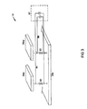
- FIG. 1 is an exploded illustration of a fuel cell incorporating the sensor plate of the present invention
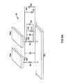
- FIG. 2A is a schematic representation of the current flow path through a fuel cell having the sensor plate of the present invention
- FIG. 2B is a schematic representation of alternative current flow paths through a fuel cell having a sensor plate
- FIG. 3 is a schematic of the instrumentation for monitoring the voltage drop across each current sense resistor
- FIG. 4 is a top view of a portion of the first flow field plate segmented into a plurality of electrically isolated regions and having connection points for the first connection lead of a resistor;
- FIG. 5 is an illustration of the instrumentation for monitoring the temperature distribution plus voltage monitoring instrumentation
- FIG. 6A is an illustration of the instrumentation for monitoring both the current and temperature distribution
- FIG. 6B is an illustration of the monitoring instrumentation for measuring current and temperature distribution using resistors instead of current sources
- FIG. 7 is a partial view of a portion of the circuit board showing the electrical traces for coupling the resistors to a terminal block;
- FIG. 8 is a top view of a portion of the resistor array located on the circuit board.
- FIG. 9 is a top view of a portion of the connections points for the second connection lead of the resistor to the second flow field plate.
- the present invention provides a means to monitor the current distribution of an operating fuel cell using a sensor plate.
- the anode and cathode flow field plates of a fuel cell bipolar plate are electrically separated from one another with an array of resistors between such anode and cathode flow field plates.
- the method of the invention relies upon the relationship between the current traveling through any resistor of the array and the current leaving a region of the membrane electrode assembly (MEA) directly adjacent to that resistor. Then, the distribution of the current leaving an entire fuel cell is determinable by the array of resistors across the entire cross-sectional area of the cell.
- MEA membrane electrode assembly
- the current passing through a particular resistor is determined by measuring the voltage drop across such resistor.
- the current produced by an MEA is determined as a function of position, by measuring the voltage drops across each resistor in the array. In other words, current as a function of position across the MEA, is monitored.
- the array comprises temperature-sensing resistors, that is, thermistors, with each thermistor associated with a different region of the MEA.
- the assembly comprises respective arrays of thermistors and current-sensing resistors. The method of the invention relies upon the relationship between the temperature sensed by a thermistor being representative of the temperature of a region of the MEA directly adjacent to that thermistor. Then, the distribution of the temperature across an entire fuel cell is determinable by the array of thermistors across the entire cross-sectional area of the cell.
- each thermistor is determined by measuring the voltage drop across each thermistor. In this manner, the temperature of an MEA is determined as a function of position by measuring the voltage drops across each thermistor in the array. In other words, temperature as a function of position across the MEA, is monitored.
- FIG. 1 schematically depicts a partial fuel cell stack 6 having a pair of MEAs 8 and 10 separated from each other by a non-porous, electrically-conductive bipolar plate 12 which includes the sensor plate of the present invention.
- Each of the MEAs 8 , 10 have a cathode face 8 c , 10 c and an anode face 8 a , 10 a .
- the MEAs 8 , 10 , and bipolar plate 12 are stacked together between non-porous, electrically-conductive bipolar plates 14 , 16 .
- the plates 12 , 14 , 16 each include flow fields 18 , 20 and 22 having a plurality of flow channels formed in a face of the plates for distributing fuel and oxidant gases (i.e., H 2 & O 2 ) to the reactive faces of the MEAs 8 , 10 .
- fuel and oxidant gases i.e., H 2 & O 2
- Porous, gas permeable, electrically-conductive sheets 34 , 36 , 38 , 40 press up against the electrode faces of the MEAs 8 , 10 and serve as primary current collectors for the electrodes.
- Primary current collectors 34 - 40 also provide mechanical support for the MEAs 8 , 10 , especially at locations where the MEAs are otherwise unsupported in the flow field.
- Bipolar plates 14 , 16 press up against the primary current collector 34 on the cathode face 8 c of MEA 8 and the primary current collector 40 on the anode face 10 a of MEA 10 , respectively.
- Bipolar plate 12 presses up against the primary current collector 36 on the anode face 8 a of MEA 8 and against the primary current collector 38 on the cathode face 10 c of MEA 10 .
- An oxidant gas such as oxygen or air
- a storage tank 46 via appropriate supply plumbing 42 .
- the oxygen tank 46 may be eliminated and air supplied to the cathode side from the ambient environment.
- a fuel such as hydrogen
- the hydrogen tank 48 may be eliminated and the anode feed stream may be supplied from a reformer which catalytically dissociates hydrogen from a hydrocarbon fuel.
- Exhaust plumbing (not shown) for the reactant gases exhausted from the fuel cell stack 6 is also provided for removing anode effluent from the anode flow field and cathode effluent from the cathode flow field.
- Coolant plumbing 50 , 52 is provided for supplying and exhausting a coolant fluid to the bipolar plates 12 , 14 , 16 , as needed.
- FIG. 2A is a schematic illustration of the current flow path through a fuel cell assembly that includes the current distribution sensor plate 12 .
- the load circuit of the invention is the current produced by the operation of the fuel cell.
- Sensor plate 12 comprises a cathode flow field plate 20 c , an anode flow field plate 20 a , and a circuit board 80 .
- Circuit board 80 comprises an array of current-sensing resistors 60 , 62 that connect the anode and cathode flow field plates 20 a , 20 c .
- Above the anode flow field plate 20 a is a diffusion media sheet 36 .
- reference number 76 represents the electrical contact resistance between anode flow field plate 20 a and diffusion media sheet 36 .
- MEA 34 which is the element for which the current distribution is being measured.
- Each of the physical elements of the assembly shown in FIG. 2A have a nominal electrical resistance associated with them.
- the resistance value of a particular element of the assembly can also be anisotropic, meaning that an element's resistance in the through-plane direction may be different from its resistance in the in-plane direction. Because of this, each physical element has separate reference numbers representing the respective electrical resistance in the in-plane and through-plane directions. The areas of resistance in the in-plane and through-plane directions function as resistive elements. These terms are used interchangeably herein.
- the method of the invention relies upon the relationship that the current traveling through a particular current-sensing resistor 60 , 62 is representative of the same value of current that is leaving the region of the MEA 34 directly above that current-sensing resistor 60 , 62 .
- This relationship is a function of the contact resistance or inherent resistive values in each of the assembled elements. Accordingly, it is assumed that most of the current entering diffusion media 36 at the area associated with reference number 72 leaves circuit board 80 through the current-sensing resistor 60 . Similarly, most of the current entering diffusion media 36 at the area represented by reference number 73 leaves circuit board 80 through current-sensing resistor 62 .
- the values of current sense resistors 60 and 62 must be selected to have relatively low resistance values with respect to the values of the through-plane bulk and contact resistances 74 , 75 , 76 , 77 , and 78 , and the in-plane resistance values of the areas represented by reference numbers 68 and 70 .
- each bulk region associated with reference numbers 70 , 77 , and 78 of the anode flow field plate 20 a are much lower than any other resistors in the network.
- the anode flow field plate 20 a has a relatively low in-plane resistance value represented by reference number 70 (typically on the order of 100 ⁇ ) which readily allows current to travel in the through-plane direction of the anode flow field plate 20 a instead of being transmitted in the in-plane direction.
- the area represented by reference number 70 must be segmented or electrically isolated to eliminate the in-plane current flow.
- FIG. 4 illustrates the segmentation of a portion of the anode flow field plate 20 a that takes place in order to electrically isolate this current path. Segmenting the anode flow field plate 20 a effectively removes the low resistance area represented by reference number 70 from the circuit, creating electrically isolated regions for the current paths.
- the present invention describes using the anode flow field plate 20 a as the segmented plate. Segmenting the field associated with the fuel (i.e., the anode flow field plate) minimizes the disturbance of the reactant gases flowing through the fuel cell.
- the present invention could utilize a segmented cathode flow field plate 20 c in place of or in addition to the segmented anode flow field plate 20 a.
- the resistance to current travel through the diffusion media 36 is, on the other hand, large enough (typically in the range of 80-100 m ⁇ ) so that the electrical leakage path can remain connected without substantially reducing measurement accuracy.
- the leakage path represented by reference number 68 is, in fact, two parallel pathways. Both are schematically illustrated in FIG. 2 B.
- Both pathways cross from one segmented region of the anode flow field plate 20 a to the next through the region of the diffusion media 36 that sits over the gap where the anode flow field plate 20 a was segmented.
- This electrical pathway is represented by reference number 68 a .
- current may be delivered to the area represented by reference number 68 a through two different paths: one path allows current to travel through the diffusion media 36 to the next through-plane path of the fuel cell, and the other path allows current to jump from the diffusion media 36 down into the anode flow field plate 20 a , across the anode flow field plate 20 a to the edge of the segmented region, then back up into the diffusion media 36 .
- Reference numbers 74 , 76 a , 76 b , and 79 represent the second pathway in which current can travel through the anode flow field plate 20 a .
- This path does not diminish measurement accuracy because the contact resistance represented by reference numbers 76 a , 76 b , and 76 c between the diffusion media 36 and the anode flow field plate 20 a raises the resistance of this path.
- the electrical path represented by reference numbers 68 a and 68 b need not be cut, thus avoiding the need to segment the diffusion media layer 36 .
- the circuit board 80 is constructed of a non-conductive material, thereby causing no current leakage across the circuit board 80 .
- Each current-sensing resistor 60 , 62 on the circuit board 80 has a first connection lead coupling the current-sensing resistor 60 , 62 to the anode flow field plate 20 a .
- the current-sensing resistor 60 , 62 will also have a second connection lead coupling the current-sensing resistor 60 , 62 to a common or ground 74 .
- a second connection lead couples the current-sensing resistor 60 , 62 to the cathode flow field plate 20 c.
- the resistor values used in the sensor plate 12 should be low relative to the in-plane resistance represented by reference number 68 of the diffusion media 36 .
- resistor 60 , 62 should be an order of magnitude less than the diffusion media 36 (typically in the range of less than 10 m ⁇ ).
- the area of the diffusion media 36 represented by reference number 68 will determine the resistor value of the sensor plate 12 .
- the resistance of the current-sensing resistor 60 , 62 approaches the bulk resistance of the diffusion media 36 , current is re-distributed through the diffusion media 36 instead of through current-sensing resistor 60 , 62 of the sensor plate 12 . If such distribution occurs, the sensor plate 12 becomes ineffective for measuring current within the segmented regions and instead provides an overall average current distribution across the face of the cell instead of the desired current measurement of each segmented region.
- FIG. 3 is an electrical schematic of the current distribution sensor plate 12 that includes an illustration of the monitoring instrumentation used to measure the voltage drop across each current-sense resistor 60 , 62 .
- electrically isolated regions of the anode flow field plate, 20 a 1 and 20 a 2 are electrically connected to cathode flow field plate 20 c through known value current-sensing resistors 60 and 62 .
- Each resistor 60 , 62 is connected to a pair of voltage sense leads, 64 and 66 , via contact pads (not shown), and extend out of the sensor plate 12 to a high-channel count DC voltmeter 67 .
- a DC voltmeter 67 is used to convert analog measurements of the voltage drop across each current-sense resistor 60 , 62 into digital values that indicate the amount of current leaving the region of the MEA 34 directly adjacent to each particular resistor 60 , 62 . By displaying these values in the form of an intensity plot, the current distribution of a fuel cell is revealed.
- temperature distribution of a fuel cell is monitored in a manner similar to that described for current distribution. This is accomplished by placing thermistors in an array similar to the current-sensing resistors described above.
- FIG. 5 is a schematic illustration of a fuel cell incorporating the temperature distribution sensor plate 14 , that includes voltage monitoring instrumentation.
- the fuel cell load circuit and the temperature-sensing circuit are electrically isolated from one another. However, thermal energy produced in the load circuit is transferred through to the assembly, thus the load circuit and the temperature-sensing circuits are thermally connected. In other words, the temperature environment of the MEA in the load circuit is essentially the same temperature environment to which the thermistor, in the temperature-sensing circuit, is exposed.
- thermistors 100 and 102 To determine the temperature at any given point along the MEA 34 , a known current is delivered to thermistors 100 and 102 by current sources 110 and 112 which is drawn from an external load. The voltage drop across thermistors 100 and 102 is measured by DC voltmeters 120 and 122 . With knowledge of the temperature coefficients of the thermistors 100 and 102 and the current flowing therethrough, the analog voltage drops of the thermistors 100 and 102 is measured by the DC voltmeters 120 and 122 and converted to values representing the temperature at the location of thermistors 100 and 102 . The array of thermistors across the entire cross-sectional area of the flow field plate of a fuel cell permits the temperature distribution of a complete fuel cell to be monitored.
- current monitoring and temperature monitoring is combined into a single sensor plate assembly.
- This embodiment is the most advantageous for three reasons: (1) only a single sensor plate is added to the fuel cell to obtain both current and temperature measurements, (2) the same high-channel DC voltmeter instrumentation is used for monitoring both the current and temperature measurements, by incorporating appropriate switching into the instrumentation, and (3) fewer sense leads may be used because such leads serve more than one purpose.
- FIG. 6A is a schematic illustration of a fuel cell incorporating the current/temperature distribution sensor plate 16 , including the monitoring instrumentation to support both measurements.
- Segmented anode flow field plate elements 20 a 1 and 20 a 2 are connected to cathode flow field plate 20 a by current-sensing resistors 60 and 62 .
- the resistors 60 , 62 are connected to the voltage sense leads 64 and 66 , via contact pads, and are extended back to the DC voltmeters 120 and 122 , similar to the current distribution embodiment.
- thermistors 100 and 102 are inserted into one leg of the voltage sense lead pairs.
- a series combination of current sources 110 and 112 and switches 130 and 132 are added in parallel with DC voltmeters 120 and 122 . The position of switches 130 and 132 determine whether current or temperature is being monitored.
- current-sensing resistors 60 and 62 are selected to have low resistance values in order to inhibit or prevent lateral flow of current during current distribution measurement.
- thermistors 100 and 102 are selected to have resistance values higher than that of the current-sensing resistors 60 and 62 , the voltage drop across 60 and 62 becomes negligible. In this way, DC voltmeters 120 and 122 monitor the voltage drop of thermistors 100 and 102 without voltage contribution from current-sensing resistors 60 and 62 .
- current sources ( 110 , 112 of FIG. 6) used for temperature measurement are replaced with a resistor 140 , 142 which draws current from the load circuit of the fuel cell.
- a small known current is drawn from the load circuit by a resistor 140 , 142 , instead of being added to the load circuit as described in the previous embodiment. This is accomplished by adding a reference resistor 140 , 142 in series with the switch 130 , 132 , and by properly sizing both the reference resistor 140 , 142 and thermistor 100 , 102 so that their total resistance, relative to the shunt, is large enough to pull only a negligible current off of the load.
- the anode flow field plate 20 a is segmented into a plurality of electrically-isolated regions 86 .
- the anode flow field plate 20 a is segmented by cutting separate channels using a cutting device, such as a laser jet cutter, leaving only a minor attachment at the corners thereof. Care is used to ensure that the flow field of the segmented plate is not disrupted. Segmenting the anode flow field plate 20 a electrically-isolates the segmented regions 20 a 1 , 20 a 2 of the anode flow field plate 20 a . After the anode flow field plate 20 a is segmented, it is electrically coupled to the circuit board by soldering or other suitable means.
- the minor attachments remaining at the corners of the segmented plate are cut using a cutting device, allowing the electrically isolated regions 86 of the anode flow field plate 20 a to be completely isolated from one another. Any disruptions in the flow field may be eliminated by locally filling the region with an epoxy or the like to preserve the integrity of the flow field.
- the anode flow field plate 20 a has connection points 88 located within each electrically-isolated region 86 wherein the first connection lead of a current-sensing resistor 60 , 62 associated with that electrically isolated region 86 can connect to the anode flow field plate 20 a.
- circuit board 80 is shown with electrical traces 90 connecting the contact pads (only 84 a is shown) and extending to an edge connector or terminal block 94 .
- FIG. 8 a portion of the circuit board 80 is shown wherein the current-sensing resistors 60 , 62 are arranged in an array.
- the number and arrangement of the current-sensing resistor array may be modified in accordance with the size and the configuration of the flow field plate to be measured.
- the resistors can be arranged in any manner that is appropriate to the design of the flow field and the segmented regions of the flow field plate.
- the cathode flow field plate 20 c is shown with the connection points 92 that correspond to the second connection lead of a current-sensing resistor 60 , 62 associated with that electrically-isolated region 86 .
Landscapes
- Life Sciences & Earth Sciences (AREA)
- Chemical & Material Sciences (AREA)
- Electrochemistry (AREA)
- Health & Medical Sciences (AREA)
- Chemical Kinetics & Catalysis (AREA)
- Biochemistry (AREA)
- Pathology (AREA)
- Analytical Chemistry (AREA)
- Molecular Biology (AREA)
- General Health & Medical Sciences (AREA)
- General Physics & Mathematics (AREA)
- Immunology (AREA)
- Physics & Mathematics (AREA)
- Engineering & Computer Science (AREA)
- Manufacturing & Machinery (AREA)
- Sustainable Development (AREA)
- Sustainable Energy (AREA)
- General Chemical & Material Sciences (AREA)
- Fuel Cell (AREA)
Abstract
Description
Claims (24)
Priority Applications (4)
| Application Number | Priority Date | Filing Date | Title |
|---|---|---|---|
| US10/206,140 US6828053B2 (en) | 2002-07-26 | 2002-07-26 | In-situ resistive current and temperature distribution circuit for a fuel cell |
| AU2003256750A AU2003256750A1 (en) | 2002-07-26 | 2003-07-24 | In-situ resistive current and temperature distribution circuit for a fuel cell |
| DE10392974T DE10392974B4 (en) | 2002-07-26 | 2003-07-24 | Sensor arrangement for the local power and temperature distribution for a fuel cell |
| PCT/US2003/023143 WO2004012282A2 (en) | 2002-07-26 | 2003-07-24 | In-situ resistive current and temperature distribution circuit for a fuel cell |
Applications Claiming Priority (1)
| Application Number | Priority Date | Filing Date | Title |
|---|---|---|---|
| US10/206,140 US6828053B2 (en) | 2002-07-26 | 2002-07-26 | In-situ resistive current and temperature distribution circuit for a fuel cell |
Publications (2)
| Publication Number | Publication Date |
|---|---|
| US20040018401A1 US20040018401A1 (en) | 2004-01-29 |
| US6828053B2 true US6828053B2 (en) | 2004-12-07 |
Family
ID=30770225
Family Applications (1)
| Application Number | Title | Priority Date | Filing Date |
|---|---|---|---|
| US10/206,140 Expired - Lifetime US6828053B2 (en) | 2002-07-26 | 2002-07-26 | In-situ resistive current and temperature distribution circuit for a fuel cell |
Country Status (4)
| Country | Link |
|---|---|
| US (1) | US6828053B2 (en) |
| AU (1) | AU2003256750A1 (en) |
| DE (1) | DE10392974B4 (en) |
| WO (1) | WO2004012282A2 (en) |
Cited By (4)
| Publication number | Priority date | Publication date | Assignee | Title |
|---|---|---|---|---|
| US20050271906A1 (en) * | 2004-06-08 | 2005-12-08 | Murphy Michael W | Integrated switching assemblies for a fuel cell stack |
| US20060141326A1 (en) * | 2004-12-28 | 2006-06-29 | Artibise Robert H | Integrated current collector and electrical component plate for a fuel cell stack |
| US20060188770A1 (en) * | 2005-02-24 | 2006-08-24 | Hsi-Ming Shu | Compound flow field board for fuel cell |
| US20140327445A1 (en) * | 2011-09-05 | 2014-11-06 | Kabushiki Kaisha Nihon Micronics | Evaluation apparatus and evaluation method of sheet type cell |
Families Citing this family (25)
| Publication number | Priority date | Publication date | Assignee | Title |
|---|---|---|---|---|
| DE10316117B3 (en) * | 2003-04-04 | 2004-04-29 | Deutsches Zentrum für Luft- und Raumfahrt e.V. | Device for measuring local current/heat distribution on electrochemical electrode has current flow direction to resistance element transverse to current flow direction to current conducting element |
| DE102004014493B4 (en) * | 2004-03-23 | 2006-11-02 | Forschungszentrum Jülich GmbH | Method for determining the current density distribution in fuel cells |
| DE102004014114A1 (en) * | 2004-03-23 | 2005-10-20 | Forschungszentrum Juelich Gmbh | Device for determining the current density distribution in fuel cells |
| US8288046B2 (en) * | 2004-09-29 | 2012-10-16 | GM Global Technology Operations LLC | Integrated current sensors for a fuel cell stack |
| JP4854237B2 (en) * | 2004-10-22 | 2012-01-18 | 日産自動車株式会社 | Solid oxide fuel cell and stack structure |
| US8039157B2 (en) * | 2004-12-21 | 2011-10-18 | Nissan Motor Co., Ltd. | Startup method for fuel cell stack structure, temperature control method for fuel cell stack structure, and fuel cell stack structure |
| DE102006005340A1 (en) * | 2006-02-07 | 2007-08-09 | Volkswagen Ag | Detecting device for operational data of fuel cell in fuel cell stack, has sensor plate integrated into fuel cell stack |
| JP4963373B2 (en) * | 2006-04-19 | 2012-06-27 | 株式会社日本自動車部品総合研究所 | Fuel cell internal state observation device |
| DE102006051320B4 (en) * | 2006-10-24 | 2008-09-18 | Fraunhofer-Gesellschaft zur Förderung der angewandten Forschung e.V. | Fuel cell assembly, a test rig containing them and method for their preparation |
| DE102007034699A1 (en) * | 2007-07-16 | 2009-01-22 | Deutsches Zentrum für Luft- und Raumfahrt e.V. | Measuring device and method for determining the electrical potential and / or the current density at an electrode |
| DE102007058837A1 (en) * | 2007-12-05 | 2009-06-10 | Technische Universität Clausthal | Electrochemical energy conversion system |
| CN102116680B (en) * | 2011-02-18 | 2012-07-11 | 北京工业大学 | Insertion sheet for measuring internal temperature distribution of fuel cell |
| JP5708219B2 (en) * | 2011-05-11 | 2015-04-30 | 株式会社デンソー | Current measuring device |
| JP5655707B2 (en) * | 2011-05-25 | 2015-01-21 | 株式会社デンソー | Impedance measuring device |
| FR2985610A1 (en) * | 2012-01-09 | 2013-07-12 | Commissariat Energie Atomique | METHOD FOR DETERMINING LOCAL CURRENT DISTRIBUTION INTO A HEAD OF PROTON EXCHANGE MEMBRANE FUEL CELL |
| JP5853834B2 (en) * | 2012-04-09 | 2016-02-09 | 株式会社デンソー | Current measuring device |
| JP5987639B2 (en) * | 2012-11-01 | 2016-09-07 | 株式会社デンソー | Current measuring device |
| JP6070478B2 (en) * | 2013-08-22 | 2017-02-01 | 株式会社デンソー | Current measuring device and manufacturing method thereof |
| JP6120078B2 (en) * | 2013-08-22 | 2017-04-26 | 株式会社デンソー | Current measuring device |
| JP6459873B2 (en) * | 2015-09-18 | 2019-01-30 | 株式会社デンソー | Current measuring device |
| DE102018102471B3 (en) * | 2018-02-05 | 2019-02-21 | Leoni Kabel Gmbh | Apparatus and method for measuring a temperature distribution on a surface |
| CN112229537B (en) * | 2020-09-17 | 2021-12-03 | 电子科技大学 | Subarea test system for detecting current and temperature distribution of fuel cell |
| CN112212991B (en) * | 2020-10-10 | 2022-01-25 | 电子科技大学 | Fuel cell tip temperature distribution on-line measuring device |
| CN118443175B (en) * | 2024-04-17 | 2025-12-12 | 北京卫星制造厂有限公司 | A contact-type fuel cell stack internal temperature measurement device and method |
| DE102024111628A1 (en) | 2024-04-25 | 2025-10-30 | Deutsches Zentrum für Luft- und Raumfahrt e.V. | Measuring device, electrochemical energy converter and method for measuring a local current distribution and/or a local heat distribution in an electrochemical energy converter |
Citations (4)
| Publication number | Priority date | Publication date | Assignee | Title |
|---|---|---|---|---|
| US20020090540A1 (en) * | 1998-11-09 | 2002-07-11 | Johann Einhart | Electrical contacting device for an electrochemical fuel cell |
| US20020094460A1 (en) * | 2001-01-08 | 2002-07-18 | Hortop Matthew K. | Fuel cell stack coolant conductivity sensor using differential voltage measurements |
| US6541147B1 (en) | 1998-07-01 | 2003-04-01 | Ballard Power Systems Inc. | Printed circuit board separator for an electrochemical fuel cell |
| US20040048113A1 (en) * | 2002-09-06 | 2004-03-11 | Murphy Michael W. | Method for detecting electrical defects in membrane electrode assemblies |
Family Cites Families (2)
| Publication number | Priority date | Publication date | Assignee | Title |
|---|---|---|---|---|
| US5945232A (en) * | 1998-04-03 | 1999-08-31 | Plug Power, L.L.C. | PEM-type fuel cell assembly having multiple parallel fuel cell sub-stacks employing shared fluid plate assemblies and shared membrane electrode assemblies |
| US6724194B1 (en) * | 2000-06-30 | 2004-04-20 | Ballard Power Systems Inc. | Cell voltage monitor for a fuel cell stack |
-
2002
- 2002-07-26 US US10/206,140 patent/US6828053B2/en not_active Expired - Lifetime
-
2003
- 2003-07-24 AU AU2003256750A patent/AU2003256750A1/en not_active Abandoned
- 2003-07-24 DE DE10392974T patent/DE10392974B4/en not_active Expired - Lifetime
- 2003-07-24 WO PCT/US2003/023143 patent/WO2004012282A2/en not_active Ceased
Patent Citations (4)
| Publication number | Priority date | Publication date | Assignee | Title |
|---|---|---|---|---|
| US6541147B1 (en) | 1998-07-01 | 2003-04-01 | Ballard Power Systems Inc. | Printed circuit board separator for an electrochemical fuel cell |
| US20020090540A1 (en) * | 1998-11-09 | 2002-07-11 | Johann Einhart | Electrical contacting device for an electrochemical fuel cell |
| US20020094460A1 (en) * | 2001-01-08 | 2002-07-18 | Hortop Matthew K. | Fuel cell stack coolant conductivity sensor using differential voltage measurements |
| US20040048113A1 (en) * | 2002-09-06 | 2004-03-11 | Murphy Michael W. | Method for detecting electrical defects in membrane electrode assemblies |
Non-Patent Citations (1)
| Title |
|---|
| S.J.C. Cleghorn, C.R. Derouin, M.S. Wilson, S. Gottesfeld; A Printed Circuit Board Approach To Measuring Current Distribution In A Fuel Cell; Journal of Applied Electrochemistry 28 (1998) 663-672, no month. |
Cited By (7)
| Publication number | Priority date | Publication date | Assignee | Title |
|---|---|---|---|---|
| US20050271906A1 (en) * | 2004-06-08 | 2005-12-08 | Murphy Michael W | Integrated switching assemblies for a fuel cell stack |
| US7611784B2 (en) * | 2004-06-08 | 2009-11-03 | Gm Global Technology Operations, Inc. | Integrated switching assemblies for a fuel cell stack |
| US20060141326A1 (en) * | 2004-12-28 | 2006-06-29 | Artibise Robert H | Integrated current collector and electrical component plate for a fuel cell stack |
| US7488551B2 (en) * | 2004-12-28 | 2009-02-10 | Ballard Power Systems Inc. | Integrated current collector and electrical component plate for a fuel cell stack |
| US20060188770A1 (en) * | 2005-02-24 | 2006-08-24 | Hsi-Ming Shu | Compound flow field board for fuel cell |
| US20140327445A1 (en) * | 2011-09-05 | 2014-11-06 | Kabushiki Kaisha Nihon Micronics | Evaluation apparatus and evaluation method of sheet type cell |
| US10036780B2 (en) * | 2011-09-05 | 2018-07-31 | Kabushiki Kaisha Nihon Micronics | Evaluation apparatus and evaluation method of sheet type cell |
Also Published As
| Publication number | Publication date |
|---|---|
| DE10392974B4 (en) | 2007-07-19 |
| WO2004012282A3 (en) | 2004-07-01 |
| AU2003256750A8 (en) | 2004-02-16 |
| US20040018401A1 (en) | 2004-01-29 |
| DE10392974T5 (en) | 2005-08-25 |
| AU2003256750A1 (en) | 2004-02-16 |
| WO2004012282A2 (en) | 2004-02-05 |
Similar Documents
| Publication | Publication Date | Title |
|---|---|---|
| US6828053B2 (en) | In-situ resistive current and temperature distribution circuit for a fuel cell | |
| US6949920B2 (en) | Apparatus for measuring current density of fuel cell | |
| US8288046B2 (en) | Integrated current sensors for a fuel cell stack | |
| US7488551B2 (en) | Integrated current collector and electrical component plate for a fuel cell stack | |
| CN100527505C (en) | Circuit connection control system of fuel cell and method of operating the same | |
| JP2014522557A (en) | Fuel cell bypass diode structure and mounting method | |
| JP2010080164A (en) | Current measurement device | |
| JP5474839B2 (en) | Fuel cell current density distribution measuring device | |
| US20040018407A1 (en) | Electrochemical cell stack design | |
| JPH09223512A (en) | Fuel cell abnormality monitoring method and apparatus | |
| CN101199073B (en) | Fuel cell system designed to ensure operational stability | |
| JP6632611B2 (en) | Fuel cell for detecting pollutants | |
| JP4887708B2 (en) | Fuel cell system | |
| US20150162630A1 (en) | Multi-point fuel cell voltage monitor | |
| JP5078573B2 (en) | Fuel cell system | |
| JP2007311204A (en) | Fuel cell current distribution measurement device, stacked fuel cell current distribution measurement device, and fuel cell current distribution measurement method | |
| JPH09306519A (en) | Phosphoric acid fuel cell power generator | |
| JP5060023B2 (en) | Fuel cell and fuel cell module | |
| JP2015022856A (en) | Impedance measuring device for fuel cell | |
| JP2005203158A (en) | Fuel cell monitoring device | |
| JP5945466B2 (en) | Potential measurement device for fuel cell | |
| JP5708219B2 (en) | Current measuring device | |
| JPH0456074A (en) | Sensor fitting device for measuring fuel cell | |
| JP2005183039A (en) | Method for measuring current distribution of stacked fuel cell, stacked fuel cell, and operation method of stacked fuel cell | |
| JP5829580B2 (en) | Potential measurement device for fuel cell |
Legal Events
| Date | Code | Title | Description |
|---|---|---|---|
| AS | Assignment |
Owner name: GENERAL MOTORS CORPORATION, MICHIGAN Free format text: ASSIGNMENT OF ASSIGNORS INTEREST;ASSIGNORS:FLY, GERALD W.;MURPHY, MICHAEL W.;FUSS, ROBERT L.;AND OTHERS;REEL/FRAME:013318/0241;SIGNING DATES FROM 20020910 TO 20020912 |
|
| STCF | Information on status: patent grant |
Free format text: PATENTED CASE |
|
| FPAY | Fee payment |
Year of fee payment: 4 |
|
| AS | Assignment |
Owner name: GM GLOBAL TECHNOLOGY OPERATIONS, INC., MICHIGAN Free format text: ASSIGNMENT OF ASSIGNORS INTEREST;ASSIGNOR:GENERAL MOTORS CORPORATION;REEL/FRAME:022092/0737 Effective date: 20050119 Owner name: GM GLOBAL TECHNOLOGY OPERATIONS, INC.,MICHIGAN Free format text: ASSIGNMENT OF ASSIGNORS INTEREST;ASSIGNOR:GENERAL MOTORS CORPORATION;REEL/FRAME:022092/0737 Effective date: 20050119 |
|
| AS | Assignment |
Owner name: UNITED STATES DEPARTMENT OF THE TREASURY, DISTRICT Free format text: SECURITY AGREEMENT;ASSIGNOR:GM GLOBAL TECHNOLOGY OPERATIONS, INC.;REEL/FRAME:022201/0547 Effective date: 20081231 Owner name: UNITED STATES DEPARTMENT OF THE TREASURY,DISTRICT Free format text: SECURITY AGREEMENT;ASSIGNOR:GM GLOBAL TECHNOLOGY OPERATIONS, INC.;REEL/FRAME:022201/0547 Effective date: 20081231 Owner name: UNITED STATES DEPARTMENT OF THE TREASURY, DISTRICT OF COLUMBIA Free format text: SECURITY AGREEMENT;ASSIGNOR:GM GLOBAL TECHNOLOGY OPERATIONS, INC.;REEL/FRAME:022201/0547 Effective date: 20081231 |
|
| AS | Assignment |
Owner name: CITICORP USA, INC. AS AGENT FOR BANK PRIORITY SECU Free format text: SECURITY AGREEMENT;ASSIGNOR:GM GLOBAL TECHNOLOGY OPERATIONS, INC.;REEL/FRAME:022553/0399 Effective date: 20090409 Owner name: CITICORP USA, INC. AS AGENT FOR HEDGE PRIORITY SEC Free format text: SECURITY AGREEMENT;ASSIGNOR:GM GLOBAL TECHNOLOGY OPERATIONS, INC.;REEL/FRAME:022553/0399 Effective date: 20090409 Owner name: CITICORP USA, INC. AS AGENT FOR BANK PRIORITY SECURED PARTIES, DELAWARE Free format text: SECURITY AGREEMENT;ASSIGNOR:GM GLOBAL TECHNOLOGY OPERATIONS, INC.;REEL/FRAME:022553/0399 Effective date: 20090409 Owner name: CITICORP USA, INC. AS AGENT FOR HEDGE PRIORITY SECURED PARTIES, DELAWARE Free format text: SECURITY AGREEMENT;ASSIGNOR:GM GLOBAL TECHNOLOGY OPERATIONS, INC.;REEL/FRAME:022553/0399 Effective date: 20090409 |
|
| AS | Assignment |
Owner name: GM GLOBAL TECHNOLOGY OPERATIONS, INC., MICHIGAN Free format text: RELEASE BY SECURED PARTY;ASSIGNOR:UNITED STATES DEPARTMENT OF THE TREASURY;REEL/FRAME:023124/0470 Effective date: 20090709 Owner name: GM GLOBAL TECHNOLOGY OPERATIONS, INC.,MICHIGAN Free format text: RELEASE BY SECURED PARTY;ASSIGNOR:UNITED STATES DEPARTMENT OF THE TREASURY;REEL/FRAME:023124/0470 Effective date: 20090709 |
|
| AS | Assignment |
Owner name: GM GLOBAL TECHNOLOGY OPERATIONS, INC., MICHIGAN Free format text: RELEASE BY SECURED PARTY;ASSIGNORS:CITICORP USA, INC. AS AGENT FOR BANK PRIORITY SECURED PARTIES;CITICORP USA, INC. AS AGENT FOR HEDGE PRIORITY SECURED PARTIES;REEL/FRAME:023127/0273 Effective date: 20090814 Owner name: GM GLOBAL TECHNOLOGY OPERATIONS, INC.,MICHIGAN Free format text: RELEASE BY SECURED PARTY;ASSIGNORS:CITICORP USA, INC. AS AGENT FOR BANK PRIORITY SECURED PARTIES;CITICORP USA, INC. AS AGENT FOR HEDGE PRIORITY SECURED PARTIES;REEL/FRAME:023127/0273 Effective date: 20090814 |
|
| AS | Assignment |
Owner name: UNITED STATES DEPARTMENT OF THE TREASURY, DISTRICT Free format text: SECURITY AGREEMENT;ASSIGNOR:GM GLOBAL TECHNOLOGY OPERATIONS, INC.;REEL/FRAME:023156/0001 Effective date: 20090710 Owner name: UNITED STATES DEPARTMENT OF THE TREASURY,DISTRICT Free format text: SECURITY AGREEMENT;ASSIGNOR:GM GLOBAL TECHNOLOGY OPERATIONS, INC.;REEL/FRAME:023156/0001 Effective date: 20090710 |
|
| AS | Assignment |
Owner name: UAW RETIREE MEDICAL BENEFITS TRUST, MICHIGAN Free format text: SECURITY AGREEMENT;ASSIGNOR:GM GLOBAL TECHNOLOGY OPERATIONS, INC.;REEL/FRAME:023161/0911 Effective date: 20090710 Owner name: UAW RETIREE MEDICAL BENEFITS TRUST,MICHIGAN Free format text: SECURITY AGREEMENT;ASSIGNOR:GM GLOBAL TECHNOLOGY OPERATIONS, INC.;REEL/FRAME:023161/0911 Effective date: 20090710 |
|
| AS | Assignment |
Owner name: GM GLOBAL TECHNOLOGY OPERATIONS, INC., MICHIGAN Free format text: RELEASE BY SECURED PARTY;ASSIGNOR:UAW RETIREE MEDICAL BENEFITS TRUST;REEL/FRAME:025311/0725 Effective date: 20101026 Owner name: GM GLOBAL TECHNOLOGY OPERATIONS, INC., MICHIGAN Free format text: RELEASE BY SECURED PARTY;ASSIGNOR:UNITED STATES DEPARTMENT OF THE TREASURY;REEL/FRAME:025245/0347 Effective date: 20100420 |
|
| AS | Assignment |
Owner name: WILMINGTON TRUST COMPANY, DELAWARE Free format text: SECURITY AGREEMENT;ASSIGNOR:GM GLOBAL TECHNOLOGY OPERATIONS, INC.;REEL/FRAME:025327/0262 Effective date: 20101027 |
|
| AS | Assignment |
Owner name: GM GLOBAL TECHNOLOGY OPERATIONS LLC, MICHIGAN Free format text: CHANGE OF NAME;ASSIGNOR:GM GLOBAL TECHNOLOGY OPERATIONS, INC.;REEL/FRAME:025780/0795 Effective date: 20101202 |
|
| FPAY | Fee payment |
Year of fee payment: 8 |
|
| AS | Assignment |
Owner name: GM GLOBAL TECHNOLOGY OPERATIONS LLC, MICHIGAN Free format text: RELEASE BY SECURED PARTY;ASSIGNOR:WILMINGTON TRUST COMPANY;REEL/FRAME:034183/0680 Effective date: 20141017 |
|
| FPAY | Fee payment |
Year of fee payment: 12 |