US6801586B1 - OFDM communication apparatus and propagation path estimation method - Google Patents
OFDM communication apparatus and propagation path estimation method Download PDFInfo
- Publication number
- US6801586B1 US6801586B1 US09/651,094 US65109400A US6801586B1 US 6801586 B1 US6801586 B1 US 6801586B1 US 65109400 A US65109400 A US 65109400A US 6801586 B1 US6801586 B1 US 6801586B1
- Authority
- US
- United States
- Prior art keywords
- propagation path
- signal
- estimated value
- path estimated
- produce
- Prior art date
- Legal status (The legal status is an assumption and is not a legal conclusion. Google has not performed a legal analysis and makes no representation as to the accuracy of the status listed.)
- Expired - Fee Related, expires
Links
Images


Classifications
-
- H—ELECTRICITY
- H04—ELECTRIC COMMUNICATION TECHNIQUE
- H04L—TRANSMISSION OF DIGITAL INFORMATION, e.g. TELEGRAPHIC COMMUNICATION
- H04L25/00—Baseband systems
- H04L25/02—Details ; arrangements for supplying electrical power along data transmission lines
- H04L25/0202—Channel estimation
-
- H—ELECTRICITY
- H04—ELECTRIC COMMUNICATION TECHNIQUE
- H04L—TRANSMISSION OF DIGITAL INFORMATION, e.g. TELEGRAPHIC COMMUNICATION
- H04L27/00—Modulated-carrier systems
- H04L27/26—Systems using multi-frequency codes
- H04L27/2601—Multicarrier modulation systems
- H04L27/2647—Arrangements specific to the receiver only
Definitions
- the present invention relates to an OFDM communication apparatus and propagation path estimation method in a digital radio communication system.
- a leading cause of deterioration of a transmission characteristic in a current ground wave transmission path is multi-path interference.
- An OFDM (Orthogonal Frequency Division Multiplexing) transmission system which is resistant to this multi-path interference, is receiving attention in recent years.
- This OFDM is a system that multiplexes a multiple (several tens to several hundreds) of mutually orthogonal digital modulated signals in a certain signal segment.
- a conventional OFDM communication apparatus calculates a frequency response estimated value of the propagation path by performing time-frequency conversion on a reception signal through an FFT circuit and performing a complex multiplication on a pilot symbol and known signal contained in the reception signal. Then, by carrying out a complex multiplication on the frequency response estimated value and information OFDM symbol, the conventional OFDM communication apparatus compensates propagation path distortion. This reception signal with propagation path distortion compensated is demodulated and subjected to error correction by an error detection circuit and in this way an information bit string, which is reception data, is obtained.
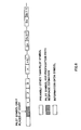
- the conventional OFDM communication apparatus When long information is transmitted, the conventional OFDM communication apparatus above inserts, as shown in FIG. 1, propagation path response estimation pilot symbols (hatched areas) into information OFDM symbols at certain intervals to follow up variations of momentarily changing propagation path response. That is, as shown in FIG. 2, information OFDM symbols 1 to n are compensated using a propagation path estimated value obtained by pilot symbol A and information OFDM symbols n+1 to 2 n are compensated using a propagation path estimated value obtained by pilot symbol B.
- propagation path response estimation pilot symbols hatchched areas
- a subject of the present invention is to adaptively follow up time variations of a transmission path and achieve an excellent reception characteristic by adaptively estimating propagation path response using an error-corrected signal, that is, using a judged value of the received information signal as a known signal without frequently inserting pilot symbols for propagation path estimation and without reducing the transmission efficiency even when long information is transmitted.
- FIG. 1 is a diagram showing a symbol configuration used by a conventional propagation path estimation method
- FIG. 2 is a diagram to explain the conventional propagation path estimation method
- FIG. 3 is a block diagram showing a configuration of an OFDM communication apparatus according to Embodiment 1 of the present invention.
- FIG. 4 is a block diagram showing an internal configuration of a propagation path estimation/compensation circuit of the OFDM communication apparatus according to Embodiment 1 of the present invention
- FIG. 5 is a block diagram showing an internal configuration of the propagation path estimated value update circuit shown in FIG. 4;
- FIG. 6 is a diagram showing a symbol configuration used by a propagation path estimation method according to the present invention.
- FIG. 7 is a diagram to explain the propagation path estimation method according to the present invention.
- FIG. 8 is a block diagram showing an internal configuration of a propagation path estimated value update circuit in a propagation path estimation/compensation circuit of an OFDM communication apparatus according to Embodiment 2 of the present invention.
- FIG. 9 is a block diagram showing an internal configuration of a propagation path estimated value update circuit in a propagation path estimation/compensation circuit of an OFDM communication apparatus according to Embodiment 3 of the present invention.
- FIG. 10 is a block diagram showing an internal configuration of a propagation path estimated value update circuit in a propagation path estimation/compensation circuit of an OFDM communication apparatus according to Embodiment 4 of the present invention.
- FIG. 11 is another block diagram showing the internal configuration of the propagation path estimated value update circuit in the propagation path estimation/compensation circuit of the OFDM communication apparatus according to Embodiment 4 of the present invention.
- FIG. 12 is a block diagram showing an internal configuration of a propagation path estimation/compensation circuit of an OFDM communication apparatus according to Embodiment 5 of the present invention.
- FIG. 13 is a block diagram showing an internal configuration of a propagation path estimated value update circuit in the propagation path estimation/compensation circuit of the OFDM communication apparatus according to Embodiment 5 of the present invention.
- FIG. 14 is a block diagram showing an internal configuration of a propagation path estimated value update circuit in a propagation path estimation/compensation circuit of an OFDM communication apparatus according to Embodiment 6 of the present invention.
- FIG. 15 is a block diagram showing an internal configuration of a propagation path estimated value update circuit in a propagation path estimation/compensation circuit of an OFDM communication apparatus according to Embodiment 7 of the present invention.
- FIG. 16 is another block diagram showing the internal configuration of the propagation path estimated value update circuit in the propagation path estimation/compensation circuit of the OFDM communication apparatus according to Embodiment 7 of the present invention.
- FIG. 3 is a block diagram showing a configuration of an OFDM communication apparatus according to Embodiment 1 of the present invention.
- a signal used for an OFDM communication has a configuration shown in FIG. 6 . That is, the signal has a configuration with a preamble other than a pilot symbol followed by a propagation path response estimation pilot symbol, which is a known signal, and information OFDM symbols. Thus, a propagation path estimation pilot symbol is added only at the start of the information symbol to be transmitted.
- An OFDM signal received through antenna 101 is subjected to normal radio reception processing by radio reception circuit 102 and converted to a baseband signal.
- This baseband signal is subjected to coherent detection processing by a coherent detector, stripped of the unnecessary frequency component by a low-pass filter and converted from analog to digital.
- the reception signal is divided into an in-phase component and quadrature component by the coherent detection processing, but these two components are expressed as one signal path in the figure.
- This baseband signal is subjected to an FFT (Fast Fourier Transform) operation by FFT circuit 103 and in this way signals assigned to different subcarriers are obtained.
- the signal subjected to the FFT operation by FFT section 103 is sent to propagation path estimation/compensation circuit 104 where a first propagation path estimated value (initial value) is obtained by performing propagation path estimation by carrying out a complex multiplication on a pilot symbol and known signal contained in the reception OFDM signal.
- Propagation path estimation/compensation circuit 104 performs propagation path distortion compensation of information OFDM symbols one by one using the first propagation path estimated value.
- the information symbols subjected to propagation path distortion compensation are sent to correction circuit 105 one by one where these symbols are subjected to error correction.
- Error correction circuit 105 outputs an information bit string subjected to error correction for every unit of transmission path coding. This information bit string is sent to error detection circuit 106 where the information bit string is subjected to error detection and output as reception data.
- the information bit string after error correction is periodically sent to re-coding circuit 107 .
- Re-coding circuit 107 performs transmission path coding processing, modulation processing and rearrangement processing on the error-corrected information bit again.
- this re-coded and error-corrected information bit string is sent to propagation path estimation/compensation circuit 104 .
- Propagation path estimation/compensation circuit 104 uses this re-coded information bit as a known signal, performs propagation path estimation by carrying out a complex multiplication with the FFT-operated signal and obtains a propagation path estimated value. This propagation path estimated value is updated to a first propagation path estimated value.
- Propagation path distortion compensation is carried out by performing a complex multiplication on this new first propagation path estimated value and the information OFDM symbol.
- the reception signal with propagation path distortion compensated is sent to error correction circuit 105 where the reception signal is subjected to error correction.
- the information bit string output from error correction circuit 105 is sent to error detection circuit 106 where the information bit string is subjected to error detection and output as reception data.
- the propagation path estimated value can also be updated for every information bit or for every two or more information bits.
- a switch, etc. can be provided after error correction circuit 105 so that the output to re-coding circuit 107 and output to error detection circuit 106 are switched through a control signal.
- an information signal which is transmission data for every subcarrier, is subjected to digital modulation processing by, for example, QPSK (Quadrature Phase Shift Keying) or QAM (Quadrature Amplitude Modulation), etc. and subjected to an IFFT operation by IFFT (Inverse Fast Fourier Transform) circuit 108 and converted to an OFDM signal.
- This OFDM signal is converted from digital to analog, sent to radio transmission circuit 109 where it is subjected to normal radio transmission processing and transmitted via antenna 101 as a transmission signal.
- An OFDM signal received by antenna 101 is subjected to normal radio reception processing by radio reception circuit 102 , converted to a baseband signal, subjected to an FFT operation by FFT circuit 103 and converted to signals assigned to subcarriers.
- propagation path estimation/compensation circuit 104 includes register 201 that stores the output from FFT circuit 103 , multiplier 203 that carries out a complex multiplication on this FFT output and a known signal or the output from re-coding circuit 107 , propagation path estimated value update circuit 204 that stores a propagation path estimated value, which is the output of multiplier 203 , and updates it to a new propagation path estimated value and multiplier 202 that carries out a complex multiplication on the propagation path estimated value and FFT output.
- propagation path estimation/compensation circuit 104 also includes switch 205 to switch between multiplier 203 and multiplier 202 to output the FFT output, switch 206 to switch between the output from FFT circuit 103 and FFT output stored in register 201 to output to multiplier 203 and switch 207 to switch between the known signal and the output from re-coding circuit 107 to output to multiplier 203 .
- propagation path estimated value update circuit 204 includes register 301 as shown in FIG. 5 .
- propagation path estimation/compensation is performed using a pilot symbol.
- a signal sent to propagation path estimation/compensation circuit 104 that is, FFT output is sent to multiplier 203 and multiplier 203 performs a complex multiplication on a pilot symbol and known symbol of the FFT output.
- a first propagation path estimated value (initial value) is obtained.
- switches 205 to 207 are set so that the FFT output and known signal are input to multiplier 203 .
- This propagation path estimated value is stored in register 301 of propagation path estimated value update circuit 204 .
- this propagation path estimated value is sent to multiplier 202 and multiplier 202 multiplies the propagation path estimated value by the information symbol of the FFT output. In this way, propagation path distortion compensation is performed on the information symbol.
- the information symbol subjected to such propagation path distortion compensation is sent to error correction circuit 105 .
- the information symbol subjected to propagation path distortion compensation is sent to error correction circuit 105 where the information symbol is subjected to error correction and then sent to error detection circuit 106 where the information symbol is subjected to error detection and output as reception data.
- propagation path estimation/compensation is carried out using the error-corrected information bits.
- the error-corrected information bits are periodically sent to re-coding circuit 107 .
- Re-coding circuit 107 performs transmission path coding processing, modulation processing and rearrangement processing on the error-corrected information bits again.
- the re-coded and error-corrected information bit string is sent to multiplier 203 of propagation path estimation/compensation circuit 104 .
- Propagation path estimation/compensation circuit 104 uses this re-coded information bit instead of a known signal and performs a complex multiplication on this re-coded information bit and FFT output.
- the FFT output is stored in register 201 .
- switches 205 to 207 are set so that the FFT output stored in register 201 and re-coded output are output to multiplier 203 .
- a propagation path estimated value is obtained by performing a complex multiplication on the re-coded information bit and FFT output.
- This propagation path estimated value is sent to propagation path estimated value update circuit 204 .
- the propagation path estimated value (initial value) stored in register 301 of propagation path estimated value update circuit 204 is updated.
- the updated propagation path estimated value is sent to multiplier 202 and multiplier 202 multiplies the updated propagation path estimated value by the information symbol of the FFT output. In this way, propagation path distortion compensation is carried out on the information symbol.
- the information symbol subjected to such propagation path distortion compensation is sent to error correction circuit 105 .
- the information symbol with propagation path distortion compensated is sent to error correction circuit 105 , subjected to error correction, then sent to error detection circuit 106 where the information symbol is subjected to error detection and output as reception data.
- propagation path distortion compensation is performed on information bits 1 to n with propagation path estimated value (X) calculated using a pilot symbol (hatched area), propagation path distortion compensation i s performed on information bits n+1 to 2 n with propagation path estimated value (Y) calculated using the error correction outputs of information bits 1 to n as a known signal, and propagation path distortion compensation is performed on information bits 2 n+1 to 3 n with propagation path estimated value (Y) calculated using the error-corrected outputs of information bits n+1 to 2 n as a known signal. Therefore, even if long information is transmitted, it is possible to estimate propagation path response without inserting pilot symbols between information OFDM symbols, which are continuously transmitted, which allows an excellent reception characteristic to be obtained without reducing the transmission efficiency.
- the error-corrected output of information bits is used as a known signal
- propagation path estimated value update circuit 204 updates a propagation path estimated value using both the propagation path estimated value obtained using information bits after error correction and a past propagation path estimated value.
- the configuration of the OFDM communication apparatus according to this embodiment is the same as that of Embodiment 1 except the propagation path estimated value update circuit, and therefore the propagation path estimated value update circuit will be explained.
- FIG. 8 is a block diagram showing an internal configuration of a propagation path estimated value update circuit in a propagation path estimation/compensation circuit of the OFDM communication apparatus according to Embodiment 2 of the present invention.
- This propagation path estimated value update circuit includes register 601 that stores a propagation path estimated value and outputs it to multiplier 202 , multipliers 603 and 604 that multiply the propagation path estimated value stored in register 601 by a weighting factor, adder 605 that adds up the multiplication results of multipliers 603 and 604 and factor per subcarrier selection section 602 that selects the output of multiplier 203 or a weighting factor of a past propagation path estimated value stored in register 601 according to a control signal.
- the propagation path estimated value update circuit shown in FIG. 8 updates a propagation path estimated value using both the propagation path estimated value obtained using the error-corrected information bits and a past propagation path estimated value, and the propagation path estimated value to be updated follows, for example, expression (1) below:
- W is a weighting factor and given by factor per subcarrier selection section 602 .
- Factor per subcarrier selection section 602 gives a weighting factor for every subcarrier based on the past propagation path estimated values.
- Factor per subcarrier selection section 602 selects a preset weighting factor according to a control signal based on information such as channel quality.
- an identical weighting factor can be used in all cases.
- propagation path estimated value update circuit 204 outputs a past (here immediately preceding) propagation path estimated value from register 601 to multiplier 604 .
- a propagation path estimated value (output of multiplier 203 ) obtained using the error-corrected current information bit as a known signal is output to multiplier 603 .
- factor per subcarrier selection section 602 selects a weighting factor (W) to be multiplied on a current propagation path estimated value and past propagation path estimated value, outputs the current propagation path estimated value to multiplier 603 and outputs the past propagation path estimated value to multiplier 604 .
- W weighting factor
- Multipliers 603 and 604 perform weighting on the current propagation path estimated value and past propagation path estimated value, respectively and their results are output to adder 605 .
- Adder 605 adds up the weighted propagation path estimated values and calculates a propagation path estimated value to be updated.
- the calculated propagation path estimated value is sent to register 601 and the propagation path estimated value stored in the register is updated.
- a new propagation path estimated value is obtained also using a past propagation path estimated value, and therefore it is possible to achieve high estimation accuracy using this propagation path estimated value and perform propagation path distortion compensation on information bits more accurately.
- the OFDM communication apparatus adds a process of averaging propagation path estimated values corresponding to n symbols using error-corrected information bits.
- the configuration of the OFDM communication apparatus according to this embodiment is the same as that of Embodiment 1 except the propagation path estimated value update circuit, and therefore the propagation path estimated value update circuit will be explained.
- FIG. 9 is a block diagram showing an internal configuration of a propagation path estimated value update circuit in a propagation path estimation/compensation circuit of the OFDM communication apparatus according to Embodiment 3 of the present invention.
- This propagation path estimated value update circuit includes register 701 that stores a propagation path estimated value and outputs it to multiplier 202 and averaging section 702 that averages the propagation path estimated values corresponding to n symbols obtained using error-corrected information bits.
- the propagation path estimated value update circuit includes switch 703 that switches whether to output a propagation path estimated value (output of multiplier 203 ) directly to register 701 or to averaging section 702 .
- switch 703 when a propagation path estimated value is calculated using a pilot symbol, switch 703 is set so that the output of multiplier 203 is sent to register 701 and the propagation path estimated value is sent to register 701 and stored in register 701 . Moreover when a propagation path estimated value is calculated using the error-corrected information bit, switch 703 is set so that the output of multiplier 203 is sent to averaging section 702 and a propagation path estimated value is sent to averaging section 702 and propagation path estimated values corresponding to n symbols are averaged. The averaged propagation path estimated value is sent to register 701 and the propagation path estimated value stored in register 701 is updated.
- averaging section 702 can also be configured in such a way as not to include values of signal points with a small amplitude in averaging and to reduce deterioration by additive noise.
- newly acquired propagation path estimated values are averaged for a plurality of symbols, and therefore it is possible to reduce estimated errors due to additive noise, achieve high estimation accuracy using this propagation path estimated value and perform propagation path distortion compensation on information bits more accurately.
- propagation path estimated value update circuit 204 adds a process of averaging propagation path estimated values corresponding to n symbols obtained by using error-corrected information bits and further updates propagation path estimated value using both the averaged propagation path estimated value and past propagation path estimated value.
- FIG. 10 is a block diagram showing an internal configuration of a propagation path estimated value update circuit in a propagation path estimation/compensation circuit of the OFDM communication apparatus according to Embodiment 4 of the present invention.
- This propagation path estimated value update circuit includes register 801 that stores a propagation path estimated value and outputs it to multiplier 202 , multipliers 803 and 804 that multiply the propagation path estimated value stored in register 801 by a weighting factor, adder 805 that adds up the multiplication results of multipliers 803 and 804 , factor per subcarrier selection section 802 that selects the output of multiplier 203 and weighting factors of the past propagation path estimated values stored in register 801 according to a control signal and averaging section 806 that averages propagation path estimated values corresponding to n symbols obtained by using error-corrected information bits.
- the propagation path estimated value update circuit includes switch 807 that selects whether to directly output the propagation path estimated value (output of multiplier 203 ) to multiplier 803 or output it
- the propagation path estimated value update circuit shown in FIG. 10 averages propagation path estimated values corresponding to n symbols obtained by using error-corrected information bits and further updates propagation path estimated values using both the averaged propagation path estimated value and the past propagation path estimated value, and the propagation path estimated value to be updated follows, for example, expression (2) below.
- W is a weighting factor and is given by factor per subcarrier selection section 802 .
- Factor per subcarrier selection section 802 gives a weighting factor for every subcarrier based on the past propagation path response estimated value.
- Factor per subcarrier selection section 802 selects a preset weighting factor according to the control signal based on information such as channel quality.
- an identical weighting factor can also be used in all cases.
- propagation path estimated value update circuit 204 outputs a past (here, immediately preceding) propagation path estimated value from register 801 to multiplier 804 .
- switch 807 when a propagation path estimated value is calculated using a pilot symbol, switch 807 is set so that the output of multiplier 203 is sent to multiplier 803 and the propagation path estimated value is sent to multiplier 803 and multiplier 803 multiplies the propagation path estimated value by a weighting factor. Moreover when a propagation path estimated value is calculated using the error-corrected information bit, switch 807 is set so that the output of multiplier 203 is sent to averaging section 806 and a propagation path estimated value is sent to averaging section 806 and propagation path estimated values corresponding to n symbols are averaged. The averaged propagation path estimated value is sent to multiplier 803 and multiplier 803 multiplies the averaged propagation path estimated value by a weighting factor.
- factor per subcarrier selection section 802 selects a weighting factor (W) to be multiplied on the averaged output of the current propagation path estimated value and past propagation path estimated value according to a control signal based on information such as channel quality, and outputs the weighting factor of the averaged output of the current propagation path estimated value to multiplier 803 and outputs the weighting factor of the past propagation path estimated value to multiplier 804 .
- W weighting factor
- Multipliers 803 and 804 perform weighting on the current propagation path estimated value and past propagation path estimated value, respectively and output their results to adder 805 .
- Adder 805 adds up the weighted propagation path estimated values and calculates a new propagation path estimated value for updating.
- the calculated propagation path estimated value is sent to register 801 and the propagation path estimated value stored in the register is updated.
- averaging section 806 can also be configured in such a way as not to include values of signal points with a small amplitude in averaging and to reduce deterioration by additive noise.
- newly acquired propagation path estimated values are averaged for a plurality of symbols, and therefore it is possible to reduce estimated errors due to additive noise and achieve higher estimation accuracy because it obtains a new propagation path estimated value using a past propagation path response estimated value. As a result, it can perform propagation path distortion compensation on information bits more accurately.
- the OFDM communication apparatus uses a signal after propagation path distortion compensation as the information OFDM symbol stored to be used for successive propagation path estimation. More specifically, the OFDM communication apparatus according to this embodiment takes a difference between the information OFDM symbol after propagation path distortion compensation stored in the register and re-coded output and only updates the past propagation path estimated value by the portion corresponding to the difference.
- FIG. 12 is a block diagram showing an internal configuration of the propagation path estimation/compensation circuit of the OFDM communication apparatus according to Embodiment 5 of the present invention.
- Propagation path estimation/compensation circuit 104 includes multiplier 1001 that carries out a complex multiplication on the output from FFT circuit 103 (FFT output) and a known signal, propagation path estimated value update circuit 1002 that stores the output of multiplier 1001 , that is, a propagation path estimated value and updates it to a new propagation path estimated value, multiplier 1003 that carries out a complex multiplication on the output from propagation path estimated value update section 1002 and the FFT output, register 1004 that stores the information bit after propagation path distortion compensation, which is the output of multiplier 1003 , and subtractors 1005 and 1006 that calculate a difference between the information bit after propagation path distortion compensation and the output of re-coding circuit 107 . Furthermore, propagation path estimation/compensation circuit 104 includes switches 1007 and 1008 to switch between multipliers 1003 and 1001 to output the FFT output.
- the FFT output, known signal and re-coded output are expressed by an I component and Q component.
- this propagation path estimated value update circuit 1002 includes registers 1101 and 1102 that store a propagation path estimated value (output of multiplier 1001 ) and output it to adders 1103 and 1104 , multipliers 1105 and 1106 that multiply the outputs of subtractors 1005 and 1006 by weighting factors and adders 1103 and 1104 that adds up the multiplication results of multipliers 1105 and 1106 and the propagation path estimated values stored in registers 1101 and 1102 . Furthermore, propagation path estimated value update circuit 1002 includes switches 1107 and 1108 that switch between the output of register 1101 to adder 1103 and the output of multiplier 1001 to adder 104 .
- a signal sent to propagation path estimation/compensation circuit 104 that is, the FFT output is first sent to multiplier 1001 and multiplier 1001 carries out a complex multiplication on the I component and Q component of the FFT output and the I component and Q component of a known signal. In this way, a propagation path estimated value is obtained.
- switches 1007 and 1008 are set so that the FFT output and known signal are input to multiplier 1001 .
- This propagation path estimated value is stored in registers 1101 and 1102 of propagation path estimated value update circuit 1002 .
- switches 1107 and 1108 of propagation path estimated value update circuit 1002 are set so that the output of multiplier 1001 is sent to registers 1101 and 1102 .
- this propagation path estimated value is sent to multiplier 1003 and multiplier 1003 multiplies the I component and Q component of the FFT output and the I component and Q component of the information symbol.
- propagation path distortion compensation is carried out on the information symbol.
- the information symbol subjected to such propagation path distortion compensation is sent to error correction circuit 105 .
- the information symbol subjected to propagation path distortion compensation is stored in register 1004 .
- the information symbol subjected to propagation path distortion compensation is sent to error correction circuit 105 where the information symbol is subjected to error correction, and then sent to error detection circuit 106 where the information symbol is subjected to error detection and output as reception data.
- propagation path estimation/compensation is performed using the error-corrected information bit.
- the error-corrected information bit is periodically sent to re-coding section 107 .
- Re-coding circuit 107 performs transmission path coding processing, modulation processing and rearrangement processing on the error-corrected information bit again.
- the I component of this re-coded and error-corrected information bit string is sent to subtractor 1005 of propagation path estimation/compensation circuit 104 and the Q component is sent to subtractor 1006 of propagation path estimation/compensation circuit 104 .
- Subtractor 1005 finds a difference between the I component of the re-coded and error-corrected information bit string and I component of the information bit stored in the register and subjected to propagation path distortion compensation and the difference value is input to multiplier 1105 of propagation path estimated value update circuit 1002 .
- Subtractor 1006 finds a difference between the Q component of the re-coded and error-corrected information bit string and Q component of the information bit stored in the register and subjected to propagation path distortion compensation and the difference value is input to multiplier 1106 of propagation path estimated value update circuit 1002 .
- multipliers 1105 and 1106 the difference value is multiplied by a weighting factor (0 ⁇ W ⁇ 1).
- multiplying weighting factor W reduces the difference value, making it possible to prevent influences by large estimation errors.
- This weighting factor W can be either fixed or made variable according to the channel condition as appropriate.
- the difference values multiplied by weighting factor W are sent to adders 1103 and 1104 .
- Adder 1103 adds up the I component of the difference value and I component of the propagation path estimated value (output of multiplier 1001 ) and adder 1104 adds up the Q component of the difference value and Q component of the propagation path estimated value (output of multiplier 1001 ) and in this way a new propagation path estimated value is obtained.
- This new propagation path estimated value is sent to registers 1101 and 1102 , updated and at the same time sent to multiplier 1003 of propagation path estimation/compensation circuit 104 .
- Multiplier 1003 performs a complex multiplication on the I component and Q component of the information symbol of the FFT output and the I component and Q component of the propagation path estimated value. In this way, the information symbol is subjected to propagation path distortion compensation. The information symbol subjected to propagation path distortion compensation is sent to error correction circuit 105 .
- the information symbol subjected to propagation path distortion compensation is sent to error correction circuit 105 where the information symbol is subjected to error correction, then sent to error detection circuit 106 where the information symbol is subjected to error detection and output as reception data.
- this embodiment allows propagation path response to be estimated without inserting a pilot symbol between continuously transmitted information OFDM symbols, making it possible to obtain an excellent reception characteristic without reducing the transmission efficiency. Moreover, even if there is a residual phase error, this embodiment only corrects the difference while compensating the residual phase error, making it possible to reduce deterioration of the estimation accuracy due to the residual phase error.
- propagation path estimated value update circuit 1002 adopts a variable weighting factor using a past propagation path estimated value as quality information.
- FIG. 14 is a block diagram showing an internal configuration of a propagation path estimated value update circuit of a propagation path estimation/compensation circuit of the OFDM communication apparatus according to Embodiment 6 of the present invention.
- This propagation path estimated value update circuit 1002 includes registers 1201 and 1202 that store a propagation path estimated value (output of multiplier 1001 ) and output it to adders 1204 and 1205 , multipliers 1206 and 1207 that multiply the outputs of subtractors 1005 and 1006 by a weighting factor, adders 1204 and 1205 that add up the multiplication results of multipliers 1206 and 1207 and the propagation path estimated values stored in registers 1201 and 1202 and factor per subcarrier selection section 1203 that selects weighting factor Wk using the propagation path estimated value stored in registers 1201 and 1202 as the quality information.
- Propagation path estimated value update circuit 1002 includes switches 1208 and 1209 that switch between the output of register 1201 to adder 1204 and the output of multiplier 1001 to adder 1204 .
- the propagation path estimated value (output of multiplier 1001 ) is stored in registers 1201 and 1202 of propagation path estimated value update circuit 1002 .
- switches 1208 and 1209 of propagation path estimated value update circuit 1002 are set so that the output of multiplier 1001 is sent to registers 1201 and 1202 .
- the difference values from subtractors 1005 and 1006 are input to multipliers 1206 and 1207 , respectively.
- Multipliers 1206 and 1207 multiply the difference values by weighting factor Wk.
- This weighting factor Wk is selected by factor per subcarrier selection section 1203 .
- Factor per subcarrier selection section 1203 selects weighting factor Wk using the propagation path estimated value stored in registers 1201 and 1202 as quality information.
- the difference values multiplied by weighting factor Wk are sent to adders 1204 and 1205 .
- adder 1204 adds up the I component of the difference value and the I component of the propagation path estimated value (output of multiplier 1001 )
- adder 1205 adds up the Q component of the difference value and the Q component of the propagation path estimated value (output of multiplier 1001 ) and a new propagation path estimated value is obtained.
- This new propagation path estimated value is sent to registers 1201 and 1202 , updated and at the same time sent to multiplier 1003 of propagation path estimation/compensation circuit 104 .
- this embodiment allows propagation path response to be estimated without inserting a pilot symbol between continuously transmitted information OFDM symbols and furthermore allows the percentage of updated low-reliability difference value to be reduced by changing the weighting factor for every subcarrier, thus making it possible to obtain an excellent reception characteristic without reducing the transmission efficiency. Moreover, even if there is a residual phase error, this embodiment only corrects the difference while compensating the residual phase error, making it possible to reduce deterioration of the estimation accuracy due to the residual phase error.
- propagation path estimated value update circuit 1002 averages the outputs of subtractors.
- FIG. 15 is a block diagram showing an internal configuration of a propagation path estimated value update circuit in a propagation path estimation/compensation circuit of the OFDM communication apparatus according to Embodiment 7 of the present invention.
- the I component of a difference value from subtractor 1005 is input to averaging section 1301 and the Q component of a difference value from subtractor 1006 is input to averaging section 1302 .
- Averaging sections 1301 and 1302 perform averaging processing on the difference values corresponding to n symbols. This I component of the averaged difference value is sent to multiplier 1206 and the Q component of the averaged difference value is sent to multiplier 1207 .
- the processing hereafter is the same as that in Embodiment 6.
- averaging sections 1301 and 1302 can also be configured in such a way as not to include values of signal points with a small amplitude in averaging and reduce deterioration by additive noise.
- averaging the subtractor outputs allows the estimated value of propagation path variations to be obtained more accurately, making it possible to obtain an excellent reception characteristic without reducing the transmission efficiency. Moreover, even if there is a residual phase error, this embodiment only corrects the difference while compensating the residual phase error, making it possible to reduce deterioration of the estimation accuracy due to the residual phase error.
- a CRC Cyclic Redundancy Check
- This setting is intended to prevent an averaging block for which the CRC result shows some errors from not being used as a difference value of variations in the estimated propagation path.
- Embodiments 1 to 7 are not limited to Embodiments 1 to 7 above, but can be implemented with various modifications.
- Embodiments 1 to 7 above can be implemented in combination as appropriate.
- the OFDM communication apparatus of the present invention comprises an estimated value calculation section that calculates a propagation path estimated value using a known signal contained in an OFDM signal, a propagation path distortion compensation section that compensates propagation path distortion for the information signal obtained from the OFDM signal using the propagation path estimated value above, an error correction section that performs error correction processing on the information signal with propagation path distortion compensated, a re-coding section that performs re-coding processing on the error-corrected signal, and the estimated value calculation section calculates a propagation path estimated value using the re-coded information signal instead of the known signal.
- This configuration allows the propagation path estimated value to be calculated using the re-coded information signal instead of the known signal, making it possible to estimate propagation path response without inserting a pilot symbol between continuously transmitted information OFDM symbols even if long information is sent, thus obtaining an excellent reception characteristic without reducing the transmission efficiency.
- the OFDM communication apparatus of the present invention comprises an estimated value calculation section that obtains a propagation path estimated value using a known signal contained in an OFDM signal, a propagation path distortion compensation section that compensates propagation path distortion for the information signal obtained from the OFDM signal using the propagation path estimated value above, an error correction section that performs error correction processing on the information signal with propagation path distortion compensated, a re-coding section that performs re-coding processing on the error-corrected signal, and the estimated value calculation section calculates a propagation path estimated value using a difference between the re-coded information signal and the information signal subjected to propagation path distortion compensation.
- This configuration allows propagation path response to be estimated without inserting a pilot symbol between continuously transmitted information OFDM symbols, making it possible to obtain an excellent reception characteristic without reducing the transmission efficiency. Moreover, even if there is a residual phase error, this embodiment only corrects the difference while compensating the residual phase error, making it possible to reduce deterioration of the estimation accuracy due to the residual phase error.
- the estimated value calculation section calculates a new propagation path estimated value using a propagation path estimated value obtained from the current re-coded information signal and a past information signal.
- the OFDM communication apparatus of the present invention with the above configuration comprises a weighting section that performs weighting on the current re-coded information signal and the past information signal.
- the weighting section performs weighting based on external quality information.
- This configuration applies the external quality information to selection of weighting factors, and therefore can reduce estimation errors due to bit errors, improving estimation accuracy drastically.
- the estimated value calculation section comprises an averaging section that averages re-coded information signals of a plurality of symbols.
- propagation path estimated values corresponding to a plurality of symbols are averaged, making it possible to reduce estimation errors due to additive noise and using this propagation path estimated value makes it possible to obtain high estimation accuracy and perform propagation path distortion compensation for information bits more accurately.
- the communication terminal apparatus of the present invention is characterized in that it comprises the OFDM communication apparatus with the above configuration. Furthermore, the base station apparatus of the present invention is characterized in that it comprises the OFDM communication apparatus with the above configuration.
- the propagation path estimation method of the present invention comprises an estimated value calculation step of calculating a propagation path estimated value using a known signal included in an OFDM signal, a propagation path distortion compensation step of compensating propagation path distortion for the information signal obtained from the OFDM signal using the propagation path estimated value, an error correction step of performing error correction processing on the information signal with propagation path distortion compensated, a re-coding step of performing re-coding processing on the error-corrected signal, and in the estimated value calculation step, a propagation path estimated value is calculated using the re-coded information signal instead of the known signal.
- a propagation path estimated value is calculated using the re-coded information signal instead of the known signal, and therefore it is possible to estimate propagation path response even if long information is transmitted without inserting a pilot symbol between continuously transmitted information OFDM symbols and obtain an excellent reception characteristic without reducing the transmission efficiency.
- the propagation path estimation method of the present invention comprises an estimated value calculation step of calculating a propagation path estimated value using a known signal included in an OFDM signal, a propagation path distortion compensation step of compensating propagation path distortion for the information signal obtained from the OFDM signal using the propagation path estimated value, an error correction step of performing error correction processing on the information signal with propagation path distortion compensated, a re-coding step of performing re-coding processing on the error-corrected signal, and in the estimated value calculation step a propagation path estimated value is calculated using a difference between the re-coded information signal and information signal with propagation path distortion compensated.
- This method allows propagation path response to be estimated without inserting a pilot symbol between continuously transmitted information OFDM symbols, making it possible to obtain an excellent reception characteristic without reducing the transmission efficiency. Moreover, even if there is a residual phase error, this embodiment only corrects the difference while compensating the residual phase error, making it possible to reduce deterioration of the estimation accuracy due to the residual phase error.
- the OFDM communication apparatus of the present invention adaptively estimates propagation path response using an error-corrected signal, that is, using a judged value of the received information signal, and therefore can adaptively follow up time variations of the transmission path and maintain a low error rate without reducing the transmission efficiency even when long information is transmitted or there are considerable time variations in propagation path response.
Landscapes
- Engineering & Computer Science (AREA)
- Computer Networks & Wireless Communication (AREA)
- Signal Processing (AREA)
- Power Engineering (AREA)
- Cable Transmission Systems, Equalization Of Radio And Reduction Of Echo (AREA)
- Stereo-Broadcasting Methods (AREA)
- Detection And Prevention Of Errors In Transmission (AREA)
Abstract
Description
Claims (8)
Applications Claiming Priority (2)
| Application Number | Priority Date | Filing Date | Title |
|---|---|---|---|
| JPH11-245098 | 1999-08-31 | ||
| JP24509899A JP2001069117A (en) | 1999-08-31 | 1999-08-31 | Ofdm communication equipment and propagation path estimating method |
Publications (1)
| Publication Number | Publication Date |
|---|---|
| US6801586B1 true US6801586B1 (en) | 2004-10-05 |
Family
ID=17128590
Family Applications (1)
| Application Number | Title | Priority Date | Filing Date |
|---|---|---|---|
| US09/651,094 Expired - Fee Related US6801586B1 (en) | 1999-08-31 | 2000-08-30 | OFDM communication apparatus and propagation path estimation method |
Country Status (5)
| Country | Link |
|---|---|
| US (1) | US6801586B1 (en) |
| EP (1) | EP1081906A3 (en) |
| JP (1) | JP2001069117A (en) |
| KR (1) | KR100355326B1 (en) |
| CN (1) | CN1187919C (en) |
Cited By (14)
| Publication number | Priority date | Publication date | Assignee | Title |
|---|---|---|---|---|
| US20030031121A1 (en) * | 2000-11-17 | 2003-02-13 | Hiroaki Sudo | Ofdm communication device |
| US20030081562A1 (en) * | 2001-10-31 | 2003-05-01 | Takanori Iwamatsu | Apparatus for estimating propagation path characteristics |
| US20040156309A1 (en) * | 2002-11-14 | 2004-08-12 | Engim, Inc. | Novel receiver architecture for pilot based OFDM systems |
| US20040233838A1 (en) * | 2002-04-09 | 2004-11-25 | Hiroaki Sudo | Ofdm communication method and ofdm communication device |
| US20050013238A1 (en) * | 2003-07-18 | 2005-01-20 | Hansen Christopher J. | OFDM frame formatting |
| US6862262B1 (en) * | 1999-09-13 | 2005-03-01 | Matsushita Electric Industrial Co., Ltd. | OFDM communication device and detecting method |
| US20050220201A1 (en) * | 2000-09-15 | 2005-10-06 | Rajiv Laroia | Methods and apparatus for determining minimum cyclic prefix durations |
| US20050276254A1 (en) * | 2000-09-25 | 2005-12-15 | Hongliang Zhang | Methods and apparatus for use in reducing residual phase error in OFDM communication signals |
| US20060002459A1 (en) * | 2004-06-30 | 2006-01-05 | Nec Corporation | High-efficiency control of radio burst signal transmission system |
| US20090004989A1 (en) * | 2007-06-28 | 2009-01-01 | Kyungtae Han | Systems and methods for cross-platform radio frequency interference mitigation |
| US20100008301A1 (en) * | 2001-11-26 | 2010-01-14 | Panasonic Corporation | Radio Transmitting Apparatus, Radio Receiving Apparatus, and Radio Transmission Method |
| US20100310004A1 (en) * | 2009-06-03 | 2010-12-09 | Qualcomm Incorporated | Methods and apparatus for amplifying and transmitting signals |
| US8811465B2 (en) | 2010-12-24 | 2014-08-19 | Mitsubishi Electric Corporation | Reception device and method |
| US20140355722A1 (en) * | 2013-05-28 | 2014-12-04 | Acer Incorporated | Method for signal estimation and compensation and apparatus using the same |
Families Citing this family (15)
| Publication number | Priority date | Publication date | Assignee | Title |
|---|---|---|---|---|
| US7773699B2 (en) | 2001-10-17 | 2010-08-10 | Nortel Networks Limited | Method and apparatus for channel quality measurements |
| AU2003903826A0 (en) * | 2003-07-24 | 2003-08-07 | University Of South Australia | An ofdm receiver structure |
| US20040165683A1 (en) * | 2002-09-04 | 2004-08-26 | Gupta Alok Kumar | Channel estimation for communication systems |
| CN1224280C (en) * | 2002-12-27 | 2005-10-19 | 大唐移动通信设备有限公司 | Time-varying channel correction method for time-division slot mobile communication system |
| EP1718021B1 (en) * | 2005-04-29 | 2010-03-17 | Sony Deutschland GmbH | Receiving device and communication method for an OFDM communication system with a new preamble structure |
| JP4828885B2 (en) * | 2005-07-27 | 2011-11-30 | 株式会社東芝 | Receiver |
| RU2008104138A (en) | 2005-08-05 | 2009-08-10 | Мацусита Электрик Индастриал Ко., Лтд. (Jp) | RADIO TRANSMITTER, RADIO RECEIVER AND WIRELESS COMMUNICATION METHOD |
| EP1929684A4 (en) | 2005-08-23 | 2010-05-19 | Nortel Networks Ltd | Adaptive two-dimensional channel interpolation |
| CN102210108B (en) | 2008-11-07 | 2014-05-07 | 住友电气工业株式会社 | Communication apparatus |
| JP5304598B2 (en) * | 2009-11-05 | 2013-10-02 | 住友電気工業株式会社 | Wireless communication device |
| JP5251833B2 (en) * | 2009-11-05 | 2013-07-31 | 住友電気工業株式会社 | Wireless communication device |
| US8923227B2 (en) | 2009-10-26 | 2014-12-30 | Sumitomo Electric Industries, Ltd. | Wireless communication apparatus using an estimate of the amount-of-phase rotation using pilot signals |
| CN104243393B (en) * | 2013-06-06 | 2018-03-09 | 宏碁股份有限公司 | Estimate compensation method and device |
| JP6601406B2 (en) * | 2014-10-06 | 2019-11-06 | ソニー株式会社 | Receiving device, receiving method, and program |
| JP6614155B2 (en) * | 2014-10-29 | 2019-12-04 | ソニー株式会社 | Receiving apparatus and method, and program |
Citations (5)
| Publication number | Priority date | Publication date | Assignee | Title |
|---|---|---|---|---|
| JPH08265184A (en) | 1995-03-22 | 1996-10-11 | Mitsubishi Electric Corp | Multicarrier modulation system receiver |
| US5799047A (en) * | 1995-09-25 | 1998-08-25 | Nec Corporation | Carrier synchronization unit and synchronization method |
| WO1998037649A2 (en) * | 1997-02-21 | 1998-08-27 | Nds Limited | Method and apparatus for detecting corrupt pilots in the reception of orthogonal frequency division multiplex (ofdm) signals |
| US6081549A (en) * | 1997-01-10 | 2000-06-27 | Yozan Inc. | Phase correction method and apparatus for spectrum spread wireless communication receiver |
| US6519296B1 (en) * | 1999-06-03 | 2003-02-11 | General Electric Company | Variable-interval pilot symbol aided modulation and demodulation |
-
1999
- 1999-08-31 JP JP24509899A patent/JP2001069117A/en not_active Withdrawn
-
2000
- 2000-08-29 CN CNB001260537A patent/CN1187919C/en not_active Expired - Fee Related
- 2000-08-30 US US09/651,094 patent/US6801586B1/en not_active Expired - Fee Related
- 2000-08-30 KR KR1020000050847A patent/KR100355326B1/en not_active IP Right Cessation
- 2000-08-30 EP EP00118770A patent/EP1081906A3/en not_active Withdrawn
Patent Citations (5)
| Publication number | Priority date | Publication date | Assignee | Title |
|---|---|---|---|---|
| JPH08265184A (en) | 1995-03-22 | 1996-10-11 | Mitsubishi Electric Corp | Multicarrier modulation system receiver |
| US5799047A (en) * | 1995-09-25 | 1998-08-25 | Nec Corporation | Carrier synchronization unit and synchronization method |
| US6081549A (en) * | 1997-01-10 | 2000-06-27 | Yozan Inc. | Phase correction method and apparatus for spectrum spread wireless communication receiver |
| WO1998037649A2 (en) * | 1997-02-21 | 1998-08-27 | Nds Limited | Method and apparatus for detecting corrupt pilots in the reception of orthogonal frequency division multiplex (ofdm) signals |
| US6519296B1 (en) * | 1999-06-03 | 2003-02-11 | General Electric Company | Variable-interval pilot symbol aided modulation and demodulation |
Non-Patent Citations (6)
| Title |
|---|
| Chinese Office Action dated Oct. 31, 2003 with English translation. |
| J. Rinne, et al.: "Equalization Of Orthogonal Frequency Division Multiplexing Signals", Proceedings of the Global Telecommunications Conference (Globecom). San Francisco, Nov. 28-Dec. 2, 1994, New York, IEEE, US, vol. 1, Nov. 28, 1994, pp. 415-419, XP000488584, ISBN: 0-7803-1821-8, *abstract*. |
| L. Jarbot: "Combined Decoding And Channel Estimation Of OFDM Systems In Mobile Radio Networks", 1994 IEEE 47th. Vehicular Technology Conference. Phoenix, May 4-7, 1997, IEEE Vehicular Technology Conference, New York, IEEE, US, vol. 3 Conf. 47, May 4, 1997, pp. 1601-1064, XP000738633, ISBN: 0-7803-3660-7. |
| M. Bossert, et al.: "Improved Channel Estimation With Decision Feedback For OFDM Systems", Electronics Letters, IEE Stevenage, GB, vol. 34, No. 11, May 28, 1998, pp. 1064-1065, XP000846188, ISSN: 0013-5194. |
| S. Hara; "Transmission Performance Analysis of Multi-Carrier Modulation in Frequency Selective Fast Rayleigh Fading Channel"; Wireless Personal Communications 2: 335-356, 1996. |
| V. Mignone, et al.: "CD3-OFDM: A New Channel Estimation Method To Improve The Spectrum Efficiency In Digital Terrestrial Television Systems", International Broadcasting Convention 1995, No. 413, Sep. 14, 1995, pp. 122-128, XP000617513, *abstract*. |
Cited By (31)
| Publication number | Priority date | Publication date | Assignee | Title |
|---|---|---|---|---|
| US6862262B1 (en) * | 1999-09-13 | 2005-03-01 | Matsushita Electric Industrial Co., Ltd. | OFDM communication device and detecting method |
| US7768902B2 (en) * | 2000-09-15 | 2010-08-03 | Qualcomm Incorporated | Methods and apparatus for determining minimum cyclic prefix durations |
| US20050220201A1 (en) * | 2000-09-15 | 2005-10-06 | Rajiv Laroia | Methods and apparatus for determining minimum cyclic prefix durations |
| US7548587B2 (en) * | 2000-09-25 | 2009-06-16 | At&T Mobility Ii Llc | Methods and apparatus for use in reducing residual phase error in OFDM communication signals |
| US20050276254A1 (en) * | 2000-09-25 | 2005-12-15 | Hongliang Zhang | Methods and apparatus for use in reducing residual phase error in OFDM communication signals |
| US8045634B2 (en) | 2000-09-25 | 2011-10-25 | At&T Mobility Ii Llc | Methods and apparatus for use in reducing residual phase error in OFDM communication signals |
| US20090245403A1 (en) * | 2000-09-25 | 2009-10-01 | Hongliang Zhang | Methods and apparatus for use in reducing residual phase error in ofdm communication signals |
| US20090279627A1 (en) * | 2000-11-17 | 2009-11-12 | Panasonic Corporation | Ofdm communication apparatus |
| US20030031121A1 (en) * | 2000-11-17 | 2003-02-13 | Hiroaki Sudo | Ofdm communication device |
| US8238226B2 (en) | 2000-11-17 | 2012-08-07 | Panasonic Corperation | OFDM communication apparatus |
| US7646702B2 (en) * | 2000-11-17 | 2010-01-12 | Panasonic Corporation | OFDM communication apparatus |
| US7167456B2 (en) * | 2001-10-31 | 2007-01-23 | Fujitsu Limited | Apparatus for estimating propagation path characteristics |
| US20030081562A1 (en) * | 2001-10-31 | 2003-05-01 | Takanori Iwamatsu | Apparatus for estimating propagation path characteristics |
| US20100008301A1 (en) * | 2001-11-26 | 2010-01-14 | Panasonic Corporation | Radio Transmitting Apparatus, Radio Receiving Apparatus, and Radio Transmission Method |
| US8737192B2 (en) | 2001-11-26 | 2014-05-27 | Panasonic Corporation | Transmission apparatus |
| US8363632B2 (en) * | 2001-11-26 | 2013-01-29 | Panasonic Corporation | Radio transmitting apparatus, radio receiving apparatus, and radio transmission method |
| US7463577B2 (en) * | 2002-04-09 | 2008-12-09 | Panasonic Corporation | OFDM communication method and OFDM communication device |
| US20040233838A1 (en) * | 2002-04-09 | 2004-11-25 | Hiroaki Sudo | Ofdm communication method and ofdm communication device |
| US7453792B2 (en) * | 2002-11-14 | 2008-11-18 | Edgewater Computer Systems, Inc. | Receiver architecture for pilot based OFDM systems |
| US20040156309A1 (en) * | 2002-11-14 | 2004-08-12 | Engim, Inc. | Novel receiver architecture for pilot based OFDM systems |
| US20090073869A1 (en) * | 2002-11-14 | 2009-03-19 | Edgewater Computer Systems, Inc. | Novel receiver architecture for pilot based OFDM systems |
| US7894325B2 (en) | 2002-11-14 | 2011-02-22 | Edgewater Computer Systems, Inc. | Receiver architecture for pilot based OFDM systems |
| US20050013238A1 (en) * | 2003-07-18 | 2005-01-20 | Hansen Christopher J. | OFDM frame formatting |
| US20060002459A1 (en) * | 2004-06-30 | 2006-01-05 | Nec Corporation | High-efficiency control of radio burst signal transmission system |
| US8290439B2 (en) * | 2007-06-28 | 2012-10-16 | Intel Corporation | Systems and methods for cross-platform radio frequency interference mitigation |
| US20090004989A1 (en) * | 2007-06-28 | 2009-01-01 | Kyungtae Han | Systems and methods for cross-platform radio frequency interference mitigation |
| US20100310004A1 (en) * | 2009-06-03 | 2010-12-09 | Qualcomm Incorporated | Methods and apparatus for amplifying and transmitting signals |
| US8509343B2 (en) | 2009-06-03 | 2013-08-13 | Qualcomm Incorporated | Methods and apparatus for amplifying and transmitting signals |
| US8811465B2 (en) | 2010-12-24 | 2014-08-19 | Mitsubishi Electric Corporation | Reception device and method |
| US20140355722A1 (en) * | 2013-05-28 | 2014-12-04 | Acer Incorporated | Method for signal estimation and compensation and apparatus using the same |
| US8982975B2 (en) * | 2013-05-28 | 2015-03-17 | Acer Incorporated | Method for signal estimation and compensation and apparatus using the same |
Also Published As
| Publication number | Publication date |
|---|---|
| CN1187919C (en) | 2005-02-02 |
| JP2001069117A (en) | 2001-03-16 |
| KR20010050272A (en) | 2001-06-15 |
| EP1081906A2 (en) | 2001-03-07 |
| EP1081906A3 (en) | 2002-01-30 |
| KR100355326B1 (en) | 2002-10-12 |
| CN1286541A (en) | 2001-03-07 |
Similar Documents
| Publication | Publication Date | Title |
|---|---|---|
| US6801586B1 (en) | OFDM communication apparatus and propagation path estimation method | |
| EP1037442B1 (en) | OFDM communication apparatus | |
| JP3492565B2 (en) | OFDM communication device and detection method | |
| EP1299963B1 (en) | Ofdm antenna diversity receiver | |
| US6243423B1 (en) | Receiver, transmitter-receiver, and communication method | |
| JP4284813B2 (en) | OFDM receiver | |
| EP2356786B1 (en) | Receiver with ici noise estimation | |
| USRE43131E1 (en) | Carrier tracking circuit and method including dual numerically controlled oscillators and feedforward phase correction coefficient | |
| WO2008082118A1 (en) | Apparatus and method for combining received signal considering interference for each antenna, apparatus and method for computing symbol metric using it | |
| KR20070090800A (en) | Apparatus and method for channel estimation in wireless communication system | |
| EP1209836A1 (en) | Ofdm communication apparatus and method for propagation path estimation | |
| KR20040054409A (en) | Delta-value-predicted frequency offset compensation apparatus and method thereof | |
| JP4091804B2 (en) | OFDM receiving apparatus and method implemented using polar coordinate system | |
| KR100311263B1 (en) | Method and device for demodulating receive signal including pilot signal | |
| EP1330087A2 (en) | Symbol timing recovery for multicarrier receivers | |
| JP2818148B2 (en) | OFDM demodulator | |
| JP2004007439A (en) | Radio transmission apparatus | |
| JP2004165990A (en) | Ofdm-signal receiving apparatus | |
| KR100900640B1 (en) | Ofdm receiver of digital broadcasting receiving system | |
| JP4059235B2 (en) | OFDM receiving apparatus and OFDM receiving program | |
| JP4118028B2 (en) | Phase noise suppression circuit and suppression method | |
| EP1865678A1 (en) | System and method for separating two OFDM signals | |
| JP2004104558A (en) | Ofdm signal receiver | |
| JP2000236365A (en) | Distortion estimating device and demodulator using the same | |
| JPH07193613A (en) | Fading compensation system |
Legal Events
| Date | Code | Title | Description |
|---|---|---|---|
| AS | Assignment |
Owner name: MATSUSHITA ELECTRIC INDUSTRIAL CO., LTD., JAPAN Free format text: ASSIGNMENT OF ASSIGNORS INTEREST;ASSIGNOR:IMAMURA, DAICHI;REEL/FRAME:011074/0801 Effective date: 20000825 |
|
| FEPP | Fee payment procedure |
Free format text: PAYOR NUMBER ASSIGNED (ORIGINAL EVENT CODE: ASPN); ENTITY STATUS OF PATENT OWNER: LARGE ENTITY |
|
| FPAY | Fee payment |
Year of fee payment: 4 |
|
| FEPP | Fee payment procedure |
Free format text: PAYOR NUMBER ASSIGNED (ORIGINAL EVENT CODE: ASPN); ENTITY STATUS OF PATENT OWNER: LARGE ENTITY Free format text: PAYER NUMBER DE-ASSIGNED (ORIGINAL EVENT CODE: RMPN); ENTITY STATUS OF PATENT OWNER: LARGE ENTITY |
|
| FPAY | Fee payment |
Year of fee payment: 8 |
|
| AS | Assignment |
Owner name: PANASONIC CORPORATION, JAPAN Free format text: CHANGE OF NAME;ASSIGNOR:MATSUSHITA ELECTRIC INDUSTRIAL CO., LTD.;REEL/FRAME:032892/0304 Effective date: 20081001 |
|
| AS | Assignment |
Owner name: PANASONIC INTELLECTUAL PROPERTY CORPORATION OF AME Free format text: ASSIGNMENT OF ASSIGNORS INTEREST;ASSIGNOR:PANASONIC CORPORATION;REEL/FRAME:033134/0597 Effective date: 20140612 |
|
| REMI | Maintenance fee reminder mailed | ||
| LAPS | Lapse for failure to pay maintenance fees | ||
| STCH | Information on status: patent discontinuation |
Free format text: PATENT EXPIRED DUE TO NONPAYMENT OF MAINTENANCE FEES UNDER 37 CFR 1.362 |
|
| FP | Lapsed due to failure to pay maintenance fee |
Effective date: 20161005 |