US5799047A - Carrier synchronization unit and synchronization method - Google Patents
Carrier synchronization unit and synchronization method Download PDFInfo
- Publication number
- US5799047A US5799047A US08/713,187 US71318796A US5799047A US 5799047 A US5799047 A US 5799047A US 71318796 A US71318796 A US 71318796A US 5799047 A US5799047 A US 5799047A
- Authority
- US
- United States
- Prior art keywords
- phase
- rls
- amplitude
- distortion
- carrier synchronization
- Prior art date
- Legal status (The legal status is an assumption and is not a legal conclusion. Google has not performed a legal analysis and makes no representation as to the accuracy of the status listed.)
- Expired - Fee Related
Links
Images


Classifications
-
- H—ELECTRICITY
- H04—ELECTRIC COMMUNICATION TECHNIQUE
- H04L—TRANSMISSION OF DIGITAL INFORMATION, e.g. TELEGRAPHIC COMMUNICATION
- H04L27/00—Modulated-carrier systems
- H04L27/18—Phase-modulated carrier systems, i.e. using phase-shift keying
- H04L27/22—Demodulator circuits; Receiver circuits
- H04L27/233—Demodulator circuits; Receiver circuits using non-coherent demodulation
- H04L27/2332—Demodulator circuits; Receiver circuits using non-coherent demodulation using a non-coherent carrier
-
- H—ELECTRICITY
- H04—ELECTRIC COMMUNICATION TECHNIQUE
- H04L—TRANSMISSION OF DIGITAL INFORMATION, e.g. TELEGRAPHIC COMMUNICATION
- H04L27/00—Modulated-carrier systems
- H04L27/0014—Carrier regulation
- H04L2027/0024—Carrier regulation at the receiver end
- H04L2027/0026—Correction of carrier offset
- H04L2027/003—Correction of carrier offset at baseband only
-
- H—ELECTRICITY
- H04—ELECTRIC COMMUNICATION TECHNIQUE
- H04L—TRANSMISSION OF DIGITAL INFORMATION, e.g. TELEGRAPHIC COMMUNICATION
- H04L27/00—Modulated-carrier systems
- H04L27/0014—Carrier regulation
- H04L2027/0044—Control loops for carrier regulation
- H04L2027/0053—Closed loops
-
- H—ELECTRICITY
- H04—ELECTRIC COMMUNICATION TECHNIQUE
- H04L—TRANSMISSION OF DIGITAL INFORMATION, e.g. TELEGRAPHIC COMMUNICATION
- H04L27/00—Modulated-carrier systems
- H04L27/0014—Carrier regulation
- H04L2027/0083—Signalling arrangements
- H04L2027/0089—In-band signals
- H04L2027/0093—Intermittant signals
Definitions
- the present invention relates to cellular telephone systems. More particularly, the present invention relates to a novel method of carrier synchronization in a coherent detection data communications system over frequency nonselective fading channels.
- Coherent detection schemes are superior compare to differentially coherent or noncoherent schemes in terms of power efficiency.
- carrier recovery which is necessary for coherent detection, suffers from the time variant nature of fading channels.
- the power efficiency provided by coherent detection in digital communication systems is only possible when the receiver is supplemented by a carrier synchronization unit. Good estimates of the complex fading distortion are essential for successful synchronization.
- Rapid fading is a central problem in digital mobile communications. Due to implementation considerations and the lack of a robust phase estimation algorithm, differentially coherent detection or other noncoherent techniques have historically been used in fading channels. Significant performance improvements can be achieved if near coherent demodulation is achieved. Linear modulation schemes such as M-PSK or M-QAM which employ coherent reception potentially form highly favorable communications schemes. The power advantage of coherent detection over noncoherent detection remains or is actually enhanced when channel coding or cochannel interference are considered. When the channel is corrupted by Rayleigh fading, resulting in rapidly varying channel phase, an efficient carrier synchronization technique which derives phase from the receive signal should be used in coherent demodulation schemes.
- a novel and improved method for carrier synchronization is proposed.
- the proposed method combines RLS phase and amplitude estimation and prediction in a decision-directed carrier synchronization strategy.
- This method can be used for carrier synchronization in an open-loop architecture by employing a free-running oscillator to mix the received signal to baseband, avoiding the performance degradation of PLL during deep fades. This method minimizes the phenomenon of hang-up allowing rapid phase acquisition with high probability of success.
- the weighting factor for the RLS adaptive algorithm should be close to 1 in order to reduce the effect of noise in the multiplicative distortion estimate.
- the higher the weighting factor the smaller the effect of additive noise, but the slower the rate of response to changes in multiplicative distortion.
- the higher the weighting factor the less rapid the convergence of the RLS estimator, which effectively introduce tracking delay in estimation. This tracking delay is destructive in a decision-directed synchronization strategy and leads to burst errors.
- the tracking delay effect can be reduced, which results in an improvement of BER receiver performance.
- the predictor uses the current and past multiplicative distortion estimates to predict multiplicative distortion n symbols in the future. Using a high weighting factor in the RLS adaptive algorithm, the effect of noise in multiplicative distortion estimates can be greatly reduced. These noiseless estimates are used for prediction, so the noise enhancement in the prediction process isn't so high and can be neglected.
- the tracking delay problem has been overcame by incorporating a fading-memory prediction scheme, which results in an improvement of carrier tracking capability and overall receiver performance.
- Coherent detection in frequency-flat fading channels has advantages over noncoherent detection when the issue of power efficiency is considered.
- a novel and improved method for carrier synchronization is proposed.
- the proposed method combines RLS phase and amplitude estimation with prediction in a decision-directed carrier synchronization architecture. Combining RLS phase and amplitude estimation with prediction, the tracking delay problem has been overcome, resulting in an improvement in carrier tracking capability and overall BER receiver performance.
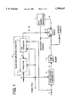
- FIG. 1 is an exemplary block diagram of the carrier synchronization unit which combines RLS phase and amplitude estimation with prediction in a decision-directed carrier synchronization architecture.
- FIG. 2 illustrates the frame structure of the transmission scheme.
- the transmitter periodically inserts known symbols, pilot symbols, which the carrier synchronization unit uses for training in a phase and amplitude estimation process;
- FIG. 3 is a detailed illustration of the phase & amplitude estimation process.
- the multiplicative distortion is calculated by using an RLS adaptive algorithm minimizing weighting square error between the receive signal and it's estimate.
- the estimate of the receive signal is formed by multiplying detected symbols and pilot symbols with multiplicative distortion estimates. Intersymbol interference free reception is assumed.
- FIG. 4 illustrates the calculation method for the prediction process.
- the prediction is based on Morrison's least-square fading-memory prediction algorithm, and the predictor uses current and past multiplicative distortion estimates to predict the multiplicative distortion in the future.
- FIG. 1 illustrates an exemplary block diagram of the decision-directed carrier synchronization unit, which combines RLS phase and amplitude estimation and prediction for carrier recovery.
- the complex-valued baseband linearly modulated received signal il, is used to estimate multiplicative distortion due to fading.
- the in-phase and quadrature (referred to as I/Q, hereinafter) components of the fading multiplicative distortion are lowpass processes and well suited for multiplicative distortion I/Q estimation.
- the low-pass property of the I/Q components of multiplicative distortion due to fading has been verified in many physical measurements for land-mobile communications and for aeronautical satellite communications.
- phase and amplitude estimation is performed by estimating the I/Q components of multiplicative distortion.
- the amplitude information, the magnitude of the complex multiplicative distortion, delivered by such a scheme could be used in fine automatic gain control (referred to as AGC, hereinafter) at no cost.
- AGC fine automatic gain control
- Diversity reception and maximal ratio combining can be easily implemented using this carrier synchronization unit, since this unit delivers the optimal estimates of channel gain.
- the transmitter periodically inserts known symbols, pilot symbols, which the receiver uses for training the phase and amplitude estimator 10.
- This frame structured transmission is illustrated in FIG. 2.
- the transmitter sends M pilot symbols, then N data symbols, then M new pilot symbols and so on. N/M ratios higher than 15 can be used, so the loss due to known symbol insertion can be neglected.
- These pilot symbols assist in recovery after the occurrence of phase errors by correcting phase and amplitude estimates during periods of training. Due to deep fades, or due to additive noise, phase reference jumps can occur, which can be corrected by using pilot symbol assistance. Correction leads to suppression of the error floor and enables multilevel modulation. However, no changes to the transmitted pulse shape or peak to average power ratio, so there is no increase in the complexity of the transmitter or receiver.
- the phase and amplitude estimator 10 derives phase and amplitude estimates from receive signal, il, using detected symbols, d1, or known pilot symbols, p1.
- Switch 6 selects detected symbols, d1, or known pilot symbols, p1, where frame synchronization is assumed, so the local pilot symbol generator 5 and control of the switch 6 are both synchronized with frame structured transmission.
- the phase and amplitude estimator 10 is the combination of a RLS phase and amplitude estimator 1 and predictor 2.
- the RLS phase and amplitude estimator 1 estimates multiplicative distortion, z1, by using an RLS adaptive algorithm.
- FIG. 3 is a more detailed illustration of the RLS phase and amplitude estimation process.
- Symbol sequence p1 -- d1 is formed by time multiplexing detected symbols, d1, and pilot symbols, p1.
- Symbol sequence p1 -- d1 and receive signal i1 are used as inputs for multiplicative distortion estimation z1.
- Multiplying symbols p1 -- d1 with the multiplicative distortion estimation z1, the estimation of receive signal, i3, is generated.
- the error signal e1 is calculated by subtracting receive signal estimate, i3, from receive signal, i1, as illustrated in FIG. 3.
- the RLS adaptive algorithm minimizes the time-average weighted squared error e1.
- the weight attached to any error e1 is reduced exponentially with the age of the error, so the algorithm minimizes: ##EQU1## where W is the weighting factor for the RLS adaptive algorithm.
- Using a higher weighting factor W for RLS estimation effectively introduces tracking delay in estimation z1. Correct symbol rate sampling timing and intersymbol-interference-free reception are assumed.
- the baseband receive signal, i1 is sampled once per symbol interval, at time instants ⁇ iT ⁇ , to give the samples ⁇ r1i ⁇ which are used by the RLS estimator 1 for multiplicative distortion estimation.
- the predictor 2 in FIG. 1 uses current and past multiplicative distortion estimates, z1, to predict the multiplicative distortion, z2, n symbols in the future.
- the prediction is based on Morrision's least-square fading memory prediction algorithm.
- the predictor 2 uses a sequence of estimates z1 i , the predictor 2 forms an n-step prediction z2 i+n ,i of multiplicative distortion.
- the predictor 2 must first determine the one-step prediction z2 i+1 ,i, by applying Morrision's degree-1 least-squares fading-memory prediction algorithm to estimates z1 i , z1 i-1 , z1 i-2 . . .
- the predictor 2 evaluates the following complex-values:
- the z2' i+1 ,i is an estimate of the difference between Z1 i+1 and z1 i and hence of the rate of change of z1 i with i.
- the algorithm assumes that z1 i -z1 i-1 is effectively invariant with i, over several adjacent values of i.
- Q is the prediction algorithm memory coefficient, a real-valued constant in the range 0 to 1 and usually close to 1.
- FIG. 4 illustrates the calculation using equation 1,2,3 and 4. This figure is a detailed the processing of predictor 2 in FIG. 1.
- the calculation for equation 1 is illustrated by subtractor 201.
- Blocks 202, 203 and 204 are used for the calculation of equation 2.
- Equation 3 is showed by blocks 205, 206, 207 and 208.
- the calculation for equation 4 is showed by blocks 209 and 210.
- the RLS estimator 1 in FIG. 1 sets internal memory values to zero, canceling in that way the impact of previous received samples on further estimates.
- restart of the RLS estimator process is done by internal memory reset at the beginning of each training interval. At the end of the training interval the restart of the prediction process should be done using the updated estimate for the preset, as specified by equations 5 and 6.
- the compensator 4 in FIG. 1 uses the estimated and predicted multiplicative distortion value, z2, for phase and amplitude compensation of the receive signal, i1.
- the compensator 4 multiplies receive signal, i1, by the complex value 1/z2.
- slicer 3 uses compensated signal, i2, slicer 3 makes a decision and outputs detected symbols, d1.
- Coherently detected symbols, d1, in a decision-directed synchronization strategy are used for phase and amplitude estimation of multiplicative distortion in the frequency nonselective fading channels. Assuming that the receiver is operating under reasonably low error rate conditions, detected symbols, dl, can be satisfactorily used for the process of multiplicative distortion estimation.
- Signals i1, i2, d1, p1, p1 -- d1, z1 and z2 are complex-valued signals with I/Q quadrature components. All processing is at the symbol rate. The sample of each signal in time instant iT, is noted by index i, where T is the symbol interval. All processing is at the symbol rate.
- the tracking delay effect can be reduced, which results in an improvement in BER performance.
- the proposed carrier recovery method minimizes the phenomenon of hang-up, with the possibility to extract channel quality information for the decoder. It is well suited for digital implementation, which meets the all digital realization requirements of a receiver in modern communication systems.
Landscapes
- Engineering & Computer Science (AREA)
- Computer Networks & Wireless Communication (AREA)
- Signal Processing (AREA)
- Digital Transmission Methods That Use Modulated Carrier Waves (AREA)
Abstract
The carrier synchronization unit combines the recursive least square (RLS) type phase and amplitude estimation and the prediction in a decision-directed carrier synchronization strategy. The fading channel multiplicative distortion is estimated using an adaptive recursive least square method which minimizes a time-weighted square error. Combining prediction based on a least-square fading memory curve fit and extrapolation with RLS estimation the tracking delay effect is reduced. Resulting in an improvement of receiver performance. The proposed method minimizes the phenomenon of hang-up allowing rapid phase acquisition with high probability of success.
Description
The present invention relates to cellular telephone systems. More particularly, the present invention relates to a novel method of carrier synchronization in a coherent detection data communications system over frequency nonselective fading channels.
Coherent detection schemes are superior compare to differentially coherent or noncoherent schemes in terms of power efficiency. However, carrier recovery, which is necessary for coherent detection, suffers from the time variant nature of fading channels. The power efficiency provided by coherent detection in digital communication systems is only possible when the receiver is supplemented by a carrier synchronization unit. Good estimates of the complex fading distortion are essential for successful synchronization.
Rapid fading is a central problem in digital mobile communications. Due to implementation considerations and the lack of a robust phase estimation algorithm, differentially coherent detection or other noncoherent techniques have historically been used in fading channels. Significant performance improvements can be achieved if near coherent demodulation is achieved. Linear modulation schemes such as M-PSK or M-QAM which employ coherent reception potentially form highly favorable communications schemes. The power advantage of coherent detection over noncoherent detection remains or is actually enhanced when channel coding or cochannel interference are considered. When the channel is corrupted by Rayleigh fading, resulting in rapidly varying channel phase, an efficient carrier synchronization technique which derives phase from the receive signal should be used in coherent demodulation schemes.
In the present invention, a novel and improved method for carrier synchronization is proposed. The proposed method combines RLS phase and amplitude estimation and prediction in a decision-directed carrier synchronization strategy. This method can be used for carrier synchronization in an open-loop architecture by employing a free-running oscillator to mix the received signal to baseband, avoiding the performance degradation of PLL during deep fades. This method minimizes the phenomenon of hang-up allowing rapid phase acquisition with high probability of success.
The weighting factor for the RLS adaptive algorithm should be close to 1 in order to reduce the effect of noise in the multiplicative distortion estimate. The higher the weighting factor, the smaller the effect of additive noise, but the slower the rate of response to changes in multiplicative distortion. The higher the weighting factor the less rapid the convergence of the RLS estimator, which effectively introduce tracking delay in estimation. This tracking delay is destructive in a decision-directed synchronization strategy and leads to burst errors.
When both components of complex-valued multiplicative distortion due to fading become small at the same time, they cause an amplitude deep and a large phase change. Such rapid phase variations cause difficulties for phase tracking systems such as a decision-directed synchronization system. Tracking delay in this case causes symbol decision errors and using these erroneous symbols for estimation further degrades estimation, which leads to phase errors and hang-up of the synchronization unit.
In the present invention, a novel and improved method to reduce the RLS estimation tracking delay effect is proposed. The reduction in tracking delay results in an improvement in receiver performance.
Combining prediction, which is based on a least-squares fading memory curve fit and extrapolation, with RLS estimation, the tracking delay effect can be reduced, which results in an improvement of BER receiver performance. The predictor uses the current and past multiplicative distortion estimates to predict multiplicative distortion n symbols in the future. Using a high weighting factor in the RLS adaptive algorithm, the effect of noise in multiplicative distortion estimates can be greatly reduced. These noiseless estimates are used for prediction, so the noise enhancement in the prediction process isn't so high and can be neglected.
The tracking delay problem has been overcame by incorporating a fading-memory prediction scheme, which results in an improvement of carrier tracking capability and overall receiver performance.
Coherent detection in frequency-flat fading channels has advantages over noncoherent detection when the issue of power efficiency is considered.
However, carrier recovery, which is necessary for coherent detection, suffers from the time-variant nature of fading channels.
In the present invention a novel and improved method for carrier synchronization is proposed. The proposed method combines RLS phase and amplitude estimation with prediction in a decision-directed carrier synchronization architecture. Combining RLS phase and amplitude estimation with prediction, the tracking delay problem has been overcome, resulting in an improvement in carrier tracking capability and overall BER receiver performance.
The feature and advantages of the present invention will become more apparent from the detailed description set forth below. Here is the brief description of the drawings.
FIG. 1 is an exemplary block diagram of the carrier synchronization unit which combines RLS phase and amplitude estimation with prediction in a decision-directed carrier synchronization architecture.
FIG. 2 illustrates the frame structure of the transmission scheme. The transmitter periodically inserts known symbols, pilot symbols, which the carrier synchronization unit uses for training in a phase and amplitude estimation process;
FIG. 3 is a detailed illustration of the phase & amplitude estimation process. The multiplicative distortion is calculated by using an RLS adaptive algorithm minimizing weighting square error between the receive signal and it's estimate. The estimate of the receive signal is formed by multiplying detected symbols and pilot symbols with multiplicative distortion estimates. Intersymbol interference free reception is assumed.
FIG. 4 illustrates the calculation method for the prediction process. The prediction is based on Morrison's least-square fading-memory prediction algorithm, and the predictor uses current and past multiplicative distortion estimates to predict the multiplicative distortion in the future.
FIG. 1 illustrates an exemplary block diagram of the decision-directed carrier synchronization unit, which combines RLS phase and amplitude estimation and prediction for carrier recovery. The complex-valued baseband linearly modulated received signal, il, is used to estimate multiplicative distortion due to fading. The in-phase and quadrature (referred to as I/Q, hereinafter) components of the fading multiplicative distortion are lowpass processes and well suited for multiplicative distortion I/Q estimation. The low-pass property of the I/Q components of multiplicative distortion due to fading has been verified in many physical measurements for land-mobile communications and for aeronautical satellite communications. In the proposed method, phase and amplitude estimation is performed by estimating the I/Q components of multiplicative distortion. The amplitude information, the magnitude of the complex multiplicative distortion, delivered by such a scheme could be used in fine automatic gain control (referred to as AGC, hereinafter) at no cost. Diversity reception and maximal ratio combining can be easily implemented using this carrier synchronization unit, since this unit delivers the optimal estimates of channel gain.
The transmitter periodically inserts known symbols, pilot symbols, which the receiver uses for training the phase and amplitude estimator 10. This frame structured transmission is illustrated in FIG. 2. The transmitter sends M pilot symbols, then N data symbols, then M new pilot symbols and so on. N/M ratios higher than 15 can be used, so the loss due to known symbol insertion can be neglected. These pilot symbols assist in recovery after the occurrence of phase errors by correcting phase and amplitude estimates during periods of training. Due to deep fades, or due to additive noise, phase reference jumps can occur, which can be corrected by using pilot symbol assistance. Correction leads to suppression of the error floor and enables multilevel modulation. However, no changes to the transmitted pulse shape or peak to average power ratio, so there is no increase in the complexity of the transmitter or receiver.
Refer FIG. 1. The phase and amplitude estimator 10 derives phase and amplitude estimates from receive signal, il, using detected symbols, d1, or known pilot symbols, p1. Switch 6 selects detected symbols, d1, or known pilot symbols, p1, where frame synchronization is assumed, so the local pilot symbol generator 5 and control of the switch 6 are both synchronized with frame structured transmission. The phase and amplitude estimator 10 is the combination of a RLS phase and amplitude estimator 1 and predictor 2. The RLS phase and amplitude estimator 1 estimates multiplicative distortion, z1, by using an RLS adaptive algorithm.
FIG. 3 is a more detailed illustration of the RLS phase and amplitude estimation process. Symbol sequence p1-- d1 is formed by time multiplexing detected symbols, d1, and pilot symbols, p1. Symbol sequence p1-- d1 and receive signal i1, are used as inputs for multiplicative distortion estimation z1. Multiplying symbols p1-- d1 with the multiplicative distortion estimation z1, the estimation of receive signal, i3, is generated. The error signal e1 is calculated by subtracting receive signal estimate, i3, from receive signal, i1, as illustrated in FIG. 3. The RLS adaptive algorithm minimizes the time-average weighted squared error e1. The weight attached to any error e1 is reduced exponentially with the age of the error, so the algorithm minimizes: ##EQU1## where W is the weighting factor for the RLS adaptive algorithm.
The higher the weighting factor W, the smaller the effect of additive noise on estimate z1, but the slower the rate of response of z1 to changes in multiplicative distortion. Using a higher weighting factor W for RLS estimation effectively introduces tracking delay in estimation z1. Correct symbol rate sampling timing and intersymbol-interference-free reception are assumed. The baseband receive signal, i1, is sampled once per symbol interval, at time instants {iT}, to give the samples {r1i} which are used by the RLS estimator 1 for multiplicative distortion estimation. The RLS estimator 1 outputs a sequence of complex valued estimates z1i, at time t=iT, where T is the symbol interval.
The predictor 2 in FIG. 1 uses current and past multiplicative distortion estimates, z1, to predict the multiplicative distortion, z2, n symbols in the future. The prediction is based on Morrision's least-square fading memory prediction algorithm.
Using a sequence of estimates z1i, the predictor 2 forms an n-step prediction z2i+n,i of multiplicative distortion. To form n-step prediction z2i+n,i the predictor 2 must first determine the one-step prediction z2i+1,i, by applying Morrision's degree-1 least-squares fading-memory prediction algorithm to estimates z1i, z1i-1, z1i-2. . . The predictor 2 evaluates the following complex-values:
d.sub.i =z1.sub.i -z2.sub.i, i-1 (1)
z2'.sub.i+1,i =z2'.sub.i,i-1 +(1-Q).sup.2 d.sub.i (2)
z2.sub.i+1,i =z2.sub.i,i-1 +z2'.sub.i+1,i +(1-Q.sup.2) d.sub.i(3)
z2.sub.i+n,i =z2.sub.i+1,i +(n-1)z2'.sub.i+1,i (4)
The z2'i+1,i is an estimate of the difference between Z1i+1 and z1i and hence of the rate of change of z1i with i. The algorithm assumes that z1i -z1i-1 is effectively invariant with i, over several adjacent values of i. Q is the prediction algorithm memory coefficient, a real-valued constant in the range 0 to 1 and usually close to 1.
FIG. 4 illustrates the calculation using equation 1,2,3 and 4. This figure is a detailed the processing of predictor 2 in FIG. 1. The calculation for equation 1 is illustrated by subtractor 201. Blocks 202, 203 and 204 are used for the calculation of equation 2. Equation 3 is showed by blocks 205, 206, 207 and 208. Finally, the calculation for equation 4 is showed by blocks 209 and 210. To start the process of prediction at the first received sample z11, the predictor sets:
z2.sub.1,0 =z1.sub.0, z2'.sub.1,0 =0 (5)
To restart the process of prediction at the time kT the predictor sets:
z2.sub.k,k-1 =z1.sub.k-1, z2'.sub.k,k-1 =0 (6)
To restart the process of RLS estimation, the RLS estimator 1 in FIG. 1 sets internal memory values to zero, canceling in that way the impact of previous received samples on further estimates.
Deep fades and noise cause differences between real multiplicative distortion and it's estimate which introduce the decision errors. These errors in a decision-directed carrier synchronization strategy affect the estimation which could lead to hang-up of the synchronization unit. To overcome these shortcomings the known pilot symbols are used for training the phase and amplitude estimator as illustrated in FIG. 2. During the training intervals the synchronization unit recovers from hang-up and starts correct estimation. In order to minimize the loss due to inserted pilot symbols only several pilot symbols are used per training interval. When a high RLS weighting factor is used in order to suppress the noise in estimates, the recovery from hang-up and estimation correction can not be done during training intervals, due to the high impact of previous samples to the RLS estimation. To speed-up the process of estimation during training intervals, restart of the RLS estimator process is done by internal memory reset at the beginning of each training interval. At the end of the training interval the restart of the prediction process should be done using the updated estimate for the preset, as specified by equations 5 and 6.
The compensator 4 in FIG. 1 uses the estimated and predicted multiplicative distortion value, z2, for phase and amplitude compensation of the receive signal, i1. The compensator 4 multiplies receive signal, i1, by the complex value 1/z2. Using compensated signal, i2, slicer 3 makes a decision and outputs detected symbols, d1. Coherently detected symbols, d1, in a decision-directed synchronization strategy are used for phase and amplitude estimation of multiplicative distortion in the frequency nonselective fading channels. Assuming that the receiver is operating under reasonably low error rate conditions, detected symbols, dl, can be satisfactorily used for the process of multiplicative distortion estimation. This symbol detection is needed here for the sake of multiplicative distortion estimation and does not necessarily to coincide with the actual detection process at the receiver. Signals i1, i2, d1, p1, p1-- d1, z1 and z2 are complex-valued signals with I/Q quadrature components. All processing is at the symbol rate. The sample of each signal in time instant iT, is noted by index i, where T is the symbol interval. All processing is at the symbol rate.
Combining prediction, which is based on a least-squares fading memory curve fit and extrapolation, with RLS estimation, the tracking delay effect can be reduced, which results in an improvement in BER performance. The proposed carrier recovery method minimizes the phenomenon of hang-up, with the possibility to extract channel quality information for the decoder. It is well suited for digital implementation, which meets the all digital realization requirements of a receiver in modern communication systems.
Claims (12)
1. The carrier synchronization unit comprising:
RLS phase and amplitude estimation means for estimating phase and amplitude of distortion due to fading based on RLS algorithm;
prediction means for predicting distortion n symbols (n is an integer) in the future, that is operatively cohering to said RLS phase and amplitude estimation means;
compensation means for compensating distortion of a received signal based on said estimated phase and amplitude of distortion;
detection means for coherently detecting data symbols based on compensated signal in said compensation means; and
means for periodically training said distortion estimation means.
2. The carrier synchronization unit of claim 1, wherein said RLS phase and amplitude estimation means comprises means for deriving phase and amplitude from said received signal in a decision-directed configuration by using an RLS adaptive algorithm that minimizes a time-average weighted squared error.
3. The carrier synchronization unit of claim 2, further comprising means for avoiding hang-up state in decision-directed process using pilot symbols for training indicated by known symbols periodically inserted.
4. The carrier synchronization unit of claim 2, wherein said RLS phase and amplitude estimation means comprises means for accelerating estimation process during said training intervals by setting internal memory of said RLS estimation means to zero canceling the effect of previous received samples on further estimation.
5. The carrier synchronization unit of claim 4 comprising:
means for generating pilot symbols during training intervals; and
multiplexing means for structuring frame multiplexing said pilot symbols and said detected symbols.
6. The carrier synchronization unit of claim 1, wherein said prediction means comprises means for predicting distortion n symbols (n is an integer) in the future using said current and past distortion values that is estimated by said phase and amplitude estimation means based on RLS algorithm wherein the prediction is based on Morrison's least-square fading-memory prediction algorithm.
7. The carrier synchronization unit of claim 5, wherein said prediction means comprises predicting distortion n steps in the future and compensating a tracking delay that is introduced by said RLS phase and amplitude estimation means.
8. The carrier synchronization unit of claim 5, further comprising means for restarting prediction process using updated estimation value during said training intervals.
9. The carrier synchronization unit of claim 2, wherein said compensation means comprises means for cohering to said RLS phase and amplitude estimation means and responsive for phase and amplitude compensation of received signal.
10. The carrier synchronization unit of claim 2, wherein said detection means for detecting symbols based on received signal that is phase and amplitude compensated, using phase and amplitude estimation of distortion in a decision-directed carrier synchronization.
11. A carrier synchronization method comprising the steps of:
estimating phase and amplitude distortion due to fading based on RLS algorithm;
predicting distortion n symbols (n is an integer) operatively cohering to the RLS estimated phase and amplitude distortion;
compensating distortion in a received signal due to fading based on the RLS estimated phase and amplitude distortion;
coherently detecting symbols in the compensated received signal.
12. The carrier synchronization method of claim 11, comprising ratios higher than fifteen for detected symbols and pilot symbols.
Applications Claiming Priority (2)
| Application Number | Priority Date | Filing Date | Title |
|---|---|---|---|
| JP7-246196 | 1995-09-25 | ||
| JP7246196A JP3024524B2 (en) | 1995-09-25 | 1995-09-25 | Carrier synchronization unit and synchronization method |
Publications (1)
| Publication Number | Publication Date |
|---|---|
| US5799047A true US5799047A (en) | 1998-08-25 |
Family
ID=17144945
Family Applications (1)
| Application Number | Title | Priority Date | Filing Date |
|---|---|---|---|
| US08/713,187 Expired - Fee Related US5799047A (en) | 1995-09-25 | 1996-09-12 | Carrier synchronization unit and synchronization method |
Country Status (2)
| Country | Link |
|---|---|
| US (1) | US5799047A (en) |
| JP (1) | JP3024524B2 (en) |
Cited By (25)
| Publication number | Priority date | Publication date | Assignee | Title |
|---|---|---|---|---|
| US6219391B1 (en) * | 1997-08-20 | 2001-04-17 | Matsushita Electric Industrial Co., Ltd. | Wireless communication apparatus and wireless communication method |
| US6249180B1 (en) * | 1999-09-08 | 2001-06-19 | Atmel Corporation | Phase noise and additive noise estimation in a QAM demodulator |
| US6314146B1 (en) * | 1998-06-05 | 2001-11-06 | The Board Of Trustees Of The Leland Stanford Junior University | Peak to average power ratio reduction |
| US20020057752A1 (en) * | 2000-06-23 | 2002-05-16 | Ntt Docomo, Inc. | Receive method and receiver in communication system |
| EP0959594A3 (en) * | 1998-05-22 | 2002-11-27 | Matsushita Electric Industrial Co., Ltd. | Weighted linear prediction, particularly for carrier recovery and channel estimation |
| US20020176520A1 (en) * | 2001-03-15 | 2002-11-28 | Chris Heegard | Phase-locked loop initialization via curve-fitting |
| US6504884B1 (en) * | 1999-05-12 | 2003-01-07 | Analog Devices, Inc. | Method for correcting DC offsets in a receiver |
| WO2003028205A1 (en) * | 2001-09-24 | 2003-04-03 | Atheros Communications, Inc. | Method and system to implement non-linear filtering and crossover detection for pilot carrier signal phase tracking |
| US6549583B2 (en) * | 2001-02-21 | 2003-04-15 | Magis Networks, Inc. | Optimum phase error metric for OFDM pilot tone tracking in wireless LAN |
| US6549561B2 (en) * | 2001-02-21 | 2003-04-15 | Magis Networks, Inc. | OFDM pilot tone tracking for wireless LAN |
| EP1313279A1 (en) * | 2001-11-14 | 2003-05-21 | Alcatel | Method for compensating phase impairments in a signal and corresponding receiver |
| US6606357B1 (en) | 1999-09-10 | 2003-08-12 | Harris Corporation | Carrier injecting waveform-based modulation scheme for reducing satellite transponder power requirements and earth terminal antenna size |
| US6628707B2 (en) | 2001-05-04 | 2003-09-30 | Radiant Networks Plc | Adaptive equalizer system for short burst modems and link hopping radio networks |
| US6633616B2 (en) * | 2001-02-21 | 2003-10-14 | Magis Networks, Inc. | OFDM pilot tone tracking for wireless LAN |
| US6654429B1 (en) | 1998-12-31 | 2003-11-25 | At&T Corp. | Pilot-aided channel estimation for OFDM in wireless systems |
| US20040157567A1 (en) * | 2003-02-10 | 2004-08-12 | Jittra Jootar | Weight prediction for closed-loop mode transmit diversity |
| US6801586B1 (en) * | 1999-08-31 | 2004-10-05 | Matsushita Electric Industrial Co., Ltd. | OFDM communication apparatus and propagation path estimation method |
| US20050013238A1 (en) * | 2003-07-18 | 2005-01-20 | Hansen Christopher J. | OFDM frame formatting |
| US20050118953A1 (en) * | 2002-04-11 | 2005-06-02 | Tobias Tynderfeldt | Diagonally layered multi-antenna transmission for frequency selective channels |
| US20050152404A1 (en) * | 1999-08-24 | 2005-07-14 | Paradyne Corporation | System and method for a robust preamble and transmission delimiting in a switched-carrier transceiver |
| US20050157821A1 (en) * | 2004-01-19 | 2005-07-21 | Kim Min-Ho | Apparatus and method for carrier acquisition of vestigial sideband (VSB) signal |
| US7079574B2 (en) | 2001-01-17 | 2006-07-18 | Radiant Networks Plc | Carrier phase recovery system for adaptive burst modems and link hopping radio networks |
| US7103116B2 (en) | 2001-09-24 | 2006-09-05 | Atheros Communications, Inc. | Detection of a false detection of a communication packet |
| US20070064840A1 (en) * | 2005-09-20 | 2007-03-22 | Insung Kang | Iterative channel prediction |
| US20090004989A1 (en) * | 2007-06-28 | 2009-01-01 | Kyungtae Han | Systems and methods for cross-platform radio frequency interference mitigation |
Families Citing this family (6)
| Publication number | Priority date | Publication date | Assignee | Title |
|---|---|---|---|---|
| US6356608B1 (en) | 1998-06-29 | 2002-03-12 | Telefonaktiebolaget Lm Ericsson (Publ) | Method, apparatus, and system for determining a location of a frequency synchronization signal |
| JP4918710B2 (en) * | 2000-08-23 | 2012-04-18 | 洋二 巻島 | SSB wireless communication system and radio |
| KR100425373B1 (en) * | 2001-12-05 | 2004-03-30 | 한국과학기술원 | Least Squares Frequency Estimation, Transmitter Diversity System and 3GPP System |
| KR100452619B1 (en) * | 2002-05-15 | 2004-10-13 | 한국과학기술원 | Estimation and compensaion method of I/Q mismatch and DC offset |
| JP4708105B2 (en) * | 2005-07-15 | 2011-06-22 | 日本無線株式会社 | Amplitude phase control device and receiving system |
| JP4827449B2 (en) * | 2005-07-15 | 2011-11-30 | 日本無線株式会社 | Amplitude phase control device and receiving system |
Citations (4)
| Publication number | Priority date | Publication date | Assignee | Title |
|---|---|---|---|---|
| US4899367A (en) * | 1988-02-02 | 1990-02-06 | Communications Research Laboratory Ministry Of Posts And Telecommunications | Multi-level quadrature amplitude modulator system with fading compensation means |
| US4947409A (en) * | 1987-11-27 | 1990-08-07 | Telefonaktiebolaget L M Ericsson | Apparatus for correcting frequency in a coherent receiver |
| US5513215A (en) * | 1993-09-20 | 1996-04-30 | Glenayre Electronics, Inc. | High speed simulcast data system using adaptive compensation |
| US5596608A (en) * | 1993-05-11 | 1997-01-21 | Hitachi Denshi Kabushiki Kaisha | Fading distortion compensation method and circuit |
-
1995
- 1995-09-25 JP JP7246196A patent/JP3024524B2/en not_active Expired - Fee Related
-
1996
- 1996-09-12 US US08/713,187 patent/US5799047A/en not_active Expired - Fee Related
Patent Citations (4)
| Publication number | Priority date | Publication date | Assignee | Title |
|---|---|---|---|---|
| US4947409A (en) * | 1987-11-27 | 1990-08-07 | Telefonaktiebolaget L M Ericsson | Apparatus for correcting frequency in a coherent receiver |
| US4899367A (en) * | 1988-02-02 | 1990-02-06 | Communications Research Laboratory Ministry Of Posts And Telecommunications | Multi-level quadrature amplitude modulator system with fading compensation means |
| US5596608A (en) * | 1993-05-11 | 1997-01-21 | Hitachi Denshi Kabushiki Kaisha | Fading distortion compensation method and circuit |
| US5513215A (en) * | 1993-09-20 | 1996-04-30 | Glenayre Electronics, Inc. | High speed simulcast data system using adaptive compensation |
Cited By (39)
| Publication number | Priority date | Publication date | Assignee | Title |
|---|---|---|---|---|
| US6219391B1 (en) * | 1997-08-20 | 2001-04-17 | Matsushita Electric Industrial Co., Ltd. | Wireless communication apparatus and wireless communication method |
| EP0959594A3 (en) * | 1998-05-22 | 2002-11-27 | Matsushita Electric Industrial Co., Ltd. | Weighted linear prediction, particularly for carrier recovery and channel estimation |
| US6314146B1 (en) * | 1998-06-05 | 2001-11-06 | The Board Of Trustees Of The Leland Stanford Junior University | Peak to average power ratio reduction |
| US6654429B1 (en) | 1998-12-31 | 2003-11-25 | At&T Corp. | Pilot-aided channel estimation for OFDM in wireless systems |
| US20040086055A1 (en) * | 1998-12-31 | 2004-05-06 | Ye Li | Pilot-aided channel estimation for OFDM in wireless systems |
| US7292651B2 (en) * | 1998-12-31 | 2007-11-06 | At&T Corp. | Pilot-aided channel estimation for OFDM in wireless systems |
| US6504884B1 (en) * | 1999-05-12 | 2003-01-07 | Analog Devices, Inc. | Method for correcting DC offsets in a receiver |
| US20050152404A1 (en) * | 1999-08-24 | 2005-07-14 | Paradyne Corporation | System and method for a robust preamble and transmission delimiting in a switched-carrier transceiver |
| US6801586B1 (en) * | 1999-08-31 | 2004-10-05 | Matsushita Electric Industrial Co., Ltd. | OFDM communication apparatus and propagation path estimation method |
| US6249180B1 (en) * | 1999-09-08 | 2001-06-19 | Atmel Corporation | Phase noise and additive noise estimation in a QAM demodulator |
| USRE39983E1 (en) | 1999-09-10 | 2008-01-01 | Harris Corporation | Carrier injecting waveform-based modulation scheme for reducing satellite transponder power requirements and earth terminal antenna size |
| US6606357B1 (en) | 1999-09-10 | 2003-08-12 | Harris Corporation | Carrier injecting waveform-based modulation scheme for reducing satellite transponder power requirements and earth terminal antenna size |
| US20020057752A1 (en) * | 2000-06-23 | 2002-05-16 | Ntt Docomo, Inc. | Receive method and receiver in communication system |
| US6987815B2 (en) | 2000-06-23 | 2006-01-17 | Ntt Docomo, Inc. | Receive method and receiver in communication system |
| US7079574B2 (en) | 2001-01-17 | 2006-07-18 | Radiant Networks Plc | Carrier phase recovery system for adaptive burst modems and link hopping radio networks |
| US6549561B2 (en) * | 2001-02-21 | 2003-04-15 | Magis Networks, Inc. | OFDM pilot tone tracking for wireless LAN |
| US7551677B2 (en) | 2001-02-21 | 2009-06-23 | Crawford James A | OFDM pilot tone tracking for wireless LAN |
| US6633616B2 (en) * | 2001-02-21 | 2003-10-14 | Magis Networks, Inc. | OFDM pilot tone tracking for wireless LAN |
| US6549583B2 (en) * | 2001-02-21 | 2003-04-15 | Magis Networks, Inc. | Optimum phase error metric for OFDM pilot tone tracking in wireless LAN |
| US6993095B2 (en) * | 2001-03-15 | 2006-01-31 | Texas Instruments Incorporated | Phase-locked loop initialization via curve-fitting |
| US20020176520A1 (en) * | 2001-03-15 | 2002-11-28 | Chris Heegard | Phase-locked loop initialization via curve-fitting |
| US6628707B2 (en) | 2001-05-04 | 2003-09-30 | Radiant Networks Plc | Adaptive equalizer system for short burst modems and link hopping radio networks |
| US7103116B2 (en) | 2001-09-24 | 2006-09-05 | Atheros Communications, Inc. | Detection of a false detection of a communication packet |
| US7203255B2 (en) | 2001-09-24 | 2007-04-10 | Atheros Communications, Inc. | Method and system to implement non-linear filtering and crossover detection for pilot carrier signal phase tracking |
| US20030112825A1 (en) * | 2001-09-24 | 2003-06-19 | Yi-Hsiu Wang | Method and system to implement non-linear filtering and crossover detection for pilot carrier signal phase tracking |
| US7184495B2 (en) | 2001-09-24 | 2007-02-27 | Atheros Communications, Inc. | Efficient pilot tracking method for OFDM receivers |
| WO2003028205A1 (en) * | 2001-09-24 | 2003-04-03 | Atheros Communications, Inc. | Method and system to implement non-linear filtering and crossover detection for pilot carrier signal phase tracking |
| EP1313279A1 (en) * | 2001-11-14 | 2003-05-21 | Alcatel | Method for compensating phase impairments in a signal and corresponding receiver |
| US7340018B2 (en) * | 2002-04-11 | 2008-03-04 | Telefonaktiebolaget Lm Ericsson (Publ) | Diagonally layered multi-antenna transmission for frequency selective channels |
| US20050118953A1 (en) * | 2002-04-11 | 2005-06-02 | Tobias Tynderfeldt | Diagonally layered multi-antenna transmission for frequency selective channels |
| US7155177B2 (en) * | 2003-02-10 | 2006-12-26 | Qualcomm Incorporated | Weight prediction for closed-loop mode transmit diversity |
| US20040157567A1 (en) * | 2003-02-10 | 2004-08-12 | Jittra Jootar | Weight prediction for closed-loop mode transmit diversity |
| US20050013238A1 (en) * | 2003-07-18 | 2005-01-20 | Hansen Christopher J. | OFDM frame formatting |
| US20050157821A1 (en) * | 2004-01-19 | 2005-07-21 | Kim Min-Ho | Apparatus and method for carrier acquisition of vestigial sideband (VSB) signal |
| US7570717B2 (en) | 2004-01-19 | 2009-08-04 | Samsung Electronics Co., Ltd. | Apparatus and method for pilot-less carrier acquisition of vestigial sideband (VSB) signal |
| US20070064840A1 (en) * | 2005-09-20 | 2007-03-22 | Insung Kang | Iterative channel prediction |
| US7706453B2 (en) * | 2005-09-20 | 2010-04-27 | Via Telecom Co., Ltd. | Iterative channel prediction |
| US20090004989A1 (en) * | 2007-06-28 | 2009-01-01 | Kyungtae Han | Systems and methods for cross-platform radio frequency interference mitigation |
| US8290439B2 (en) * | 2007-06-28 | 2012-10-16 | Intel Corporation | Systems and methods for cross-platform radio frequency interference mitigation |
Also Published As
| Publication number | Publication date |
|---|---|
| JP3024524B2 (en) | 2000-03-21 |
| JPH0993301A (en) | 1997-04-04 |
Similar Documents
| Publication | Publication Date | Title |
|---|---|---|
| US5799047A (en) | Carrier synchronization unit and synchronization method | |
| JP3013763B2 (en) | Carrier synchronization unit | |
| US5245611A (en) | Method and apparatus for providing carrier frequency offset compensation in a tdma communication system | |
| US5311545A (en) | Modem for fading digital channels affected by multipath | |
| EP0551081B1 (en) | Adaptive equalizer and receiver | |
| Aghamohammadi et al. | A new method for phase synchronization and automatic gain control of linearly modulated signals on frequency-flat fading channels | |
| US9148326B2 (en) | Turbo channel estimation for OFDM systems | |
| US5233632A (en) | Communication system receiver apparatus and method for fast carrier acquisition | |
| US5271042A (en) | Soft decision decoding with channel equalization | |
| JP3538187B2 (en) | OFDM receiver and data demodulation method in OFDM receiver | |
| US5434883A (en) | Adaptive equalizers | |
| US20050185743A1 (en) | Apparatus for burst and timing synchronization in high-rate indoor wireless communication | |
| JP3079950B2 (en) | Receiving apparatus and transmission method for orthogonal frequency division multiplex modulation signal | |
| KR20010006533A (en) | Method and apparatus for signal reception, and medium | |
| US20040071234A1 (en) | High rate receiver | |
| US5550868A (en) | π/4-DQPSK delay spread detection and compensation apparatus and method | |
| WO1997007620A1 (en) | Transmission system with improved symbol processing | |
| US6885693B1 (en) | Synchronization in digital data transmission systems | |
| US5497400A (en) | Decision feedback demodulator with phase and frequency estimation | |
| WO1993022861A1 (en) | Receiver for digital communication system | |
| KR20030093037A (en) | Burst mode receiver and method for receiving packet-based data stably on a telephone line | |
| JPH0969862A (en) | Digital radio communication receiver | |
| US5677934A (en) | Multipath propagation compensation in a TDMA system | |
| US6353913B2 (en) | Modulation detection method and apparatus | |
| US20020167999A1 (en) | Equalizer, receiver, and equalization method and reception method |
Legal Events
| Date | Code | Title | Description |
|---|---|---|---|
| AS | Assignment |
Owner name: NEC CORPORATION, JAPAN Free format text: ASSIGNMENT OF ASSIGNORS INTEREST;ASSIGNOR:DOBRICA, VASIC;REEL/FRAME:009465/0038 Effective date: 19960905 |
|
| FPAY | Fee payment |
Year of fee payment: 4 |
|
| FPAY | Fee payment |
Year of fee payment: 8 |
|
| REMI | Maintenance fee reminder mailed | ||
| LAPS | Lapse for failure to pay maintenance fees | ||
| STCH | Information on status: patent discontinuation |
Free format text: PATENT EXPIRED DUE TO NONPAYMENT OF MAINTENANCE FEES UNDER 37 CFR 1.362 |
|
| FP | Lapsed due to failure to pay maintenance fee |
Effective date: 20100825 |