US679751A - Clamp for holding buttons. - Google Patents
Clamp for holding buttons. Download PDFInfo
- Publication number
- US679751A US679751A US73622799A US1899736227A US679751A US 679751 A US679751 A US 679751A US 73622799 A US73622799 A US 73622799A US 1899736227 A US1899736227 A US 1899736227A US 679751 A US679751 A US 679751A
- Authority
- US
- United States
- Prior art keywords
- piece
- clamp
- plates
- buttons
- shank
- Prior art date
- Legal status (The legal status is an assumption and is not a legal conclusion. Google has not performed a legal analysis and makes no representation as to the accuracy of the status listed.)
- Expired - Lifetime
Links
- 238000009958 sewing Methods 0.000 description 3
- 230000001276 controlling effect Effects 0.000 description 2
- 239000004744 fabric Substances 0.000 description 2
- 241000272165 Charadriidae Species 0.000 description 1
- 229910000831 Steel Inorganic materials 0.000 description 1
- 229940000425 combination drug Drugs 0.000 description 1
- 230000000875 corresponding effect Effects 0.000 description 1
- 239000002184 metal Substances 0.000 description 1
- 239000010959 steel Substances 0.000 description 1
Images
Classifications
-
- D—TEXTILES; PAPER
- D05—SEWING; EMBROIDERING; TUFTING
- D05B—SEWING
- D05B3/00—Sewing apparatus or machines with mechanism for lateral movement of the needle or the work or both for making ornamental pattern seams, for sewing buttonholes, for reinforcing openings, or for fastening articles, e.g. buttons, by sewing
- D05B3/12—Sewing apparatus or machines with mechanism for lateral movement of the needle or the work or both for making ornamental pattern seams, for sewing buttonholes, for reinforcing openings, or for fastening articles, e.g. buttons, by sewing for fastening articles by sewing
- D05B3/14—Sewing apparatus or machines with mechanism for lateral movement of the needle or the work or both for making ornamental pattern seams, for sewing buttonholes, for reinforcing openings, or for fastening articles, e.g. buttons, by sewing for fastening articles by sewing perforated or press buttons
Definitions
- My improvement relates to clamps for buttons having holes extending through them and for holding and presenting such buttons in proper relation to the sewing mechanism of a machine by which they are to be attached to a fabric.
- the improvement comprises two plates, between-which the button is held, an intermediate piece having an inclined surface serving as bearings for the edge of a button, and means whereby said piece may be adjusted relatively to the said plates.
- These means may advantageously consist of a screw and nut, and combined with the nut may be an indicator to indicate the necessary adjustments for buttons of different sizes.
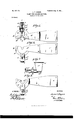
- Figure l is a plan or top view of a clamp embodying my improvement.
- Fig. 2 is an inverted plan or bottom view of the same.
- Fig. 3 is an inverted plan or bottom view with the bottom plate removed, and
- Fig. 4 is a transverse section at the plane of the dotted line 4 4 of Fig. 1.
- a A designate two plates, which may be conveniently made of semicircular outline, with a semicircular or analogous notch or opening at the center.
- the top plate A is made comparatively stiff and rigid and is pro vided with a shank a for attachment to any suitable part of a mechanism employed to hold or present a button to be sewed to the sewing mechanism which is to attach it to a fabric.
- the bottom plate A is resilient and has a tendency to move away from the upper plate, and any upward pressure upon the plate A or any downward pressure upon the plate A will produce a tendency in the two plates to move toward one another.
- the shank b is made integral, so that it cannot rotate or oscillate in the slot (L).
- the upper end of the shank b is provided with a head I), that overlaps the upper plate A.
- This head has a tapped hole with whichengages a screw 0, whose head 0 has a circumferential groove 0, with which engage lugs or", extend ing from the shank a of the plate A.
- the front of the piece B has two inclined surfaces 17 11 which are at such an angle to each other as to form for the edge of a button bearings which will centralize the button with reference to the central recesses of the plates A A thus securing the proper presentation of the button with reference to the'sewing mechanism of the sewing-machine.
- All the parts described may be made of metal, preferably of steel.
- An indicator may be employed for facilitating the adjustment of the piece B for different-sized buttons.
- Such an indicator may consist of a number of graduations marked upon the upper plate A, and an index, such as an arrow, marked upon the head I) of the shank b and belonging to the piece B.
- a stiff upper plate having an opening therein, a resilient lower plate, each of said plates having an open-ended slot and which slots register, a centering-piece intermediate of said upper and lower plates and having two oppositelyinclined surfaces forming bearings for a button, a shank provided for the centering-piece which projects through name to this specification in the presence of the opening in the upper plate, awscrew for two subscribing Witnesses. positively moving and controlling the position JAMES T H'OGAN of said centering-piece, a scale provided on 5 one of said plates, and an index carried by the witnesseses:
Landscapes
- Engineering & Computer Science (AREA)
- Textile Engineering (AREA)
- Sewing Machines And Sewing (AREA)
Description
No. 679,751. P atented Aug. 6, l90l. J. T. HOGAN. CLAMP HJB HOLDING BUTTONS.
(Application filed Nov. 8, 1899.)
(No Model.)
INVENTUR JamwZ/Ya a/n HIS ATTORNEY UNITED STATES PATENT OFFICE.
JAMES T. HOGAN, OF JERSEY CITY, NEW JERSEY, ASSIGNOR TO THE NATIONAL MACHINE 00., OF NEW YORK.
CLAMP FOR HOLDING BUTTONS.
SPECIFICATION forming part of Letters Patent No. 679,751, dated August 6, 1901. Application filed November 8, 1899. Serial No. 736.227. (No model.)
To alt whom, it may concern.-
Be it known that I, JAMES T. HOGAN, a citizen of the United States, residing at Jersey City, in the county of Hudson and State of New Jersey, have invented a new and useful Improvement in Clamps for Holding Buttons, of which the following is a specification.
My improvement relates to clamps for buttons having holes extending through them and for holding and presenting such buttons in proper relation to the sewing mechanism of a machine by which they are to be attached to a fabric.
The improvement comprises two plates, between-which the button is held, an intermediate piece having an inclined surface serving as bearings for the edge of a button, and means whereby said piece may be adjusted relatively to the said plates. These means may advantageously consist of a screw and nut, and combined with the nut may be an indicator to indicate the necessary adjustments for buttons of different sizes.
In the accompanying drawings, Figure l is a plan or top view of a clamp embodying my improvement. Fig. 2 is an inverted plan or bottom view of the same. Fig. 3 is an inverted plan or bottom view with the bottom plate removed, and Fig. 4 is a transverse section at the plane of the dotted line 4 4 of Fig. 1.
Similar letters of reference designate corre sponding parts in all the figures.
A A designate two plates, which may be conveniently made of semicircular outline, with a semicircular or analogous notch or opening at the center. The top plate A is made comparatively stiff and rigid and is pro vided with a shank a for attachment to any suitable part of a mechanism employed to hold or present a button to be sewed to the sewing mechanism which is to attach it to a fabric. The bottom plate A is resilient and has a tendency to move away from the upper plate, and any upward pressure upon the plate A or any downward pressure upon the plate A will produce a tendency in the two plates to move toward one another.
B designates a piece arranged intermediately of the plates A A It is provided with a shank b, that fits a slot of, formed in a shank a extendingfrom the upper plate A.
The shank b is made integral, so that it cannot rotate or oscillate in the slot (L The upper end of the shank b is provided with a head I), that overlaps the upper plate A. This head has a tapped hole with whichengages a screw 0, whose head 0 has a circumferential groove 0, with which engage lugs or", extend ing from the shank a of the plate A. By turning the screw in one direction the piece B may be moved forwardly or toward the central recess of the plates A A By turning the screw in a reverse direction the piece B will be moved in the reverse direction. The front of the piece B has two inclined surfaces 17 11 which are at such an angle to each other as to form for the edge of a button bearings which will centralize the button with reference to the central recesses of the plates A A thus securing the proper presentation of the button with reference to the'sewing mechanism of the sewing-machine.
All the parts described may be made of metal, preferably of steel. I
An indicator may be employed for facilitating the adjustment of the piece B for different-sized buttons. Such an indicator may consist of a number of graduations marked upon the upper plate A, and an index, such as an arrow, marked upon the head I) of the shank b and belonging to the piece B.
What I claim as new is 1. In a clamp for holding buttons, the com bination of a stilt upper plate having an opening therein, a resilient lower plate, each of said plates having an open-ended slot and which slots register, a centering-piece intermediate of said upper and lower plates having two oppositely-inclined surfaces forming bearings for a button, a shank provided for the centering-piece which projects through the opening in the upper plate, and a screw for positively moving and controlling the posit-ion of said centering-piece.
2. In a clamp for holding buttons, the combination of a stiff upper plate having an opening therein, a resilient lower plate, each of said plates having an open-ended slot and which slots register, a centering-piece intermediate of said upper and lower plates and having two oppositelyinclined surfaces forming bearings for a button, a shank provided for the centering-piece which projects through name to this specification in the presence of the opening in the upper plate, awscrew for two subscribing Witnesses. positively moving and controlling the position JAMES T H'OGAN of said centering-piece, a scale provided on 5 one of said plates, and an index carried by the Witnesses:
shank. GEO. E. CRUSE, In testimony whereof I have signed my J. M. RIEMANN.
Priority Applications (1)
| Application Number | Priority Date | Filing Date | Title |
|---|---|---|---|
| US73622799A US679751A (en) | 1899-11-08 | 1899-11-08 | Clamp for holding buttons. |
Applications Claiming Priority (1)
| Application Number | Priority Date | Filing Date | Title |
|---|---|---|---|
| US73622799A US679751A (en) | 1899-11-08 | 1899-11-08 | Clamp for holding buttons. |
Publications (1)
| Publication Number | Publication Date |
|---|---|
| US679751A true US679751A (en) | 1901-08-06 |
Family
ID=2748297
Family Applications (1)
| Application Number | Title | Priority Date | Filing Date |
|---|---|---|---|
| US73622799A Expired - Lifetime US679751A (en) | 1899-11-08 | 1899-11-08 | Clamp for holding buttons. |
Country Status (1)
| Country | Link |
|---|---|
| US (1) | US679751A (en) |
-
1899
- 1899-11-08 US US73622799A patent/US679751A/en not_active Expired - Lifetime
Similar Documents
| Publication | Publication Date | Title |
|---|---|---|
| US679751A (en) | Clamp for holding buttons. | |
| US313046A (en) | Machines | |
| US1048319A (en) | Saw-table guide. | |
| US653808A (en) | Button-clamp for sewing-machines. | |
| US1032017A (en) | Hook and eye clamp for sewing-machines. | |
| US1197400A (en) | Pantographic attachment for sewing-machines | |
| US154291A (en) | Improvement in sewing-machines | |
| US267563A (en) | mitchell | |
| US1231170A (en) | Sewing-machine ruffler. | |
| US699977A (en) | Narrow-ware loom. | |
| US625007A (en) | Soldering-pad | |
| US952087A (en) | Machine for sewing buttons to fabrics. | |
| US1116072A (en) | Buttonhole attachment for sewing-machines. | |
| US935794A (en) | Sewing-machine attachment. | |
| US995795A (en) | Sewing-machine gage. | |
| US1009266A (en) | Attachment-securing means. | |
| US507507A (en) | Vania | |
| US748290A (en) | Balance-escapement. | |
| US531098A (en) | Hat-lining machine | |
| US1249629A (en) | Cutter-setting indicator. | |
| US268930A (en) | Heebeet l | |
| US688310A (en) | Apparatus for locating foreign substances in bodies. | |
| US880364A (en) | Hat-holder. | |
| US496489A (en) | Island | |
| US794582A (en) | Chuck. |