US6779741B2 - Fuel injection apparatus for an internal combustion engine - Google Patents
Fuel injection apparatus for an internal combustion engine Download PDFInfo
- Publication number
- US6779741B2 US6779741B2 US10/290,508 US29050802A US6779741B2 US 6779741 B2 US6779741 B2 US 6779741B2 US 29050802 A US29050802 A US 29050802A US 6779741 B2 US6779741 B2 US 6779741B2
- Authority
- US
- United States
- Prior art keywords
- chamber
- control
- injection valve
- valve member
- fuel injection
- Prior art date
- Legal status (The legal status is an assumption and is not a legal conclusion. Google has not performed a legal analysis and makes no representation as to the accuracy of the status listed.)
- Expired - Fee Related, expires
Links
Images


Classifications
-
- F—MECHANICAL ENGINEERING; LIGHTING; HEATING; WEAPONS; BLASTING
- F02—COMBUSTION ENGINES; HOT-GAS OR COMBUSTION-PRODUCT ENGINE PLANTS
- F02M—SUPPLYING COMBUSTION ENGINES IN GENERAL WITH COMBUSTIBLE MIXTURES OR CONSTITUENTS THEREOF
- F02M61/00—Fuel-injectors not provided for in groups F02M39/00 - F02M57/00 or F02M67/00
- F02M61/16—Details not provided for in, or of interest apart from, the apparatus of groups F02M61/02 - F02M61/14
- F02M61/20—Closing valves mechanically, e.g. arrangements of springs or weights or permanent magnets; Damping of valve lift
- F02M61/205—Means specially adapted for varying the spring tension or assisting the spring force to close the injection-valve, e.g. with damping of valve lift
-
- F—MECHANICAL ENGINEERING; LIGHTING; HEATING; WEAPONS; BLASTING
- F02—COMBUSTION ENGINES; HOT-GAS OR COMBUSTION-PRODUCT ENGINE PLANTS
- F02M—SUPPLYING COMBUSTION ENGINES IN GENERAL WITH COMBUSTIBLE MIXTURES OR CONSTITUENTS THEREOF
- F02M45/00—Fuel-injection apparatus characterised by having a cyclic delivery of specific time/pressure or time/quantity relationship
- F02M45/02—Fuel-injection apparatus characterised by having a cyclic delivery of specific time/pressure or time/quantity relationship with each cyclic delivery being separated into two or more parts
- F02M45/04—Fuel-injection apparatus characterised by having a cyclic delivery of specific time/pressure or time/quantity relationship with each cyclic delivery being separated into two or more parts with a small initial part, e.g. initial part for partial load and initial and main part for full load
-
- F—MECHANICAL ENGINEERING; LIGHTING; HEATING; WEAPONS; BLASTING
- F02—COMBUSTION ENGINES; HOT-GAS OR COMBUSTION-PRODUCT ENGINE PLANTS
- F02M—SUPPLYING COMBUSTION ENGINES IN GENERAL WITH COMBUSTIBLE MIXTURES OR CONSTITUENTS THEREOF
- F02M45/00—Fuel-injection apparatus characterised by having a cyclic delivery of specific time/pressure or time/quantity relationship
- F02M45/12—Fuel-injection apparatus characterised by having a cyclic delivery of specific time/pressure or time/quantity relationship providing a continuous cyclic delivery with variable pressure
-
- F—MECHANICAL ENGINEERING; LIGHTING; HEATING; WEAPONS; BLASTING
- F02—COMBUSTION ENGINES; HOT-GAS OR COMBUSTION-PRODUCT ENGINE PLANTS
- F02M—SUPPLYING COMBUSTION ENGINES IN GENERAL WITH COMBUSTIBLE MIXTURES OR CONSTITUENTS THEREOF
- F02M47/00—Fuel-injection apparatus operated cyclically with fuel-injection valves actuated by fluid pressure
- F02M47/02—Fuel-injection apparatus operated cyclically with fuel-injection valves actuated by fluid pressure of accumulator-injector type, i.e. having fuel pressure of accumulator tending to open, and fuel pressure in other chamber tending to close, injection valves and having means for periodically releasing that closing pressure
- F02M47/027—Electrically actuated valves draining the chamber to release the closing pressure
-
- F—MECHANICAL ENGINEERING; LIGHTING; HEATING; WEAPONS; BLASTING
- F02—COMBUSTION ENGINES; HOT-GAS OR COMBUSTION-PRODUCT ENGINE PLANTS
- F02M—SUPPLYING COMBUSTION ENGINES IN GENERAL WITH COMBUSTIBLE MIXTURES OR CONSTITUENTS THEREOF
- F02M57/00—Fuel-injectors combined or associated with other devices
- F02M57/02—Injectors structurally combined with fuel-injection pumps
-
- F—MECHANICAL ENGINEERING; LIGHTING; HEATING; WEAPONS; BLASTING
- F02—COMBUSTION ENGINES; HOT-GAS OR COMBUSTION-PRODUCT ENGINE PLANTS
- F02M—SUPPLYING COMBUSTION ENGINES IN GENERAL WITH COMBUSTIBLE MIXTURES OR CONSTITUENTS THEREOF
- F02M59/00—Pumps specially adapted for fuel-injection and not provided for in groups F02M39/00 -F02M57/00, e.g. rotary cylinder-block type of pumps
- F02M59/20—Varying fuel delivery in quantity or timing
- F02M59/36—Varying fuel delivery in quantity or timing by variably-timed valves controlling fuel passages to pumping elements or overflow passages
- F02M59/366—Valves being actuated electrically
Definitions
- the invention is directed to an improved fuel injection apparatus for an internal combustion engine.
- a fuel injection apparatus of the type with which this invention is concerned is known from EP 0 987 431 A2.
- This fuel injection apparatus has a high-pressure fuel pump and a fuel injection valve connected to it for each cylinder of the internal combustion engine.
- the high-pressure fuel pump has a pump piston, which the engine sets into a stroke motion and which defines a pump working chamber.
- the fuel injection valve has a pressure chamber connected to the pump working chamber and an injection valve member, which controls at least one injection opening and which the pressure prevailing in the pressure chamber can move in the opening direction, counter to a closing force, in order to open the at least one injection opening.
- a first electrically actuated control valve is provided, which controls a connection between the pump working chamber and a relief chamber.
- a second electrically actuated control valve is also provided, which controls a connection between a control pressure chamber and a relief chamber.
- the pressure prevailing in the control pressure chamber acts on the injection valve member at least indirectly in a closing direction and the control pressure chamber is connected to the pump working chamber.
- the first control valve is closed and the second control valve is opened so that high pressure cannot build up in the control pressure chamber and the fuel injection valve can open.
- the second control valve is open, however, fuel drains out of the pump working chamber by means of the control pressure chamber, so that of the fuel quantity delivered by the pump piston, the fuel quantity available for injection is reduced and so is the pressure available for the injection.
- the efficiency of the fuel injection apparatus is less than optimal.
- the fuel injection apparatus has the advantage over the prior art that for the fuel injection, the second control valve can be closed so that no loss in fuel quantity and fuel pressure occurs during the injection, thus improving the efficiency of the fuel injection apparatus.
- the throttle restriction By means of the throttle restriction, when the second control valve is open, the outflow of fuel into the relief chamber results in a pressure loss in one of the partial chambers of the control pressure chamber so that the control piston and by means of it, the injection valve member, has a greater force exerted on it in the closing direction than when the second control valve is closed, i.e. when at least approximately the same pressure prevails in both partial chambers.
- FIG. 1 schematically depicts a fuel injection apparatus for an internal combustion engine according to the invention
- FIG. 2 shows an enlarged detail labeled II of the fuel injection apparatus shown in FIG. 1, and
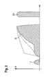
- FIG. 3 shows a march of pressure at injection openings of a fuel injection valve of the fuel injection apparatus.
- FIGS. 1 and 2 show a fuel injection apparatus for an internal combustion engine of a motor vehicle.
- the engine is preferably a compression-ignition engine.
- the fuel injection apparatus is preferably embodied as a so-called unit injector and for each cylinder of the engine, has a high-pressure fuel pump 10 and a fuel injection valve 12 connected to it, which form a combined component.
- the fuel injection apparatus can also be embodied as a so-called unit pump system in which the high-pressure fuel pump and the fuel injection valve of each cylinder are disposed separately from each other and are connected to each other by means of a line.
- the high-pressure fuel pump 10 has a pump body 14 with a cylinder bore 16 , in which a pump piston 18 is guided in a sealed fashion, which is driven at least indirectly by a cam 20 of a camshaft of the engine to execute a stroke motion counter to the force of a restoring spring 19 .
- the pump piston 18 defines a pump working chamber 22 in which fuel is compressed under high pressure during the delivery stroke of the pump piston 18 .
- the pump working chamber 22 is supplied with fuel from a fuel tank 24 of the motor vehicle.
- the fuel injection valve 12 has a valve body 26 , which is connected to the pump body 14 and can be comprised of several parts and in which an injection valve member 28 is guided so that it can move longitudinally in a bore 30 .
- the valve body 26 In its end region oriented toward the combustion chamber of the engine cylinder, the valve body 26 has at least one, preferably several, injection openings 32 .
- the injection valve member 28 In its end region oriented toward the combustion chamber, the injection valve member 28 has a for example approximately conical sealing surface 34 that cooperates with a valve seat 36 , which is embodied in the valve body 26 in its end region oriented toward the combustion chamber, and the injection openings 32 lead away from this seat or branch off downstream of it.
- annular chamber 38 In the valve body 26 , between the injection valve member 28 and the bore 30 toward the valve seat 36 , there is an annular chamber 38 , which in its end region oriented away from the valve seat 36 , transitions by means of a radial expansion of the bore 30 into a pressure chamber 40 that encompasses the injection valve member 28 .
- the injection valve member 28 At the level of the pressure chamber 40 , the injection valve member 28 has a pressure shoulder 42 produced by a cross sectional reduction.
- a prestressed closing spring 44 acts on the end of the injection valve member 28 oriented away from the combustion chamber and presses the injection valve member 28 toward the valve seat 36 .
- the closing spring 44 is disposed in a spring chamber 46 of the valve body 26 , which chamber adjoins the bore 30 .
- the end of the spring chamber 46 oriented away from the bore 30 in the valve body 26 is adjoined by another bore 48 , which has a control piston 50 guided in it in a sealed fashion, which is connected to the injection valve member 28 .
- the bore 48 constitutes a pressure control chamber 52 , which the control piston 50 divides into two separate partial chambers 54 , 56 that are sealed off from each other.
- the control piston 50 With its end face oriented toward the injection valve member 28 , the control piston 50 defines a first partial chamber 54 and with its end face oriented away from the injection valve member 28 , the control piston 50 defines a second partial chamber 56 in the control pressure chamber 52 .
- the control piston 50 is connected to the injection valve member 28 by means of a piston rod 51 whose diameter is smaller than that of the control piston 50 . Because of the piston rod 51 , the end surface area of the control piston 50 disposed in the first partial chamber 54 is somewhat smaller than the end surface area of the control piston 50 disposed in the second partial chamber 56 .
- the control pressure chamber 52 is sealed in relation to the spring chamber 46 .
- the two partial chambers 54 , 56 are connected to each other by means of a throttle restriction 55 , which is preferably disposed in the form of a bore in the control piston 50 , but can alternatively also be disposed in a bypass extending outside the control pressure chamber 52 .
- a conduit 60 leads from the pump working chamber 22 , through the pump body 14 , and the valve body 26 , to the pressure chamber 40 of the fuel injection valve 12 .
- a conduit 62 leads from the pump working chamber 22 or from the conduit 60 to the control pressure chamber 52 , which feeds into the second partial chamber 56 .
- the first partial chamber 54 of the control pressure chamber 52 is connected to a conduit 64 , which forms a connection to a relief chamber, which function can be at least indirectly fulfilled by the fuel tank 24 or another region in which a low pressure prevails.
- a connection 66 leads from the pump working chamber 22 or from the conduit 60 to a relief chamber 24 and this connection 66 is controlled by a first electrically actuated control valve 68 .
- the control valve 68 can be embodied as a 2/2-port directional-control valve or, as shown in FIG. 1, as a 2/3-port directional-control valve.
- the control valve 68 can be switched between three switched positions; the connection 66 is completely open in a first switched position, the connection 66 is open by means of a throttle restriction 67 in a second switched position, and the connection 66 is completely disconnected in a third switched position.
- the connection 64 of the control pressure chamber 52 to the relief chamber 24 is controlled by a second electrically actuated control valve 70 , which can be embodied as a 2/2-port directional-control valve.
- a throttle restriction 71 can be provided in the connection of the first partial chamber 54 of the control pressure chamber 52 to the relief chamber 24 .
- the control valves 68 , 70 can have an electromagnetic actuator or a piezoelectric actuator and are activated by an electronic control device 72 .
- FIG. 3 depicts the march of pressure p at the injection openings 32 of the fuel injection valve 12 over time t during an injection cycle.
- the pump is supplied with fuel from the fuel tank 24 .
- the fuel injection begins with a preinjection, in which the control device 72 brings the first control valve 68 into its second switched position or its third switched position so that the pump working chamber 22 is connected to the relief chamber 24 by means of the throttle restriction 67 ; the full high pressure according to the stroke motion of the pump piston 18 is not able to build up in the pump working chamber 22 in the second switched position, but is in fact able to build up in the third switched position.
- the control device 72 also closes the second control valve 70 .
- no fuel can flow out of the control pressure chamber 52 into the relief chamber 24 . Consequently, at least approximately the same pressure prevails in the two partial chambers 54 , 56 of the control pressure chamber 52 so that a resulting force acts on the control piston 50 in the closing direction of the injection valve member 28 since the surface area of the control piston 50 acted on by the pressure in the second partial chamber 56 is greater than its surface area acted on by the pressure in the first partial chamber 54 .
- This resulting compressive force on the control piston 50 acts in concert with the force of the closing spring 44 and acts on the injection valve member 28 by means of the piston rod 51 .
- the injection valve member 28 moves in the opening direction 29 and unblocks the at least one injection opening 32 .
- fuel only flows from the pump working chamber 22 into the pressure chamber 40 and via the throttle restriction 67 into the relief chamber 24 , but not via the control pressure chamber 52 into the relief chamber 24 .
- the preinjection corresponds to an injection phase labeled I in FIG. 3 .
- the control device brings the first control valve 68 into its first, completely open switched position and/or brings the second control valve 70 into its open switched position.
- the control device 72 closes the second control valve 70 .
- the invention can include the provision that the control device 72 initially brings the first control valve 68 into its second open position so that the connection 66 of the pump working chamber 22 to the relief chamber 24 via the throttle restriction 67 is open. The main injection then begins at a reduced pressure level, as depicted with a solid line in FIG. 3 .
- the control device 72 brings the first control valve 68 into its third, completely closed switched position so that the pump working chamber 22 is disconnected from the relief chamber 24 and the fuel injection takes place at a high pressure.
- the invention can also provide that the control device 72 already brings the first control valve 68 into its third, completely closed switched position at the beginning of the main injection so that the fuel injection takes place at a high pressure, as depicted with the dashed line in FIG. 3 .
- the control device 72 can already close the second control valve 70 at the beginning of the main injection. In this case, a march of pressure occurs, which is depicted with a dot-and-dash line in FIG. 3 .
- the control device 72 moves the second control valve 70 into its open switched position so that a greater force acts on the control piston 50 in the closing direction and the fuel injection valve 12 closes.
- the first control valve 68 remains in its third switched position.
- the control device 72 closes the second control valve 70 again so that a lower force acts on the control piston 50 in the closing direction and the fuel injection valve 12 opens.
- the secondary injection corresponds to an injection phase labeled III in FIG. 3 and occurs at a high pressure.
- the control device 72 brings the first control valve 68 into its first, completely open switched position and brings the second control valve 70 into its open switched position.
Landscapes
- Engineering & Computer Science (AREA)
- Chemical & Material Sciences (AREA)
- Combustion & Propulsion (AREA)
- Mechanical Engineering (AREA)
- General Engineering & Computer Science (AREA)
- Physics & Mathematics (AREA)
- Fluid Mechanics (AREA)
- Fuel-Injection Apparatus (AREA)
Applications Claiming Priority (3)
| Application Number | Priority Date | Filing Date | Title |
|---|---|---|---|
| DE10155406 | 2001-11-10 | ||
| DE10155406A DE10155406A1 (de) | 2001-11-10 | 2001-11-10 | Kraftstoffeinspritzeinrichtung für eine Brennkraftmaschine |
| DE10155406.0 | 2001-11-10 |
Publications (2)
| Publication Number | Publication Date |
|---|---|
| US20030111051A1 US20030111051A1 (en) | 2003-06-19 |
| US6779741B2 true US6779741B2 (en) | 2004-08-24 |
Family
ID=7705404
Family Applications (1)
| Application Number | Title | Priority Date | Filing Date |
|---|---|---|---|
| US10/290,508 Expired - Fee Related US6779741B2 (en) | 2001-11-10 | 2002-11-08 | Fuel injection apparatus for an internal combustion engine |
Country Status (3)
| Country | Link |
|---|---|
| US (1) | US6779741B2 (de) |
| EP (1) | EP1310668B1 (de) |
| DE (2) | DE10155406A1 (de) |
Cited By (3)
| Publication number | Priority date | Publication date | Assignee | Title |
|---|---|---|---|---|
| US20040123840A1 (en) * | 2001-12-07 | 2004-07-01 | Katja Matz | Fuel injection system for an internal combustion engine |
| US20050000493A1 (en) * | 2002-03-26 | 2005-01-06 | Volvo Lastvagnar Ab | Fuel injection system |
| US6976474B1 (en) * | 2004-07-19 | 2005-12-20 | Caterpillar Inc. | Mechanically actuated, electronically controlled fuel injection system |
Families Citing this family (4)
| Publication number | Priority date | Publication date | Assignee | Title |
|---|---|---|---|---|
| DE10160258A1 (de) * | 2001-12-07 | 2003-06-18 | Bosch Gmbh Robert | Kraftstoffeinspritzeinrichtung für eine Brennkraftmaschine |
| DE10358010B3 (de) * | 2003-12-11 | 2005-06-23 | Volkswagen Mechatronic Gmbh & Co. Kg | Pumpe-Düse-Vorrichtung |
| DE102004024926A1 (de) * | 2004-05-19 | 2005-12-15 | Volkswagen Mechatronic Gmbh & Co. Kg | Pumpe-Düse-Einheit |
| DE102013210036A1 (de) | 2013-05-29 | 2014-12-04 | Robert Bosch Gmbh | Hochdruckpumpe für ein Kraftstoffeinspritzsystem |
Citations (4)
| Publication number | Priority date | Publication date | Assignee | Title |
|---|---|---|---|---|
| US3469793A (en) * | 1967-05-11 | 1969-09-30 | Int Harvester Co | Fuel injection system |
| US4200231A (en) * | 1978-06-19 | 1980-04-29 | General Motors Corporation | Fuel injector nozzle |
| US6527198B1 (en) * | 1999-10-28 | 2003-03-04 | Robert Bosch Gmbh | Fuel injection valve for internal combustion engines |
| US6634336B1 (en) * | 1999-10-30 | 2003-10-21 | Robert Bosch Gmbh | Pressure booster and fuel injection system with a pressure booster |
Family Cites Families (6)
| Publication number | Priority date | Publication date | Assignee | Title |
|---|---|---|---|---|
| DE3767260D1 (de) * | 1986-09-25 | 1991-02-14 | Ganser Hydromag | Kraftstoffeinspritzventil. |
| GB9720003D0 (en) * | 1997-09-20 | 1997-11-19 | Lucas Ind Plc | Drive circuit |
| DE19826719A1 (de) * | 1998-06-16 | 1999-12-23 | Bosch Gmbh Robert | Ventilsteuereinheit für ein Kraftstoffeinspritzventil |
| GB9820237D0 (en) * | 1998-09-18 | 1998-11-11 | Lucas Ind Plc | Fuel injector |
| GB9920352D0 (en) * | 1999-08-28 | 1999-11-03 | Lucas Ind Plc | Fuel injector |
| GB9923823D0 (en) * | 1999-10-09 | 1999-12-08 | Lucas Industries Ltd | Fuel injector |
-
2001
- 2001-11-10 DE DE10155406A patent/DE10155406A1/de not_active Withdrawn
-
2002
- 2002-10-08 DE DE50208195T patent/DE50208195D1/de not_active Expired - Fee Related
- 2002-10-08 EP EP02022362A patent/EP1310668B1/de not_active Expired - Lifetime
- 2002-11-08 US US10/290,508 patent/US6779741B2/en not_active Expired - Fee Related
Patent Citations (4)
| Publication number | Priority date | Publication date | Assignee | Title |
|---|---|---|---|---|
| US3469793A (en) * | 1967-05-11 | 1969-09-30 | Int Harvester Co | Fuel injection system |
| US4200231A (en) * | 1978-06-19 | 1980-04-29 | General Motors Corporation | Fuel injector nozzle |
| US6527198B1 (en) * | 1999-10-28 | 2003-03-04 | Robert Bosch Gmbh | Fuel injection valve for internal combustion engines |
| US6634336B1 (en) * | 1999-10-30 | 2003-10-21 | Robert Bosch Gmbh | Pressure booster and fuel injection system with a pressure booster |
Cited By (5)
| Publication number | Priority date | Publication date | Assignee | Title |
|---|---|---|---|---|
| US20040123840A1 (en) * | 2001-12-07 | 2004-07-01 | Katja Matz | Fuel injection system for an internal combustion engine |
| US6976638B2 (en) * | 2001-12-07 | 2005-12-20 | Robert Bosch Gmbh | Fuel injection system for an internal combustion engine |
| US20050000493A1 (en) * | 2002-03-26 | 2005-01-06 | Volvo Lastvagnar Ab | Fuel injection system |
| US7191762B2 (en) * | 2002-03-26 | 2007-03-20 | Volvo Lastvagnar Ab | Fuel injection system |
| US6976474B1 (en) * | 2004-07-19 | 2005-12-20 | Caterpillar Inc. | Mechanically actuated, electronically controlled fuel injection system |
Also Published As
| Publication number | Publication date |
|---|---|
| EP1310668A2 (de) | 2003-05-14 |
| DE50208195D1 (de) | 2006-11-02 |
| US20030111051A1 (en) | 2003-06-19 |
| EP1310668A3 (de) | 2004-12-15 |
| DE10155406A1 (de) | 2003-05-22 |
| EP1310668B1 (de) | 2006-09-20 |
Similar Documents
| Publication | Publication Date | Title |
|---|---|---|
| US6892955B2 (en) | Fuel injection device for an internal combustion engine | |
| US7188782B2 (en) | Fuel injector provided with a servo leakage free valve | |
| US20040144364A1 (en) | Fuel injection system for an internal combustion engine | |
| US6779741B2 (en) | Fuel injection apparatus for an internal combustion engine | |
| US6981653B2 (en) | Fuel injection device for an internal combustion engine | |
| US6820594B2 (en) | Valve for controlling a communication in a high-pressure fluid system, in particular in a fuel injection system for an internal combustion engine | |
| US6659086B2 (en) | Fuel injection apparatus for internal combustion engines | |
| US6763809B2 (en) | Fuel injection apparatus for an internal combustion engine | |
| US6644281B2 (en) | Fuel injection apparatus for an internal combustion engine | |
| US6540160B2 (en) | Fuel injection device for an internal combustion engine | |
| US6651626B2 (en) | Fuel injection apparatus for internal combustion engines | |
| US20030101968A1 (en) | Fuel injection system for an internal combustion engine | |
| US6758417B2 (en) | Injector for a common rail fuel injection system, with shaping of the injection course | |
| US6953157B2 (en) | Fuel injection device for an internal combustion engine | |
| US6688289B2 (en) | Fuel injection system for internal combustion engines | |
| JP4253659B2 (ja) | 高圧液体システム、特に内燃機関のための燃料噴射装置の高圧液体システム内に設けられた接続部を制御するための弁 | |
| US6758414B2 (en) | Fuel injection device for an internal combustion engine | |
| US6976638B2 (en) | Fuel injection system for an internal combustion engine | |
| US20030098015A1 (en) | Fuel injection apparatus for an internal combustion engine | |
| US20030172910A1 (en) | Fuel injection system for an internal combustion engine | |
| US6637670B2 (en) | Fuel injection device for an internal combustion engine having a pressure-holding valve | |
| US20040182951A1 (en) | Fuel-injection device for an internal combustion engine | |
| US6688541B2 (en) | Fuel injection system for an internal combustion engine | |
| US7025284B2 (en) | Fuel injection system for an internal combustion engine | |
| US6912990B2 (en) | Fuel injection system for an internal combustion engine |
Legal Events
| Date | Code | Title | Description |
|---|---|---|---|
| AS | Assignment |
Owner name: ROBERT BOSCH GMBH, GERMANY Free format text: ASSIGNMENT OF ASSIGNORS INTEREST;ASSIGNOR:BOEHLAND, PETER;REEL/FRAME:013753/0753 Effective date: 20021125 |
|
| FPAY | Fee payment |
Year of fee payment: 4 |
|
| REMI | Maintenance fee reminder mailed | ||
| LAPS | Lapse for failure to pay maintenance fees | ||
| STCH | Information on status: patent discontinuation |
Free format text: PATENT EXPIRED DUE TO NONPAYMENT OF MAINTENANCE FEES UNDER 37 CFR 1.362 |
|
| FP | Expired due to failure to pay maintenance fee |
Effective date: 20120824 |