US6758564B2 - Line-scan laser ophthalmoscope - Google Patents
Line-scan laser ophthalmoscope Download PDFInfo
- Publication number
- US6758564B2 US6758564B2 US10/171,883 US17188302A US6758564B2 US 6758564 B2 US6758564 B2 US 6758564B2 US 17188302 A US17188302 A US 17188302A US 6758564 B2 US6758564 B2 US 6758564B2
- Authority
- US
- United States
- Prior art keywords
- light
- line
- eye
- incoming
- scanning
- Prior art date
- Legal status (The legal status is an assumption and is not a legal conclusion. Google has not performed a legal analysis and makes no representation as to the accuracy of the status listed.)
- Expired - Lifetime, expires
Links
- 230000003287 optical effect Effects 0.000 claims abstract description 65
- 210000001747 pupil Anatomy 0.000 claims abstract description 51
- 238000000034 method Methods 0.000 claims abstract description 17
- 238000004519 manufacturing process Methods 0.000 claims description 6
- 238000005259 measurement Methods 0.000 claims description 6
- 238000004458 analytical method Methods 0.000 claims description 4
- 238000003384 imaging method Methods 0.000 description 36
- 210000001525 retina Anatomy 0.000 description 20
- 230000006870 function Effects 0.000 description 14
- 238000005286 illumination Methods 0.000 description 12
- 230000010339 dilation Effects 0.000 description 10
- 230000008901 benefit Effects 0.000 description 7
- 210000004087 cornea Anatomy 0.000 description 7
- 230000000694 effects Effects 0.000 description 5
- XUIMIQQOPSSXEZ-UHFFFAOYSA-N Silicon Chemical compound [Si] XUIMIQQOPSSXEZ-UHFFFAOYSA-N 0.000 description 4
- 230000005540 biological transmission Effects 0.000 description 4
- 230000001427 coherent effect Effects 0.000 description 4
- 238000010586 diagram Methods 0.000 description 4
- 229910052710 silicon Inorganic materials 0.000 description 4
- 239000010703 silicon Substances 0.000 description 4
- 238000010521 absorption reaction Methods 0.000 description 3
- 206010064930 age-related macular degeneration Diseases 0.000 description 3
- 239000008280 blood Substances 0.000 description 3
- 210000004369 blood Anatomy 0.000 description 3
- 238000005516 engineering process Methods 0.000 description 3
- 230000000670 limiting effect Effects 0.000 description 3
- 208000002780 macular degeneration Diseases 0.000 description 3
- 230000002911 mydriatic effect Effects 0.000 description 3
- 230000002829 reductive effect Effects 0.000 description 3
- 230000011514 reflex Effects 0.000 description 3
- 230000002207 retinal effect Effects 0.000 description 3
- 239000000523 sample Substances 0.000 description 3
- 238000012216 screening Methods 0.000 description 3
- 230000035945 sensitivity Effects 0.000 description 3
- 238000000926 separation method Methods 0.000 description 3
- 238000003860 storage Methods 0.000 description 3
- 230000001360 synchronised effect Effects 0.000 description 3
- 206010012689 Diabetic retinopathy Diseases 0.000 description 2
- 206010019196 Head injury Diseases 0.000 description 2
- XUMBMVFBXHLACL-UHFFFAOYSA-N Melanin Chemical compound O=C1C(=O)C(C2=CNC3=C(C(C(=O)C4=C32)=O)C)=C2C4=CNC2=C1C XUMBMVFBXHLACL-UHFFFAOYSA-N 0.000 description 2
- 241001465754 Metazoa Species 0.000 description 2
- 230000004075 alteration Effects 0.000 description 2
- 238000003491 array Methods 0.000 description 2
- 238000004364 calculation method Methods 0.000 description 2
- 238000003745 diagnosis Methods 0.000 description 2
- 201000010099 disease Diseases 0.000 description 2
- 208000037265 diseases, disorders, signs and symptoms Diseases 0.000 description 2
- 239000003814 drug Substances 0.000 description 2
- 230000009977 dual effect Effects 0.000 description 2
- 239000000835 fiber Substances 0.000 description 2
- 238000009432 framing Methods 0.000 description 2
- 230000002452 interceptive effect Effects 0.000 description 2
- 238000002310 reflectometry Methods 0.000 description 2
- 230000002441 reversible effect Effects 0.000 description 2
- 239000000126 substance Substances 0.000 description 2
- 230000004304 visual acuity Effects 0.000 description 2
- 201000004569 Blindness Diseases 0.000 description 1
- 208000002177 Cataract Diseases 0.000 description 1
- 208000003569 Central serous chorioretinopathy Diseases 0.000 description 1
- 208000033379 Chorioretinopathy Diseases 0.000 description 1
- 206010027646 Miosis Diseases 0.000 description 1
- 206010034972 Photosensitivity reaction Diseases 0.000 description 1
- 208000029091 Refraction disease Diseases 0.000 description 1
- 206010038895 Retinal scar Diseases 0.000 description 1
- 230000004308 accommodation Effects 0.000 description 1
- 230000009471 action Effects 0.000 description 1
- 230000002411 adverse Effects 0.000 description 1
- 230000004430 ametropia Effects 0.000 description 1
- 238000002583 angiography Methods 0.000 description 1
- 230000002547 anomalous effect Effects 0.000 description 1
- 230000003466 anti-cipated effect Effects 0.000 description 1
- 210000001367 artery Anatomy 0.000 description 1
- 230000008033 biological extinction Effects 0.000 description 1
- 239000012472 biological sample Substances 0.000 description 1
- 230000001413 cellular effect Effects 0.000 description 1
- 238000006243 chemical reaction Methods 0.000 description 1
- 238000000576 coating method Methods 0.000 description 1
- 230000000295 complement effect Effects 0.000 description 1
- 238000010226 confocal imaging Methods 0.000 description 1
- 230000008602 contraction Effects 0.000 description 1
- 230000007547 defect Effects 0.000 description 1
- 238000013461 design Methods 0.000 description 1
- 230000001066 destructive effect Effects 0.000 description 1
- 238000001514 detection method Methods 0.000 description 1
- 238000002405 diagnostic procedure Methods 0.000 description 1
- 208000029436 dilated pupil Diseases 0.000 description 1
- 238000006073 displacement reaction Methods 0.000 description 1
- 238000009826 distribution Methods 0.000 description 1
- 238000013399 early diagnosis Methods 0.000 description 1
- 230000007705 epithelial mesenchymal transition Effects 0.000 description 1
- 238000011156 evaluation Methods 0.000 description 1
- 230000001815 facial effect Effects 0.000 description 1
- 238000002073 fluorescence micrograph Methods 0.000 description 1
- 230000036541 health Effects 0.000 description 1
- 230000006872 improvement Effects 0.000 description 1
- 238000007689 inspection Methods 0.000 description 1
- 230000010354 integration Effects 0.000 description 1
- 201000009941 intracranial hypertension Diseases 0.000 description 1
- 230000004298 light response Effects 0.000 description 1
- 239000000203 mixture Substances 0.000 description 1
- 238000012986 modification Methods 0.000 description 1
- 230000004048 modification Effects 0.000 description 1
- 230000003562 morphometric effect Effects 0.000 description 1
- 238000013425 morphometry Methods 0.000 description 1
- 210000004126 nerve fiber Anatomy 0.000 description 1
- 210000003733 optic disk Anatomy 0.000 description 1
- 239000013307 optical fiber Substances 0.000 description 1
- 238000005457 optimization Methods 0.000 description 1
- 230000007170 pathology Effects 0.000 description 1
- 230000000149 penetrating effect Effects 0.000 description 1
- 230000035515 penetration Effects 0.000 description 1
- 230000008447 perception Effects 0.000 description 1
- 208000007578 phototoxic dermatitis Diseases 0.000 description 1
- 231100000018 phototoxicity Toxicity 0.000 description 1
- 230000019612 pigmentation Effects 0.000 description 1
- 229920013655 poly(bisphenol-A sulfone) Polymers 0.000 description 1
- 230000008569 process Effects 0.000 description 1
- 238000012545 processing Methods 0.000 description 1
- 230000001681 protective effect Effects 0.000 description 1
- 230000001179 pupillary effect Effects 0.000 description 1
- 238000005295 random walk Methods 0.000 description 1
- 230000009467 reduction Effects 0.000 description 1
- 208000014733 refractive error Diseases 0.000 description 1
- 238000011160 research Methods 0.000 description 1
- 230000004044 response Effects 0.000 description 1
- 210000001927 retinal artery Anatomy 0.000 description 1
- 230000004256 retinal image Effects 0.000 description 1
- 230000004286 retinal pathology Effects 0.000 description 1
- 239000000790 retinal pigment Substances 0.000 description 1
- 210000001957 retinal vein Anatomy 0.000 description 1
- 239000004065 semiconductor Substances 0.000 description 1
- 238000004088 simulation Methods 0.000 description 1
- 239000007787 solid Substances 0.000 description 1
- 230000003595 spectral effect Effects 0.000 description 1
- 238000012360 testing method Methods 0.000 description 1
- 230000001225 therapeutic effect Effects 0.000 description 1
- 238000003325 tomography Methods 0.000 description 1
- 238000012546 transfer Methods 0.000 description 1
- 210000003462 vein Anatomy 0.000 description 1
- 230000000007 visual effect Effects 0.000 description 1
- 238000012800 visualization Methods 0.000 description 1
Images


Classifications
-
- A—HUMAN NECESSITIES
- A61—MEDICAL OR VETERINARY SCIENCE; HYGIENE
- A61B—DIAGNOSIS; SURGERY; IDENTIFICATION
- A61B3/00—Apparatus for testing the eyes; Instruments for examining the eyes
- A61B3/10—Objective types, i.e. instruments for examining the eyes independent of the patients' perceptions or reactions
- A61B3/1025—Objective types, i.e. instruments for examining the eyes independent of the patients' perceptions or reactions for confocal scanning
Definitions
- This invention relates generally to systems and methods for examining eyes. More particularly, the invention relates to systems and methods that employ scanned lines of light for examining eyes.
- Fundus imaging is the essential diagnostic procedure in ophthalmology. Instruments of the prior art that are useful for examining the fundus of the eye include direct and indirect ophthalmoscopes, the slit-lamp biomicroscope and the fundus camera. Complementary tools have been developed that broaden diagnostic and therapeutic possibilities, such as the Scanning Laser Ophthalmoscope (SLO).
- SLO Scanning Laser Ophthalmoscope
- the SLO is a superior tool for rapidly and continuously acquiring high-contrast images of the ocular fundus and its structures, including the distribution of choroidal blood, melanin, and retinal pigments. Because it accommodates a variety of visible and NIR wavelengths, the SLO is especially useful for the study and early diagnosis of diseases such as age-related macular degeneration (AMD) and diabetic retinopathy.
- AMD age-related macular degeneration
- the SLO is a powerful diagnostic tool for characterizing retinal pathologies, as well as for angiography, tomography, perimetry, and general psychophysics. Confocal SLO imaging is very effective in patients suffering from mild cataract, or from pathologies causing clouding of the vitreous.
- Another device for examining the fundus of the eye is the instrument described in U.S. Pat. No. 6,267,477, issued on Jul. 31, 2001 to Karpol et al. The Karpol instrument is described as operating on the principle of slit lamp bimicroscopy performed on an eye having a dilated pupil.
- the Karpol instrument uses a defined angle between a beam going to the retina and a beam returning from the retina, and there is a distance at the area of the pupil between the incident beam and the measured scattered beams.
- the Karpol instrument uses a two dimensional CCD camera as one of three cameras used to record images.
- the line-scanning laser ophthalmoscope (LSLO) of the invention has a significant confocal advantage in image clarity and contrast, and depth of penetration at the ocular fundus compared with conventional digital fundus photography.
- the LSLO has features not currently available in commercial SLOs, and is less expensive.
- the hand-held digital LSLO has proven that high quality, non-mydriatic (e.g., undilated pupil), line-confocal retinal images and stereo pairs can be obtained with a simple, compact design with fewer moving parts and components than current SLO systems.
- the system and method involves a monostatic beam geometry, e.g., the light incoming to the thing to be observed, and the light collected in reflection from the thing, pass through the same location in space between the thing and the optical component nearest the thing.
- a monostatic beam geometry e.g., the light incoming to the thing to be observed, and the light collected in reflection from the thing, pass through the same location in space between the thing and the optical component nearest the thing.
- Dilation is generally performed by applying chemicals topically and waiting for the dilation to occur. The waiting period can be some minutes, typically twenty minutes. Absence of a dilation requirement means that an instrument embodying principles of the invention can be used immediately, rather than only after a delay necessitated by the dilation of the pupil. This allows use in settings such as emergency or field use, where other instruments become useful only after the dilation of the pupil is complete. Dilation of the pupil causes the patient to have reduced visual acuity for periods of up to hours, until the effect of the dilation chemicals wears off. Dilation of the pupil can require a patient to use protective eyewear or to avoid light of ordinary intensity. Dilation of the pupil can cause a patient discomfort. The use of an instrument embodying principles of the invention can eliminate all of the above negative features of dilation of the pupil.
- the inventive technology provides an affordable clinical instrument that gives the clinician the power and resolution of the SLO, with some operational features of the most familiar ophthalmic diagnostic instruments, in an untethered package that is comparable in size and weight to commercial hand-held digital video cameras.
- the LSLO can provide stereo fundus images.
- a binocular LSLO with low-cost wearable display technology and more deeply penetrating near-infrared (NIR) light, can provide real time 3-D morphometric information that is usually the domain of slit-lamp biomicroscopes, binocular indirect ophthalmoscopes (BIOs), and stereo fundus photography at shorter wavelengths.
- NIR operation increases patient comfort and reduces the risk of phototoxicity during extended exams or procedures.
- color information can be captured and fused with NIR images.
- the digital LSLO allows the operator to switch views between live-motion and captured still images with the touch of a button.
- Synchronous modulation of laser illumination with line-by-line image acquisition and variable scans allows stereo images, dual-color images, or fluorescence images to be multiplexed and recorded.
- the LSLO can be quickly reconfigured for anterior segment imaging, pupil size and light response.
- the compact and lightweight LSLO offers the potential for use as a hand-held emergency care aid, particularly with blood in the vitreous from eye or head trauma.
- a portable digital LSLO which performs some of these functions at a cost approaching indirect ophthalmoscopes, while retaining much of the confocal and NIR advantages of the SLO, becomes more clinically versatile and commercially attractive.
- the invention relates to a line-scanning laser ophthalmoscope (LSLO).
- the LSLO comprises a light source providing a substantially point source of light; an optical apparatus and a one-dimensional detector.
- the optical apparatus comprises an optical component that accepts the light from the laser and provides a line of incoming light, at least one optical component that (i) scans a portion of an eye with the incoming line of light in a direction perpendicular to the line, (ii) confocally receives reflected light from the illuminated portion of the eye, and (iii) provides output light in a line focus configuration; and a turning mirror that redirects a selected one of the incoming light and the reflected light.
- the one-dimensional detector detects the output light and provides an electrical signal responsive to the output light at each of a plurality of locations along the line of output light.
- the light source providing a substantially point source of light comprises a laser.
- the light source providing a substantially point source of light comprises a super-luminescent diode.
- the optical component that accepts the light from the light source and provides a line of light comprises one or more lenses.
- the optical component that accepts the light from the light source and provides a line of light comprises a holographic optical element.
- the LSLO further comprises a signal analysis module that decodes electrical signals from the one-dimensional detector and that generates an array of data representative of reflected light from the illuminated portion of the eye.
- the LSLO further comprises a display module that displays information representative of the array of data generated by the signal analysis module.
- the one-dimensional detector is a linear CCD array or a linear CMOS array in some embodiments.
- the laser is an infrared laser.
- the infrared laser operates at a wavelength in the range of 700 nm to 950 nm.
- the infrared laser operates at a wavelength of substantially 830 nm.
- the optical apparatus of he LSLO further comprises a scanning mirror that provides a scanned line of light having a scan direction perpendicular to the line of light, one or more lenses that focus the scanned line of light on a portion of an eye, one or more lenses that confocally receive reflected light from the illuminated portion of the eye and provide a line of reflected light, a scanning mirror that redirects the line of reflected light, a pupil stop that prevents unwanted light from proceeding through the optical apparatus, and an objective lens that focuses the redirected line of reflected light onto the one-dimensional detector.
- the scanning mirror that intercepts the redirected line of light and provides a scanned line of light and the scanning mirror that redirects the line of reflected light are the same scanning mirror.
- the one or more lenses that focus the scanned line of light on a portion of an eye and the one or more lenses that confocally receive reflected light from the illuminated portion of the eye are the same one or more lenses.
- the pupil stop prevents non-confocally received light from proceeding through the optical apparatus.
- the invention features a line-scanning ophthalmoscope.
- the line-scanning ophthalmoscope comprises a light source providing a substantially point source of light, an optical apparatus and a one-dimensional detector.
- the optical apparatus receives light from the light source, (ii) scans a portion of an eye with the line of light in a direction perpendicular to the line, (iii) confocally receives reflected light from the illuminated portion of the eye, and (iv) provides output light in a line focus configuration.
- the one-dimensional detector detects the output light and provides an electrical signal responsive to the output light at each of a plurality of locations along the line of output light.
- the invention relates to a line-scanning laser ophthalmoscope (LSLO).
- the LSLO comprises a light source providing a substantially point source of light; an optical apparatus and a one-dimensional detector.
- the optical apparatus comprises an optical component that accepts the light from the laser and provides a line of incoming light, at least one optical component that (i) scans a portion of an eye having an undilated pupil with the incoming line of light in a direction perpendicular to the line, (ii) confocally receives reflected light from the illuminated portion of the eye, and (iii) provides output light in a line focus configuration, and a turning mirror that redirects a selected one of the incoming light and the reflected light.
- the one-dimensional detector detects the output light and provides an electrical signal responsive to the output light at each of a plurality of locations along the line of output light.
- the invention relates to a line-scanning laser ophthalmoscope (LSLO).
- the LSLO comprises a light source providing a substantially point source of light; an optical apparatus and a one-dimensional detector.
- the optical apparatus comprises an optical component that accepts the light from the laser and provides a line of incoming light, at least one optical component that (i) scans a portion of an eye with the incoming line of light in a direction perpendicular to the line, (ii) confocally receives reflected light from the illuminated portion of the eye, the incoming line of light and the reflected light having monostatic beam geometry, and (iii) provides output light in a line focus configuration, and a turning mirror that redirects a selected one of the incoming light and the reflected light.
- the one-dimensional detector detects the output light and provides an electrical signal responsive to the output light at each of a plurality of locations along the line of output light.
- the invention in a further aspect relates to a method of making a optical measurement of an object.
- the method includes the steps of providing an incoming line of light, scanning a portion of an object with the incoming line of light in a direction perpendicular to the line, confocally receiving reflected light from the illuminated portion of the object, providing output light in a line focus configuration from the received reflected light, separating the incoming light and the output light, detecting the output light, and providing an electrical signal responsive to the output light at each of a plurality of locations along the line of output light.
- the object is an eye.
- the method further comprises the steps of decoding the electrical signal, and generating an array of data representative of reflected light from the illuminated portion of the object.
- the invention includes a method of making an ophthalmoscopic measurement.
- the method includes the steps of providing an incoming line of light, scanning a portion of an eye having an undilated pupil with the incoming line of light in a direction perpendicular to the line, confocally receiving reflected light from the illuminated portion of the eye, providing output light in a line focus configuration from the received reflected light, separating the incoming light and the output light, detecting the output light, and providing an electrical signal responsive to the output light at each of a plurality of locations along the line of output light.
- the invention in yet an additional aspect, relates to a method of making an ophthalmoscopic measurement.
- the method includes the steps of providing an incoming line of light, scanning a portion of an eye with the incoming line of light in a direction perpendicular to the line, and confocally receiving reflected light from the illuminated portion of the eye, using a monostatic beam geometry for the incoming line of light and the reflected light.
- the method also includes the steps of providing output light in a line focus configuration from the received reflected light, separating the incoming light and the output light, detecting the output light, and providing an electrical signal responsive to the output light at each of a plurality of locations along the line of output light.
- FIG. 1 is a schematic diagram showing an embodiment of a line scanning imaging system, according to principles of the invention
- FIG. 2A is a side view of the optical layout of an illustrative line-scanning laser ophthalmoscope that embodies principles of the invention
- FIG. 2B is a top view of the optical layout of the illustrative line-scanning laser ophthalmoscope that is depicted in FIG. 2A;
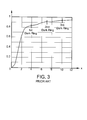
- FIG. 3 is a diagram showing the integrated power falling within a circle of a given radius, according to the prior art
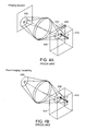
- FIG. 4A illustrates the optical effect of defocusing in a prior art full field imaging method
- FIG. 4B shows the optical effect of defocusing in a confocal “flying spot” system of the prior art
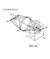
- FIG. 4C illustrates the optical effect of defocusing in a line scanning imaging system such as the LSLO of the invention
- FIGS. 5A and 5B show the standard prior art United States Air Force (USAF) resolution target #51 at low and high magnification, respectively;
- FIGS. 6A and 6B show prior art target images that appear on the reverse of a United States one dollar bill
- FIGS. 7A and 7B show forty degree field LSLO images in the left and right eyes of a human subject, respectively, according to principles of the invention
- FIG. 8 shows a standard SLO image of the prior art
- FIGS. 9A and 9B show twenty degree field LSLO images in a human subject, according to principles of the invention.
- FIGS. 10A and 10B shows illustrative disc image pairs captured in succession with the LSLO, according to principles of the invention
- FIG. 11 is an image that illustrates confocal and anterior segment imaging, according to principles of the invention.
- the digital LSLO instrument can be used as a relatively inexpensive multi-mode screening tool to facilitate rapid, non-mydriatic exams for large numbers of patients.
- rapid is to be understood as connoting real time operation.
- the instrument aids in the early detection of AMD, and other diseases of the elderly, where no economical early warning methods currently exist.
- the digital LSLO complements existing diagnostics and tele-medicine screening tools for detecting onset of diabetic retinopathy. Many elderly patients may have difficulty in adapting their posture to the demands of any of the standard instruments. Pediatric examination has similar constraints. Instead, instruments should adapt to the needs of the patient.
- the compact and lightweight LSLO may be used as a hand-held primary care and emergency care aid.
- the LSLO according to principles of the invention is advantageously used without the necessity to dilate a pupil of an eye, and employs a monostatic beam geometry.
- simplified versions of the LSLO may be used by EMTs for head trauma where anomalous bulging of the optic disk is indicative of elevated intracranial pressure, or with blood in the vitreous, as well as for stereo examination of the anterior segment and recording of pupil size and response.
- High-quality images of injured ocular structures can be captured in a fraction of a second, and transmitted to a treatment center for diagnosis and advice.
- Veterinary applications include animal certification and identification.
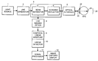
- FIG. 1 an embodiment of a line scanning imaging system is shown in schematic form.
- FIG. 1 can also be viewed as a schematic diagram showing the steps of a process, such as a method of use of the imaging system, in which each step is represented by a box in the diagram.
- a light source 1 which in some embodiments is a laser or a super-luminescent diode, provides a substantially point source of light.
- the light is infrared light. In other embodiments, light within the spectral range from the ultraviolet through the infrared may be provided.
- the light is received in a line generator 2 and is converted to a line of light.
- the line generator 2 is one or more lenses, or a holographic optical element.
- the line of light from the line generator 2 impinges on a beam conditioner 5 that includes a beam separator 3 and a scanning reflector 4 .
- the line of light interacts with the beam separator 3 and the scanning reflector 4 in either of two sequences.
- the line of light interacts with the beam separator 3 before reaching the scanning reflector 4 , for example in an embodiment in which the beam separator is a turning mirror or turning prism that intercepts the line of light as it travels in what will be referred to as the incoming direction, e.g., the direction of travel toward the object to be examined or imaged.
- the beam separator 3 is a turning mirror or turning prism that receives returning light that has been reflected from the object to be examined or imaged.
- the beam separator 3 and the scanning reflector 4 are configured to oblige the incoming light and the returning light to follow separate paths, respectively, between the light source and the beam conditioner 5 , and between the beam conditioner 5 and the linear detector 10 (which will be further described below).
- An optical interface 6 such as one or more lenses receives a line of light that scans in a direction perpendicular to the line, and focuses the light on an adjacent object 7 to be examined.
- the object 7 is a human eye.
- the eye 7 includes a cornea 20 , a pupil 22 and a retina 24 .
- the eye 7 includes a region referred to generally as a fundus 26 , which is the interior rear wall of the eye 7 .
- the object 7 to be examined or imaged is a mammalian eye, or the object 7 is an object of interest that has optical attributes that are subject to examination by a scanned line of light.
- the incoming line of light is scanned across a portion of the object 7 such as the fundus 26 of the eye.
- light that impinges an object can be affected in three ways.
- the light can pass through the object in transmission, the light can be absorbed by the object and may also be re-emitted, and the light can be reflected by the object.
- an object of interest such as the eye 7
- there will be reflections from some regions of the eye 7 including the front surface of the cornea 20 , and the front surface of the fundus 26 .
- Some structures in the eye 7 will absorb and re-emit some of the light, such as layers from the front of the fundus 26 and below the fundus 26 .
- the transmission, absorption/re-emission, and reflection properties of different portions of the object 7 will in general be a function of the wavelength of the incoming light, and will also depend on the structure and composition of the regions of the object 7 .
- the light that returns to the line-scanning imaging apparatus from the object 7 is a light in the form of a line, which is the reflection and or the absorption and re-emission of the incoming line of light. It is also possible that extraneous light may enter the apparatus, for example as a consequence of operating the apparatus in an environment where ambient light is present.
- the returning light which for simplicity will be described as reflected light, is received confocally by the optical interface 6 .
- the returning light is reflected by the scanning reflector 4 in a synchronous manner with the scanning of the incoming line of light, so that the reflected light passes to the line imaging optics 8 .
- the line imaging optics 8 reconfigures the reflected light into a line.
- the line of reflected light passes a confocal linear aperture 9 and impinges on a linear detector 10 .
- the beam conditioner 5 is configured to position the beam separator 3 at the conjugate to the cornea 20 , and to position the scanning reflector 4 at the conjugate to the pupil 22 .
- the confocal linear aperture 9 is positioned to be conjugate to the line illumination on the retina 24 .
- the confocal linear aperture 9 can be designed to prevent light that is not confocally received by the apparatus from passing through to the linear detector 10 .
- the linear detector 10 is a linear CCD array detector, such as a 1 ⁇ 512 pixel linear array.
- the linear detector 10 is a 1 ⁇ N linear CMOS array, where N is an integer greater than 1 representing the number of pixels in the array.
- the electrical signals generated within the linear detector 10 pass to an electrical signal processor 11 , such as an analog-to-digital (A-to-D) converter that converts analog light levels to digital signals.
- the signal processor 11 is connected to a processing apparatus such as a commercially available personal computer that can receive, store, and analyze the electrical signals in digital form, for example by use of a frame grabber.
- the A-to-D and the computer are optionally connected to an image/capture/display module 12 , which can include any of a computer monitor or video display, a printer, a plotter, a machine-readable storage medium such as one or more of electronic, magnetic and optical storage media (e.g., memory chips, magnetic disks, CD-ROM, DVD), and an enunciator such as a speaker.
- the apparatus is portable, and the linear detector 10 and signal processor 11 apparatus are miniaturized and are provided on one or more semiconductor chips.
- power supplies and motors (which are not shown in FIG. 1) are provided to operate the scanning reflector 4 , the light source 1 , the linear detector 10 , and the signal processor 11 .
- the image capture/display 12 can in some embodiments be a small viewable electronic display, such as is found in a portable television, a cellular telephone, or a personal digital assistant.
- the image capture/display 12 is a remote display, for example a display situated in the office of a consulting specialist, who receives the image via a connection such as telephone, television, internet, satellite transmission, or optical fiber interconnection, and who examines the image and provides an opinion thereon.
- a connection such as telephone, television, internet, satellite transmission, or optical fiber interconnection
- Different embodiments of apparatus employing principles of the invention include a compact, portable, affordable multi-function LSLO device for confocal visible and NIR imaging, including stereoscopic and dual wavelength operation, and digital image capture and transmission.
- a compact, portable, affordable multi-function LSLO device for confocal visible and NIR imaging, including stereoscopic and dual wavelength operation, and digital image capture and transmission.
- Such a device is attractive in applications ranging from screening in the elderly to pediatric examination, and from field use or emergency care to veterinary medicine.
- high-quality images of injured ocular structures can be captured in a fraction of a second, and transmitted to a treatment center for diagnosis and advice.
- Veterinary applications include animal certification and identification.
- the line of light is produced by a laser as the light source 1 operated with a fixed cylindrical optic as the line generator 2 .
- the line of light is itself eye-safe for extended periods, even if the scanning reflector 4 should fail, because the laser light can never focus to a point in any failure mode.
- the apparatus is inherently safer than scanning spot systems. The apparatus presents minimal risk to human subjects without the need for extensive failsafe engineering.
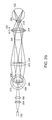
- FIG. 2A is a side view of the optical layout of an illustrative line-scanning laser ophthalmoscope (“LSLO”) that embodies principles of the invention.
- the LSLO is a simple, compact device which scans a focused laser line on the fundus.
- a laser 202 provides a substantially point source of light.
- the light is expanded to a line of light by lenses 204 , 206 which are cylindrical lenses.
- Other optical components can be substituted for the cylindrical lenses 204 , 206 to transform the substantially point source of light into a line of light.
- the line of light impinges on the turning prism or mirror 208 , and is redirected to the scanning mirror 210 .
- the scanning mirror 210 is caused to move by a drive, such as a galvanometer motor drive known in the art for driving mirrors.
- the line of light is scanned by the scanning mirror 210 and passes through one or more lenses 212 , 214 , 216 which are positioned and/or adjusted to pass the line of light through a cornea 218 of an eye and through an undilated pupil 220 of the eye so as to impinge as a line focused on a fundus of the eye, which includes the retina 222 of the eye.
- the laser line is imaged by the lenses 216 , 214 , 212 , 226 confocally to a linear CCD array 228 .
- the linear CCD array 228 is a DALSA camera with 512 14 ⁇ m pixels.
- a single galvanometer-driven mirror 210 performs the scan transverse to the laser line.
- the linear CCD readout is synchronized with scan motion and acquired with a frame grabber. A rectangular image of the fundus is thus obtained.
- the 830 nm laser diode is connected to the optical assembly of the LSLO via an FC fiber cable.
- 830 nm is an advantageous wavelength to use, because the human eye is insensitive to that wavelength, while infrared detectors having reasonable sensitivity are available. Accordingly, there is little or no pupillary reflex to the light, and little discomfort for the subject of the examination. Other infrared wavelengths can also be used to advantage.
- the human eye reacts strongly to visible light, with both contraction of the pupil and potentially, discomfort and a reaction involving motion of the eye. In the illustrative instrument, commercially available lenses are employed.
- the digital camera is a commercially available DALSA digital line-scan camera Model CB512, having a linear CCD array 228 (1 ⁇ 512) of 14 ⁇ m square silicon pixels.
- the gain in this model is not fully adjustable. Gain compensation is attained by operation at slower scan rates than would otherwise be possible. Different linear CCD arrays 228 with increased gain may be advantageously used.
- the DALSA camera body houses a number of low-density circuit cards.
- the linear CCD array itself is quite compact.
- a focus adjustment for the laser, and line rotation and displacement adjustments to align the laser line with the linear CCD array are provided with standard Newport tip/tilt mounts, rotary mounts, and slidemounts.
- the line confocal system is quickly aligned and optimized over the length of the array.
- the ophthalmoscopic lens slide 229 is used solely to correct for a very large range of ametropia.
- power and computer cables attach to the bottom of the DALSA camera body.
- the connections are eliminated and on-board batteries and an embedded computer are employed.
- the device weighs about 3 pounds, and can be lifted and manipulated rather easily.
- the LSLO configuration uses a single-mode fiber coupled 3 mW 830 nm laser 202 with an approximately gaussian profile.
- the laser is collimated and passed through a fixed cylindrical optic 204 , 206 having 25 mm focal length.
- the beam remains collimated on one transverse axis, but focuses near the pupil conjugate and then rapidly diverges on the other transverse axis.
- a 5 mm clear aperture prism mirror 208 turns the beam into the optical train, and also acts as a pupil stop 224 for pupil reflection and some scattered light, according to the Gullstrand principle.
- the galvanometer driven mirror 210 near this pupil conjugate vertically scans the beam. It has a 14 mm clear aperture.
- This pupil conjugate is imaged to the eye pupil with the scanning lens 212 (80 mm) and two ophthalmoscope lenses 214 , 216 , either the Volk Super 66 or the Volk 30D (66 or 30 diopters), all with NIR anti-reflection coatings.
- the 830 nm-optimized achromat scanning lens 212 was selected to produce a near diffraction-limited line at the retinal conjugates with good field flatness. These lenses are larger than necessary and are chosen merely for convenience, availability and cost.
- the pupil magnification at the turning mirror 208 (a pupil conjugate) with the Volk 66 is 5 ⁇ , and the beam size at the eye entrance pupil 220 is 1 mm (2.4 ⁇ magnification and ⁇ 2 mm pupil for the Volk 30D).
- the measured power at the pupil 220 is less than 2 mW.
- the eye focuses the beam to near the diffraction limit in the vertical axis on the retina 222 , but fans the beam rapidly on the other axis. This reduces the power density at the retina 222 , relative to a diffraction-limited spot, by a factor of more than 500, e.g., the aspect ratio of the laser line.
- the same magnifications give the corresponding size of the scanning mirror aperture at the exit pupil: for the Volk 66, the exit pupil is 3 mm, and for the 30D, as much as 6 mm. In the latter case, the iris of the eye usually will be the limiting stop. As long as the pupil is large enough to collect light around the illumination pupil stop, the LSLO will function.
- the collected de-scanned light is imaged by the objective lens onto the linear CCD array.
- the lens selected is a 40 mm achromat, but is neither optimized at 830 nm, nor AR-coated. This lens is less critical but will affect in-line resolution to some extent.
- the use of custom lenses may allow optimization at a selected wavelength.
- FIG. 2B is a top view of the optical layout of the illustrative line-scanning laser ophthalmoscope that is depicted in FIG. 2 A. Both the top and side view are shown because the cylindrical optic 204 , 206 requires both tangential and sagittal views to visualize its operation.
- the side view shows the pupil separation at the small turning prism mirror 208 that allows the illuminating (incoming) beam to pass to the retina 222 while acting as a stop for corneal reflections.
- the LSLO is indistinguishable from its point-scanning cousin, the SLO.
- the top view shows the action of the cylindrical lens 204 , 206 which focuses at the pupil conjugate and diverges to a tightly focused laser line 230 at the retina 222 .
- the line 230 is scanned on the retina 222 by the scanning mirror 210 and the reflection is descanned and imaged to the linear CCD array 228 .
- the LSLO of the present invention preserves advantages such as rejection of interfering scattered light, and rejection of light scattered from defocused planes above and below the focal plane, even though an entire line is imaged at once.
- focal plane is understood to mean a conjugate to the image plane where the detector or confocal aperture lies.
- MTF Modulation Transfer Function
- PSF Point Spread Function
- the total power at any given pixel is the sum of all such contributions over the entire illuminated area (ignoring scattering).
- the SLO is ideal and nearly background-free because there are no other illuminated regions: the “flying spot” is the only light source.
- the total LSLO background pixel power is effectively a line integral along a strip through the center of the PSF since only a line of illumination is used.
- Ordinary CCD imaging is a complete surface integral over the PSF, to the limits of the illuminated area. The limiting contrast is found from FIG.
- the focal image contrast is best for the SLO, and worst for standard fundus imaging.
- the LSLO lies somewhere in between. The sharper the PSF relative to the pixel size, the smaller the difference in focal plane performance of the LSLO relative to that of the SLO.
- FIGS. 4A-4C Three imaging schemes are illustrated in FIGS. 4A-4C.
- FIG. 4A illustrates the optical effect of defocusing in a prior art full field imaging method.
- the media above or below the focal plane scatters light
- full field illumination results in a severe defect, as will be explained.
- uniform light 405 impinges on a focal plane 410 .
- a reflection at a defocused plane 420 at distance Z from the focal plane 410 will provide a defocused image 430 comprising a large blur circle at the detector plane.
- the behavior of the intensity with Z is analyzed for three cases, namely full field imaging, “flying spot” imaging, and line scan imagining.
- the function of Z obtained by first integrating over the area at each Z plane, is a “range gate” which describes sensitivity to scatter from regions above or below the focal plane. Actual evaluation of these integrals is made rather complex by aperture shape. However, the approximate dependence of the area integrals on Z can be found by inspection.
- the intensity of the defocused reflected light at each pixel drops off as Z ⁇ 2 .
- the area producing this illumination on that pixel increases with Z 2 . This occurs at every layer in the sample. Integrating just over area, the resulting range gate function is approximately constant, i.e., independent of Z. This means there is no effective range gate. Every layer in the resulting image is weighted only by it intrinsic reflectivity. Unless the reflectance is strongly confined to a region very near the focal plane, the image contrast is quickly overwhelmed by defocused light.
- MTF [ I max ⁇ ( k ) - I min ⁇ ( k ) ] [ I max ⁇ ( k ) + I min ⁇ ( k ) + 2 ⁇ I defocus ] ( 2 )
- I min (k) and I max (k) give the ideal focal plane contrast at given spatial frequency, and the defocused light intensity shows the effect of background light on contrast: I defocus increases directly with Z-thickness in a uniformly scattering medium. Therefore, the full field imaging method is unsuitable in scattering media where the thickness of the sample is greater than the depth of field scale (8F 2 ). Contrast is halved when volume-integrated scattering anywhere in the optical path is equal to the focal plane reflection. This is the source of the sensitivity of conventional fundus image contrast to media clarity.
- FIG. 4B shows the optical effect of defocusing in a confocal “flying spot” system of the prior art.
- the equation for the intensity I (X,Y) remains the same except for a modification as a consequence of focusing the illuminating laser light to a point confocal with the aperture. This adds an identical defocus factor in the denominator in equation (1).
- the range defocus light falls off as Z ⁇ 4 , rather than Z ⁇ 2 .
- Integrating over area, the resultant range gate function has dimensions of Z ⁇ 2 .
- the full gate width at half maximum is just the usual definition of the depth of field. This weighting of ⁇ is integrable in Z, so that uniform scattering from surrounding tissue will not destroy focal plane image contrast.
- the confocal flying spot method of the prior art provides intrinsic sectioning properties, limited only by extinction due to absorption and scatter.
- FIG. 4C illustrates the optical effect of defocusing in a line scanning imaging system such as the LSLO of the invention.
- the system focuses the laser light 435 to a line confocal with the linear detector array 440 by use of optical components 450 .
- the illumination intensity falls off as Z ⁇ 1 .
- the defocused intensity therefore falls off as Z ⁇ 3 .
- Integrating over area, the resultant range gate function has Z ⁇ 1 dependence, with a gate width proportional to the depth of field.
- this weighting of ⁇ is not integrable in Z. Rather, it has only a weak logarithmic divergence. Uniform scattering from surrounding tissue will reduce focal plane image contrast. Nevertheless, a line scanning system provides useful sectioning properties, because contrast falls off much less rapidly in thick samples, and is far less sensitive to more remote media opacities.
- Laser imaging systems generally tend to exhibit speckle patterns, and this is so for both the SLO and the LSLO. Except near smooth interfaces with changes in refractive index, biological systems tend to scatter light from spatially distributed sites, with sizes and separations from nanometers to microns. Because the laser light is spatially coherent, this means that the phase relationships of the reflections along the beam (at least within one coherence length) are preserved. The total intensity of the light collected from such a region is the coherent sum of many contributions. The random walk nature of the amplitude sum leads to constructive and destructive interference with large variations in power falling on the aperture or on each pixel, especially if the aperture or the pixel size is near the diffraction limit. The diffraction limit can be thought of as “one speckle” in the transverse direction.
- the light gathering behavior of a LSLO embodying principles of the invention is compared to a standard point-scanning system.
- the model used for calculation assumes identical optical geometries and detector quantum efficiencies. Both systems are modeled to scan vertically at the framing rate.
- the horizontal scan rate f H of the SLO is 15 kHz.
- the “flying spot” detector requires a bandwidth of f H times the number of pixels per line, N Hpix .
- the bandwidth is more than 10 MHz. This can be achieved because the full power of up to a few milliwatts is focused at the retina confocally with the detector aperture.
- the reflected power collected depends upon the incident power P I (say 1 mW), the local reflectance, R(X,Y), of the retina (less than 10% in NIR), and the collection solid angle ⁇ ( ⁇ 10 ⁇ 3 sr). This amounts to a typical range from about 1 to about 100 nW.
- the noise-equivalent power (NEP) of the silicon detector is one noise contribution, and another is shot noise.
- An acceptable signal-to-noise ratio SNR is easily reached within the required bandwidth.
- the dynamic range of 8-bit images requires a SNR>255 to fully utilize the available range, that is, a noise level less than the signal strength represented by the least significant bit.
- ⁇ is the quantum efficiency and E v is the energy per photon at the illuminating wavelength.
- the thermal noise of a small silicon photodetector can be ⁇ 10 ⁇ 15 W/(Hz) 1/2 .
- Readout noise of a read-out amplifier will usually dominate the NEP for silicon photodetectors.
- the LSLO images an entire line at once. No transverse scan is required.
- the readout of the linear CCD array represents a “scan,” but it can be performed during the time that the line is repositioned.
- the effective integration time is 1/f H , instead of 1/f H N Hpix as for the flying spot system.
- the line scanner must spread the beam with a cylindrical optic to form a line covering all N Hpix at once.
- the power at each pixel is reduced in proportion to the number of pixels: P I per pixel for the SLO becomes P I /N Hpix for the LSLO. Therefore the equation, and the shot-noise limited SNR, is unchanged and the line scan and flying spot systems are equivalent as regards SNR.
- the model can also be extended to evaluate the full image case of the prior art.
- the power level per pixel is reduced still further by another factor of N lines ( ⁇ N Hpix ).
- the detector/amplifier noise is most likely to dominate, and CCD imaging becomes noisy at these low eye-safe light levels. Flash fundus imaging or higher illumination powers must be used, and all confocal advantages are lost.
- the operation of the LSLO has been tested to determine the resolving power and diffraction limits of the system, using both biological samples, such as an eye, and inanimate, mechanically produced targets.
- the best focused beam width based on resolution targets appears to be somewhat larger. This is attributable in part to aberrations in some non-optimized elements with the optical train, and perhaps to forward scatter from optical surfaces.
- the pixel size referenced to the retina is designed to roughly match these beam widths.
- the pixel diagonals at the model retina are 40 ⁇ m and 20 ⁇ m respectively.
- the horizontal and vertical Nyquist limit is twice the pixel spacing or 56 ⁇ m and 28 ⁇ m for the two magnifications, or 17 and 35 line pairs per millimeter.
- the Airy diffraction at the CCD array due to the 40 mm objective is 11.7 ⁇ m and 5.8 ⁇ m.
- the net double-pass image optical resolution element is the root-mean-square sum of these contributions, or 58 ⁇ m and 29 ⁇ m. This closely matches the Nyquist limit of the pixel array.
- FIGS. 5A and 5B show the standard United States Air Force (USAF) resolution target #51 at low and high magnification, respectively.
- USAF United States Air Force
- the model eye consists of an achromat in front of the planar target, ophthalmoscopic lenses overcorrect for field curvature that would be present in the eye.
- the bright central region is due to field curvature moving target plane out of the depth of field at high scan angles.
- Resolution is determined by reading off the group and line number of the smallest resolvable line triplet.
- the resolutions judging from the limits of visibility of the USAF target triplets, are:
- the widths of the laser line were w/2 n8f/d ⁇ 40 microns with the Volk 66, or ⁇ 20 microns with the 30D.
- the length of the laser line was set to cover the fields of interest of about 40 degree and 20 degree horizontal.
- the FWHM has been scaled via the focal length of the fixed cylindrical lens, to no less than 7 mm at the model retina. Approximately 1 mW of power falls fairly uniformly on the central 7 mm of the line, which is useful for power density calculations in the worst case (e.g., use of the 30D optic):
- Stationary Line Power Density at the retina 1 mW/(wL) ⁇ 500 mW/cm 2 .
- Safe exposure times at such power densities at 830 nm is at least 10 seconds, and consistent with the time needed to for the subjects to avert their gaze, or for the operator to block the incoming light or turn off the light source in the event of scanner failure.
- a plane wave equivalent at the cornea can be estimated by determining the power at the cornea which corresponds to this power density on a single 30 ⁇ 30 micron spot, i.e., one virtual laser element of the line. This is simply ⁇ fraction (1/250) ⁇ th of the incident power, or less than about 4 ⁇ W.
- the key safety feature of the LSLO is that even if the vertical scanner fails, no laser interlock is needed because the stationary line itself is eye-safe over the few seconds required to move the volunteer's eye away.
- the fixed cylindrical optic which cannot be removed without disassembling the instrument, ensures that the power density at the retina can never be greater that the quoted values.
- the LSLO of the invention has been compared with SLOs of the prior art through the acquisition of wide field images.
- Forty degree field LSLO images in the left and right eyes of a human subject are shown in FIGS. 7A and 7B, respectively.
- Sharp images were obtained with the LSLO, and typical characteristics of confocal infrared image were seen: a dark disc, well-resolved bright vessel lumen, lighter arteries and darker veins, foveal reflex in some subjects, capillaries and choroidal vessels, and variations in pigmentation.
- FIG. 7A depicting the left eye, shows a retinal scar and some residual features of prior central serous retinopathy. Because of the relatively small pupil required for these images and the modest depth of field, clear images can be obtained well into the periphery.
- a standard SLO image of the prior art at slightly higher magnification is shown in FIG. 8 .
- the capabilities of the LSLO of the invention are demonstrated by recording macular and disc images.
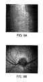
- a selection of twenty degree field LSLO images in a human subject are shown in FIGS. 9A and 9B.
- the images distinctly show veins and arteries, retinal nerve fiber foveal reflex, and other morphology.
- the LSLO provides the ability to collect stereo pairs.
- the pupil aperture is optically split and two images are captured corresponding to the left and right fields.
- the parallax between the images contains the depth information.
- Depth of field is determined by the numerical apertures of the individual fields. Because of the finite depth of field of the LSLO with different viewing angles, it is equally effective at gathering depth information. But in addition, due to its confocality, defocused light from above and below the plane of focus is suppressed. This allows superior 3D visualization of deeper retinal structures.
- FIGS. 10A and 10B show illustrative disc image pairs captured in succession with the LSLO, with an approximately 1 to 2 mm lateral shift in pupil position.
- This purely lateral pupil shift allowed the same image to be captured at two viewing angles separated by 3 to 6 degrees and is an effective simulation of anticipated live-motion, split-pupil aperture binocular LSLO operation.
- These images are displayed side-by-side in FIGS. 10A and 10B at the appropriate separation, so that when viewed from 2 feet (60 cm) or more from the page, the image can be made to fuse in a stereo view.
- FIGS. 10A and 10B the shapes and orientations of the vessels near the disc are clearly visible. Left/right focus is slightly different due to successive image capture. The perception of a mild fogginess in the images is due to the low resolution in the images (500 ⁇ 512), and speckle. High resolution images, and perhaps super luminescent diode (SLD) illumination, should greatly reduce granularity.
- SLD super luminescent diode
- FIG. 11 shows a demonstration of confocal and anterior segment imaging.
- the image of FIG. 11 was obtained when the ophthalmoscopic objective was removed and the anterior segment of the subject's eye was placed at the conjugate image plane.
- An embodiment of the LSLO of the invention preferably operates at two magnifications, and is configurable to permit imaging of an anterior segment and non-mydriatic imaging of the posterior segment. In one embodiment, this is accomplished using one of two interchangable ophthalmoscopic lenses with rotary focus. In other embodiments, the ophthalmoscopic lenses are demountable, and can be interchanged, or the LSLO can be operated without an ophthalmoscopic lens.
- the LSLO device incorporates all necessary electronics and optics for image acquisition, without the need for external image acquisition, a computer or a CRT.
- the LSLO device provides on-board camera captured image storage and image downloading.
- Dual channels can be integrated that can be configured for multi-wavelength operation and real time binocular imaging.
- Wearable micro-display technology permits the operator to manipulate the device with an unobstructed visual field, while glancing a few degrees off axis, such as upward or downward, to the color/stereo (left and right eye) display. The displays appear to merge near the hand-held device so that minimal accommodation is needed while shifting gaze from patient to stereo display.
- the use of an adjustable facial support system or mask which makes possible the operator gently holding the apparatus in place adjacent to the patient, provides all the stability and articulation that the lightweight LSLO needs for patients in any orientation.
Landscapes
- Life Sciences & Earth Sciences (AREA)
- Health & Medical Sciences (AREA)
- Medical Informatics (AREA)
- Molecular Biology (AREA)
- Ophthalmology & Optometry (AREA)
- Engineering & Computer Science (AREA)
- Biomedical Technology (AREA)
- Heart & Thoracic Surgery (AREA)
- Physics & Mathematics (AREA)
- Biophysics (AREA)
- Surgery (AREA)
- Animal Behavior & Ethology (AREA)
- General Health & Medical Sciences (AREA)
- Public Health (AREA)
- Veterinary Medicine (AREA)
- Eye Examination Apparatus (AREA)
- Microscoopes, Condenser (AREA)
- Facsimile Heads (AREA)
Priority Applications (10)
| Application Number | Priority Date | Filing Date | Title |
|---|---|---|---|
| US10/171,883 US6758564B2 (en) | 2002-06-14 | 2002-06-14 | Line-scan laser ophthalmoscope |
| DE60335625T DE60335625D1 (de) | 2002-06-14 | 2003-06-13 | Ophthalmoskop mit linienförmiger laserstrahl-abtastung |
| AT03741989T ATE493928T1 (de) | 2002-06-14 | 2003-06-13 | Ophthalmoskop mit linienförmiger laserstrahl- abtastung |
| AU2003276035A AU2003276035A1 (en) | 2002-06-14 | 2003-06-13 | Line-scan laser ophthalmoscope |
| PCT/US2003/018839 WO2003105679A1 (en) | 2002-06-14 | 2003-06-13 | Line-scan laser ophthalmoscope |
| CA2489241A CA2489241C (en) | 2002-06-14 | 2003-06-13 | Line-scan laser ophthalmoscope |
| EP03741989A EP1513441B1 (en) | 2002-06-14 | 2003-06-13 | Line-scan laser ophthalmoscope |
| JP2004512595A JP4621496B2 (ja) | 2002-06-14 | 2003-06-13 | ラインスキャン検眼鏡 |
| US10/864,081 US7284859B2 (en) | 2002-06-14 | 2004-06-09 | Line-scan laser ophthalmoscope |
| US11/043,028 US7404640B2 (en) | 2002-06-14 | 2005-01-25 | Monitoring blood flow in the retina using a line-scanning laser ophthalmoscope |
Applications Claiming Priority (1)
| Application Number | Priority Date | Filing Date | Title |
|---|---|---|---|
| US10/171,883 US6758564B2 (en) | 2002-06-14 | 2002-06-14 | Line-scan laser ophthalmoscope |
Related Child Applications (1)
| Application Number | Title | Priority Date | Filing Date |
|---|---|---|---|
| US10/864,081 Continuation US7284859B2 (en) | 2002-06-14 | 2004-06-09 | Line-scan laser ophthalmoscope |
Publications (2)
| Publication Number | Publication Date |
|---|---|
| US20030231285A1 US20030231285A1 (en) | 2003-12-18 |
| US6758564B2 true US6758564B2 (en) | 2004-07-06 |
Family
ID=29732880
Family Applications (2)
| Application Number | Title | Priority Date | Filing Date |
|---|---|---|---|
| US10/171,883 Expired - Lifetime US6758564B2 (en) | 2002-06-14 | 2002-06-14 | Line-scan laser ophthalmoscope |
| US10/864,081 Expired - Lifetime US7284859B2 (en) | 2002-06-14 | 2004-06-09 | Line-scan laser ophthalmoscope |
Family Applications After (1)
| Application Number | Title | Priority Date | Filing Date |
|---|---|---|---|
| US10/864,081 Expired - Lifetime US7284859B2 (en) | 2002-06-14 | 2004-06-09 | Line-scan laser ophthalmoscope |
Country Status (8)
| Country | Link |
|---|---|
| US (2) | US6758564B2 (und) |
| EP (1) | EP1513441B1 (und) |
| JP (1) | JP4621496B2 (und) |
| AT (1) | ATE493928T1 (und) |
| AU (1) | AU2003276035A1 (und) |
| CA (1) | CA2489241C (und) |
| DE (1) | DE60335625D1 (und) |
| WO (1) | WO2003105679A1 (und) |
Cited By (35)
| Publication number | Priority date | Publication date | Assignee | Title |
|---|---|---|---|---|
| US20050080467A1 (en) * | 2003-10-14 | 2005-04-14 | Nidek Co., Ltd | Laser treatment apparatus |
| US20050117782A1 (en) * | 2002-03-29 | 2005-06-02 | Takuya Imaoka | Eye imaging device |
| US20060228011A1 (en) * | 2005-04-06 | 2006-10-12 | Everett Matthew J | Method and apparatus for measuring motion of a subject using a series of partial images from an imaging system |
| US20070252951A1 (en) * | 2006-04-24 | 2007-11-01 | Hammer Daniel X | Stabilized retinal imaging with adaptive optics |
| US20070263171A1 (en) * | 2006-05-01 | 2007-11-15 | Ferguson R D | Hybrid spectral domain optical coherence tomography line scanning laser ophthalmoscope |
| EP1875857A1 (de) * | 2006-07-07 | 2008-01-09 | SensoMotoric Instruments GmbH | Ophthalmoskop |
| US7359563B1 (en) * | 2004-04-05 | 2008-04-15 | Louisiana Tech University Research Foundation | Method to stabilize a moving image |
| US20090009715A1 (en) * | 2007-07-04 | 2009-01-08 | I-Optics Bv | Confocal Color Ophthalmoscope |
| WO2010087251A1 (ja) | 2009-01-30 | 2010-08-05 | 興和株式会社 | 光学撮像装置 |
| US20100195048A1 (en) * | 2009-01-15 | 2010-08-05 | Physical Sciences, Inc. | Adaptive Optics Line Scanning Ophthalmoscope |
| US20100245765A1 (en) * | 2008-10-28 | 2010-09-30 | Dyer Holdings, Llc | Video infrared ophthalmoscope |
| US20100277702A1 (en) * | 2009-04-29 | 2010-11-04 | Jacques Gollier | Laser Projection System With a Spinning Polygon for Speckle Mitigation |
| WO2011091253A2 (en) | 2010-01-21 | 2011-07-28 | Physical Sciences, Inc. | Multi-functional adaptive optics retinal imaging |
| US20110222731A1 (en) * | 2008-11-21 | 2011-09-15 | Henry Hacker | Computer Controlled System for Laser Energy Delivery to the Retina |
| WO2012071387A3 (en) * | 2010-11-24 | 2012-09-27 | University Of South Florida | Adaptive optics ophthalmic imager without wavefront sensor or wavefront corrector |
| EP2517618A2 (en) | 2011-04-27 | 2012-10-31 | Canon Kabushiki Kaisha | Ophthalmic apparatus, method of controlling ophthalmic apparatus and storage medium |
| US20130144277A1 (en) * | 2011-11-25 | 2013-06-06 | Christian Rathjen | Device for processing eye tissue by means of a pulsed laser beam |
| US8711366B2 (en) | 2005-01-21 | 2014-04-29 | Carl Zeiss Meditec, Inc. | Method of motion correction in optical coherence tomography imaging |
| US8842273B2 (en) | 2013-02-14 | 2014-09-23 | United Sciences, Llc | Optical measurement of drilled holes |
| US8841603B1 (en) | 2013-08-28 | 2014-09-23 | United Sciences, Llc | Illumination for optical scan and measurement |
| US8857988B2 (en) | 2011-07-07 | 2014-10-14 | Carl Zeiss Meditec, Inc. | Data acquisition methods for reduced motion artifacts and applications in OCT angiography |
| US9033510B2 (en) | 2011-03-30 | 2015-05-19 | Carl Zeiss Meditec, Inc. | Systems and methods for efficiently obtaining measurements of the human eye using tracking |
| US9055896B2 (en) | 2009-09-29 | 2015-06-16 | Od-Os Gmbh | Ophthalmoscope for observing an eye |
| US9532712B2 (en) | 2009-09-29 | 2017-01-03 | Od-Os Gmbh | Ophthalmoscope having a laser device |
| US9706914B2 (en) | 2012-01-19 | 2017-07-18 | Carl Zeiss Meditec, Inc. | Systems and methods for enhanced accuracy in OCT imaging of the cornea |
| WO2017137999A1 (en) * | 2016-02-11 | 2017-08-17 | Eduardo Svetliza | Wide angle stereoscopic funduscopy |
| EP3272395A1 (en) | 2007-12-23 | 2018-01-24 | Carl Zeiss Meditec, Inc. | Devices for detecting, controlling, and predicting radiation delivery |
| US20180116508A1 (en) * | 2013-09-30 | 2018-05-03 | Carl Zeiss Meditec, Inc. | High temporal resolution doppler oct imaging of retinal blood flow |
| US10105049B2 (en) | 2015-01-16 | 2018-10-23 | Massachusetts Institute Of Technology | Methods and apparatus for anterior segment ocular imaging |
| US20190015250A1 (en) * | 2017-07-13 | 2019-01-17 | Ziemer Ophthalmic Systems Ag | Apparatus for Working on Eye Tissue by Means of a Pulsed Laser Beam |
| WO2020106792A1 (en) | 2018-11-21 | 2020-05-28 | University Of Washington | System and method for retina template matching in teleophthalmology |
| WO2021019025A1 (en) | 2019-08-01 | 2021-02-04 | Carl Zeiss Meditec, Inc. | Ophthalmic imaging with k-mirror scanning, efficient interferometry, and pupil alignment through spatial frequency analysis |
| WO2021049558A1 (en) | 2019-09-11 | 2021-03-18 | Topcon Corporation | Method and apparatus for stereoscopic color eye imaging |
| US11284795B2 (en) | 2013-03-15 | 2022-03-29 | Carl Zeiss Meditec, Inc. | Systems and methods for broad line fundus imaging |
| US12611102B2 (en) * | 2020-04-06 | 2026-04-28 | Topcon Corporation | Ophthalmic apparatus |
Families Citing this family (94)
| Publication number | Priority date | Publication date | Assignee | Title |
|---|---|---|---|---|
| US7288106B2 (en) * | 2002-10-03 | 2007-10-30 | Light Sciences Oncology, Inc. | System and method for excitation of photoreactive compounds in eye tissue |
| DE10336475B9 (de) | 2003-08-08 | 2006-09-07 | Carl Zeiss | Mikroskopiesystem |
| US20050097046A1 (en) * | 2003-10-30 | 2005-05-05 | Singfield Joy S. | Wireless electronic check deposit scanning and cashing machine with web-based online account cash management computer application system |
| US20080284848A1 (en) * | 2005-08-26 | 2008-11-20 | Peter Martin | Security surveillance planning tool kit |
| US8708227B1 (en) | 2006-10-31 | 2014-04-29 | United Services Automobile Association (Usaa) | Systems and methods for remote deposit of checks |
| US7873200B1 (en) | 2006-10-31 | 2011-01-18 | United Services Automobile Association (Usaa) | Systems and methods for remote deposit of checks |
| JP4915737B2 (ja) * | 2007-03-13 | 2012-04-11 | 興和株式会社 | 画像解析システム、及び画像解析プログラム |
| US10380559B1 (en) | 2007-03-15 | 2019-08-13 | United Services Automobile Association (Usaa) | Systems and methods for check representment prevention |
| KR100965723B1 (ko) | 2007-03-21 | 2010-06-24 | 삼성전자주식회사 | 무선통신시스템의 물리하향제어채널의 자원 매핑 방법 및매핑된 물리하향제어채널의 송/수신 장치 |
| US9058512B1 (en) | 2007-09-28 | 2015-06-16 | United Services Automobile Association (Usaa) | Systems and methods for digital signature detection |
| US9159101B1 (en) | 2007-10-23 | 2015-10-13 | United Services Automobile Association (Usaa) | Image processing |
| US9892454B1 (en) | 2007-10-23 | 2018-02-13 | United Services Automobile Association (Usaa) | Systems and methods for obtaining an image of a check to be deposited |
| DE102008000225B3 (de) * | 2008-02-01 | 2009-03-26 | Linos Photonics Gmbh & Co. Kg | Fundusabtastvorrichtung |
| US10380562B1 (en) | 2008-02-07 | 2019-08-13 | United Services Automobile Association (Usaa) | Systems and methods for mobile deposit of negotiable instruments |
| EP2306889A4 (en) * | 2008-07-10 | 2012-11-28 | Univ Indiana Res & Tech Corp | OPHTHALMIC APPARATUS, SYSTEMS AND METHODS |
| US10504185B1 (en) | 2008-09-08 | 2019-12-10 | United Services Automobile Association (Usaa) | Systems and methods for live video financial deposit |
| US8452689B1 (en) | 2009-02-18 | 2013-05-28 | United Services Automobile Association (Usaa) | Systems and methods of check detection |
| US10956728B1 (en) | 2009-03-04 | 2021-03-23 | United Services Automobile Association (Usaa) | Systems and methods of check processing with background removal |
| EP2413778B8 (en) * | 2009-04-01 | 2019-09-25 | Centervue S.P.A. | Instrument for eye examination |
| US9779392B1 (en) | 2009-08-19 | 2017-10-03 | United Services Automobile Association (Usaa) | Apparatuses, methods and systems for a publishing and subscribing platform of depositing negotiable instruments |
| US8977571B1 (en) | 2009-08-21 | 2015-03-10 | United Services Automobile Association (Usaa) | Systems and methods for image monitoring of check during mobile deposit |
| US8699779B1 (en) | 2009-08-28 | 2014-04-15 | United Services Automobile Association (Usaa) | Systems and methods for alignment of check during mobile deposit |
| DE102009041996A1 (de) * | 2009-09-18 | 2011-03-24 | Carl Zeiss Meditec Ag | Ophthalmologisches Biometrie- oder Bilderzeugungssystem und Verfahren zur Erfassung und Auswertung von Messdaten |
| WO2011050164A1 (en) | 2009-10-21 | 2011-04-28 | Avedro, Inc. | Eye therapy |
| US20110237999A1 (en) | 2010-03-19 | 2011-09-29 | Avedro Inc. | Systems and methods for applying and monitoring eye therapy |
| US9129340B1 (en) | 2010-06-08 | 2015-09-08 | United Services Automobile Association (Usaa) | Apparatuses, methods and systems for remote deposit capture with enhanced image detection |
| NL2005253C2 (en) * | 2010-08-23 | 2012-02-27 | Optics B V I | Confocal line-scan ophthalmoscope. |
| CN102068236B (zh) * | 2010-12-17 | 2012-05-23 | 中国科学院光电技术研究所 | 一种基于激光衍射的线扫描共焦检眼镜系统和方法 |
| JP5635898B2 (ja) | 2010-12-17 | 2014-12-03 | キヤノン株式会社 | 眼底撮像装置及びその制御方法 |
| CN102008288B (zh) * | 2010-12-17 | 2012-02-01 | 中国科学院光电技术研究所 | 一种线扫描共焦检眼镜的系统和方法 |
| US9044308B2 (en) | 2011-05-24 | 2015-06-02 | Avedro, Inc. | Systems and methods for reshaping an eye feature |
| WO2012167260A2 (en) | 2011-06-02 | 2012-12-06 | Avedro, Inc. | Systems and methods for monitoring time based photo active agent delivery or photo active marker presence |
| JP6057567B2 (ja) | 2011-07-14 | 2017-01-11 | キヤノン株式会社 | 撮像制御装置、眼科撮像装置、撮像制御方法及びプログラム |
| DE102011053880B4 (de) | 2011-09-23 | 2023-11-09 | Carl Zeiss Ag | Vorrichtung und Verfahren zum Abbilden eines Augenhintergrunds |
| US10380565B1 (en) | 2012-01-05 | 2019-08-13 | United Services Automobile Association (Usaa) | System and method for storefront bank deposits |
| US20130229620A1 (en) * | 2012-03-05 | 2013-09-05 | Daniel X. Hammer | Enhanced Sensitivity Line Field Detection |
| US9808154B2 (en) * | 2012-07-13 | 2017-11-07 | Retina Biometrix, Llc | Biometric identification via retina scanning with liveness detection |
| WO2014012102A2 (en) * | 2012-07-13 | 2014-01-16 | Retina Biometrix, Llc | Biometric identification via retina scanning |
| WO2013059837A2 (en) | 2012-07-16 | 2013-04-25 | Avedro, Inc. | Systems and methods for corneal cross-linking with pulsed light |
| US10552810B1 (en) | 2012-12-19 | 2020-02-04 | United Services Automobile Association (Usaa) | System and method for remote deposit of financial instruments |
| EP2967325A4 (en) * | 2013-03-15 | 2017-03-08 | NeuroVision Imaging LLC | System and method for rejecting afocal light collected from an in vivo human retina |
| CN105208916A (zh) | 2013-03-15 | 2015-12-30 | 瓦索普蒂克医疗公司 | 使用多种照明形态的眼科检查及疾病管理 |
| US20140347631A1 (en) * | 2013-05-23 | 2014-11-27 | Canon Kabushiki Kaisha | Ophthalmologic imaging apparatus and control method therefor |
| US9498114B2 (en) | 2013-06-18 | 2016-11-22 | Avedro, Inc. | Systems and methods for determining biomechanical properties of the eye for applying treatment |
| WO2014205145A1 (en) | 2013-06-18 | 2014-12-24 | Avedro, Inc. | Systems and methods for determining biomechanical properties of the eye for applying treatment |
| US11138578B1 (en) | 2013-09-09 | 2021-10-05 | United Services Automobile Association (Usaa) | Systems and methods for remote deposit of currency |
| US9286514B1 (en) | 2013-10-17 | 2016-03-15 | United Services Automobile Association (Usaa) | Character count determination for a digital image |
| US9949637B1 (en) | 2013-11-25 | 2018-04-24 | Verily Life Sciences Llc | Fluorescent imaging on a head-mountable device |
| US9211064B2 (en) | 2014-02-11 | 2015-12-15 | Welch Allyn, Inc. | Fundus imaging system |
| US9237847B2 (en) | 2014-02-11 | 2016-01-19 | Welch Allyn, Inc. | Ophthalmoscope device |
| US20150250383A1 (en) * | 2014-03-05 | 2015-09-10 | Annidis Corporation | Real time visualization of surgical operations on the eye |
| GB2528102B (en) * | 2014-07-10 | 2020-04-29 | Optos Plc | Ophthalmoscopes |
| KR102416876B1 (ko) | 2014-10-27 | 2022-07-05 | 아베드로 인코퍼레이티드 | 눈의 교차-결합 처리를 위한 시스템 및 방법 |
| US10114205B2 (en) | 2014-11-13 | 2018-10-30 | Avedro, Inc. | Multipass virtually imaged phased array etalon |
| US10799115B2 (en) * | 2015-02-27 | 2020-10-13 | Welch Allyn, Inc. | Through focus retinal image capturing |
| US11045088B2 (en) * | 2015-02-27 | 2021-06-29 | Welch Allyn, Inc. | Through focus retinal image capturing |
| EP3285704B1 (en) | 2015-04-24 | 2020-11-18 | Avedro Inc. | Systems for photoactivating a photosensitizer applied to an eye |
| US10028657B2 (en) | 2015-05-22 | 2018-07-24 | Avedro, Inc. | Systems and methods for monitoring cross-linking activity for corneal treatments |
| US10402790B1 (en) | 2015-05-28 | 2019-09-03 | United Services Automobile Association (Usaa) | Composing a focused document image from multiple image captures or portions of multiple image captures |
| US11207410B2 (en) | 2015-07-21 | 2021-12-28 | Avedro, Inc. | Systems and methods for treatments of an eye with a photosensitizer |
| US10136804B2 (en) | 2015-07-24 | 2018-11-27 | Welch Allyn, Inc. | Automatic fundus image capture system |
| WO2017062189A1 (en) * | 2015-08-27 | 2017-04-13 | Retina Biometrix, Llc | Biometric identification via retina scanning with liveness detection |
| JP6651747B2 (ja) * | 2015-09-02 | 2020-02-19 | 株式会社ニデック | 走査型レーザ検眼鏡 |
| US10506165B2 (en) | 2015-10-29 | 2019-12-10 | Welch Allyn, Inc. | Concussion screening system |
| US10772495B2 (en) | 2015-11-02 | 2020-09-15 | Welch Allyn, Inc. | Retinal image capturing |
| CN105351783A (zh) * | 2015-12-04 | 2016-02-24 | 珠海惠尔益电子有限公司 | 一种接插式灯泡联接结构 |
| US10413179B2 (en) | 2016-01-07 | 2019-09-17 | Welch Allyn, Inc. | Infrared fundus imaging system |
| CN107126189B (zh) * | 2016-05-31 | 2019-11-22 | 瑞尔明康(杭州)医疗科技有限公司 | 用于视网膜成像的光学组件和视网膜成像设备 |
| US10602926B2 (en) | 2016-09-29 | 2020-03-31 | Welch Allyn, Inc. | Through focus retinal image capturing |
| US10285589B2 (en) | 2016-09-30 | 2019-05-14 | Welch Allyn, Inc. | Fundus image capture system |
| JP7035081B2 (ja) | 2017-01-11 | 2022-03-14 | アヴェドロ・インコーポレーテッド | 角膜におけるクロスリンキング分布及び/又は角膜の構造的特徴を決定するためのシステム及び方法 |
| WO2019018258A1 (en) * | 2017-07-17 | 2019-01-24 | Welch Allyn, Inc. | RETINAL IMAGE CAPTURE WITH CROSSING FIREPLACE |
| WO2019138916A1 (ja) * | 2018-01-10 | 2019-07-18 | 株式会社ニデック | 眼底撮影装置 |
| JP6958367B2 (ja) * | 2018-01-10 | 2021-11-02 | 株式会社ニデック | 眼底撮影装置 |
| EP4397287A3 (en) | 2018-03-05 | 2024-09-11 | Avedro, Inc. | System for eye tracking during eye treatment |
| WO2019173762A1 (en) | 2018-03-08 | 2019-09-12 | Avedro, Inc. | Micro-devices for treatment of an eye |
| US11030752B1 (en) | 2018-04-27 | 2021-06-08 | United Services Automobile Association (Usaa) | System, computing device, and method for document detection |
| CN108524097B (zh) * | 2018-05-14 | 2024-02-02 | 苏州君信视达医疗科技有限公司 | 一种激光治疗成像装置 |
| US11096574B2 (en) | 2018-05-24 | 2021-08-24 | Welch Allyn, Inc. | Retinal image capturing |
| CN113316411B (zh) | 2018-09-19 | 2025-01-17 | 艾维德洛公司 | 用于眼部治疗期间的眼部追踪的系统及方法 |
| CN113329723A (zh) | 2018-09-19 | 2021-08-31 | 艾维德洛公司 | 治疗角膜扩张型疾病的系统和方法 |
| US12029486B2 (en) | 2018-09-28 | 2024-07-09 | Carl Zeiss Meditec, Inc. | Low cost fundus imager with integrated pupil camera for alignment aid |
| EP3863576A4 (en) | 2018-10-09 | 2022-07-06 | Avedro, Inc. | PHOTOACTIVATION SYSTEMS AND METHODS FOR CORNEAL CROSSLINKING TREATMENT |
| JP7571038B2 (ja) | 2019-02-26 | 2024-10-22 | アヴェドロ・インコーポレーテッド | 眼の架橋処置のためのシステム及び方法 |
| US12303197B2 (en) | 2019-03-20 | 2025-05-20 | Carl Zeiss Meditec, Inc. | Patient tuned ophthalmic imaging system with single exposure multi-type imaging, improved focusing, and improved angiography image sequence display |
| JP7624433B2 (ja) | 2019-08-06 | 2025-01-30 | アヴェドロ・インコーポレーテッド | 角膜の架橋治療のための光活性化システム及び方法 |
| US12379312B2 (en) * | 2019-09-30 | 2025-08-05 | The Regents Of The University Of Colorado | Systems and methods for imaging and characterizing objects including the eye using non-uniform or speckle illumination patterns |
| CN111202491A (zh) * | 2020-03-09 | 2020-05-29 | 耀视(苏州)医疗科技有限公司 | 眼球激光扫描仪 |
| JP7638067B2 (ja) | 2020-03-13 | 2025-03-03 | 株式会社トプコン | 眼科装置、その制御方法、及びプログラム |
| JP6982341B2 (ja) * | 2020-04-02 | 2021-12-17 | 株式会社Qdレーザ | 眼底撮影装置 |
| US11900755B1 (en) | 2020-11-30 | 2024-02-13 | United Services Automobile Association (Usaa) | System, computing device, and method for document detection and deposit processing |
| WO2022192237A1 (en) | 2021-03-08 | 2022-09-15 | Avedro, Inc. | Systems and methods for generating patient-specific corneal cross-linking treatment patterns |
| CN114098631A (zh) * | 2021-12-27 | 2022-03-01 | 济南国科医工科技发展有限公司 | 激光线扫描共聚焦检眼镜光学成像系统 |
| US12211095B1 (en) | 2024-03-01 | 2025-01-28 | United Services Automobile Association (Usaa) | System and method for mobile check deposit enabling auto-capture functionality via video frame processing |
Citations (18)
| Publication number | Priority date | Publication date | Assignee | Title |
|---|---|---|---|---|
| US4569354A (en) | 1982-03-22 | 1986-02-11 | Boston University | Method and apparatus for measuring natural retinal fluorescence |
| US4764005A (en) | 1985-09-17 | 1988-08-16 | Eye Research Institute Of Retina Foundation | Double scanning optical apparatus |
| US4768874A (en) | 1987-09-10 | 1988-09-06 | Eye Research Institute Of Retina Foundation | Scanning optical apparatus and method |
| US4768873A (en) | 1985-09-17 | 1988-09-06 | Eye Research Institute Of Retina Foundation | Double scanning optical apparatus and method |
| US4883061A (en) | 1988-02-29 | 1989-11-28 | The Board Of Trustees Of The University Of Illinois | Method and apparatus for measuring the thickness of eye components |
| US4886351A (en) | 1983-11-21 | 1989-12-12 | Centre National De La Recherch Scientifique | Scanning catadioptric ophthalmoscope |
| US5309187A (en) | 1992-03-18 | 1994-05-03 | Ocular Instruments, Inc. | High magnification ophthalmic lens |
| US5430509A (en) * | 1993-03-16 | 1995-07-04 | Kowa Company Ltd. | Scanning laser ophthalmoscope |
| US5437274A (en) | 1993-02-25 | 1995-08-01 | Gholam A. Peyman | Method of visualizing submicron-size vesicles and particles in blood circulation |
| US5526189A (en) | 1994-10-26 | 1996-06-11 | Heacock; Gregory L. | Lens for observation of the interior of the eye |
| US5673097A (en) | 1996-04-15 | 1997-09-30 | Odyssey Optical Systems Llc | Portable scanning laser ophthalmoscope |
| US5784148A (en) | 1996-04-09 | 1998-07-21 | Heacock; Gregory Lee | Wide field of view scanning laser ophthalmoscope |
| US5976502A (en) | 1997-10-21 | 1999-11-02 | Gholam A. Peyman | Method of visualizing particles and blood cells containing a fluorescent lipophilic dye in the retina and choroid of the eye |
| US6027216A (en) | 1997-10-21 | 2000-02-22 | The Johns University School Of Medicine | Eye fixation monitor and tracker |
| US6099127A (en) | 1996-06-09 | 2000-08-08 | Aberdeen University | Scanning laser ophthalmoscope |
| US6186628B1 (en) | 1999-05-23 | 2001-02-13 | Jozek F. Van de Velde | Scanning laser ophthalmoscope for selective therapeutic laser |
| US6267477B1 (en) | 1996-02-23 | 2001-07-31 | Talia Technology Ltd. | Three dimensional imaging apparatus and a method for use thereof |
| US6379006B1 (en) | 1997-11-28 | 2002-04-30 | The Lions Eye Institute Of Western Australia Incorporated | Stereo scanning laser ophthalmoscope |
Family Cites Families (5)
| Publication number | Priority date | Publication date | Assignee | Title |
|---|---|---|---|---|
| JP3386839B2 (ja) * | 1993-02-25 | 2003-03-17 | 興和株式会社 | 眼科検査装置 |
| JPH11197109A (ja) * | 1998-01-19 | 1999-07-27 | Kowa Co | 走査型レーザー検眼鏡 |
| US5997141A (en) * | 1998-03-06 | 1999-12-07 | Odyssey Optical Systems, Llc | System for treating the fundus of an eye |
| JP2000060893A (ja) * | 1998-08-20 | 2000-02-29 | Kowa Co | 眼科治療装置 |
| JP2001057964A (ja) * | 1999-08-23 | 2001-03-06 | Canon Inc | 映像装置 |
-
2002
- 2002-06-14 US US10/171,883 patent/US6758564B2/en not_active Expired - Lifetime
-
2003
- 2003-06-13 EP EP03741989A patent/EP1513441B1/en not_active Expired - Lifetime
- 2003-06-13 JP JP2004512595A patent/JP4621496B2/ja not_active Expired - Fee Related
- 2003-06-13 AT AT03741989T patent/ATE493928T1/de not_active IP Right Cessation
- 2003-06-13 DE DE60335625T patent/DE60335625D1/de not_active Expired - Lifetime
- 2003-06-13 AU AU2003276035A patent/AU2003276035A1/en not_active Abandoned
- 2003-06-13 WO PCT/US2003/018839 patent/WO2003105679A1/en not_active Ceased
- 2003-06-13 CA CA2489241A patent/CA2489241C/en not_active Expired - Lifetime
-
2004
- 2004-06-09 US US10/864,081 patent/US7284859B2/en not_active Expired - Lifetime
Patent Citations (21)
| Publication number | Priority date | Publication date | Assignee | Title |
|---|---|---|---|---|
| US4569354A (en) | 1982-03-22 | 1986-02-11 | Boston University | Method and apparatus for measuring natural retinal fluorescence |
| US4886351A (en) | 1983-11-21 | 1989-12-12 | Centre National De La Recherch Scientifique | Scanning catadioptric ophthalmoscope |
| US4764005A (en) | 1985-09-17 | 1988-08-16 | Eye Research Institute Of Retina Foundation | Double scanning optical apparatus |
| US4768873A (en) | 1985-09-17 | 1988-09-06 | Eye Research Institute Of Retina Foundation | Double scanning optical apparatus and method |
| US4768874A (en) | 1987-09-10 | 1988-09-06 | Eye Research Institute Of Retina Foundation | Scanning optical apparatus and method |
| EP0307185A2 (en) | 1987-09-10 | 1989-03-15 | Eye Research Institute Of Retina Foundation | Scanning optical apparatus |
| US4883061A (en) | 1988-02-29 | 1989-11-28 | The Board Of Trustees Of The University Of Illinois | Method and apparatus for measuring the thickness of eye components |
| US5309187A (en) | 1992-03-18 | 1994-05-03 | Ocular Instruments, Inc. | High magnification ophthalmic lens |
| US5437274A (en) | 1993-02-25 | 1995-08-01 | Gholam A. Peyman | Method of visualizing submicron-size vesicles and particles in blood circulation |
| US5430509A (en) * | 1993-03-16 | 1995-07-04 | Kowa Company Ltd. | Scanning laser ophthalmoscope |
| US5526189A (en) | 1994-10-26 | 1996-06-11 | Heacock; Gregory L. | Lens for observation of the interior of the eye |
| US6267477B1 (en) | 1996-02-23 | 2001-07-31 | Talia Technology Ltd. | Three dimensional imaging apparatus and a method for use thereof |
| US5784148A (en) | 1996-04-09 | 1998-07-21 | Heacock; Gregory Lee | Wide field of view scanning laser ophthalmoscope |
| US5949520A (en) | 1996-04-09 | 1999-09-07 | Odyssey Optical Systems, Llc | Wide field of view scanning laser ophthalmoscope |
| US5673097A (en) | 1996-04-15 | 1997-09-30 | Odyssey Optical Systems Llc | Portable scanning laser ophthalmoscope |
| US5861938A (en) | 1996-04-15 | 1999-01-19 | Odyssey Optical Systems, Llc | Portable scanning laser ophthalmoscope |
| US6099127A (en) | 1996-06-09 | 2000-08-08 | Aberdeen University | Scanning laser ophthalmoscope |
| US5976502A (en) | 1997-10-21 | 1999-11-02 | Gholam A. Peyman | Method of visualizing particles and blood cells containing a fluorescent lipophilic dye in the retina and choroid of the eye |
| US6027216A (en) | 1997-10-21 | 2000-02-22 | The Johns University School Of Medicine | Eye fixation monitor and tracker |
| US6379006B1 (en) | 1997-11-28 | 2002-04-30 | The Lions Eye Institute Of Western Australia Incorporated | Stereo scanning laser ophthalmoscope |
| US6186628B1 (en) | 1999-05-23 | 2001-02-13 | Jozek F. Van de Velde | Scanning laser ophthalmoscope for selective therapeutic laser |
Non-Patent Citations (1)
| Title |
|---|
| PCT International Search Report for PCT/US03/18839. |
Cited By (83)
| Publication number | Priority date | Publication date | Assignee | Title |
|---|---|---|---|---|
| US7210782B2 (en) * | 2002-03-29 | 2007-05-01 | Matsushita Electric Industrial Co., Ltd. | Eye imaging device |
| US20050117782A1 (en) * | 2002-03-29 | 2005-06-02 | Takuya Imaoka | Eye imaging device |
| US20050080467A1 (en) * | 2003-10-14 | 2005-04-14 | Nidek Co., Ltd | Laser treatment apparatus |
| US7168806B2 (en) * | 2003-10-14 | 2007-01-30 | Nidek Co., Ltd. | Laser treatment apparatus |
| US7359563B1 (en) * | 2004-04-05 | 2008-04-15 | Louisiana Tech University Research Foundation | Method to stabilize a moving image |
| US9167964B2 (en) | 2005-01-21 | 2015-10-27 | Carl Zeiss Meditec, Inc. | Method of motion correction in optical coherence tomography imaging |
| US9706915B2 (en) | 2005-01-21 | 2017-07-18 | Carl Zeiss Meditec, Inc. | Method of motion correction in optical coherence tomography imaging |
| US8711366B2 (en) | 2005-01-21 | 2014-04-29 | Carl Zeiss Meditec, Inc. | Method of motion correction in optical coherence tomography imaging |
| US8050504B2 (en) | 2005-04-06 | 2011-11-01 | Carl Zeis Meditec, Inc. | Method and apparatus for measuring motion of a subject using a series of partial images from an imaging system |
| US8363958B2 (en) | 2005-04-06 | 2013-01-29 | Carl Zeiss Meditec, Inc. | Method and apparatus for measuring motion of a subject using a series of partial images from an imaging system |
| US8649611B2 (en) | 2005-04-06 | 2014-02-11 | Carl Zeiss Meditec, Inc. | Method and apparatus for measuring motion of a subject using a series of partial images from an imaging system |
| US9033504B2 (en) | 2005-04-06 | 2015-05-19 | Carl Zeiss Meditec, Inc. | Method and apparatus for measuring motion of a subject using a series of partial images from an imaging system |
| US7805009B2 (en) | 2005-04-06 | 2010-09-28 | Carl Zeiss Meditec, Inc. | Method and apparatus for measuring motion of a subject using a series of partial images from an imaging system |
| US20060228011A1 (en) * | 2005-04-06 | 2006-10-12 | Everett Matthew J | Method and apparatus for measuring motion of a subject using a series of partial images from an imaging system |
| US20100253908A1 (en) * | 2006-04-24 | 2010-10-07 | Hammer Daniel X | Stabilized Retinal Imaging With Adaptive Optics |
| US8444268B2 (en) | 2006-04-24 | 2013-05-21 | Physical Sciences, Inc. | Stabilized retinal imaging with adaptive optics |
| US7896496B2 (en) | 2006-04-24 | 2011-03-01 | Physical Sciences, Inc. | Stabilized retinal imaging with adaptive optics |
| US7758189B2 (en) | 2006-04-24 | 2010-07-20 | Physical Sciences, Inc. | Stabilized retinal imaging with adaptive optics |
| US20070252951A1 (en) * | 2006-04-24 | 2007-11-01 | Hammer Daniel X | Stabilized retinal imaging with adaptive optics |
| US7648242B2 (en) | 2006-05-01 | 2010-01-19 | Physical Sciences, Inc. | Hybrid spectral domain optical coherence tomography line scanning laser ophthalmoscope |
| US8033665B2 (en) | 2006-05-01 | 2011-10-11 | Physical Sciences, Inc. | Hybrid spectral domain optical coherence tomography line scanning laser ophthalmoscope |
| US7866821B2 (en) | 2006-05-01 | 2011-01-11 | Physical Sciences, Inc. | Hybrid spectral domain optical coherence tomography line scanning laser ophthalmoscope |
| US20100073634A1 (en) * | 2006-05-01 | 2010-03-25 | Ferguson R Daniel | Hybrid Spectral Domain Optical Coherence Tomography Line Scanning Laser Ophthalmoscope |
| US20110085136A1 (en) * | 2006-05-01 | 2011-04-14 | Ferguson R Daniel | Hybrid Spectral Domain Optical Coherence Tomography Line Scanning Laser Ophthalmoscope |
| US20070263171A1 (en) * | 2006-05-01 | 2007-11-15 | Ferguson R D | Hybrid spectral domain optical coherence tomography line scanning laser ophthalmoscope |
| US8770751B2 (en) | 2006-05-01 | 2014-07-08 | Physical Sciences, Inc. | Hybrid spectral domain optical coherence tomography line scanning laser ophthalmoscope |
| EP2386243A2 (de) | 2006-07-07 | 2011-11-16 | OD-OS GmbH | Ophtalmoskop |
| CN101516254B (zh) * | 2006-07-07 | 2014-01-08 | 奥德-奥斯有限公司 | 检眼镜 |
| EP1875857A1 (de) * | 2006-07-07 | 2008-01-09 | SensoMotoric Instruments GmbH | Ophthalmoskop |
| EP2386244A2 (de) | 2006-07-07 | 2011-11-16 | OD-OS GmbH | Ophthalmoskop |
| US8545021B2 (en) | 2006-07-07 | 2013-10-01 | Od-Os Gmbh | Ophthalmoscope including virtual position patterning for therapy beam application |
| US20100007849A1 (en) * | 2006-07-07 | 2010-01-14 | Od-Os Gmbh | Ophthalmoscope |
| US8100531B2 (en) | 2006-07-07 | 2012-01-24 | Od-Os Gmbh | Ophthalmoscope including an electronic shutter |
| WO2008003788A3 (de) * | 2006-07-07 | 2008-03-20 | Sensomotoric Instruments Gmbh | Ophthalmoskop |
| EP2386243A3 (de) * | 2006-07-07 | 2012-09-12 | OD-OS GmbH | Ophtalmoskop |
| EP2386244A3 (de) * | 2006-07-07 | 2012-09-12 | OD-OS GmbH | Ophthalmoskop |
| US8545020B2 (en) | 2006-07-07 | 2013-10-01 | Od-Os Gmbh | Ophthalmoscope including therapy beam targeting |
| US8545022B2 (en) | 2006-07-07 | 2013-10-01 | Od-Os Gmbh | Ophthalmoscope including therapy beam pulse information storage |
| US20090009715A1 (en) * | 2007-07-04 | 2009-01-08 | I-Optics Bv | Confocal Color Ophthalmoscope |
| EP3272395A1 (en) | 2007-12-23 | 2018-01-24 | Carl Zeiss Meditec, Inc. | Devices for detecting, controlling, and predicting radiation delivery |
| US20100245765A1 (en) * | 2008-10-28 | 2010-09-30 | Dyer Holdings, Llc | Video infrared ophthalmoscope |
| US8433117B2 (en) | 2008-11-21 | 2013-04-30 | The United States Of America As Represented By The Secretary Of The Army | Computer controlled system for laser energy delivery to the retina |
| US20110222731A1 (en) * | 2008-11-21 | 2011-09-15 | Henry Hacker | Computer Controlled System for Laser Energy Delivery to the Retina |
| US20100195048A1 (en) * | 2009-01-15 | 2010-08-05 | Physical Sciences, Inc. | Adaptive Optics Line Scanning Ophthalmoscope |
| US8201943B2 (en) | 2009-01-15 | 2012-06-19 | Physical Sciences, Inc. | Adaptive optics line scanning ophthalmoscope |
| WO2010087251A1 (ja) | 2009-01-30 | 2010-08-05 | 興和株式会社 | 光学撮像装置 |
| US8094355B2 (en) * | 2009-04-29 | 2012-01-10 | Corning Incorporated | Laser projection system with a spinning polygon for speckle mitigation |
| US20100277702A1 (en) * | 2009-04-29 | 2010-11-04 | Jacques Gollier | Laser Projection System With a Spinning Polygon for Speckle Mitigation |
| US9532712B2 (en) | 2009-09-29 | 2017-01-03 | Od-Os Gmbh | Ophthalmoscope having a laser device |
| US10716704B2 (en) | 2009-09-29 | 2020-07-21 | Od-Os Gmbh | Ophthalmoscope having a laser device |
| US9055896B2 (en) | 2009-09-29 | 2015-06-16 | Od-Os Gmbh | Ophthalmoscope for observing an eye |
| WO2011091253A2 (en) | 2010-01-21 | 2011-07-28 | Physical Sciences, Inc. | Multi-functional adaptive optics retinal imaging |
| US20110234978A1 (en) * | 2010-01-21 | 2011-09-29 | Hammer Daniel X | Multi-functional Adaptive Optics Retinal Imaging |
| US8696122B2 (en) | 2010-01-21 | 2014-04-15 | Physical Sciences, Inc. | Multi-functional adaptive optics retinal imaging |
| WO2012071387A3 (en) * | 2010-11-24 | 2012-09-27 | University Of South Florida | Adaptive optics ophthalmic imager without wavefront sensor or wavefront corrector |
| US9179841B2 (en) | 2010-11-24 | 2015-11-10 | University Of South Florida | Adaptive optics ophthalmic imager without wavefront sensor or wavefront corrector |
| US9033510B2 (en) | 2011-03-30 | 2015-05-19 | Carl Zeiss Meditec, Inc. | Systems and methods for efficiently obtaining measurements of the human eye using tracking |
| US10092178B2 (en) | 2011-03-30 | 2018-10-09 | Carl Zeiss Meditec, Inc. | Systems and methods for efficiently obtaining measurements of the human eye using tracking |
| EP2517618A2 (en) | 2011-04-27 | 2012-10-31 | Canon Kabushiki Kaisha | Ophthalmic apparatus, method of controlling ophthalmic apparatus and storage medium |
| US8857988B2 (en) | 2011-07-07 | 2014-10-14 | Carl Zeiss Meditec, Inc. | Data acquisition methods for reduced motion artifacts and applications in OCT angiography |
| US9566190B2 (en) * | 2011-11-25 | 2017-02-14 | Sie Ag, Surgical Instrument Engineering | Device for processing eye tissue by means of a pulsed laser beam |
| US20130144277A1 (en) * | 2011-11-25 | 2013-06-06 | Christian Rathjen | Device for processing eye tissue by means of a pulsed laser beam |
| US9706914B2 (en) | 2012-01-19 | 2017-07-18 | Carl Zeiss Meditec, Inc. | Systems and methods for enhanced accuracy in OCT imaging of the cornea |
| US8842273B2 (en) | 2013-02-14 | 2014-09-23 | United Sciences, Llc | Optical measurement of drilled holes |
| US11284795B2 (en) | 2013-03-15 | 2022-03-29 | Carl Zeiss Meditec, Inc. | Systems and methods for broad line fundus imaging |
| US9188775B2 (en) * | 2013-08-28 | 2015-11-17 | United Sciences, Llc | Optical scanning and measurement |
| US20150062585A1 (en) * | 2013-08-28 | 2015-03-05 | United Sciences, Llc | Optical Scanning And Measurement |
| WO2015030862A1 (en) * | 2013-08-28 | 2015-03-05 | United Sciences, Llc. | Optical scanning and measurement |
| US8841603B1 (en) | 2013-08-28 | 2014-09-23 | United Sciences, Llc | Illumination for optical scan and measurement |
| US10226176B2 (en) * | 2013-09-30 | 2019-03-12 | Carl Zeiss Meditec, Inc. | High temporal resolution doppler OCT imaging of retinal blood flow |
| US20180116508A1 (en) * | 2013-09-30 | 2018-05-03 | Carl Zeiss Meditec, Inc. | High temporal resolution doppler oct imaging of retinal blood flow |
| US10105049B2 (en) | 2015-01-16 | 2018-10-23 | Massachusetts Institute Of Technology | Methods and apparatus for anterior segment ocular imaging |
| WO2017137999A1 (en) * | 2016-02-11 | 2017-08-17 | Eduardo Svetliza | Wide angle stereoscopic funduscopy |
| US20230248572A1 (en) * | 2017-07-13 | 2023-08-10 | Ziemer Ophthalmic Systems Ag | Apparatus For Working On Eye Tissue By Means Of A Pulsed Laser Beam |
| US10918523B2 (en) * | 2017-07-13 | 2021-02-16 | Ziemer Ophthalmic Systems Ag | Apparatus for working on eye tissue by means of a pulsed laser beam |
| US11642245B2 (en) | 2017-07-13 | 2023-05-09 | Ziemer Ophthalmic Systems Ag | Apparatus for working on eye tissue by means of a pulsed laser beam |
| US20190015250A1 (en) * | 2017-07-13 | 2019-01-17 | Ziemer Ophthalmic Systems Ag | Apparatus for Working on Eye Tissue by Means of a Pulsed Laser Beam |
| US12036151B2 (en) * | 2017-07-13 | 2024-07-16 | Ziemer Ophthalmic Systems Ag | Apparatus for working on eye tissue by means of a pulsed laser beam |
| WO2020106792A1 (en) | 2018-11-21 | 2020-05-28 | University Of Washington | System and method for retina template matching in teleophthalmology |
| WO2021019025A1 (en) | 2019-08-01 | 2021-02-04 | Carl Zeiss Meditec, Inc. | Ophthalmic imaging with k-mirror scanning, efficient interferometry, and pupil alignment through spatial frequency analysis |
| WO2021049558A1 (en) | 2019-09-11 | 2021-03-18 | Topcon Corporation | Method and apparatus for stereoscopic color eye imaging |
| US12357175B2 (en) | 2019-09-11 | 2025-07-15 | Topcon Corporation | Method and apparatus for stereoscopic color eye imaging |
| US12611102B2 (en) * | 2020-04-06 | 2026-04-28 | Topcon Corporation | Ophthalmic apparatus |
Also Published As
| Publication number | Publication date |
|---|---|
| US20050012899A1 (en) | 2005-01-20 |
| CA2489241A1 (en) | 2003-12-24 |
| DE60335625D1 (de) | 2011-02-17 |
| WO2003105679A1 (en) | 2003-12-24 |
| ATE493928T1 (de) | 2011-01-15 |
| EP1513441A1 (en) | 2005-03-16 |
| JP4621496B2 (ja) | 2011-01-26 |
| JP2005529669A (ja) | 2005-10-06 |
| US7284859B2 (en) | 2007-10-23 |
| EP1513441B1 (en) | 2011-01-05 |
| CA2489241C (en) | 2012-02-21 |
| AU2003276035A1 (en) | 2003-12-31 |
| US20030231285A1 (en) | 2003-12-18 |
Similar Documents
| Publication | Publication Date | Title |
|---|---|---|
| US6758564B2 (en) | Line-scan laser ophthalmoscope | |
| US7404640B2 (en) | Monitoring blood flow in the retina using a line-scanning laser ophthalmoscope | |
| JP5735211B2 (ja) | 簡単な光学系と多重散乱光結像機能とを備えたレーザー走査デジタルカメラ | |
| US6350031B1 (en) | Electro-optic binocular indirect ophthalmoscope | |
| Guirao et al. | Average optical performance of the human eye as a function of age in a normal population. | |
| KR101477084B1 (ko) | 안과장치, 안과 시스템, 처리장치 및 혈류 속도 산출방법 | |
| Gramatikov | Modern technologies for retinal scanning and imaging: an introduction for the biomedical engineer | |
| Hammer et al. | Line-scanning laser ophthalmoscope | |
| US8488895B2 (en) | Laser scanning digital camera with pupil periphery illumination and potential for multiply scattered light imaging | |
| AU2002251229B2 (en) | Retinal function camera | |
| JP2020048695A (ja) | 眼科情報処理装置、眼科装置、及び眼科情報処理方法 | |
| JP2009538697A5 (und) | ||
| JP2010169503A (ja) | 光断層画像撮像装置 | |
| CA2586139A1 (en) | Optical apparatus and method for comprehensive eye diagnosis | |
| JP7656344B2 (ja) | マルチモーダル網膜撮像プラットフォーム | |
| JP7348374B2 (ja) | 眼科情報処理装置、眼科撮影装置、眼科情報処理方法、及びプログラム | |
| EP1065968B1 (en) | Spectroreflectometric measurement of oxygenation in a patient's eye | |
| CN106031629A (zh) | 用于光学相干断层扫描仪的近视眼扫描模块 | |
| WO2020044712A1 (ja) | 眼科装置、及びその制御方法 | |
| JP2016150090A (ja) | 撮像装置及びその制御方法 | |
| WO2019198629A1 (ja) | 画像処理装置およびその制御方法 | |
| JP2020006105A (ja) | 眼科装置、及び眼科装置の制御方法 | |
| Hammer et al. | Hand-held digital line-scanning laser ophthalmoscope (LSLO) | |
| Roorda et al. | New directions in imaging the retina | |
| CA2596285C (en) | Spectroreflectometry measurement of oxygenation in a patient's eye |
Legal Events
| Date | Code | Title | Description |
|---|---|---|---|
| AS | Assignment |
Owner name: PHYSICAL SCIENCES, INC., MASSACHUSETTS Free format text: ASSIGNMENT OF ASSIGNORS INTEREST;ASSIGNOR:FERGUSON, R. DANIEL;REEL/FRAME:013713/0739 Effective date: 20020612 |
|
| STCF | Information on status: patent grant |
Free format text: PATENTED CASE |
|
| FEPP | Fee payment procedure |
Free format text: PAT HOLDER NO LONGER CLAIMS SMALL ENTITY STATUS, ENTITY STATUS SET TO UNDISCOUNTED (ORIGINAL EVENT CODE: STOL); ENTITY STATUS OF PATENT OWNER: LARGE ENTITY |
|
| REFU | Refund |
Free format text: REFUND - SURCHARGE, PETITION TO ACCEPT PYMT AFTER EXP, UNINTENTIONAL (ORIGINAL EVENT CODE: R2551); ENTITY STATUS OF PATENT OWNER: LARGE ENTITY |
|
| FPAY | Fee payment |
Year of fee payment: 4 |
|
| SULP | Surcharge for late payment | ||
| REMI | Maintenance fee reminder mailed | ||
| FPAY | Fee payment |
Year of fee payment: 8 |
|
| SULP | Surcharge for late payment |
Year of fee payment: 7 |
|
| FPAY | Fee payment |
Year of fee payment: 12 |