US6715754B2 - Device for deviating an overlapping stream on a roller table - Google Patents
Device for deviating an overlapping stream on a roller table Download PDFInfo
- Publication number
- US6715754B2 US6715754B2 US10/149,941 US14994102A US6715754B2 US 6715754 B2 US6715754 B2 US 6715754B2 US 14994102 A US14994102 A US 14994102A US 6715754 B2 US6715754 B2 US 6715754B2
- Authority
- US
- United States
- Prior art keywords
- rollers
- adjustment member
- guide elements
- flow
- roller table
- Prior art date
- Legal status (The legal status is an assumption and is not a legal conclusion. Google has not performed a legal analysis and makes no representation as to the accuracy of the status listed.)
- Expired - Lifetime
Links
Images


Classifications
-
- B—PERFORMING OPERATIONS; TRANSPORTING
- B65—CONVEYING; PACKING; STORING; HANDLING THIN OR FILAMENTARY MATERIAL
- B65G—TRANSPORT OR STORAGE DEVICES, e.g. CONVEYORS FOR LOADING OR TIPPING, SHOP CONVEYOR SYSTEMS OR PNEUMATIC TUBE CONVEYORS
- B65G47/00—Article or material-handling devices associated with conveyors; Methods employing such devices
- B65G47/74—Feeding, transfer, or discharging devices of particular kinds or types
- B65G47/84—Star-shaped wheels or devices having endless travelling belts or chains, the wheels or devices being equipped with article-engaging elements
- B65G47/841—Devices having endless travelling belts or chains equipped with article-engaging elements
- B65G47/844—Devices having endless travelling belts or chains equipped with article-engaging elements the article-engaging elements being pushers transversally movable on the supporting surface, e.g. pusher-shoes
-
- B—PERFORMING OPERATIONS; TRANSPORTING
- B65—CONVEYING; PACKING; STORING; HANDLING THIN OR FILAMENTARY MATERIAL
- B65G—TRANSPORT OR STORAGE DEVICES, e.g. CONVEYORS FOR LOADING OR TIPPING, SHOP CONVEYOR SYSTEMS OR PNEUMATIC TUBE CONVEYORS
- B65G47/00—Article or material-handling devices associated with conveyors; Methods employing such devices
- B65G47/22—Devices influencing the relative position or the attitude of articles during transit by conveyors
- B65G47/26—Devices influencing the relative position or the attitude of articles during transit by conveyors arranging the articles, e.g. varying spacing between individual articles
-
- B—PERFORMING OPERATIONS; TRANSPORTING
- B65—CONVEYING; PACKING; STORING; HANDLING THIN OR FILAMENTARY MATERIAL
- B65H—HANDLING THIN OR FILAMENTARY MATERIAL, e.g. SHEETS, WEBS, CABLES
- B65H29/00—Delivering or advancing articles from machines; Advancing articles to or into piles
- B65H29/66—Advancing articles in overlapping streams
-
- B—PERFORMING OPERATIONS; TRANSPORTING
- B65—CONVEYING; PACKING; STORING; HANDLING THIN OR FILAMENTARY MATERIAL
- B65H—HANDLING THIN OR FILAMENTARY MATERIAL, e.g. SHEETS, WEBS, CABLES
- B65H9/00—Registering, e.g. orientating, articles; Devices therefor
- B65H9/16—Inclined tape, roller, or like article-forwarding side registers
- B65H9/166—Roller
-
- B—PERFORMING OPERATIONS; TRANSPORTING
- B65—CONVEYING; PACKING; STORING; HANDLING THIN OR FILAMENTARY MATERIAL
- B65G—TRANSPORT OR STORAGE DEVICES, e.g. CONVEYORS FOR LOADING OR TIPPING, SHOP CONVEYOR SYSTEMS OR PNEUMATIC TUBE CONVEYORS
- B65G2207/00—Indexing codes relating to constructional details, configuration and additional features of a handling device, e.g. Conveyors
- B65G2207/36—Pushing shoes on conveyors
-
- B—PERFORMING OPERATIONS; TRANSPORTING
- B65—CONVEYING; PACKING; STORING; HANDLING THIN OR FILAMENTARY MATERIAL
- B65H—HANDLING THIN OR FILAMENTARY MATERIAL, e.g. SHEETS, WEBS, CABLES
- B65H2301/00—Handling processes for sheets or webs
- B65H2301/30—Orientation, displacement, position of the handled material
- B65H2301/34—Modifying, selecting, changing direction of displacement
- B65H2301/341—Modifying, selecting, changing direction of displacement without change of plane of displacement
-
- B—PERFORMING OPERATIONS; TRANSPORTING
- B65—CONVEYING; PACKING; STORING; HANDLING THIN OR FILAMENTARY MATERIAL
- B65H—HANDLING THIN OR FILAMENTARY MATERIAL, e.g. SHEETS, WEBS, CABLES
- B65H2404/00—Parts for transporting or guiding the handled material
- B65H2404/10—Rollers
- B65H2404/15—Roller assembly, particular roller arrangement
- B65H2404/154—Rollers conveyor
-
- B—PERFORMING OPERATIONS; TRANSPORTING
- B65—CONVEYING; PACKING; STORING; HANDLING THIN OR FILAMENTARY MATERIAL
- B65H—HANDLING THIN OR FILAMENTARY MATERIAL, e.g. SHEETS, WEBS, CABLES
- B65H2701/00—Handled material; Storage means
- B65H2701/10—Handled articles or webs
- B65H2701/17—Nature of material
- B65H2701/176—Cardboard
Definitions
- the present invention relates to a device for diverting an imbricated flow of printed products that is transported on a roller table having a plurality of rollers arranged one behind the other.
- Roller tables of this kind are used for transporting imbricated flows of printed products especially in printing plants.
- imbricated flow of printed products is used to describe a number of flat and relatively flexible printed articles, such as newspapers, leaflets or magazines, which are arranged one behind the other and partially overlap each other.
- Roller tables have been employed heretofore for transporting imbricated flows of printed products transversely to the lengthwise direction of the rollers. In many cases, however, a need exists to divert an imbricated flow or to vary the direction of an imbricated flow depending on the requirements of the particular case.
- roller tables also permits imbricated flows of printed products to be transported along curved paths.
- Such special roller tables comprise for this purpose conically shaped rollers arranged one behind the other along a curved path.
- the path of each roller table is, however, firmly defined by the particular arrangement of the rollers.
- the imbricated flow of printed products is transported on broad belts that revolve between two diverting rollers.
- the belts can be mounted on the diverting rollers in different positions so that the direction of the imbricated flow can be varied by changing the position of the belts on the diverting rollers.
- operation necessarily has to be interrupted in this case for any change in direction.
- roller tables for transportation of stiffer objects, such as cardboard boxes, where baffle plates are arranged above the rollers that divert the objects on the roller table in lateral direction.
- baffle plates are, however, not suited for changing the direction of imbricated flows of printed products because due to their small thickness and their flexibility these tend to duck under the baffle plates and to get jammed in the gap between the rollers and the baffle plates.
- the diverting direction should be freely selectable within predetermined limits.
- a device comprising an elongated adjustment member whose position can be varied within a sliding plane extending in parallel to a transportation plane defined by the rollers.
- the device further comprises a plurality of guide elements for guiding the flow, the guide elements extending into clearances formed between every two rollers and being received on the adjustment member for rotation relative to the adjustment member in a direction perpendicular to the sliding plane and for sliding movement in lengthwise direction of the adjustment member.
- the diverting sense can be varied as desired, at least within defined limits, which means that a choice is provided not only between left or right, but also with respect to the diverting angle.
- the guide elements only move in the lengthwise direction of the rollers so that the clearances between the rollers remain filled by the guide elements.
- each of the guide elements is provided on its bottom, facing the rollers, with two oppositely arranged partially cylindrical recesses having a contour that substantially corresponds to an outer surface of the rollers.
- the adjustment member comprises two parallel, mutually spaced bars that define a gap.
- Each of the guide elements comprises a journal projecting from its upper surface opposite the rollers and engaging into the gap.
- At least some of the guide elements each comprise pressure means for pressing a flow to be diverted against the rollers from above.
- a pressure means of this type is of advantage especially in cases where the imbricated flow consists of particularly light-weight printed products.
- the pressure means ensures in this case that sufficient friction exists between the rollers and the imbricated flow of printed products to drive the flow in the desired way.
- the pressure means take the form of a ball retained in a ring that is connected with the guide element so as to allow vertical movement of the ball.
- the pressing force required is then derived from the weight of the ball as such.
- the fact that the ball is allowed to rotate in the ring keeps friction between the pressure means and the imbricated flow of printed products at a minimum level.
- a first and a second clamping rail are arranged on a forward and on a rear end of the roller table, respectively.
- the adjustment member is detachably mounted on the clamping rails by means of clamping screws.
- This embodiment allows, in a constructionally especially simple way, the position of the adjustment member to be varied in the sliding plane. For, in order to vary the position of the adjustment member, it is only necessary to untighten the clamping screws and to fix the adjustment member in a different orientation between the two clamping rails by retightening the clamping screws appropriately.
- This embodiment also permits a plurality of adjustment members to be arranged above the roller table in the described way, without a need to provide separate adjusting means for each adjustment member.
- the guide elements are delimited, in the transport direction defined by the rollers, by two plane sliding surfaces, which are arranged parallel one to the other and perpendicular to the transport direction.
- the guide elements are positioned along the adjustment member so as to ensure that, irrespective of the position of the adjustment members, every two neighboring guide elements are in contact one with the other along their sliding surfaces.
- the guide elements thus provide continuous guidance for the imbricated flow of printed products, irrespective of the position of the adjustment member, thereby preventing the imbricated flow from ducking below or between the guide elements.
- FIG. 1 shows a top view of a roller table comprising a device according to the invention
- FIG. 2 shows an enlarged representation of a top view of part of the roller table, with guide elements provided with pressure means
- FIG. 3 shows a perspective representation of a guide element with pressure means, but without a ball
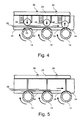
- FIG. 4 shows a sectional view taken along line IV—IV in FIG. 2, but with the imbricated flow of printed products in a further advanced position;
- FIG. 5 shows a sectional view corresponding to FIG. 4, where the guide elements do not comprise any pressure means.
- the roller table illustrated in FIG. 1 is indicated in its entirety by reference numeral 10 and is provided, on each of its two sides, with mounting supports 12 between which rollers 14 are arranged one behind the other.
- the rollers 14 are provided with a stainless-steel jacket and are driven, in the illustrated embodiment, by a drive unit not shown in detail in FIG. 1 .
- the rollers 10 may, however, as well be driven either not at all or only in part. Further, it is also possible to give the roller table 10 an inclined structure so that an imbricated flow of printed products to be transported will move across the rollers 10 solely under the influence of gravity, thereby causing the rollers to rotate.
- Clamping rails 16 which have their ends mounted on the mounting supports 12 , extend in parallel to the rollers 14 at the upper and the lower ends of the roller table 10 .
- Two diverting devices 20 and 22 are mounted on the clamping rails 16 , by means of clamping screws 18 , in a manner such that the position of the diverting devices 20 and 22 above the roller table 10 can be varied after the clamping screws 18 have been untightened.
- the ends of the diverting devices 20 and 22 are displaced longitudinally above the clamping rails 16 , in the direction indicated by arrows 24 , and are then fixed again in the desired position by re-tightening the clamping screws 18 .
- the diverting device 20 consists essentially of an elongated adjustment member 32 , composed of two bars 28 and 30 , and a number of guide elements 34 held thereon.
- the upper surface, facing the viewer, of each of the guide elements 34 is provided with a journal 36 that projects into a gap formed between the bars 28 and 30 .
- the guide elements can be displaced along the adjustment member 32 .
- the bottom faces of the guide elements 34 rest on the rollers 14 .
- the adjustment member 32 has a mere guiding function, not a carrying function, with respect to the guide elements 34 .
- reference numeral 38 indicates an imbricated flow of printed products, it being supposed that this flow is initially fed to the roller table 10 in the direction indicated by arrow 40 .
- the forward edge of the flow 38 will eventually hit against the first guide element 34 of the diverting device 20 and will be diverted by the latter to the right, viewed in the direction of movement 40 .
- the flow 38 then continues to move in the direction indicated by arrow 42 along the diverting device 20 .
- the flow 38 is subjected to a torque that tends to turn the flow 38 back to its original direction of movement 40 .
- the flow 38 returns to its original direction of movement 40 after it has passed the last guide element 34 at the end of the diverting device 20 . This is indicated by the flow with reference numeral 44 at the lower end of the roller table 10 .
- the second diverting device 22 is designed in the same way as the diverting device 20 , but is mounted in a different position above the roller table 10 .
- the guide elements 34 are always located above the rollers 14 in this different position, too.
- the distance between the journals 36 is greater in this different position than in the case of the diverting device 20 .
- the angle between the guide elements 34 and the adjustment member 32 is larger with the diverting device 22 than in the case of the diverting device 20 .
- the lateral surfaces of the guide elements 34 acting as stops, are aligned in that position so that one lateral edge of the imbricated flow of printed products 38 is in planar contact with those surfaces.
- the diverting device 22 is shown in its extreme position, where the angle between the diverting device and the direction of movement 40 defined by the rollers 14 is at its maximum. If the adjustment members 32 were inclined still further, the guide elements 34 would get displaced one relative to the other to such a degree that projections would be produced that would stop the movement of the flow 46 .
- FIG. 2 shows an enlarged view of a detail of the roller table 10 .
- Each of the guide elements 34 is provided with pressure means which have been omitted in FIG. 1 for the sake of clarity.
- the pressure means comprise balls 48 that are retained in rings 50 .
- the rings 50 are mounted on the guide elements 34 by means of screws 52 .
- the own weight of the balls 48 presses an imbricated flow of printed products 38 , guided by the guide elements 34 , against the rollers 14 from above. Given the fact that the balls 48 are permitted to move in vertical direction in the ring 50 , a constant contact pressure can be achieved even with imbricated flows of different thickness.
- Arrows 54 in FIG. 2 indicate the directions in which the guide elements 34 are permitted to move as a result of the journals 36 being guided between the bars 28 and 30 .
- FIG. 3 shows a perspective view of a guide element 34 with a journal 36 and a ring 50 .
- Two partially cylindrical recesses 56 provided one opposite the other in the bottom surface of the guide element 34 , form between them a web 58 .
- the guide elements 34 rest on the rollers 14 via the partially cylindrical surfaces formed by the recesses 56 so that each of the webs 58 comes to extend into the clearance between two neighboring rollers 14 .
- the arrangement of the guide elements 34 one relative to the other is such that only a narrow gap is left between the two parallel lateral surfaces 59 of the guide elements 34 , as indicated in FIG. 2 .
- the guide elements 34 may, however, be arranged along the adjustment member 32 so tightly together that the lateral surfaces 59 of neighboring guide elements 34 are in sliding contact one relative to the other.
- FIG. 5 shows a corresponding sectional view, but without the pressure means.
- FIGS. 4 and 5 illustrate the planar contact between the partially cylindrical surfaces of the guide elements 34 and the outer surfaces of the rollers 14 in the area of the recesses 56 .
- the area between the recesses 56 extends so deeply into the space between two neighboring rollers that it comes to lie under the bottom surface of the imbricated flow of printed products.
- the guide elements 34 are made from a nylon-like plastic material, such as POM.
- FIG. 4 shows how the imbricated flow of printed products 38 is pressed down by the balls 48 against the rollers 14 .
- each ball 48 rests on the apex of the respective roller 14 . This condition is shown at the extreme right in FIG. 4 .
- the imbricated flow 38 then automatically lifts the balls 48 as necessary, so that flows of printed products of different thickness can be pressed against the rollers 14 by the balls 48 at uniform pressure.
- the adjustment members 32 may be provided with a curvature that increases progressively in the transport direction. This helps prevent the imbricated flow from hitting hard against the first guide element 34 , especially in cases where the flow is to be diverted by a large angle.
Landscapes
- Engineering & Computer Science (AREA)
- Mechanical Engineering (AREA)
- Separation, Sorting, Adjustment, Or Bending Of Sheets To Be Conveyed (AREA)
- Delivering By Means Of Belts And Rollers (AREA)
- Registering, Tensioning, Guiding Webs, And Rollers Therefor (AREA)
Applications Claiming Priority (4)
| Application Number | Priority Date | Filing Date | Title |
|---|---|---|---|
| DE19960347A DE19960347C2 (de) | 1999-12-14 | 1999-12-14 | Vorrichtung zum Ablenken eines Schuppenstroms auf einem Rolltisch |
| DE19960347 | 1999-12-14 | ||
| DE19960347.2 | 1999-12-14 | ||
| PCT/EP2000/012572 WO2001044090A2 (fr) | 1999-12-14 | 2000-12-12 | Dispositif permettant de devier un courant lamellaire sur une table a rouleaux |
Publications (2)
| Publication Number | Publication Date |
|---|---|
| US20030020233A1 US20030020233A1 (en) | 2003-01-30 |
| US6715754B2 true US6715754B2 (en) | 2004-04-06 |
Family
ID=7932666
Family Applications (1)
| Application Number | Title | Priority Date | Filing Date |
|---|---|---|---|
| US10/149,941 Expired - Lifetime US6715754B2 (en) | 1999-12-14 | 2000-12-12 | Device for deviating an overlapping stream on a roller table |
Country Status (4)
| Country | Link |
|---|---|
| US (1) | US6715754B2 (fr) |
| EP (1) | EP1237805B1 (fr) |
| DE (2) | DE19960347C2 (fr) |
| WO (1) | WO2001044090A2 (fr) |
Cited By (1)
| Publication number | Priority date | Publication date | Assignee | Title |
|---|---|---|---|---|
| US20070234763A1 (en) * | 2004-10-16 | 2007-10-11 | Saurer Gmbh & Co. Kg | Device for the steam treatment of a moving fiber strand |
Families Citing this family (2)
| Publication number | Priority date | Publication date | Assignee | Title |
|---|---|---|---|---|
| DE19960347C2 (de) | 1999-12-14 | 2001-11-22 | Palamides Gmbh | Vorrichtung zum Ablenken eines Schuppenstroms auf einem Rolltisch |
| CN109896314A (zh) * | 2019-04-01 | 2019-06-18 | 东莞市奥奇包装机械有限公司 | 一种折页机的送纸导向校正机构 |
Citations (26)
| Publication number | Priority date | Publication date | Assignee | Title |
|---|---|---|---|---|
| US2528106A (en) | 1947-01-09 | 1950-10-31 | Hoe & Co R | Sheet registering mechanism |
| US2726751A (en) * | 1951-09-25 | 1955-12-13 | Borg Warner | Transfer mechanism |
| US2818954A (en) * | 1954-04-23 | 1958-01-07 | Armco Steel Corp | Side guide for conveyors |
| US3045792A (en) * | 1958-08-12 | 1962-07-24 | Nelson P Greller | Switching unit |
| US3091322A (en) * | 1959-07-09 | 1963-05-28 | Control Design And Fabricate I | Conveyor junction regulating mechanism |
| US3512638A (en) * | 1968-07-05 | 1970-05-19 | Gen Electric | High speed conveyor sorting device |
| US3800696A (en) * | 1971-10-22 | 1974-04-02 | Hitachi Shipbuilding Eng Co | Apparatus for marking moving bars such as steel rails |
| US3881721A (en) * | 1974-01-28 | 1975-05-06 | Molins Machine Co Inc | Sheet take off apparatus |
| US3912062A (en) * | 1974-05-20 | 1975-10-14 | Jesse B Hutchinson | Switching means for conveyor system and method of manufacture |
| US3912258A (en) * | 1972-07-28 | 1975-10-14 | Merrill David Martin | Conveyor system for conveying sheets |
| US4014539A (en) * | 1975-08-14 | 1977-03-29 | Addressograph Multigraph Corporation | Angular path sheet conveying |
| GB2080754A (en) | 1980-07-25 | 1982-02-10 | Hermann Heinz | Apparatus for orienting and loading flat bags into a container |
| JPS5793805A (en) * | 1980-12-02 | 1982-06-11 | Toyo Tire & Rubber Co Ltd | Branching device of gravity roller conveyer |
| JPS63127952A (ja) * | 1986-11-14 | 1988-05-31 | Fujitsu Ltd | 媒体搬送機構 |
| DE3926608A1 (de) | 1988-08-29 | 1990-03-01 | Polygraph Leipzig | Foerder- und ausrichtetisch fuer bogen aus papier |
| US5004220A (en) * | 1985-07-13 | 1991-04-02 | Bell & Howell Gmbh | Method and apparatus for changing the direction of sheet conveyance |
| US5027939A (en) * | 1990-01-24 | 1991-07-02 | Alvey Inc. | Sorting conveyor system |
| JPH04101912A (ja) | 1990-08-16 | 1992-04-03 | Toto Ltd | 三方向分岐合流コンベア及び製造コンベアライン |
| US5238164A (en) * | 1992-07-29 | 1993-08-24 | Moore Business Forms, Inc. | Offset conveyor |
| EP0581050A1 (fr) * | 1992-07-28 | 1994-02-02 | Mathias Bäuerle GmbH | Dispositif de transport d'une feuille de papier ou similaire |
| WO1994013566A1 (fr) | 1992-12-04 | 1994-06-23 | Grapha-Holding Ag | Installation pour le transfert d'un flux de nappes constitue de produits imprimes |
| FR2743549A1 (fr) | 1996-01-17 | 1997-07-18 | Sempag Sa | Dispositif de rectification de flots de flans predecoupes a assembler en ecailles |
| US5971132A (en) * | 1997-06-18 | 1999-10-26 | United Parcel Service Of America, Inc. | High speed automated cog sorter |
| US6223887B1 (en) * | 1997-11-21 | 2001-05-01 | Daifuku Co., Ltd. | Device for Transferring Products |
| DE19960347C2 (de) | 1999-12-14 | 2001-11-22 | Palamides Gmbh | Vorrichtung zum Ablenken eines Schuppenstroms auf einem Rolltisch |
| US6481559B1 (en) * | 1998-08-03 | 2002-11-19 | Hiromu Maeda | Transfer and sorting conveyor |
Family Cites Families (1)
| Publication number | Priority date | Publication date | Assignee | Title |
|---|---|---|---|---|
| DE3026608A1 (de) * | 1980-07-14 | 1982-10-21 | Siemens AG, 1000 Berlin und 8000 München | Flachbildroehre |
-
1999
- 1999-12-14 DE DE19960347A patent/DE19960347C2/de not_active Expired - Fee Related
-
2000
- 2000-12-12 US US10/149,941 patent/US6715754B2/en not_active Expired - Lifetime
- 2000-12-12 EP EP00993400A patent/EP1237805B1/fr not_active Expired - Lifetime
- 2000-12-12 WO PCT/EP2000/012572 patent/WO2001044090A2/fr not_active Ceased
- 2000-12-12 DE DE50006535T patent/DE50006535D1/de not_active Expired - Lifetime
Patent Citations (27)
| Publication number | Priority date | Publication date | Assignee | Title |
|---|---|---|---|---|
| US2528106A (en) | 1947-01-09 | 1950-10-31 | Hoe & Co R | Sheet registering mechanism |
| US2726751A (en) * | 1951-09-25 | 1955-12-13 | Borg Warner | Transfer mechanism |
| US2818954A (en) * | 1954-04-23 | 1958-01-07 | Armco Steel Corp | Side guide for conveyors |
| US3045792A (en) * | 1958-08-12 | 1962-07-24 | Nelson P Greller | Switching unit |
| US3091322A (en) * | 1959-07-09 | 1963-05-28 | Control Design And Fabricate I | Conveyor junction regulating mechanism |
| US3512638A (en) * | 1968-07-05 | 1970-05-19 | Gen Electric | High speed conveyor sorting device |
| US3800696A (en) * | 1971-10-22 | 1974-04-02 | Hitachi Shipbuilding Eng Co | Apparatus for marking moving bars such as steel rails |
| US3912258A (en) * | 1972-07-28 | 1975-10-14 | Merrill David Martin | Conveyor system for conveying sheets |
| US3881721A (en) * | 1974-01-28 | 1975-05-06 | Molins Machine Co Inc | Sheet take off apparatus |
| US3912062A (en) * | 1974-05-20 | 1975-10-14 | Jesse B Hutchinson | Switching means for conveyor system and method of manufacture |
| US4014539A (en) * | 1975-08-14 | 1977-03-29 | Addressograph Multigraph Corporation | Angular path sheet conveying |
| GB2080754A (en) | 1980-07-25 | 1982-02-10 | Hermann Heinz | Apparatus for orienting and loading flat bags into a container |
| JPS5793805A (en) * | 1980-12-02 | 1982-06-11 | Toyo Tire & Rubber Co Ltd | Branching device of gravity roller conveyer |
| US5004220A (en) * | 1985-07-13 | 1991-04-02 | Bell & Howell Gmbh | Method and apparatus for changing the direction of sheet conveyance |
| JPS63127952A (ja) * | 1986-11-14 | 1988-05-31 | Fujitsu Ltd | 媒体搬送機構 |
| DE3926608A1 (de) | 1988-08-29 | 1990-03-01 | Polygraph Leipzig | Foerder- und ausrichtetisch fuer bogen aus papier |
| US5027939A (en) * | 1990-01-24 | 1991-07-02 | Alvey Inc. | Sorting conveyor system |
| JPH04101912A (ja) | 1990-08-16 | 1992-04-03 | Toto Ltd | 三方向分岐合流コンベア及び製造コンベアライン |
| EP0581050A1 (fr) * | 1992-07-28 | 1994-02-02 | Mathias Bäuerle GmbH | Dispositif de transport d'une feuille de papier ou similaire |
| US5238164A (en) * | 1992-07-29 | 1993-08-24 | Moore Business Forms, Inc. | Offset conveyor |
| WO1994013566A1 (fr) | 1992-12-04 | 1994-06-23 | Grapha-Holding Ag | Installation pour le transfert d'un flux de nappes constitue de produits imprimes |
| US5503386A (en) | 1992-12-04 | 1996-04-02 | Grapha-Holding Ag | Device for transferring a scale-shaped flow consisting of printed products |
| FR2743549A1 (fr) | 1996-01-17 | 1997-07-18 | Sempag Sa | Dispositif de rectification de flots de flans predecoupes a assembler en ecailles |
| US5971132A (en) * | 1997-06-18 | 1999-10-26 | United Parcel Service Of America, Inc. | High speed automated cog sorter |
| US6223887B1 (en) * | 1997-11-21 | 2001-05-01 | Daifuku Co., Ltd. | Device for Transferring Products |
| US6481559B1 (en) * | 1998-08-03 | 2002-11-19 | Hiromu Maeda | Transfer and sorting conveyor |
| DE19960347C2 (de) | 1999-12-14 | 2001-11-22 | Palamides Gmbh | Vorrichtung zum Ablenken eines Schuppenstroms auf einem Rolltisch |
Cited By (1)
| Publication number | Priority date | Publication date | Assignee | Title |
|---|---|---|---|---|
| US20070234763A1 (en) * | 2004-10-16 | 2007-10-11 | Saurer Gmbh & Co. Kg | Device for the steam treatment of a moving fiber strand |
Also Published As
| Publication number | Publication date |
|---|---|
| WO2001044090A2 (fr) | 2001-06-21 |
| EP1237805A2 (fr) | 2002-09-11 |
| DE50006535D1 (de) | 2004-06-24 |
| EP1237805B1 (fr) | 2004-05-19 |
| WO2001044090A3 (fr) | 2002-05-10 |
| US20030020233A1 (en) | 2003-01-30 |
| DE19960347A1 (de) | 2001-07-12 |
| DE19960347C2 (de) | 2001-11-22 |
Similar Documents
| Publication | Publication Date | Title |
|---|---|---|
| US8196736B2 (en) | Roller arrangement for conveyor | |
| US6343685B1 (en) | Apparatus for conveying sheet-like articles | |
| US5584373A (en) | Conveyor system with passive roller transfer assembly | |
| US5342040A (en) | Turning device for sheets of paper in a feed web | |
| JP2009001429A (ja) | 物品の流れの方向を転換するための装置 | |
| US5551551A (en) | Article combiner with multiple conveying surfaces and moving guides | |
| US20080191409A1 (en) | Diverting flat belt support system | |
| US6533271B1 (en) | Switch point for flat, flexible postal articles in sorting machines | |
| CN107922123A (zh) | 具有缓冲辊的输送机引导壁 | |
| ITMI971601A1 (it) | Parete divisoria per l'installazione al di sopra di un nastro di trasporto di articoli quali bottiglie e simili | |
| RU2356822C2 (ru) | Устройство для поперечной транспортировки стоп | |
| US6715754B2 (en) | Device for deviating an overlapping stream on a roller table | |
| SI9200173B (sl) | Priprava za nanašanje runa, zlasti runa iz mineralne volne, na nalagalni trak. | |
| EP1060111A1 (fr) | Tapis transporteur en courbe | |
| US7775346B1 (en) | Food buffet table system | |
| GB2189758A (en) | A feed bench for feeding articles on to a main conveyor belt at an angle thereto | |
| US3550741A (en) | Conveyor for paper sheets and the like | |
| KR910021309A (ko) | 용지 배출 장치 | |
| CA2377736C (fr) | Dispositif de transport d'objets plats avec un systeme d'acheminement | |
| JP3583139B2 (ja) | 平らな発送物の搬送装置 | |
| CN211945266U (zh) | 一种包裹分离系统 | |
| CA2092624C (fr) | Table de marge | |
| JP6369256B2 (ja) | 分岐コンベヤ | |
| US20100230253A1 (en) | Continuous Conveyor Belt | |
| US20050006838A1 (en) | Device for centering an overlapping sheet flow |
Legal Events
| Date | Code | Title | Description |
|---|---|---|---|
| AS | Assignment |
Owner name: PALAMIDES GMBH, GERMANY Free format text: ASSIGNMENT OF ASSIGNORS INTEREST;ASSIGNORS:PALAMIDES, STEFANO;PFEIFFER, WOLFGANG;OLDENKOTT, JOHANNES;AND OTHERS;REEL/FRAME:013548/0129;SIGNING DATES FROM 20020626 TO 20020627 |
|
| STCF | Information on status: patent grant |
Free format text: PATENTED CASE |
|
| CC | Certificate of correction | ||
| FPAY | Fee payment |
Year of fee payment: 4 |
|
| FPAY | Fee payment |
Year of fee payment: 8 |
|
| FPAY | Fee payment |
Year of fee payment: 12 |