US6710327B2 - Multi-fiber multi-cylinder position method and apparatus using time-of-flight technique - Google Patents
Multi-fiber multi-cylinder position method and apparatus using time-of-flight technique Download PDFInfo
- Publication number
- US6710327B2 US6710327B2 US09/872,895 US87289501A US6710327B2 US 6710327 B2 US6710327 B2 US 6710327B2 US 87289501 A US87289501 A US 87289501A US 6710327 B2 US6710327 B2 US 6710327B2
- Authority
- US
- United States
- Prior art keywords
- pulse
- laser light
- cylinder
- photodiode
- circuit
- Prior art date
- Legal status (The legal status is an assumption and is not a legal conclusion. Google has not performed a legal analysis and makes no representation as to the accuracy of the status listed.)
- Expired - Lifetime, expires
Links
Images


Classifications
-
- F—MECHANICAL ENGINEERING; LIGHTING; HEATING; WEAPONS; BLASTING
- F15—FLUID-PRESSURE ACTUATORS; HYDRAULICS OR PNEUMATICS IN GENERAL
- F15B—SYSTEMS ACTING BY MEANS OF FLUIDS IN GENERAL; FLUID-PRESSURE ACTUATORS, e.g. SERVOMOTORS; DETAILS OF FLUID-PRESSURE SYSTEMS, NOT OTHERWISE PROVIDED FOR
- F15B15/00—Fluid-actuated devices for displacing a member from one position to another; Gearing associated therewith
- F15B15/20—Other details, e.g. assembly with regulating devices
- F15B15/28—Means for indicating the position, e.g. end of stroke
- F15B15/2815—Position sensing, i.e. means for continuous measurement of position, e.g. LVDT
- F15B15/2869—Position sensing, i.e. means for continuous measurement of position, e.g. LVDT using electromagnetic radiation, e.g. radar or microwaves
- F15B15/2876—Position sensing, i.e. means for continuous measurement of position, e.g. LVDT using electromagnetic radiation, e.g. radar or microwaves using optical means, e.g. laser
Definitions
- the invention relates generally to position sensing of hydraulic and pneumatic actuators. More particularly, it relates to sensing using laser light sources and detectors and determining the position of the actuator using time-of-flight algorithms.
- Position sensing for hydraulic or pneumatic actuators typically uses an external position sensor, such as a rotary rheostat or potentiometer. Alternatively, linear rheostats or variable differential transformers are employed. These systems suffer from poor accuracy, extensive wear, and fragility in many applications, especially demanding applications such as their use on work and agricultural vehicles.
- the microwave transmitter suffers from high cost and difficulties in determining which of the many reflections in the cylinder is the proper one to measure.
- the pulse generating and timing circuits of U.S. Pat. No. 6,005,395 are used, but are coupled to a laser light source and respond to a reflection of that beam against a laser light detector, such as that shown in co-pending U.S. patent application Ser. No. 09/750,866.
- This arrangement also has drawbacks.
- the piston moves toward or away from the source and detector, the reflected light follows multiple paths that, like the microwave transmitter and receiver pair, make the reflected pulses difficult to interpret. It is difficult to extract a good pulse indicative the precise time-of-flight of the laser beam.
- a single optical fiber transmits laser-light pulses from outside a hydraulic or pneumatic cylinder to inside the cylinder.
- the fiber is preferably located along a central longitudinal axis of the cylinder.
- the light pulses from the transmitting fiber travel down the cylinder substantially parallel to the longitudinal axis of the cylinder and reflect off the face of the piston in the cylinder. The light is reflected straight back toward the transmitting fiber.
- the path it follows in returning to the transmitting fiber at the end of the cylinder is substantially the same path as the path it traveled when going from the fiber to the piston.
- the laser beam is preferably normal to the piston where it is reflected in order to provide these parallel in and out paths.
- the laser light pulses return to the region of the transmitting fiber, they fall on the free ends of several optical fibers disposed around the central transmitting fiber. All of these fibers receive the light pulses at substantially the same time and conduct the light pulse from inside the cylinder to outside the cylinder.
- the receiving fibers are closely spaced in a circular arrangement equidistant from the central fiber. Since the light pulse from the central fiber follows the same path back after reflecting from the piston, each of the fibers receives approximately the same amount of light energy, and receives it at almost exactly the same time.
- the distal ends of the receiving fibers are coupled together such that each portion of the reflected light pulse that each individual fiber of the receiving fiber carries are merged to form a much stronger light pulse.
- the lengths of the receiving optical fibers are chosen such that the portions of the reflected light pulse that each one carries is merged into a single pulse at exactly the same time. This sharply increases the magnitude of the resulting pulse and provides an extremely fast and sharp rise time. In this manner, a reflected light pulse can be “reassembled” with a very sharp leading edge that permits precise time-of-flight measurements.
- a multiple cylinder position sensing system includes a first cylinder including a first source light guide having a first end and a distal second end and extending from inside the cylinder to outside the cylinder and adapted to transmit at least a first beam of laser light at a first frequency from outside the cylinder to inside the cylinder, and at least one first reflected light guide having a first end and a distal second end and extending from inside the cylinder to outside the cylinder and configured to receive light from the first beam of laser light that is reflected off the inside of the first cylinder, and a second cylinder including a second source light guide having a first end and a distal second end and extending from inside the cylinder to outside the cylinder and adapted to transmit at least a second beam of laser light at a first frequency from outside the cylinder to inside the cylinder, and at least one second reflected light guide having a first end and a second end and extending from inside the cylinder to outside the cylinder and configured to receive
- the system may include a laser light source that is optically coupled to the distal ends of both the first and second source light guides, and configured to generate a source beam of laser light, wherein the source beam is divided into the first and second beams of laser light.
- the system may include a first photodiode configured to receive and electrically respond to light from the first beam of laser light that is reflected off the inside of the first cylinder from the first reflected light guide.
- the system may also include a laser light source driver circuit coupled to the laser light source and configured to energize the laser light source upon receipt of a trigger pulse, and a timing circuit coupled to the laser light source driver configured to generate the trigger pulse and apply the trigger pulse to the laser light source driver circuit.
- the laser light source may be a laser diode.
- the system may include first and second photodiode amplifiers that are coupled to the first and second photodiodes, respectively.
- Each of the first and second photodiode amplifiers may be configured to generate an output signal.
- the system may also include a pulse expansion circuit, to which the first and second photodiode output signals are coupled.
- the second ends of the plurality of second light guides may be optically coupled to a single light detector.
- the light detector may have an electrical output that is produced by light carried by at least two of the plurality of second light guides.
- a method for determining the time-of-flight of laser light pulses in a plurality of hydraulic or pneumatic cylinders including the steps of generating a timing pulse in a timing circuit, conducting the timing pulse to a laser light source and responsively generating laser light pulse from the source, conducting a first portion of the pulse through a first optical fiber to a first cylinder, conducting the first portion into the first cylinder, reflecting the first portion off a first reflective surface coupled to a first piston in the first cylinder, receiving the first portion at a first photo diode and responsively generating a first electrical signal, conducting a second portion of the pulse through a second optical fiber to a second cylinder, conducting the second portion into the second cylinder, reflecting a second portion off a second reflective surface coupled to a second piston in the second cylinder, receiving the second portion at a second photo diode and suppressing the generation of the second electrical signal, providing the first electrical signal and the timing pulse to a comparator circuit and responsibly
- the method may also include the steps of generating a second timing pulse in the timing circuit, conducting the second pulse to the laser light source and responsibly generating a second laser light pulse from the source, conducting a first portion of the second laser light pulse through the first optical fiber to the first cylinder, conducting the first portion of the second laser light pulse into the first cylinder, reflecting the first portion of the second laser light pulse off the first reflective surface, receiving the first portion of the second laser light pulse at the first photo diode and suppressing the generation of a third electrical signal indicative of the time of arrival of the first portion of the second laser light pulse at the first photo diode, conducting a second portion of the second laser light pulse through the second optical fiber to the second cylinder, conducting the second portion of the second laser light pulse into the second cylinder, reflecting the second portion of the second laser light pulse off the second reflective surface, receiving the second portion of the second laser light pulse at a second photo diode and responsibly generating a fourth electrical signal indicative of the time of arrival of the second portion of the second laser light pulse at the second photo diode,
- the step of conducting the first timing pulse to the laser light source and responsively generating a second laser light pulse from the source may include the steps of optically coupling the laser light source to distal ends of the first and second optical fibers, and dividing the first laser light pulse into the first and second portions.
- the method may also include the steps of providing a laser light source driver circuit, coupling the laser light source to the driver circuit, applying the first and second timing pulses to the laser light source driver circuit, and energizing the laser light source responsive to the application of the first and second timing pulses to the driver circuit.
- the method may include the steps of providing a first photo diode amplifier and coupling the first photo diode amplifier to the first photo diode, providing a second photo diode amplifier and coupling the second photo diode amplifier to the second photo diode, generating a first gate signal in the timing circuit, applying the first gate signal to the first photo diode amplifier to permit the transmission of first electrical signal, generating a second gate signal in the timing circuit, and applying the second gate signal to the second photo diode amplifier to suppress the transmission of the second electrical signal.
- the method may include the step of configuring the first and second photo diode amplifiers to generate first and second amplifier output signals, respectively.
- the method may include the step of coupling the first and second photo diode amplifier output signals and transmitting the coupled output signals to a pulse expansion circuit.
- the method may include the step of transmitting the first and second output signals to a pulse expansion circuit.
- the method may include the steps of generating an expanded pulse output signal in the pulse expansion circuit, and outputting the expanded pulse output signal from the pulse expansion circuit.
- the method may include the steps of providing a pulse comparator circuit, and inputting the expanded pulse output signal and the timing pulse into the pulse comparator circuit, and generating a time delay output signal in the pulse comparator circuit indicative of a time delay between the timing pulse and the expanded pulse output signal.
- a method of determining the time-of-flight of laser light in a plurality of hydraulic or pneumatic cylinders includes the steps of transmitting a laser light pulse from a laser diode, dividing the laser light pulse into at least first and second sub-pulses, injecting the first and second sub-pulses into first and second cylinders, respectively, reflecting the first and second sub-pulses off first and second pistons in the first and second cylinders, respectively, transmitting the first and second reflected sub-pulses at two first and second photo diodes, respectively, generating first and second electrical signals in the first and second photo diodes that are indicative of the first and second times of arrival of the first and second sub-pulses at the first and second photo diodes, respectively, selectively coupling the first and second electrical signals in a first mode of operation to a pulse expansion circuit and a phase comparator circuit to generate a first time-of-flight signal on an output line of the phase comparator circuit that is indicative of the time-of
- FIG. 1 is a partial cross-sectional view of a hydraulic actuator having the laser-based reflective beam sensor and a control unit for generating the laser beam and calculating the position of the actuator wherein the laser light sources are located remotely from the actuator and cables including three fiber optic light guides couple the control unit to the actuator;
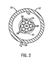
- FIG. 2 is a partial cross-sectional view of the embodiment of FIG. 1 showing how the light guides are coupled to the cylinder;
- FIG. 3 is graph of laser light transmissivities through several different hydraulic fluids of various ages and types.
- FIG. 4 illustrates an arrangement that includes several cylinders that are multiplexed together sharing common circuitry in accordance with the present invention.
- FIG. 1 is a schematic view of a linear cylindrical actuator 10 in accordance with the present invention.
- Actuator 10 includes a cylinder 12 having an inner diameter 14 and two end caps 16 , 18 .
- Rod end cap 16 encloses one longitudinal end of the cylinder and has an opening 17 through which rod 24 passes. Opening 17 seals against the surface of the rod and prevents actuating fluid from leaking out.
- End cap 18 encloses the opposing end of the cylindrical potion of the cylinder and prevents actuating fluid from leaking out.
- Actuator 10 also includes a piston assembly 20 which includes a piston 22 having an outside diameter 23 configured to seal against the inner diameter 14 of the cylinder and to slide longitudinally, back and forth, with respect to cylinder 12 .
- Piston 22 is coupled to rod 24 , which extends from the inside of the cylinder to the outside of the cylinder through opening 17 and is fixed to piston 22 to move simultaneously with the piston.
- Surface 26 is a reflective surface fixed to move with piston 22 and is configured to reflect laser light that is introduced into the cylinder.
- Two ports 28 , 30 are provided in the cylinder to introduce an operating fluid into the cylinder or remove the operating fluid from the cylinder.
- Extension cylinder port 28 is disposed in the cylinder such that fluid introduced into the port will cause the piston and piston rod to move in a direction that increases the overall length of the actuator 10 .
- Retraction cylinder port 30 is disposed in the cylinder such that when a working fluid is introduced into the actuator through this port, it causes the piston assembly to move into the cylinder, or retract, thereby reducing the overall length of actuator 10 .
- rod 24 extends farther outside the cylinder, increasing the overall length of actuator 10 .
- the cylinder and piston assembly collectively define two internal cavities separated by the piston into which fluid may be introduced or removed.
- Extension cavity 32 when filled (through port 28 ) causes the piston assembly to extend, increasing the overall length of the actuator. At the same time, retraction cavity 34 is emptied. Similarly, when retraction cavity 34 is filled, through retraction cylinder port 30 , retraction cavity 34 fills with fluid, extension cavity 32 empties fluid through extension cylinder port 28 .
- actuator 10 has a predetermined internal fluid volume that does not change based upon the position of the piston. This volume (again, discarding the effects due to the size of piston rod 24 ) is equal to the sum of the volumes of extension cavity 32 and retraction cavity 34 .
- An optical coupler 34 is fixed in end cap 18 to communicate laser light into chamber 32 and to communicate laser light from chamber 32 outside the cylinder.
- the cap itself has a threaded external surface that engages mating threads in end cap 18 . These threads serve to secure the coupler to the end cap and to prevent leakage of hydraulic fluid or air out of the cylinder.
- the coupler also serves to hold several optical fibers 36 , 38 in a fixed relationship with respect to cylinder 12 .
- Coupler 34 is preferably disposed along the centerline of cylinder 12 such that the cylinder and the coupler share a common cylindrical axis 40 . Referring now to FIG.
- coupler 34 supports eight optical fibers ranged in arcuate, preferably circular, pattern equidistantly spaced from the longitudinal cylindrical axis of the coupler. These fibers gather light that is reflected off surface 26 and conduct it out of the cylinder.
- Fiber 36 is disposed along axis 40 and conducts light from outside the cylinder into the cylinder. Light that is conducted into the cylinder through fiber 36 is directed towards reflective surface 26 on piston 22 . It reflects off piston 22 and returns in a plurality of paths to each of optical fibers 38 . These fibers receive the light at substantially the same time and conduct the light out of the cylinder.
- An optical combiner 42 is optically coupled to fibers 38 and joins their/there individual light beams into a single beam that exits combiner 42 in optical fiber 44 .
- the light carried by optical coupler 44 is the combination of all the individual beams of light carried by optical fibers 38 .
- optical fiber 44 is at its other end connected to optical coupler 46 , which directs and focuses the light beam of fiber 44 to photodiode 48 .
- optical coupler 46 which directs and focuses the light beam of fiber 44 to photodiode 48 .
- photodiode amplifier 52 When the light passes through coupler 46 and falls upon photodiode 48 , it changes the conductivity of the photodiode causing a change in the current flowing through circuit 50 .
- This change in current, or photodiode signal is amplified by photodiode amplifier 52 .
- the output of photodiode amplifier 52 is fed to pulse expansion circuit 54 which increases the width of the photodiode signal.
- Phase comparison circuit 56 receives two impulses: the expanded pulse from pulse expansion circuit 54 and a trigger pulse from timing circuit 58 . By determining the time difference between the pulse of timing circuit 58 and the expanded pulse from circuit 54 , phase comparison circuit 56 generates a signal indicative of the time delay between these two pulses. This
- Timing circuit 58 generates periodic pulses on the order of once every tenth of a second. These two pulses are provided on two signal lines. Signal line 62 , which goes to phase comparison circuit 56 and signal line 64 , which goes to laser driver circuit 66 . Laser driver circuit 66 , when it receives this timing signal, generates a pulse that is applied to laser diode 68 . Laser diode 68 turns the signal into a laser light pulse, which is transmitted through optical fiber 36 and coupler 34 into cylinder 12 . The laser light pulse traverses cavity 32 , reflects off surface 26 and returns to optical fibers 38 , which are held in coupler 34 .
- circuit 56 receives a pulse on line 62 generated by timing circuit 58 . It also receives an expanded pulse from pulse expansion circuit 54 . The difference in time of arrival of these two pulses is substantially equal to the amount of time it takes for the laser light pulse to travel from laser diode 68 to photodiode 48 . Whenever piston 20 moves, both the path from laser diode 68 to the piston increases and the path from the piston to photodiode 48 increases. Since this is a linear device, for every inch of movement of piston 20 the path length changes by two inches.
- Pulse expansion circuit 54 is disclosed in more detail in U.S. Pat. No. 6,005,395 as the directional sampler 74 .
- the output of pulse expansion circuit 54 is an equivalent-time replica of the reflected pulses received by photodiode 48 .
- Phase comparison circuit 56 is described in U.S. Pat. No. 6,005,395 as directional set/reset circuit 100 .
- the output signal 60 is preferably in the form of a square wave having a pulse width indicative of the time required for the light emitted from laser diode 68 to travel through the system. Changes in the pulse width are preferably proportional to the distance the piston has traveled.
- Coupler 34 is fixed to optical fibers 38 that transmit the reflected light beam out of the cylinder.
- Coupler 34 is preferably disposed within the cylinder, as shown in FIG. 2, such that fiber 38 enters the cylinder substantially coaxial with longitudinal axis 40 of the cylinder.
- Each of the eight fibers 38 is preferably disposed equidistantly with respect to fiber 38 and is preferably spaced equidistantly apart from the others of fibers 38 . In this manner, each fiber has a corresponding fiber disposed on the opposing side of optical fiber 38 from which they are both equally spaced.
- each of the optical fibers 38 and optical fiber 36 are preferably parallel such that light transmitted into the cylinder through optical fiber 36 will reflect off surface 26 of piston 20 and return directly to coupler 34 . If surface 26 is disposed in a substantially perpendicular orientation with respect to the longitudinal axes of fibers 38 and 36 , substantially all the light that is emitted into cylinder 12 by optical fiber 36 will arrive back at coupler 34 .
- optical fibers for receiving reflected light are two fold. First, a smaller diameter optical fiber can be spaced closer to fiber 36 . This closer spacing means that it is in a better position to receive the reflected light that reflects off perpendicular reflective surface 26 . Secondly, by providing several optical fibers, considerably more reflected light can be gathered and provided to photodiode 48 . This provides a substantially larger pulse and reduces any the possibility that stray reflections will trigger photodiode 48 .
- each of optical fibers 38 is preferably the same length. Thus, when reflected light is received substantially simultaneously at each of the end of optical fibers 38 in cylinder 12 , these pulses will take substantially the same time to arrive at combiner 42 . Since each of fibers 38 are multiplexed together, the light in each fiber 38 will be added and inserted into optical fiber 44 . Thus, any reflected light falling simultaneously on the receiving ends of fibers 38 will be combined and arrive simultaneously at the photodiode.
- the spacing between fiber 36 and each of fiber 38 is preferably small, on the order of one to two centimeters. More preferably it is between five and ten millimeters.
- FIG. 3 is a plot of transmissivity vs. wavelength. It measures the degree to which laser light is attenuated as it passes through hydraulic fluids of varying types.
- the types of hydraulic fluid tested include “J” type fluid with in-trained air, “J” type fluid, old “E” type fluid, old “F” type fluid, and old “G” type fluid as shown in the legend in FIG. 3 . These types of hydraulic fluid are well known to engineers working with hydraulic fluids, and represent several of the most common fluids used in hydraulic systems today.
- the “E”, “F” and “G” type fluids are “old” in that the fluids tested have been used in actual hydraulic equipment, and were not new.
- ranges there are three separate sub-ranges in which a significant amount of light is transmitted. These ranges are 700-1150 nanometers, 1250-1400 nanometers, and 1450-1650 nanometers. The broadest of these three ranges is the band between 700 and 1150 nanometers. In this range, there are three significant sub-ranges in which transmissivity is substantial these include the sub-range of 700-900 nanometers, 950-1025 nanometers, and 1030-1150 nanometers. Each of these sub-bands has a local transmissivity maximum at 850, 970, and 1090 nanometers, respectively. The other two major bands have their respective maxima at 1315 nanometers and 1560 nanometers, respectively.
- the peak transmissivities in each of the bands and sub-bands do not vary substantially from the peak transmissivities of the other peak transmissivities. Comparing the “G_old” to the “E_old” fluids, although the variations in transmissivity at each of their respective maxima varies from 0.1 (at 1090 nanometers) to 0.4 (at 850 nanometers), the wavelengths of these respective maxima are the same.
- An appropriate high power laser diode for transmitting light through the hydraulic fluid would therefore be preferably selected to have a wavelength at or near any of the local maxima shown in FIG. 3 .
- an appropriate high power laser diode for transmitting light through the hydraulic fluid would therefore be preferably selected to have a wavelength at or near any of the local maxima shown in FIG. 3 .
- a laser diode having a frequency of 850, +80/ ⁇ 125 nanometers, 970+/ ⁇ 30 nanometers, or 1090+/ ⁇ 30 nanometers would be particularly preferred.
- FIG. 4 illustrates an arrangement of multiple hydraulic cylinders with laser light sensors that are connected to a single laser diode. This arrangement permits a plurality of hydraulic or pneumatic cylinders to be monitored by a single pulse expansion circuit and phase comparator circuit.
- the cylinders 10 are identical both in FIG. 1 and FIG. 4 .
- the optical couplers 34 are also identical in both FIG. 1 and FIG. 4 .
- the optical fibers and connectors extending from the cylinder to the photodiode amplifier are also identical in both figures.
- the laser driver 66 and laser diode 68 are also identical.
- Optical fiber 37 in FIG. 4 differs from optical fiber 37 in FIG.
- each of the separable sub-fibers are separated and directed to each of three fiber optic connectors 39 .
- the other end of these three optical fibers are held closely together and disposed in the optical path in front of laser diode 68 . In this manner, laser light generated by laser diode 68 is transmitted into at least three fibers at once.
- laser diode 68 When laser diode 68 generates a pulse of light, that pulse is transmitted into each of the three optical fibers that are closely coupled to the laser diode. Since the three fibers are separated and connected to individual fiber optic connectors 39 , the pulse of light travels down each of the three fibers through connectors 39 , through each of three optical fibers 36 and into all three hydraulic actuators 10 . The light pulses traverse cylinder 12 , reflect off reflective surface 26 and return to optical couplers 34 . Each of the individual fibers 38 for each of the couplers 34 receives a portion of the light, which is then merged at combiners 42 . For each of the three cylinders, the reflected pulse of laser light then travels down optical fiber 44 , through collimating lens assembly 46 and falls upon photodiode 48 .
- the light from laser diode 68 is received at three different photodiodes and three different photodiode amplifiers.
- Each pulse of light from laser diode 68 is therefore first divided into three separate optical fibers.
- the three pulses from these three fibers are reflected off a piston and the reflected pulses are then further sub-divided into two or more receiving optical fibers 38 .
- the reflected optical pulses that are gathered by two or more individual fibers 38 are gathered together again and converted into a single optical pulse (with a greater amplitude than any of the three sub-divided pulses on fibers 38 ) and is applied to a corresponding photo diode amplifier 52 ′ for that actuator.
- each photodiode amplifier 52 ′ is joined to the other outputs, which are provided to pulse expansion circuit 54 .
- the expanded pulse is then transmitted to phase comparator 56 , which then provides the time-of-flight on line 60 for further processing.
- each of the three actuators 10 will operate independently of the other.
- one piston may be very close to optical coupler 34 while another piston is far away.
- the two pistons may move towards one another, cross paths, and assume the opposite orientation, with the extended cylinder now retracted and the retracted cylinder now extended.
- pulse expansion circuit 54 simultaneously received signals from all three photodiode amplifiers whenever a pulse of light was generated by laser diode 68 , it would become impossible for it to differentiate between the three cylinders. If the optical path lengths for the three cylinders were ever equal, due to movement of pistons 20 , photodiode amplifiers 52 prime would transmit pulses at the same time. As the optical paths change their relative lengths, it would become impossible to determine, as they separated, which pulse received by pulse expansion circuit 54 corresponded to which cylinder.
- timing circuit 58 ′ is equipped to not only generate simultaneous pulses on line 62 and 64 (the lines coupled to phase comparator circuit 56 and laser driver 66 ) respectively, but also to selectively enable a single photodiode amplifier 52 ′ and disable the other photo diode amplifiers 52 ′ using one or more of gate signals: gate 1 , gate 2 , or gate 3 .
- each of photodiode amplifiers 52 ′ will not transmit a pulse to pulse expansion circuit 54 unless they receive a corresponding gate signal on their corresponding gate signal line. When they do not transmit a pulse, they are “disabled”, and vice-versa.
- timing circuit 58 ′ generates a gate pulse on one of the gate signal lines at substantially the same time as it generates the timing pulse on line 62 and 64 . If the gate signal is transmitted on gate signal line “gate 1 ” then only the pulse of light returning from the top most cylinder in FIG. 4 will be transmitted by a photodiode amplifier to the pulse expansion circuit.
- timing circuit 58 ′ can selectively enable or disable a plurality of photodiode amplifiers, thereby preventing the transmission of one or more reflected light pulses in electrical form to pulse expansion circuit 54 .
Abstract
Description
Claims (19)
Priority Applications (1)
| Application Number | Priority Date | Filing Date | Title |
|---|---|---|---|
| US09/872,895 US6710327B2 (en) | 2001-06-04 | 2001-06-04 | Multi-fiber multi-cylinder position method and apparatus using time-of-flight technique |
Applications Claiming Priority (1)
| Application Number | Priority Date | Filing Date | Title |
|---|---|---|---|
| US09/872,895 US6710327B2 (en) | 2001-06-04 | 2001-06-04 | Multi-fiber multi-cylinder position method and apparatus using time-of-flight technique |
Publications (2)
| Publication Number | Publication Date |
|---|---|
| US20020179824A1 US20020179824A1 (en) | 2002-12-05 |
| US6710327B2 true US6710327B2 (en) | 2004-03-23 |
Family
ID=25360542
Family Applications (1)
| Application Number | Title | Priority Date | Filing Date |
|---|---|---|---|
| US09/872,895 Expired - Lifetime US6710327B2 (en) | 2001-06-04 | 2001-06-04 | Multi-fiber multi-cylinder position method and apparatus using time-of-flight technique |
Country Status (1)
| Country | Link |
|---|---|
| US (1) | US6710327B2 (en) |
Cited By (9)
| Publication number | Priority date | Publication date | Assignee | Title |
|---|---|---|---|---|
| WO2007069955A1 (en) * | 2005-12-15 | 2007-06-21 | Volvo Lastvagnar Ab | Method for detecting clutch cylinder leakage |
| US8047122B1 (en) * | 2010-06-14 | 2011-11-01 | Drilling Technological Innovations | Tensioner assembly with multiple cylinder stroke system |
| US8253790B1 (en) | 2010-06-14 | 2012-08-28 | Drilling Technological Innovations, LLC | Cylinder stroke system with laser proximity detector |
| US8517110B2 (en) | 2011-05-17 | 2013-08-27 | Drilling Technology Innovations, LLC | Ram tensioner system |
| US20130265583A1 (en) * | 2012-04-06 | 2013-10-10 | Teledyne Scientific & Imaging, Llc | Fiber optic position sensing system |
| US8757204B1 (en) | 2013-11-22 | 2014-06-24 | Drilling Technological Innovations, LLC | Riser recoil valve |
| US8757205B1 (en) | 2013-11-22 | 2014-06-24 | Drilling Technological Innovations, LLC | Choke assembly tensioner system for a drilling rig |
| US20160097408A1 (en) * | 2014-10-06 | 2016-04-07 | Caterpillar Inc. | Cylinder position determination using fiber optic shape sensing |
| US10842286B2 (en) * | 2018-02-23 | 2020-11-24 | Logicdata Electronic & Software Entwicklungs Gmbh | Piece of furniture, a method of calibrating an actuator and a method of adjusting a component of a piece of furniture |
Families Citing this family (6)
| Publication number | Priority date | Publication date | Assignee | Title |
|---|---|---|---|---|
| ITBO20090588A1 (en) * | 2009-09-16 | 2011-03-17 | A M A S P A | OPERATING MACHINE |
| DE102011007765A1 (en) * | 2011-04-20 | 2012-10-25 | Robert Bosch Gmbh | Piston accumulator with device for determining the position of a displaceable in the piston accumulator separating element |
| US9878576B2 (en) | 2013-03-15 | 2018-01-30 | X-Sim Llc | Segmented wheel and method and system for controlling a segmented wheel |
| DE102014105154A1 (en) * | 2014-04-11 | 2015-10-15 | Mhwirth Gmbh | Method for detecting the position and / or movement of a piston in a cylinder and cylinder arrangement |
| DE102016117800A1 (en) * | 2016-09-21 | 2018-03-22 | Jungheinrich Aktiengesellschaft | Fluid cylinder with an optical sensor unit |
| US20200132219A1 (en) * | 2018-10-31 | 2020-04-30 | Norriseal-Wellmark, Inc. | Smart Valve Position Sensor |
Citations (3)
| Publication number | Priority date | Publication date | Assignee | Title |
|---|---|---|---|---|
| US6005395A (en) | 1997-11-12 | 1999-12-21 | Case Corporation | Method and apparatus for sensing piston position |
| US6267942B1 (en) * | 1998-04-10 | 2001-07-31 | Asahi Glass Company, Limited | Method for producing spherical silica particles |
| US6484620B2 (en) * | 2000-12-28 | 2002-11-26 | Case Corporation | Laser based reflective beam cylinder sensor |
-
2001
- 2001-06-04 US US09/872,895 patent/US6710327B2/en not_active Expired - Lifetime
Patent Citations (3)
| Publication number | Priority date | Publication date | Assignee | Title |
|---|---|---|---|---|
| US6005395A (en) | 1997-11-12 | 1999-12-21 | Case Corporation | Method and apparatus for sensing piston position |
| US6267942B1 (en) * | 1998-04-10 | 2001-07-31 | Asahi Glass Company, Limited | Method for producing spherical silica particles |
| US6484620B2 (en) * | 2000-12-28 | 2002-11-26 | Case Corporation | Laser based reflective beam cylinder sensor |
Non-Patent Citations (2)
| Title |
|---|
| U.S. Ser. No. 09/750,866, filed Dec. 28, 2000 entitled "Laser Based Reflective Beam Cylinder Sensor", Inventors: M. Javid Arshad; Alan D. Berger and Dan Chan. |
| U.S. Ser. No. 09/872,874 filed Jun. 4, 2001 entitled "Multi-Fiber Cylinder Position Sensor Using Time-of-Flight Technique", Inventors: Mohammad J. Arshad; Daniel L. Maierhafer and Alan D. Berger. |
Cited By (12)
| Publication number | Priority date | Publication date | Assignee | Title |
|---|---|---|---|---|
| WO2007069955A1 (en) * | 2005-12-15 | 2007-06-21 | Volvo Lastvagnar Ab | Method for detecting clutch cylinder leakage |
| US20090205408A1 (en) * | 2005-12-15 | 2009-08-20 | Volovo Lastvagnar Ab | Method for detecting clutch cylinder leakage |
| CN101341343B (en) * | 2005-12-15 | 2010-11-03 | 沃尔沃拉斯特瓦格纳公司 | Method for detecting leakage of clutch cylinder |
| US8047122B1 (en) * | 2010-06-14 | 2011-11-01 | Drilling Technological Innovations | Tensioner assembly with multiple cylinder stroke system |
| US8253790B1 (en) | 2010-06-14 | 2012-08-28 | Drilling Technological Innovations, LLC | Cylinder stroke system with laser proximity detector |
| US8517110B2 (en) | 2011-05-17 | 2013-08-27 | Drilling Technology Innovations, LLC | Ram tensioner system |
| US20130265583A1 (en) * | 2012-04-06 | 2013-10-10 | Teledyne Scientific & Imaging, Llc | Fiber optic position sensing system |
| US8757204B1 (en) | 2013-11-22 | 2014-06-24 | Drilling Technological Innovations, LLC | Riser recoil valve |
| US8757205B1 (en) | 2013-11-22 | 2014-06-24 | Drilling Technological Innovations, LLC | Choke assembly tensioner system for a drilling rig |
| US20160097408A1 (en) * | 2014-10-06 | 2016-04-07 | Caterpillar Inc. | Cylinder position determination using fiber optic shape sensing |
| US9593942B2 (en) * | 2014-10-06 | 2017-03-14 | Caterpillar Inc. | Cylinder position determination using fiber optic shape sensing |
| US10842286B2 (en) * | 2018-02-23 | 2020-11-24 | Logicdata Electronic & Software Entwicklungs Gmbh | Piece of furniture, a method of calibrating an actuator and a method of adjusting a component of a piece of furniture |
Also Published As
| Publication number | Publication date |
|---|---|
| US20020179824A1 (en) | 2002-12-05 |
Similar Documents
| Publication | Publication Date | Title |
|---|---|---|
| US6710327B2 (en) | Multi-fiber multi-cylinder position method and apparatus using time-of-flight technique | |
| US6484620B2 (en) | Laser based reflective beam cylinder sensor | |
| US4713538A (en) | Optical fiber apparatus and method for remotely measuring an external parameter from a monitoring position | |
| CN107328429B (en) | Device and method for improving proximity sensing stability in optical frequency domain reflection technology | |
| JP4441624B2 (en) | Strain / temperature distribution measuring method and measuring apparatus using optical fiber | |
| EP3237874B1 (en) | Reflectometric vibration measurement system and relative method for monitoring multiphase flows | |
| US20010048071A1 (en) | Arrangement including a plurality of optical fiber bragg grating sensors and method for determining measured values in such arrangement | |
| EP3640618B1 (en) | High rate distributed acoustic sensing using high power light pulses | |
| CN102494617B (en) | Single mode fiber length measuring system | |
| CN104618013B (en) | A kind of related optical time domain reflectometer based on all -fiber wide range chaos light source | |
| CN112762970A (en) | High-performance distributed optical fiber sensing system and method | |
| CN101995227B (en) | Optical path autocorrelator for distributed optical fiber strain sensing measurement | |
| CN104764898A (en) | Device for adopting one probe and one light path to retest one measuring point simultaneously with two speed measuring technologies | |
| CN108917974B (en) | OFDR-based silicon optical chip temperature measurement device and method | |
| US6769349B2 (en) | Multi-fiber cylinder position sensor using time-of-flight technique | |
| CN106066203A (en) | Distributed highly sensitive vibration-detection system based on ultrashort optical fiber optical grating array and method | |
| CN112504309A (en) | Distributed sensing system and method for simultaneously measuring vibration and strain of fiber bragg grating | |
| US10634525B2 (en) | Detection of local property changes in an optical sensing fiber | |
| JP6797327B2 (en) | Laser radar device | |
| CN102135437B (en) | Method and device for inquiring signals by unbalanced Mach-Zehnder interferometer | |
| CN113219205A (en) | Fiber bragg grating distributed acceleration monitoring device and method | |
| CN110266375B (en) | TWDM-PON-oriented high-precision fault monitoring device and method | |
| CN104236698A (en) | Distributed optical fiber vibration sensing system | |
| CN101324445B (en) | Distributed optical fiber white light interference sensor array based on adjustable Fabry-Perot resonant cavity | |
| US11703589B2 (en) | LIDAR device having a four-port duplexer and method for optical remote sensing |
Legal Events
| Date | Code | Title | Description |
|---|---|---|---|
| AS | Assignment |
Owner name: CASE CORPORATION, WISCONSIN Free format text: ASSIGNMENT OF ASSIGNORS INTEREST;ASSIGNORS:ARSHAD, MOHAMMAD JAVAID;BERGER, ALAN D.;MAIERHAFER, DANIEL L.;AND OTHERS;REEL/FRAME:011889/0116;SIGNING DATES FROM 20010322 TO 20010330 |
|
| STCF | Information on status: patent grant |
Free format text: PATENTED CASE |
|
| AS | Assignment |
Owner name: CNH AMERICA LLC, PENNSYLVANIA Free format text: ASSIGNMENT OF ASSIGNORS INTEREST;ASSIGNOR:CASE CORPORATION;REEL/FRAME:014981/0944 Effective date: 20040805 |
|
| AS | Assignment |
Owner name: CNH AMERICA LLC, PENNSYLVANIA Free format text: ASSIGNMENT OF ASSIGNORS INTEREST;ASSIGNOR:CNH AMERICA LLC;REEL/FRAME:017766/0484 Effective date: 20060606 Owner name: BLUE LEAF I.P., INC., DELAWARE Free format text: ASSIGNMENT OF ASSIGNORS INTEREST;ASSIGNOR:CNH AMERICA LLC;REEL/FRAME:017766/0484 Effective date: 20060606 |
|
| FPAY | Fee payment |
Year of fee payment: 4 |
|
| FPAY | Fee payment |
Year of fee payment: 8 |
|
| FPAY | Fee payment |
Year of fee payment: 12 |