US6683283B2 - Apparatus and method for heating injection molding fluid - Google Patents
Apparatus and method for heating injection molding fluid Download PDFInfo
- Publication number
- US6683283B2 US6683283B2 US10/200,488 US20048802A US6683283B2 US 6683283 B2 US6683283 B2 US 6683283B2 US 20048802 A US20048802 A US 20048802A US 6683283 B2 US6683283 B2 US 6683283B2
- Authority
- US
- United States
- Prior art keywords
- ring
- inner tube
- tube
- heating
- heater assembly
- Prior art date
- Legal status (The legal status is an assumption and is not a legal conclusion. Google has not performed a legal analysis and makes no representation as to the accuracy of the status listed.)
- Expired - Lifetime
Links
- 239000012530 fluid Substances 0.000 title claims abstract description 42
- 238000001746 injection moulding Methods 0.000 title claims abstract description 14
- 238000010438 heat treatment Methods 0.000 title claims description 43
- 238000000034 method Methods 0.000 title description 5
- 239000000463 material Substances 0.000 claims abstract description 40
- 239000004020 conductor Substances 0.000 claims abstract description 7
- 239000007769 metal material Substances 0.000 claims description 10
- 238000002347 injection Methods 0.000 description 5
- 239000007924 injection Substances 0.000 description 5
- 238000011144 upstream manufacturing Methods 0.000 description 5
- 239000010935 stainless steel Substances 0.000 description 4
- 229910001220 stainless steel Inorganic materials 0.000 description 4
- 229910000831 Steel Inorganic materials 0.000 description 3
- 230000000295 complement effect Effects 0.000 description 3
- 229910052751 metal Inorganic materials 0.000 description 3
- 239000002184 metal Substances 0.000 description 3
- 239000010959 steel Substances 0.000 description 3
- 229910045601 alloy Inorganic materials 0.000 description 2
- 239000000956 alloy Substances 0.000 description 2
- 229910052782 aluminium Inorganic materials 0.000 description 2
- XAGFODPZIPBFFR-UHFFFAOYSA-N aluminium Chemical compound [Al] XAGFODPZIPBFFR-UHFFFAOYSA-N 0.000 description 2
- 230000013011 mating Effects 0.000 description 2
- 239000007787 solid Substances 0.000 description 2
- RYGMFSIKBFXOCR-UHFFFAOYSA-N Copper Chemical compound [Cu] RYGMFSIKBFXOCR-UHFFFAOYSA-N 0.000 description 1
- RTAQQCXQSZGOHL-UHFFFAOYSA-N Titanium Chemical compound [Ti] RTAQQCXQSZGOHL-UHFFFAOYSA-N 0.000 description 1
- 230000000712 assembly Effects 0.000 description 1
- 238000000429 assembly Methods 0.000 description 1
- 238000010276 construction Methods 0.000 description 1
- 238000001816 cooling Methods 0.000 description 1
- 229910052802 copper Inorganic materials 0.000 description 1
- 239000010949 copper Substances 0.000 description 1
- 238000005260 corrosion Methods 0.000 description 1
- 230000007797 corrosion Effects 0.000 description 1
- 238000009429 electrical wiring Methods 0.000 description 1
- 230000020169 heat generation Effects 0.000 description 1
- 239000011159 matrix material Substances 0.000 description 1
- 230000003647 oxidation Effects 0.000 description 1
- 238000007254 oxidation reaction Methods 0.000 description 1
- 239000011343 solid material Substances 0.000 description 1
- 229910052719 titanium Inorganic materials 0.000 description 1
- 239000010936 titanium Substances 0.000 description 1
Images


Classifications
-
- B—PERFORMING OPERATIONS; TRANSPORTING
- B22—CASTING; POWDER METALLURGY
- B22D—CASTING OF METALS; CASTING OF OTHER SUBSTANCES BY THE SAME PROCESSES OR DEVICES
- B22D17/00—Pressure die casting or injection die casting, i.e. casting in which the metal is forced into a mould under high pressure
- B22D17/20—Accessories: Details
- B22D17/22—Dies; Die plates; Die supports; Cooling equipment for dies; Accessories for loosening and ejecting castings from dies
- B22D17/2272—Sprue channels
-
- B—PERFORMING OPERATIONS; TRANSPORTING
- B29—WORKING OF PLASTICS; WORKING OF SUBSTANCES IN A PLASTIC STATE IN GENERAL
- B29C—SHAPING OR JOINING OF PLASTICS; SHAPING OF MATERIAL IN A PLASTIC STATE, NOT OTHERWISE PROVIDED FOR; AFTER-TREATMENT OF THE SHAPED PRODUCTS, e.g. REPAIRING
- B29C45/00—Injection moulding, i.e. forcing the required volume of moulding material through a nozzle into a closed mould; Apparatus therefor
- B29C45/17—Component parts, details or accessories; Auxiliary operations
- B29C45/26—Moulds
- B29C45/27—Sprue channels ; Runner channels or runner nozzles
- B29C45/2737—Heating or cooling means therefor
-
- H—ELECTRICITY
- H05—ELECTRIC TECHNIQUES NOT OTHERWISE PROVIDED FOR
- H05B—ELECTRIC HEATING; ELECTRIC LIGHT SOURCES NOT OTHERWISE PROVIDED FOR; CIRCUIT ARRANGEMENTS FOR ELECTRIC LIGHT SOURCES, IN GENERAL
- H05B3/00—Ohmic-resistance heating
- H05B3/40—Heating elements having the shape of rods or tubes
- H05B3/42—Heating elements having the shape of rods or tubes non-flexible
-
- B—PERFORMING OPERATIONS; TRANSPORTING
- B29—WORKING OF PLASTICS; WORKING OF SUBSTANCES IN A PLASTIC STATE IN GENERAL
- B29C—SHAPING OR JOINING OF PLASTICS; SHAPING OF MATERIAL IN A PLASTIC STATE, NOT OTHERWISE PROVIDED FOR; AFTER-TREATMENT OF THE SHAPED PRODUCTS, e.g. REPAIRING
- B29C45/00—Injection moulding, i.e. forcing the required volume of moulding material through a nozzle into a closed mould; Apparatus therefor
- B29C45/17—Component parts, details or accessories; Auxiliary operations
- B29C45/72—Heating or cooling
- B29C45/74—Heating or cooling of the injection unit
Definitions
- Injection molding processes and apparati typically involve heating materials which are solid at room temperature to elevated temperatures where the solid materials are converted to a fluid capable of flowing readily through tubes, barrels, bores and channels of various shapes and sizes that direct the fluid to the cavity of a mold where the fluid is cooled and formed into a solid part.
- Heating of the fluid flow channels in injection molding machine apparati and processes has been attempted in a variety of configurations and devices that have been designed to achieve the most efficient contact possible between a source of heat and the paths/channels through which the fluid is routed.
- various heating devices such as wires, coils, tubes and the like are placed in direct contact/engagement with the housings of the apparatus. Such heating devices/methods rely on conduction of heat throughout the body or matrix of the components to travel to the walls of the fluid flow channels.
- the present invention relates to heating of a fluid flow channel in an injection molding apparatus, and more particularly to an apparatus and method for ensuring intimate contact between the heating device and the body of the apparatus or system component that is sought to be heated to an elevated temperature.
- a heater assembly for mounting around a fluid flow channel in an injection molding apparatus, the heater assembly comprising: an inner tube comprising a first heat conductive material having a first coefficient of thermal expansion, the inner tube having a selected longitudinal length, an inner surface, an outer surface; a first ring having an inner surface engaged around the outer surface of the inner tube along short selected length of the longitudinal length of the inner tube, the first ring comprising a second material having a second coefficient of thermal expansion that is less than the first coefficient of thermal expansion; and, a heater mechanism that heats the inner tube to a selected elevated temperature.
- the heater assembly may include an outer tube receiving and mounted around the outer surface of the inner tube, the first ring mounting the outer tube in a fixed position around the outer surface of the inner tube, the outer tube being mounted such that an inner surface of the outer tube is spaced a distance from the outer surface of the inner tube.
- the heater mechanism is typically mounted within the space between the inner ring and the outer ring.
- the assembly preferably includes a second ring having an inner surface engaged around the outer surface of the inner tube along a second short selected length of the longitudinal length of the inner tube, the second ring comprising a third material having a third coefficient of thermal expansion that is less than the first coefficient of thermal expansion.
- the second ring mounts the outer tube in the fixed position around the outer surface of the inner tube in cooperation with the first ring.
- the second material and the third material typically have the same or substantially the same coefficient of thermal expansion.
- the short selected length typically extends from a first terminal end of the inner tube, the first ring being mounted at and around the first terminal end of the inner tube.
- the second short selected length typically extends from a second terminal end of the inner tube, the second ring being mounted at and around the second terminal end of the inner tube.
- the inner tube and the first ring expand radially upon heating to select elevated temperatures, the second material of the first ring being selected such that the first ring expands less radially than the inner tube expands radially upon said heating, the first ring restricting radial expansion upon said heating.
- the inner tube and the second ring expand radially upon heating to select elevated temperatures, the third material of the second ring being selected such that the second ring expands less radially than the inner tube expands radially upon said heating, the second ring restricting radial expansion upon said heating.
- the inner tube preferably includes a slot extending the longitudinal length of the inner tube.
- the outer tube receives and is mounted around the outer surface of the inner tube by the first and second rings such that an inner surface of the outer tube is spaced a selected distance from the inner surface of the inner tube, an enclosed space being formed between the first and second rings and between the inner surface of the outer ring and the outer surface of the inner ring.
- the heater mechanism is preferably mounted in the enclosed space in engagement with the outer surface of the inner tube and being spaced a distance from the inner surface of the outer tube.
- the heater mechanism typically comprises a metal material connected to a source of electrical energy for controllably heating the metal material by controlled application of electrical energy to the metal material.
- a heater assembly for mounting around a fluid flow channel in an injection molding apparatus, the heater assembly comprising: a tube comprising a first heat conductive material, the inner tube having a selected longitudinal length, an inner surface and an outer surface; a first ring having an inner surface engaged around the outer surface of the inner tube along short selected length of the longitudinal length of the inner tube; and a second ring having an inner surface engaged around the outer surface of the inner tube along second short selected length of the longitudinal length of the inner tube; and, a heater mechanism mounted around and in engagement with the outer surface of the inner tube.
- FIG. 1 is a side cross-sectional view of a heater apparatus according to the invention
- FIG. 2 is a side partially sectional view of the inner tube component of the FIG. 1 apparatus
- FIG. 3 is a close-up view of the upper end of the FIG. 1 apparatus showing the arrangement and fitting together of the inner and outer tube components relative to an end cap or ring component;
- FIG. 3 a is a side schematic cross-sectional view of a ring element of the FIG. 1 apparatus
- FIG. 4 is a transparent, perpective view of the FIG. 1 apparatus
- FIG. 5 is a schematic, side cross-sectional view of a portion of an injection molding apparatus showing a heater apparatus arranged/fitted around the downstream nozzle end of a fluid flow channel, where the nozzle has a controllably movable valve pin having a bulbous protrusion that restricts flow upon upstream movement of the pin;
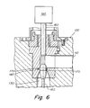
- FIG. 6 is a closeup view of the bulbous protrusion portion of the valve pin show in the FIG. 5 apparatus showing the bulbous protrusion in a fluid flow stop position;
- FIG. 7 is a schematic, side cross-sectional view of a portion of an injection molding apparatus showing a heater apparatus arranged/fitted around the downstream nozzle end of a fluid flow channel, where the nozzle has a controllably movable valve pin having a wedge shaped protrusion that restricts flow upon downstream movement of the pin.
- FIG. 1 shows a heater apparatus 10 according to the invention.
- the heater apparatus 10 comprises an inner tube 20 and an outer tube 30 , both of the tubes typically being comprised of materials having the same or substantially the same coefficients of thermal expansion.
- the inner tube 20 is typically comprised of a material having a relatively high coefficient of thermal expansion such as copper, aluminum, and alloys therewith.
- the outer tube 30 is typically comprised of a heat reflective material such as stainless steel and alloys therewith.
- the materials comprising both tubes 20 , 30 are preferably resistant to oxidation and corrosion.
- the inner 20 and outer 30 tubes are mounted at opposing terminal ends by rings 50 , 60 in spaced relationship whereby an enclosed space 70 is formed between the inner surface 32 of the outer tube and the outer surface 22 of the inner tube 20 .
- the heater coils 40 are enclosed within the space 70 and are preferably mounted in contact engagement with the outer surface 22 of the inner tube 20 so as to most efficiently transmit heat energy to the body of the heat conductive material of which tube 20 is comprised.
- Heater coils 40 are connected by conventional electrical wiring 102 to a source of heat generating energy 100 such as an electrical voltage or current generator which can be readily controlled to transmit electrical energy to coils 40 and raise the temperature of the coils 40 to one or more preselected temperatures.
- a source of heat generating energy 100 such as an electrical voltage or current generator which can be readily controlled to transmit electrical energy to coils 40 and raise the temperature of the coils 40 to one or more preselected temperatures.
- Other sources of heat generation may alternatively be employed such as a fluid material which is controllably heated at a source location 100 and routed through tubes 40 .
- the heater mechanism may alternatively be constructed in other formats such as heatable sheets or strips akin to coils 40 which wrap around the outer surface 22 of the inner tube 20 .
- the inner surface 24 of inner tube 20 is fitted around the outer surface 82 of a nozzle body 80 that is mounted at an upstream end to sealably communicate with a fluid flow channel 110 of a heated fluid distribution manifold or hotrunner 120 .
- the diameter A of inner tube 20 is typically configured to be essentially the same as or only very slightly larger at room temperature than the outer surface diameter of the nozzle body 80 such that nozzle body 80 is snugly received within the hollow interior of heater tube 20 .
- the manifold 110 of the injection molding apparatus 125 is heated to an elevated temperature to maintain the fluid injected into the channel 120 in a readily fluid flow state.
- the heater assembly in the arrangement shown in FIGS.
- the inner heater tube 20 is comprised of a material, typically highly heat conductive metal such as steel, stainless steel, aluminum or other suitable metal material, that expands radially 140 , FIGS. 2, 3 upon heating to elevated temperature.
- the rings 50 , 60 also expand radially 142 , FIGS. 1, 3 upon heating to an elevated temperature.
- the rings 50 , 60 are comprised of a relatively low thermally expansive metal material, such as titanium, steel, stainless steel or other suitable metal, which has a coefficient of thermal expansion which is less than the coefficient of thermal expansion of the metal material of which the inner tube 20 is comprised.
- the rings 50 , 60 thus restrain the higher radially expanding 140 inner tube by virtue of an inner circumferential surface 58 , FIGS. 3, 3 a of the rings being frictionally engaged around and against an opposing outer circumferential surface 28 , FIGS. 2, 3 of the inner tube 20 .
- the outer circumferential mounting surface 28 of inner tube 20 has a diameter D which is essentially the same or only very slightly smaller at room temperature than the inner circumferential diameter D, FIG. 3 a , of the mating surface 28 , FIGS. 3, 3 a of the rings 50 , 60 .
- the tube radially expands 140 to a greater degree than the rings 50 , 60 radially expand 142 and thus the pressure between surfaces 58 and 28 increases as the apparatus is heated creating a radially inward force 144 by surface 58 against surface 28 .
- the increased radially inward pressure force 144 created by rings 50 , 60 against surface 28 of the inner tube 20 causes increased pressure of the inner circumferential surface 24 of tube 20 against the outer surface 82 , FIGS. 5, 7 of the nozzle body 80 thus increasing the heat conductive contact area and heat conductive efficiency between inner tube 20 and nozzle body 80 .
- the rings 50 , 60 thus act to clamp the inner tube 20 against the outer surface of the nozzle 80 upon heating of the apparatus 10 , 125 to operating temperatures.
- the inner tube 20 is typically provided with a slot 25 , FIG. 25, through the entire body width of tube 20 which allows the tube body 20 to more easily contract in circumference under the inward pressure force 144 being exerted on the outer circumferential surface of the tube 20 by rings 50 , 60 .
- the slot 25 is parallel to the axis C of the tube 30 , FIGS. 1, 2 .
- the slot 25 may alternatively be slanted at an angle relative to axis C or curved, curvilinear, zig-zag or arranged in some other pattern relative to axis C other than the straight, parallel arrangement shown in FIG. 2 .
- the rings are mounted at the terminal opposing ends of the inner tube 20 .
- the longitudinal length X, FIG. 3 a of the inner circumferential engagement surfaces 58 of the rings 50 , 60 are very short or foreshortened relative to the overall longitudinal length L, FIG. 1, of the inner 20 and outer 30 tubes.
- the longitudinal engagement length X, FIG. 3 a is less than about 10% of the total longitudinal length L of tube 20 , and preferably less than about 5% and most preferably less than about 3%.
- the inner engagement surface 58 of the rings 50 , 60 may include screw teeth which are complementary with screw teeth provided on the outer mounting surface 28 of the heater tube 20 such that the rings 50 , 60 may simply be screwed onto the top and bottom terminal ends of the tube 20 .
- one screwably engageable ring 50 or 60 may be first screwed on to an end of the tube 20 , then the outer ring 30 may be slid over the outside of tube 20 and one end of the outer tube 30 positioned against the abutment, mounting surfaces 56 , 57 , FIG. 3 a , to assume the position of tube 30 shown in FIGS. 1, 3 .
- the other of the rings may then be screwed onto the other end of the tube 20 and the other end of tube 30 positioned snugly against mounting surfaces 56 , 57 of the other of rings 50 , 60 such that tube 30 is stationarily held in the position shown in FIGS. 1, 3 relative to inner tube 20 .
- the inner enclosed space 70 is created by the assembly and mounting of the larger inner diameter outer tube 30 around the smaller outer diameter tube 20 .
- the mounting and clamping rings 50 , 60 enclose the air space 70 off from the outside environment which creates a somewhat insulated air space that becomes elevated in temperature and insulated from cooling influences that may be conducted to the heated metal structures 120 , 80 which are in conductive contact with the mold body 127 which is being substantially cooled relative to the nozzle 80 and manifold 120 during an injection cycle.
- the inner enclosed space 70 is maintained as heat retentive reservoir, in part by the outer tube 30 which reflects and retains heat within the space 70 , by virtue of its inner surface 32 being spaced a certain radial distance away from both the heater coil elements 40 and the outer surface 22 of the inner tube 20 .
- the outer tube 30 is typically comprised of a heat reflective metal material such as steel or stainless steel.
- the rings 50 , 60 are shown as being mountable/screwable onto the two opposing terminal ends of the tube 20 .
- the rings 50 , 60 may be mounted, attached, screwed or otherwise connected to the outer surface of tube 20 at any position along the longitudinal length of tube 20 .
- the tubes 20 , 30 and the rings 50 , 60 are shown in the Figures in cylindrical format/design/configuration.
- the tubes and rings may have a variety of shapes in radial section such as square, oval, hexagonal, pentagonal or any other tubular shape that matches or is complementary to the outer circumference of the fluid flow channel structure that the heater assembly is intended to be mounted around.
- the heater assembly is mounted around the more downstream end of the fluid flow channel, i.e. around the nozzle 80 , which is immediately upstream of the gate of the mold 127 , FIG. 5, into which the fluid is injected and eventually cooled during an injection cycle into a molded part.
- the heater assembly 10 may alternatively be mounted around any portion of any fluid flow channel in the system, e.g. around the hotrunner channel 110 or another fluid flow channel section that is configured to allow a tubular heater construction to be mounted around.
- a heater assembly may, for example, be mounted around the barrel (not shown) of an injection molding machine itself or around other nozzles that feed into other distribution channels or molds in a manifold or runner in the system.
- FIGS. 5-7 show exemplary embodiments of heater assemblies used in controllable fluid flow rate injection systems.
- the heater assembly is engaged around a nozzle 80 having a valve pin 160 having a bulbous section 170 which controls the rate of fluid flow through the bore 130 of the nozzle by upstream movement 173 of the outside curvilinear surface of bulb 170 into the throat 180 of a restriction area in the flow channel 110 , 130 leading to gate 126 .
- the spacing 190 between the outside curvilinear surface of bulb 170 can be varied, and thus the flow rate varied, depending on the positioning of the bulb 170 relative to the inside surface of the channel 130 in the area of the throat 180 . As shown in FIG.
- the bulb 170 has a maximum diameter section 172 which upon full upstream withdrawal of pin 160 by controllable actuator 190 to the position shown in FIG. 6, the bulb maximum diameter section 172 engages the inside surface of the throat 180 section and fluid flow from channel 110 to bore/channel 130 is stopped.
- the heater assembly 10 assists in the course of an injection cycle being controlled by operation of actuator 190 which may be controlled by an algorithm utilizing a value corresponding to a sensed condition of the fluid flow provided by a sensor signal sent by a sensor such as sensor 150 .
- the heater assembly 10 assists in the injection cycle/process by maintaining the temperature at a desired level in a channel section 130 that is occasionally shut off from channel section 110 . At such shut off periods, the fluid temperature in channel 110 may differ from the temperature in channel 130 , and the temperature of nozzle body 80 may begin to cool relative to manifold 120 .
- the pin 160 has a flow controlling protrusion 210 having an upper conically shaped surface 260 and a lower conically shaped surface 220 and a maximum diameter section 230 . Fluid flow is controlled, restricted and eventually stopped by downstream movement 177 of pin 160 . Depending on the precise position of the outside surface of lower conical surface 220 of the pin protrusion 210 relative to the complementary conical receiving/mating surface 240 of the channel/bore 130 , the size of the spacing 250 will be more or less and, in turn, the fluid flow from channel 110 to channel 130 will be more or less. When pin 160 moved fully forward/downstream to the point where surface 220 engages surface 240 , fluid flow will be completely stopped. As in the FIG.
- axial movement of the pin 160 may be controlled by an algorithm using a variable based on a signal received from the sensor 150 which senses a condition of the fluid flowing in a channel 11 , 130 or the like.
- Fluid conditions typically sensed are fluid pressure, temperature, flow rate, viscosity and the like.
Abstract
Description
Claims (21)
Priority Applications (1)
| Application Number | Priority Date | Filing Date | Title |
|---|---|---|---|
| US10/200,488 US6683283B2 (en) | 2002-05-10 | 2002-07-23 | Apparatus and method for heating injection molding fluid |
Applications Claiming Priority (2)
| Application Number | Priority Date | Filing Date | Title |
|---|---|---|---|
| US37894502P | 2002-05-10 | 2002-05-10 | |
| US10/200,488 US6683283B2 (en) | 2002-05-10 | 2002-07-23 | Apparatus and method for heating injection molding fluid |
Publications (2)
| Publication Number | Publication Date |
|---|---|
| US20030209532A1 US20030209532A1 (en) | 2003-11-13 |
| US6683283B2 true US6683283B2 (en) | 2004-01-27 |
Family
ID=29406386
Family Applications (1)
| Application Number | Title | Priority Date | Filing Date |
|---|---|---|---|
| US10/200,488 Expired - Lifetime US6683283B2 (en) | 2002-05-10 | 2002-07-23 | Apparatus and method for heating injection molding fluid |
Country Status (1)
| Country | Link |
|---|---|
| US (1) | US6683283B2 (en) |
Cited By (19)
| Publication number | Priority date | Publication date | Assignee | Title |
|---|---|---|---|---|
| US20030173411A1 (en) * | 2002-03-18 | 2003-09-18 | Fujitsu Limited | Method of heating superposed components and heating apparatus therefor |
| US20040051195A1 (en) * | 2002-09-18 | 2004-03-18 | Isao Okamura | Metering device for a nozzle of an injection molding apparatus |
| US20040057709A1 (en) * | 2002-09-19 | 2004-03-25 | John Leary | Aircraft water heating system |
| US20040109916A1 (en) * | 2002-12-03 | 2004-06-10 | Mold-Masters Limited | Hot runner co-injection nozzle |
| US20040161490A1 (en) * | 2003-02-13 | 2004-08-19 | Denis Babin | Valve gated injection molding system with independent flow control |
| US20040166189A1 (en) * | 2003-02-25 | 2004-08-26 | Mold-Masters Limited | Injection molding system with flow control |
| US7147458B2 (en) | 2002-10-25 | 2006-12-12 | Mold Hotrunner Solutions, Inc. | Apparatus for heating injection molding fluid |
| US20060292256A1 (en) * | 2000-03-08 | 2006-12-28 | Gellert Jobst U | Hot runner nozzle with removable sleeve |
| US20070119287A1 (en) * | 2005-11-28 | 2007-05-31 | Airchime Manufacturing Co. Ltd. | Heated air horn |
| US20070292557A1 (en) * | 2006-06-16 | 2007-12-20 | Mold-Masters Limited | Open Loop Pressure Control For Injection Molding |
| US20080085334A1 (en) * | 2006-10-10 | 2008-04-10 | Husky Injection Molding Systems Ltd. | Hot Runner System Sensor |
| US20080152751A1 (en) * | 2006-12-21 | 2008-06-26 | Mold-Masters (2007) Limited | Valve for Co-Injection Molding Apparatus |
| US20090029307A1 (en) * | 2006-03-23 | 2009-01-29 | Takashi Ohara | Heat-treating furnace |
| US20090032519A1 (en) * | 2007-08-03 | 2009-02-05 | Schlipf Andreas | Electric cartridge type heater |
| DE202010002136U1 (en) | 2010-02-09 | 2010-05-20 | Türk & Hillinger GmbH | Electric heater |
| CN101835297A (en) * | 2010-04-29 | 2010-09-15 | 杨启新 | Energy-saving device of plastic machine |
| US20110299838A1 (en) * | 2009-12-29 | 2011-12-08 | Synventive Molding Solutions, Inc. | Heating apparatus for fluid flow channel |
| US8834150B2 (en) | 2012-10-09 | 2014-09-16 | Mold Hotrunner Solutions Inc. | Valve gate cylinder and housing with microgap seal |
| US10921025B2 (en) | 2015-07-22 | 2021-02-16 | National Machine Group | Hot water tank |
Families Citing this family (3)
| Publication number | Priority date | Publication date | Assignee | Title |
|---|---|---|---|---|
| CN102791050A (en) * | 2012-08-01 | 2012-11-21 | 福州市台江区振斌高效电磁聚能科技研究所 | Heater of plastic extruding machine |
| CN104640247A (en) * | 2015-02-04 | 2015-05-20 | 邹中宝 | Electro-thermal generator |
| DE112016006531A5 (en) * | 2016-03-01 | 2018-12-06 | Ferrofacta Gmbh | Diecast nozzle system |
Citations (67)
| Publication number | Priority date | Publication date | Assignee | Title |
|---|---|---|---|---|
| US3535742A (en) | 1967-07-31 | 1970-10-27 | Paul Marcus | Molding apparatus valve and nozzle |
| DE2034163A1 (en) | 1969-07-11 | 1971-02-11 | Matsuda Shoji Urawa Saitama, Mitsubishi Petrochemical Co Ltd Tokio (Japan) | Injection molding machine |
| US3780764A (en) | 1972-04-07 | 1973-12-25 | Union Carbide Corp | Nozzle shut-off and flow control valve |
| US3820928A (en) | 1964-12-29 | 1974-06-28 | J Lemelson | Control system for molding |
| US3861841A (en) | 1971-06-14 | 1975-01-21 | Robert Hanning | Machine for the injection molding of a mixture of plasticized synthetic material |
| DE2401168A1 (en) | 1974-01-10 | 1975-07-31 | Control Process Inc | Injection pressure control - by sensing mould pressure and heater or obstructing material flow accordingly |
| US3952927A (en) | 1974-04-26 | 1976-04-27 | Standard Oil Company | Injection nozzle having guides for nozzle rod |
| US4389002A (en) | 1980-02-07 | 1983-06-21 | Kona Corporation | Injection molding nozzle |
| JPS58142833A (en) | 1982-02-19 | 1983-08-25 | Kobe Steel Ltd | Control method for injection molding machine |
| US4500279A (en) | 1983-07-06 | 1985-02-19 | Kona Corporation | Heat pipe manifold system |
| US4521179A (en) | 1983-02-24 | 1985-06-04 | Gellert Jobst U | Injection molding core ring gate system |
| JPS60212321A (en) | 1984-04-06 | 1985-10-24 | Yazaki Kako Kk | Quantity control of resin for injection compression molding |
| JPS6163428A (en) | 1984-09-04 | 1986-04-01 | Nippon Denso Co Ltd | Mold assembly |
| US4588367A (en) | 1984-07-16 | 1986-05-13 | Husky Injection Molding Systems Ltd. | Hot runner manifold for injection molding machine |
| US4592711A (en) | 1983-03-10 | 1986-06-03 | Gilbert Capy | Apparatus for fabricating plastic parts |
| US4701292A (en) | 1984-09-13 | 1987-10-20 | Husky Injection Molding Systems Ltd. | Method for pressure molding objects of different resins |
| US4747770A (en) | 1986-10-17 | 1988-05-31 | Mold-Masters Limited | Fluid cooled hydraulic actuating mechanism for injection molding |
| US4755131A (en) | 1986-10-31 | 1988-07-05 | Mold-Masters Limited | Fluid cooled hydraulic actuating mechanism for single cavity injection molding |
| US4768945A (en) | 1987-10-16 | 1988-09-06 | Mold-Masters Limited | Injection molding nozzle having grounded heating element brazed into pointed tip |
| US4793795A (en) | 1987-10-16 | 1988-12-27 | Mold-Masters Limited | Injection molding system having clamped rotatable nozzles and method |
| US4863369A (en) | 1986-05-12 | 1989-09-05 | Husky Injection Molding Systems Ltd. | Injection molding with shooting pots |
| US4931234A (en) | 1986-05-12 | 1990-06-05 | Husky Injection Molding Systems Ltd. | Coinjection of hollow articles and preforms |
| US4932854A (en) | 1987-04-07 | 1990-06-12 | Kabushiki Kaisha Komatsu Seisakusho | Apparatus for control of injection molding machine |
| US5007821A (en) | 1990-02-23 | 1991-04-16 | Mold-Masters Limited | Injection molding manifold having a pair of cooling bores on opposite sides of the melt passage |
| US5009718A (en) | 1988-11-21 | 1991-04-23 | Mold-Masters Limited | Thermocouple construction |
| US5078589A (en) | 1990-06-15 | 1992-01-07 | Osuna Diaz J M | Multicavity injection molding apparatus having precision adjustment and shut off of injection flow to individual mold cavities |
| US5141696A (en) | 1986-06-30 | 1992-08-25 | Osuna Diaz J M | Method for injection molding using flow adjusting arrangement |
| US5149547A (en) | 1991-06-12 | 1992-09-22 | Automotive Plastic Technologies, Inc. | Apparatus for multi-cavity injection molding |
| US5192555A (en) | 1990-02-16 | 1993-03-09 | Husky Injection Molding Systems Ltd. | Apparatus for molding plastic articles |
| US5225662A (en) | 1992-01-13 | 1993-07-06 | Husky Injection Molding Systems, Ltd. | Flexible heating element for a hot runner housing including method of manufacture and method of installation |
| US5281374A (en) | 1987-05-29 | 1994-01-25 | Kabushiki Kaisha Komatsu Seisakusho | Automatic purging method for injection molding machine |
| US5288222A (en) | 1989-10-16 | 1994-02-22 | Marianne Wieser | Mould for injection moulding machines |
| US5356576A (en) | 1991-03-26 | 1994-10-18 | Mannesmann Aktiengesellschaft | Process for the manufacture of plastic moldings with decorative coating |
| US5360333A (en) | 1992-09-30 | 1994-11-01 | Husky Injection Molding Systems Ltd. | Band heater clamp arrangement for an injection molding machine |
| US5378139A (en) | 1993-09-07 | 1995-01-03 | Husky Injection Molding Systems Ltd. | Hook nozzle for inside gated mold |
| US5389315A (en) | 1992-11-04 | 1995-02-14 | Kasai Kogyo Co., Ltd. | Method and device for mold press forming |
| US5492467A (en) | 1993-12-30 | 1996-02-20 | Kona Corporation | Apparatus for injection molding articles of amorphous polyethylene terephthalate |
| US5545028A (en) | 1994-08-16 | 1996-08-13 | Kona Corporation | Bushing tip for injection molding apparatus |
| US5554395A (en) | 1993-08-12 | 1996-09-10 | Kona Corporation | Open bore injection molding apparatus |
| US5556582A (en) | 1995-02-17 | 1996-09-17 | Stanford University | Injection molding gate flow control |
| US5591366A (en) | 1994-06-23 | 1997-01-07 | Husky Injection Molding Systems Ltd. | Injection molding heater including circuit breaking means |
| US5601773A (en) | 1995-05-12 | 1997-02-11 | Cincinnati Milacron Inc. | Co-injection machine |
| WO1997043105A1 (en) | 1996-05-13 | 1997-11-20 | Flexiject Innovation Hb | Method and system for injection moulding of thermoplasts and thermoelastomers |
| WO1998056564A1 (en) | 1997-06-13 | 1998-12-17 | Incoe Corporation | Injection molding system with sequential gate control |
| US5871786A (en) | 1997-04-04 | 1999-02-16 | Kona Corporation | Tip heated hot runner nozzle |
| CA2246771A1 (en) | 1997-09-02 | 1999-03-02 | Kona Corporation | Hot runner system for coinjection molding |
| US5885624A (en) | 1996-06-17 | 1999-03-23 | Toshiba Machine, Co., Ltd. | Apparatus for controlling injection molding machines |
| US5885628A (en) | 1993-08-12 | 1999-03-23 | Dynisco, Inc. | Injection molding nozzle |
| US5894025A (en) | 1997-06-13 | 1999-04-13 | Kona Corporation | Valve pin actuator |
| EP0911137A2 (en) | 1997-10-20 | 1999-04-28 | Husky Injection Molding Systems Ltd. | Multiple gating nozzle |
| US5916605A (en) | 1996-09-27 | 1999-06-29 | Dynisco Hotrunners, Inc. | Valve actuated injection molding apparatus |
| DE29909535U1 (en) | 1998-06-02 | 1999-08-12 | Engel Gmbh Maschbau | Injection molding device for the production of a variety of plastic parts |
| US5948448A (en) | 1997-11-18 | 1999-09-07 | Eurotool, Inc. | Apparatus for controlling plastic melt flow in injection molding machines |
| DE19811466A1 (en) | 1998-03-17 | 1999-09-23 | Zahoransky Formenbau Gmbh | Die-casting tool with a die having several cavities |
| WO1999054109A1 (en) | 1998-04-21 | 1999-10-28 | Dynisco Hotrunners, Inc. | Manifold system having flow control |
| WO1999059795A1 (en) | 1998-05-15 | 1999-11-25 | Otto Hofstetter Ag Werkzeug- Und Formenbau | Injection moulding tool |
| US6000831A (en) | 1997-02-12 | 1999-12-14 | American Msi Corporation | Injection mold data transmission system |
| US6027328A (en) | 1996-02-26 | 2000-02-22 | Herbst; Richard | Apparatus for injection-molding plastic material items |
| US6043466A (en) * | 1998-02-20 | 2000-03-28 | Husky Injection Molding Systems Ltd. | Hot runner heating clamp |
| EP1052078A1 (en) | 1999-05-08 | 2000-11-15 | HEKUMA Herbst Maschinenbau GmbH | Individual process control in a mould |
| WO2001008462A2 (en) | 1998-05-20 | 2001-02-08 | Dynisco Hotrunners, Inc., Canada | System for individual control of multiple valve gates |
| US6261084B1 (en) | 1998-08-28 | 2001-07-17 | Synventive Moldings Solutions Canada, Inc. | Elastically deformable nozzle for injection molding |
| US6287107B1 (en) | 1997-09-02 | 2001-09-11 | Synventive Molding Solutions, Inc. | Apparatus for proportionally controlling fluid delivery to a mold |
| US6294122B1 (en) | 1998-06-26 | 2001-09-25 | Synventive Molding Solutions, Inc. | Electric actuator for a melt flow control pin |
| EP1142686A1 (en) | 1999-11-19 | 2001-10-10 | Dynisco Hotrunners, Inc. | Apparatus and method for proportionally controlling fluid delivery to readily replaceable mold inserts |
| US6309208B1 (en) | 1997-06-13 | 2001-10-30 | Synventive Molding Solutions, Inc. | Apparatus for proportionally controlling fluid delivery to a mold |
| WO2002036324A1 (en) | 2000-10-30 | 2002-05-10 | Synventive Molding Solutions, Inc. | Controlled injection using manifold having multiple feed channels |
-
2002
- 2002-07-23 US US10/200,488 patent/US6683283B2/en not_active Expired - Lifetime
Patent Citations (80)
| Publication number | Priority date | Publication date | Assignee | Title |
|---|---|---|---|---|
| US3820928A (en) | 1964-12-29 | 1974-06-28 | J Lemelson | Control system for molding |
| US3820928B1 (en) | 1964-12-29 | 1994-02-22 | H. Lemelson Jerome | |
| US3535742A (en) | 1967-07-31 | 1970-10-27 | Paul Marcus | Molding apparatus valve and nozzle |
| DE2034163A1 (en) | 1969-07-11 | 1971-02-11 | Matsuda Shoji Urawa Saitama, Mitsubishi Petrochemical Co Ltd Tokio (Japan) | Injection molding machine |
| US3861841A (en) | 1971-06-14 | 1975-01-21 | Robert Hanning | Machine for the injection molding of a mixture of plasticized synthetic material |
| US3780764A (en) | 1972-04-07 | 1973-12-25 | Union Carbide Corp | Nozzle shut-off and flow control valve |
| DE2401168A1 (en) | 1974-01-10 | 1975-07-31 | Control Process Inc | Injection pressure control - by sensing mould pressure and heater or obstructing material flow accordingly |
| US3952927A (en) | 1974-04-26 | 1976-04-27 | Standard Oil Company | Injection nozzle having guides for nozzle rod |
| US4389002A (en) | 1980-02-07 | 1983-06-21 | Kona Corporation | Injection molding nozzle |
| JPS58142833A (en) | 1982-02-19 | 1983-08-25 | Kobe Steel Ltd | Control method for injection molding machine |
| US4521179A (en) | 1983-02-24 | 1985-06-04 | Gellert Jobst U | Injection molding core ring gate system |
| US4592711A (en) | 1983-03-10 | 1986-06-03 | Gilbert Capy | Apparatus for fabricating plastic parts |
| US4500279A (en) | 1983-07-06 | 1985-02-19 | Kona Corporation | Heat pipe manifold system |
| CA1204906A (en) | 1983-07-06 | 1986-05-27 | Paul M. Swenson | Heat pipe manifold system |
| JPS60212321A (en) | 1984-04-06 | 1985-10-24 | Yazaki Kako Kk | Quantity control of resin for injection compression molding |
| US4588367A (en) | 1984-07-16 | 1986-05-13 | Husky Injection Molding Systems Ltd. | Hot runner manifold for injection molding machine |
| JPS6163428A (en) | 1984-09-04 | 1986-04-01 | Nippon Denso Co Ltd | Mold assembly |
| US4701292A (en) | 1984-09-13 | 1987-10-20 | Husky Injection Molding Systems Ltd. | Method for pressure molding objects of different resins |
| US4863369A (en) | 1986-05-12 | 1989-09-05 | Husky Injection Molding Systems Ltd. | Injection molding with shooting pots |
| US4931234A (en) | 1986-05-12 | 1990-06-05 | Husky Injection Molding Systems Ltd. | Coinjection of hollow articles and preforms |
| US5141696A (en) | 1986-06-30 | 1992-08-25 | Osuna Diaz J M | Method for injection molding using flow adjusting arrangement |
| US4747770A (en) | 1986-10-17 | 1988-05-31 | Mold-Masters Limited | Fluid cooled hydraulic actuating mechanism for injection molding |
| US4755131A (en) | 1986-10-31 | 1988-07-05 | Mold-Masters Limited | Fluid cooled hydraulic actuating mechanism for single cavity injection molding |
| US4932854A (en) | 1987-04-07 | 1990-06-12 | Kabushiki Kaisha Komatsu Seisakusho | Apparatus for control of injection molding machine |
| US5281374A (en) | 1987-05-29 | 1994-01-25 | Kabushiki Kaisha Komatsu Seisakusho | Automatic purging method for injection molding machine |
| US4768945A (en) | 1987-10-16 | 1988-09-06 | Mold-Masters Limited | Injection molding nozzle having grounded heating element brazed into pointed tip |
| US4793795A (en) | 1987-10-16 | 1988-12-27 | Mold-Masters Limited | Injection molding system having clamped rotatable nozzles and method |
| US5009718A (en) | 1988-11-21 | 1991-04-23 | Mold-Masters Limited | Thermocouple construction |
| US5288222A (en) | 1989-10-16 | 1994-02-22 | Marianne Wieser | Mould for injection moulding machines |
| US5192555A (en) | 1990-02-16 | 1993-03-09 | Husky Injection Molding Systems Ltd. | Apparatus for molding plastic articles |
| US5007821A (en) | 1990-02-23 | 1991-04-16 | Mold-Masters Limited | Injection molding manifold having a pair of cooling bores on opposite sides of the melt passage |
| US5078589A (en) | 1990-06-15 | 1992-01-07 | Osuna Diaz J M | Multicavity injection molding apparatus having precision adjustment and shut off of injection flow to individual mold cavities |
| US5356576A (en) | 1991-03-26 | 1994-10-18 | Mannesmann Aktiengesellschaft | Process for the manufacture of plastic moldings with decorative coating |
| US5149547A (en) | 1991-06-12 | 1992-09-22 | Automotive Plastic Technologies, Inc. | Apparatus for multi-cavity injection molding |
| US5225662A (en) | 1992-01-13 | 1993-07-06 | Husky Injection Molding Systems, Ltd. | Flexible heating element for a hot runner housing including method of manufacture and method of installation |
| US5360333A (en) | 1992-09-30 | 1994-11-01 | Husky Injection Molding Systems Ltd. | Band heater clamp arrangement for an injection molding machine |
| US5389315A (en) | 1992-11-04 | 1995-02-14 | Kasai Kogyo Co., Ltd. | Method and device for mold press forming |
| US5554395A (en) | 1993-08-12 | 1996-09-10 | Kona Corporation | Open bore injection molding apparatus |
| US5885628A (en) | 1993-08-12 | 1999-03-23 | Dynisco, Inc. | Injection molding nozzle |
| US5980237A (en) | 1993-08-12 | 1999-11-09 | Dynisco, Inc. | Injection molding nozzle |
| US5378139A (en) | 1993-09-07 | 1995-01-03 | Husky Injection Molding Systems Ltd. | Hook nozzle for inside gated mold |
| US5674439A (en) | 1993-12-30 | 1997-10-07 | Kona Corporation | System and apparatus for injection molding articles of amorphous polyethylene terephthalate and similar materials |
| US5492467A (en) | 1993-12-30 | 1996-02-20 | Kona Corporation | Apparatus for injection molding articles of amorphous polyethylene terephthalate |
| US5591366A (en) | 1994-06-23 | 1997-01-07 | Husky Injection Molding Systems Ltd. | Injection molding heater including circuit breaking means |
| US5545028A (en) | 1994-08-16 | 1996-08-13 | Kona Corporation | Bushing tip for injection molding apparatus |
| US5556582A (en) | 1995-02-17 | 1996-09-17 | Stanford University | Injection molding gate flow control |
| US5601773A (en) | 1995-05-12 | 1997-02-11 | Cincinnati Milacron Inc. | Co-injection machine |
| US6027328A (en) | 1996-02-26 | 2000-02-22 | Herbst; Richard | Apparatus for injection-molding plastic material items |
| WO1997043105A1 (en) | 1996-05-13 | 1997-11-20 | Flexiject Innovation Hb | Method and system for injection moulding of thermoplasts and thermoelastomers |
| US5885624A (en) | 1996-06-17 | 1999-03-23 | Toshiba Machine, Co., Ltd. | Apparatus for controlling injection molding machines |
| US5916605A (en) | 1996-09-27 | 1999-06-29 | Dynisco Hotrunners, Inc. | Valve actuated injection molding apparatus |
| US5948450A (en) | 1996-09-27 | 1999-09-07 | Dynisco Hotrunners, Inc. | Valve actuated injection molding apparatus |
| US6000831A (en) | 1997-02-12 | 1999-12-14 | American Msi Corporation | Injection mold data transmission system |
| US5871786A (en) | 1997-04-04 | 1999-02-16 | Kona Corporation | Tip heated hot runner nozzle |
| US6309208B1 (en) | 1997-06-13 | 2001-10-30 | Synventive Molding Solutions, Inc. | Apparatus for proportionally controlling fluid delivery to a mold |
| US5894025A (en) | 1997-06-13 | 1999-04-13 | Kona Corporation | Valve pin actuator |
| WO1998056564A1 (en) | 1997-06-13 | 1998-12-17 | Incoe Corporation | Injection molding system with sequential gate control |
| US6419870B1 (en) | 1997-06-13 | 2002-07-16 | Synventive Molding Solutions, Inc. | Valve pin actuator |
| US6062840A (en) | 1997-09-02 | 2000-05-16 | Dynisco Hotrunners, Inc. | Hot runner system for coinjection molding |
| US6287107B1 (en) | 1997-09-02 | 2001-09-11 | Synventive Molding Solutions, Inc. | Apparatus for proportionally controlling fluid delivery to a mold |
| CA2246771A1 (en) | 1997-09-02 | 1999-03-02 | Kona Corporation | Hot runner system for coinjection molding |
| US6261075B1 (en) | 1997-09-02 | 2001-07-17 | Synventive Molding Solutions, Inc. | Hot runner system for coinjection molding |
| EP0911137A2 (en) | 1997-10-20 | 1999-04-28 | Husky Injection Molding Systems Ltd. | Multiple gating nozzle |
| US5948448A (en) | 1997-11-18 | 1999-09-07 | Eurotool, Inc. | Apparatus for controlling plastic melt flow in injection molding machines |
| US6043466A (en) * | 1998-02-20 | 2000-03-28 | Husky Injection Molding Systems Ltd. | Hot runner heating clamp |
| DE19811466A1 (en) | 1998-03-17 | 1999-09-23 | Zahoransky Formenbau Gmbh | Die-casting tool with a die having several cavities |
| US6436320B1 (en) | 1998-04-21 | 2002-08-20 | Synventive Molding Solutions, Inc. | Method using manifold system having flow control |
| US6254377B1 (en) | 1998-04-21 | 2001-07-03 | Synventive Molding Solutions, Inc. | Manifold system having flow control using extended valve pin |
| US6343921B1 (en) | 1998-04-21 | 2002-02-05 | Synventive Molding Solutions | Manifold system having flow control using separate cavities |
| WO1999054109A1 (en) | 1998-04-21 | 1999-10-28 | Dynisco Hotrunners, Inc. | Manifold system having flow control |
| US6361300B1 (en) | 1998-04-21 | 2002-03-26 | Synventive Molding Solutions, Inc. | Manifold system having flow control |
| US6343922B1 (en) | 1998-04-21 | 2002-02-05 | Synventive Molding Solutions | Manifold system having flow control using pressure transducers |
| WO1999059795A1 (en) | 1998-05-15 | 1999-11-25 | Otto Hofstetter Ag Werkzeug- Und Formenbau | Injection moulding tool |
| WO2001008462A2 (en) | 1998-05-20 | 2001-02-08 | Dynisco Hotrunners, Inc., Canada | System for individual control of multiple valve gates |
| DE29909535U1 (en) | 1998-06-02 | 1999-08-12 | Engel Gmbh Maschbau | Injection molding device for the production of a variety of plastic parts |
| US6294122B1 (en) | 1998-06-26 | 2001-09-25 | Synventive Molding Solutions, Inc. | Electric actuator for a melt flow control pin |
| US6261084B1 (en) | 1998-08-28 | 2001-07-17 | Synventive Moldings Solutions Canada, Inc. | Elastically deformable nozzle for injection molding |
| EP1052078A1 (en) | 1999-05-08 | 2000-11-15 | HEKUMA Herbst Maschinenbau GmbH | Individual process control in a mould |
| EP1142686A1 (en) | 1999-11-19 | 2001-10-10 | Dynisco Hotrunners, Inc. | Apparatus and method for proportionally controlling fluid delivery to readily replaceable mold inserts |
| WO2002036324A1 (en) | 2000-10-30 | 2002-05-10 | Synventive Molding Solutions, Inc. | Controlled injection using manifold having multiple feed channels |
Non-Patent Citations (18)
| Title |
|---|
| Abstract-Japanese Publication No. 20 00141439, May 23, 2000, Kobe Steel Ltd., "Injection Compression Molding Device." |
| Abstract—Japanese Publication No. 20 00141439, May 23, 2000, Kobe Steel Ltd., "Injection Compression Molding Device." |
| Abstract-Japanese Publication No. 58 142833, Aug. 25, 1983, Kobe Steel Ltd., "Control Method for Injection Molding Machine". |
| Abstract—Japanese Publication No. 58 142833, Aug. 25, 1983, Kobe Steel Ltd., "Control Method for Injection Molding Machine". |
| Abstract-Japanese Publication No. 60 212321, Oct. 24, 1985, Yazaki Kako KK, "Quantity Control of Resin for Injection Compression Molding". |
| Abstract—Japanese Publication No. 60 212321, Oct. 24, 1985, Yazaki Kako KK, "Quantity Control of Resin for Injection Compression Molding". |
| Abstract-Japanese Publication No. 61 063428, Jan. 4, 1986, Nippon Densco Co. Ltd., "Mold Assembly". |
| Abstract—Japanese Publication No. 61 063428, Jan. 4, 1986, Nippon Densco Co. Ltd., "Mold Assembly". |
| Abstract-Japanese Publication No. 63 166511, Jul. 9, 1988, Nissei Plastics Ind. Co., "Injection Molding." |
| Abstract—Japanese Publication No. 63 166511, Jul. 9, 1988, Nissei Plastics Ind. Co., "Injection Molding." |
| European Search Report, dated Feb. 28, 2001, EP Application No. 00 12 4358. |
| International Search Report, dated Jun. 5, 2002, PCT/US02/08364. |
| International Search Report, dated Mar. 8, 2002, PCT/US01/42795. |
| International Search Report, mailed Feb. 2, 1999, PCT/US98/10798. |
| International Search Report, mailed Jun. 22, 2001, PCT/US01/04674. |
| Kazmer, David O., "Dynamic Feed Control: A New Method for Injection Molding of High Quality Plastic Parts," A Dissertation submitted to the Design Division of Mechanical Engineering and the Committee on Graduate Studies in Partial Fulfillment of the Requirements for the Degree of Doctor of Philosophy in Mechanical Engineering, Jun. 1995, (ii-xix, 2-199). |
| Kazmer, David O., et al., "Multi-Cavity Pressure Control in the Filling and Packing Stages of the Injection Molding Process," Polymer Engineering and Science (Nov., 1997) vol. 37, No. 11: 1865-1879. |
| Kazmer, David O., et al., "The Process Capability of Multi-Cavity Pressure Control for the Injection Molding Process," Polymer Engineering and Science (Nov., 1997) vol. 37, No. 11: 1880-1895. |
Cited By (35)
| Publication number | Priority date | Publication date | Assignee | Title |
|---|---|---|---|---|
| US7377768B2 (en) | 2000-03-08 | 2008-05-27 | Mold-Masters (2007) Limited | Hot runner nozzle with removable sleeve |
| US20060292256A1 (en) * | 2000-03-08 | 2006-12-28 | Gellert Jobst U | Hot runner nozzle with removable sleeve |
| US8153941B2 (en) * | 2002-03-18 | 2012-04-10 | Fujitsu Limited | Method of heating superposed components and heating apparatus therefor |
| US20030173411A1 (en) * | 2002-03-18 | 2003-09-18 | Fujitsu Limited | Method of heating superposed components and heating apparatus therefor |
| US7192268B2 (en) | 2002-09-18 | 2007-03-20 | Mold-Masters Limited | Metering device for a nozzle of a hot runner injection molding apparatus |
| US20040051195A1 (en) * | 2002-09-18 | 2004-03-18 | Isao Okamura | Metering device for a nozzle of an injection molding apparatus |
| US6884061B2 (en) | 2002-09-18 | 2005-04-26 | Mold-Masters Limited | Metering device for a nozzle of an injection molding apparatus |
| US20050266117A1 (en) * | 2002-09-18 | 2005-12-01 | Mold-Masters Limited | Metering device for a nozzle of a hot runner injection molding apparatus |
| US20040057709A1 (en) * | 2002-09-19 | 2004-03-25 | John Leary | Aircraft water heating system |
| US8581155B2 (en) * | 2002-09-19 | 2013-11-12 | Adams Rite Aerospace, Inc. | Aircraft water heating system |
| US7147458B2 (en) | 2002-10-25 | 2006-12-12 | Mold Hotrunner Solutions, Inc. | Apparatus for heating injection molding fluid |
| US20040109916A1 (en) * | 2002-12-03 | 2004-06-10 | Mold-Masters Limited | Hot runner co-injection nozzle |
| US7175419B2 (en) | 2002-12-03 | 2007-02-13 | Mold-Masters Limited | Hot runner co-injection nozzle |
| US7175420B2 (en) | 2003-02-13 | 2007-02-13 | Mold-Masters Limited | Valve gated injection molding system with independent flow control |
| US20040161490A1 (en) * | 2003-02-13 | 2004-08-19 | Denis Babin | Valve gated injection molding system with independent flow control |
| US20040166189A1 (en) * | 2003-02-25 | 2004-08-26 | Mold-Masters Limited | Injection molding system with flow control |
| US20070119287A1 (en) * | 2005-11-28 | 2007-05-31 | Airchime Manufacturing Co. Ltd. | Heated air horn |
| US8696350B2 (en) * | 2006-03-23 | 2014-04-15 | Murata Manufaturing Co., Ltd. | Heat-treating furnace |
| US20090029307A1 (en) * | 2006-03-23 | 2009-01-29 | Takashi Ohara | Heat-treating furnace |
| US20070292557A1 (en) * | 2006-06-16 | 2007-12-20 | Mold-Masters Limited | Open Loop Pressure Control For Injection Molding |
| US7559762B2 (en) | 2006-06-16 | 2009-07-14 | Mold-Masters (2007) Limited | Open loop pressure control for injection molding |
| US20090274787A1 (en) * | 2006-06-16 | 2009-11-05 | Mold-Masters (2007) Limited | Open Loop Pressure Control for Injection Molding |
| US7766647B2 (en) | 2006-06-16 | 2010-08-03 | Mold-Masters (2007) Limited | Open loop pressure control for injection molding |
| US20080085334A1 (en) * | 2006-10-10 | 2008-04-10 | Husky Injection Molding Systems Ltd. | Hot Runner System Sensor |
| US20080152751A1 (en) * | 2006-12-21 | 2008-06-26 | Mold-Masters (2007) Limited | Valve for Co-Injection Molding Apparatus |
| US7731489B2 (en) | 2006-12-21 | 2010-06-08 | Mold-Masters (2007) Limited | Valve for co-injection molding apparatus |
| US8022339B2 (en) * | 2007-08-03 | 2011-09-20 | Türk + Hillinger GmbH | Electric cartridge type heater |
| US20090032519A1 (en) * | 2007-08-03 | 2009-02-05 | Schlipf Andreas | Electric cartridge type heater |
| US20110299838A1 (en) * | 2009-12-29 | 2011-12-08 | Synventive Molding Solutions, Inc. | Heating apparatus for fluid flow channel |
| DE102011010546A1 (en) | 2010-02-09 | 2011-12-29 | Türk & Hillinger GmbH | Electric heater |
| DE202010002136U1 (en) | 2010-02-09 | 2010-05-20 | Türk & Hillinger GmbH | Electric heater |
| DE102011010546B4 (en) | 2010-02-09 | 2023-06-22 | Türk & Hillinger GmbH | Electric heater |
| CN101835297A (en) * | 2010-04-29 | 2010-09-15 | 杨启新 | Energy-saving device of plastic machine |
| US8834150B2 (en) | 2012-10-09 | 2014-09-16 | Mold Hotrunner Solutions Inc. | Valve gate cylinder and housing with microgap seal |
| US10921025B2 (en) | 2015-07-22 | 2021-02-16 | National Machine Group | Hot water tank |
Also Published As
| Publication number | Publication date |
|---|---|
| US20030209532A1 (en) | 2003-11-13 |
Similar Documents
| Publication | Publication Date | Title |
|---|---|---|
| US6683283B2 (en) | Apparatus and method for heating injection molding fluid | |
| US5820900A (en) | Heating device for an injection mold apparatus | |
| EP0937565B1 (en) | Clamping means for the heating element of heater assembly in a hot runner system | |
| CA2367647C (en) | Hot runner nozzle | |
| JP2506265B2 (en) | Band heater mounting device | |
| EP1413418B1 (en) | Apparatus for heating injection molding fluid | |
| EP2519392B1 (en) | Heating apparatus for fluid flow channel | |
| CN100584574C (en) | A heated nozzle unit for the moulding of plastics materials | |
| US6735983B1 (en) | Optical fiber drawing method and drawing furnace | |
| EP1951495B1 (en) | Injection molding component with low profile terminal connection | |
| US7175416B2 (en) | Injection molding nozzle structured for cooling at extreme tip | |
| CN101466519A (en) | Injection nozzle, in particular hot-runner nozzle, for arrangement in an injection mould | |
| JPH10180827A (en) | Apparatus and method for temperature control of heating cylinder in injection molder | |
| US20120181728A1 (en) | Injection molding nozzle | |
| US20030124215A1 (en) | Helical heating element for an injection moulding device | |
| JP5623732B2 (en) | Temperature control structure of extrusion mold | |
| JP2001191161A (en) | Die cast machine | |
| CA2686188A1 (en) | Improved injection moulding nozzle and tip |
Legal Events
| Date | Code | Title | Description |
|---|---|---|---|
| STCF | Information on status: patent grant |
Free format text: PATENTED CASE |
|
| CC | Certificate of correction | ||
| AS | Assignment |
Owner name: SYNVENTIVE MOLDING SOLUTIONS CANADA, INC., CANADA Free format text: ASSIGNMENT OF ASSIGNORS INTEREST;ASSIGNOR:SCHMIDT, HARALD;REEL/FRAME:016536/0466 Effective date: 19950105 |
|
| AS | Assignment |
Owner name: THE ROYAL BANK OF SCOTLAND PLC, AS COLLATERAL AGEN Free format text: SECURITY AGREEMENT;ASSIGNOR:SYNVENTIVE MOLDING SOLUTIONS, INC.;REEL/FRAME:016621/0587 Effective date: 20050729 |
|
| FPAY | Fee payment |
Year of fee payment: 4 |
|
| FEPP | Fee payment procedure |
Free format text: PAT HOLDER CLAIMS SMALL ENTITY STATUS, ENTITY STATUS SET TO SMALL (ORIGINAL EVENT CODE: LTOS); ENTITY STATUS OF PATENT OWNER: SMALL ENTITY |
|
| FPAY | Fee payment |
Year of fee payment: 8 |
|
| FPAY | Fee payment |
Year of fee payment: 12 |
|
| AS | Assignment |
Owner name: BANK OF AMERICA, N.A., AS COLLATERAL AGENT, NORTH CAROLINA Free format text: NOTICE OF GRANT OF SECURITY INTEREST IN PATENTS;ASSIGNORS:BARNES GROUP INC.;SYNVENTIVE MOLDING SOLUTIONS, INC.;REEL/FRAME:064950/0142 Effective date: 20230831 |