US6680025B2 - Device and method for photoactivation - Google Patents
Device and method for photoactivation Download PDFInfo
- Publication number
- US6680025B2 US6680025B2 US10/236,373 US23637302A US6680025B2 US 6680025 B2 US6680025 B2 US 6680025B2 US 23637302 A US23637302 A US 23637302A US 6680025 B2 US6680025 B2 US 6680025B2
- Authority
- US
- United States
- Prior art keywords
- compound
- nucleic acid
- present
- amplification
- synthesis
- Prior art date
- Legal status (The legal status is an assumption and is not a legal conclusion. Google has not performed a legal analysis and makes no representation as to the accuracy of the status listed.)
- Expired - Fee Related, expires
Links
- 0 *C1=CC(O)=CC(O)=C1 Chemical compound *C1=CC(O)=CC(O)=C1 0.000 description 1
- ZCCUUQDIBDJBTK-UHFFFAOYSA-N O=C1C=CC2=CC3=C(C=C2O1)OC=C3 Chemical compound O=C1C=CC2=CC3=C(C=C2O1)OC=C3 ZCCUUQDIBDJBTK-UHFFFAOYSA-N 0.000 description 1
- XDROKJSWHURZGO-UHFFFAOYSA-N O=C1C=CC2=CC=C3OC=CC3=C2O1 Chemical compound O=C1C=CC2=CC=C3OC=CC3=C2O1 XDROKJSWHURZGO-UHFFFAOYSA-N 0.000 description 1
Images


Classifications
-
- B—PERFORMING OPERATIONS; TRANSPORTING
- B01—PHYSICAL OR CHEMICAL PROCESSES OR APPARATUS IN GENERAL
- B01L—CHEMICAL OR PHYSICAL LABORATORY APPARATUS FOR GENERAL USE
- B01L7/00—Heating or cooling apparatus; Heat insulating devices
- B01L7/52—Heating or cooling apparatus; Heat insulating devices with provision for submitting samples to a predetermined sequence of different temperatures, e.g. for treating nucleic acid samples
-
- B—PERFORMING OPERATIONS; TRANSPORTING
- B01—PHYSICAL OR CHEMICAL PROCESSES OR APPARATUS IN GENERAL
- B01J—CHEMICAL OR PHYSICAL PROCESSES, e.g. CATALYSIS OR COLLOID CHEMISTRY; THEIR RELEVANT APPARATUS
- B01J19/00—Chemical, physical or physico-chemical processes in general; Their relevant apparatus
- B01J19/08—Processes employing the direct application of electric or wave energy, or particle radiation; Apparatus therefor
- B01J19/12—Processes employing the direct application of electric or wave energy, or particle radiation; Apparatus therefor employing electromagnetic waves
- B01J19/122—Incoherent waves
- B01J19/123—Ultra-violet light
-
- B—PERFORMING OPERATIONS; TRANSPORTING
- B01—PHYSICAL OR CHEMICAL PROCESSES OR APPARATUS IN GENERAL
- B01L—CHEMICAL OR PHYSICAL LABORATORY APPARATUS FOR GENERAL USE
- B01L7/00—Heating or cooling apparatus; Heat insulating devices
-
- C—CHEMISTRY; METALLURGY
- C07—ORGANIC CHEMISTRY
- C07D—HETEROCYCLIC COMPOUNDS
- C07D493/00—Heterocyclic compounds containing oxygen atoms as the only ring hetero atoms in the condensed system
- C07D493/02—Heterocyclic compounds containing oxygen atoms as the only ring hetero atoms in the condensed system in which the condensed system contains two hetero rings
- C07D493/04—Ortho-condensed systems
-
- C—CHEMISTRY; METALLURGY
- C12—BIOCHEMISTRY; BEER; SPIRITS; WINE; VINEGAR; MICROBIOLOGY; ENZYMOLOGY; MUTATION OR GENETIC ENGINEERING
- C12Q—MEASURING OR TESTING PROCESSES INVOLVING ENZYMES, NUCLEIC ACIDS OR MICROORGANISMS; COMPOSITIONS OR TEST PAPERS THEREFOR; PROCESSES OF PREPARING SUCH COMPOSITIONS; CONDITION-RESPONSIVE CONTROL IN MICROBIOLOGICAL OR ENZYMOLOGICAL PROCESSES
- C12Q1/00—Measuring or testing processes involving enzymes, nucleic acids or microorganisms; Compositions therefor; Processes of preparing such compositions
- C12Q1/68—Measuring or testing processes involving enzymes, nucleic acids or microorganisms; Compositions therefor; Processes of preparing such compositions involving nucleic acids
- C12Q1/6844—Nucleic acid amplification reactions
- C12Q1/6848—Nucleic acid amplification reactions characterised by the means for preventing contamination or increasing the specificity or sensitivity of an amplification reaction
-
- G—PHYSICS
- G11—INFORMATION STORAGE
- G11C—STATIC STORES
- G11C11/00—Digital stores characterised by the use of particular electric or magnetic storage elements; Storage elements therefor
- G11C11/21—Digital stores characterised by the use of particular electric or magnetic storage elements; Storage elements therefor using electric elements
- G11C11/34—Digital stores characterised by the use of particular electric or magnetic storage elements; Storage elements therefor using electric elements using semiconductor devices
- G11C11/40—Digital stores characterised by the use of particular electric or magnetic storage elements; Storage elements therefor using electric elements using semiconductor devices using transistors
- G11C11/41—Digital stores characterised by the use of particular electric or magnetic storage elements; Storage elements therefor using electric elements using semiconductor devices using transistors forming static cells with positive feedback, i.e. cells not needing refreshing or charge regeneration, e.g. bistable multivibrator or Schmitt trigger
- G11C11/412—Digital stores characterised by the use of particular electric or magnetic storage elements; Storage elements therefor using electric elements using semiconductor devices using transistors forming static cells with positive feedback, i.e. cells not needing refreshing or charge regeneration, e.g. bistable multivibrator or Schmitt trigger using field-effect transistors only
-
- H—ELECTRICITY
- H10—SEMICONDUCTOR DEVICES; ELECTRIC SOLID-STATE DEVICES NOT OTHERWISE PROVIDED FOR
- H10B—ELECTRONIC MEMORY DEVICES
- H10B10/00—Static random access memory [SRAM] devices
-
- Y—GENERAL TAGGING OF NEW TECHNOLOGICAL DEVELOPMENTS; GENERAL TAGGING OF CROSS-SECTIONAL TECHNOLOGIES SPANNING OVER SEVERAL SECTIONS OF THE IPC; TECHNICAL SUBJECTS COVERED BY FORMER USPC CROSS-REFERENCE ART COLLECTIONS [XRACs] AND DIGESTS
- Y10—TECHNICAL SUBJECTS COVERED BY FORMER USPC
- Y10S—TECHNICAL SUBJECTS COVERED BY FORMER USPC CROSS-REFERENCE ART COLLECTIONS [XRACs] AND DIGESTS
- Y10S204/00—Chemistry: electrical and wave energy
- Y10S204/902—Production of desired compound by wave energy in presence of a chemically designated nonreactant chemical treating agent, excluding water, chloroform, carbon tetrachloride, methylene chloride or benzene
Definitions
- the present invention relates to a device and method for photoactivation.
- nucleic acid techniques pose a risk to human health.
- nucleic acid techniques pose a risk to human health.
- Regulatory approaches to this risk have focused on physical containment of organisms that contain modified nucleic acid sequences. Such approaches are bolstered by studies that assess the impact of different laboratory protocols and various types of error and equipment failures on the incidence and extent of uncontained organisms. E. Fisher and D. R. Lincoln, Recomb. DNA Tech. Bull. 7:1 (1984).
- naked nucleic acid i.e. nucleic acid that is free from a host organism.
- naked nucleic acid can be an infectious or transforming agent.
- naked nucleic acid can interfere with other laboratory reactions because of carryover.
- Carryover is broadly defined here as the accidental introduction of nucleic acid into a reaction mixture.
- the types of accidental introductions are numerous.
- Nucleic acids can be introduced during a spill or because of poor laboratory technique (e.g. using the same reaction vessel or the same pipette twice).
- the introduction of nucleic acids that occurs even during normal laboratory procedures, including inadvertent transfer from contaminated gloves.
- aerosolization one of the most troubling source of this type of accident is aerosolization.
- Aerosols are suspensions of fine liquid or solid particles, as in a mist. Aerosols can occur by disturbing a solution (e.g. aerosols are created during a spill), but they can also occur simply by disturbing the small amount of material on a container surface (e.g. the residue on the inner surface of a cap of a plastic tube is frequently aerosolized at the moment the tube is opened). Because of the latter, any container having highly concentrated amounts of nucleic acid is a potential source of nucleic acid carryover.
- Recombinant Vectors Most cloning vectors are DNA viruses or bacterial plasmids with genomic sizes from 2 to approximately 50 kilobases (kb).
- the amplification of genomic DNA into a viral or plasmid library usually involves i) the isolation and preparation of viral or plasmid DNA, ii) the ligation of digested genomic DNA into the vector DNA, iii) the packaging of the viral DNA, iv) the infection of a permissive host (alternatively, the transformation of the host), and v) the amplification of the genomic DNA through propagation of virus or plasmid.
- the recombinant viruses or plasmids carrying the target sequence may be identified. T.
- Bacterial viruses can infect a host bacterium, replicate, mature, and cause lysis of the bacterial cell. Bacteriophage DNA can, in this manner, be replicated many fold, creating a large quantity of nucleic acid.
- Plasmids are extrachromosomal elements found naturally in a variety of bacteria. Like bacteriophages, they are double-stranded and can incorporate foreign DNA for replication in bacteria. In this manner, large amounts of probes can be made.
- plasmid-derived probes for the screening of phage libraries in hybridization reactions avoids the problem of hybridization of vector DNA (e.g. phage-phage, plasmid-plasmid).
- vector DNA e.g. phage-phage, plasmid-plasmid
- RNA Probes P. M. Lizardi et al., Biotechnology 6:1197 (1988), describe recombinant-RNA molecules that function both as hybridization probes and as templates for exponential amplification by QB replicase. Each recombinant consists of a specific sequence (i.e. an “internal probe”) within the sequence of MDV-1 RNA. MDV-1 RNA is a natural template for the replicase. D. L. Kacian et al., Proc. Nat. Acad. Sci USA 69:3038 (1972). The recombinant can hybridize to target sequence that is complementary to the internal probe and that is present in a mixture of nucleic acid. Various isolation techniques (e.g.
- RNA can be synthesized in an amount that is so large it can, itself, be a source of further carryover.
- the primers are extended with a polymerase so as to form a new pair of complementary strands.
- the steps of denaturation, primer annealing, and polymerase extension can be repeated many times (i.e. denaturation, annealing and extension constitute one “cycle;” there can be numerous “cycles”) to obtain a high concentration of an amplified segment of the desired target sequence.
- the length of the amplified segment of the desired target sequence is determined by the relative positions of the primers with respect to each other, and therefore, this length is a controllable parameter.
- the method is referred to by the inventors as the “Polymerase Chain Reaction” (hereinafter PCR). Because the desired amplified segments of the target sequence become the predominant sequences (in terms of concentration) in the mixture, they are said to be “PCR amplified”.
- PCR With PCR, it is possible to amplify a single copy of a specific target sequence in genomic DNA to a level detectable by several different methodologies (e.g. hybridization with a labelled probe; incorporation of biotinylated primers followed by avidin-enzyme conjugate detection; incorporation of 32 P labelled deoxynucleotide triphosphates, e.g. dCTP or dATP, into the amplified segment).
- any oligonucleotide sequence can be amplified with the appropriate set of primer molecules.
- the amplified segments created by the PCR process itself are, themselves, efficient templates for subsequent PCR amplifications.
- the PCR amplification process is known to reach a plateau concentration of specific target sequences of approximately 10 ⁇ 8 M.
- a typical reaction volume is 100 ⁇ l, which corresponds to a yield of 6 ⁇ 10 11 double stranded product molecules.
- At this concentration as little as one femtoliter (10 ⁇ 9 microliter) of the amplified PCR reaction mixture contains enough product molecules to generate a detectable signal in a subsequent 30 cycle PCR amplification. If product molecules from a previous PCR are carried over into a new PCR amplification, it can result in a false positive signal during the detection step for the new PCR reaction.
- amplification is performed in a closed system. Usually, this means a designated part of the laboratory that is closed off from all other space. Of course, the designated area must be appropriately configured for the particular amplification assay. In the case of replication of recombinant phage through lytic growth, the area must allow for the amplification of the genomic DNA through propagation of virus or plasmid. The area must also provide all the requisite equipment and reagents for amplification and subsequent detection of the amplified segment of the target sequence.
- Nested primers are primers that anneal to the target sequence in an area that is inside the annealing boundaries of the two primers used to start PCR.
- nested primers are used that have non-overlapping sequences with the starting primers.
- the predominant PCR-amplified product of the starting primers is necessarily a longer sequence than that defined by the annealing boundaries of the nested primers.
- the PCR amplified product of the nested primers is an amplified segment of the target sequence that cannot, therefore, anneal with the starting primers. If this PCR-amplified product of the nested primers is the nucleic acid carried over into a subsequent PCR amplification, the use of the starting primers will not amplify this carryover.
- the carryover is neither removed, nor inactivated (inactivation is defined as rendering nucleic acid unamplifiable in PCR).
- the amplified product of the nested primers will be amplified if the same nested primers are used in a subsequent PCR.
- the present invention offers the first definitive method for controlling carryover. These methods involve the use of compounds, including psoralens and isopsoralens.
- Psoralens are tricyclic compounds formed by the linear fusion of a furan ring with a coumarin. Psoralens can intercalate between the base pairs of double-stranded nucleic acids, forming covalent adducts to pyrimidine bases upon absorption of longwave ultraviolet light.
- Isopsoralens like psoralens, are tricyclic compounds formed by the fusion of a furan ring with a coumarin. See Baccichetti et al., U.S. Pat. No. 4,312,883. F. Bordin et al., Experientia 35:1567 (1979). F. Dall'Acqua et al., Medeline Biologie Envir. 9:303 (1981). S. Caffieri et al., Medecine Biologie Envir. 11:386 (1983). F. Dall'Acqua et al., Photochem Photobio. 37:373 (1983). G. Guiotto et al., Eur. J. Ned.
- the present invention relates to a device and method for photoactivating new and known compounds.
- the present invention further contemplates devices for binding new and known compounds to nucleic acid.
- the present invention relates to a photoactivation device for treating photoreactive compounds, comprising: a) means for providing appropriate wavelengths of electromagnetic radiation to cause activation of at least one photoreactive compound; b) means for supporting a plurality of sample vessels in a fixed relationship with the radiation providing means during activation; and c) means for maintaining the temperature of the sample vessels within a desired temperature range during activation.
- the photoactivation device further comprises means for controlling the radiation providing means.
- the controlling means comprises a timer.
- the photoactivation device further comprises means for containing the radiation providing means, such that a user is shielded from said wavelengths of electromagnetic radiation.
- the radiation containing means in one embodiment, comprises an opaque housing surrounding the radiation providing means.
- the temperature maintaining means comprises a chamber positioned interior to the housing and in a fixed relationship to the radiation providing means, and the sample vessel supporting means comprises intrusions in the chamber.
- the chamber has exterior and interior walls, the interior walls of said chamber form a trough, and the sample vessel supporting means comprises a sample rack detachably coupled to the housing above the trough.
- Alternative sample covers are contemplated to be dimensioned to overlay the sample rack.
- the chamber has inlet and outlet ports so that temperature control liquid may enter and exit.
- a photoactivation device for treating photoreactive compounds comprises: a) means for providing electromagnetic radiation, having a wavelength cutoff at 300 nanometers, to cause activation of at least one photoreactive compound; b) means for supporting a plurality of sample vessels in a fixed relationship with the radiation providing means during activation; and c) means for maintaining the temperature of the sample vessels within a desired temperature range during activation.
- the photoactivation device for treating photoreactive compounds comprises: a) a fluorescent source of ultraviolet radiation having wavelengths capable of causing activation of at least one photoreactive compound; b) means for supporting a plurality of sample vessels in a fixed relationship with the fluorescent radiation source during activation; and c) means for maintaining the temperature of the sample vessels within a desired temperature range during activation.
- the photoactivation device for treating photoreactive compounds comprises: a) a fluorescent source of ultraviolet radiation having wavelengths capable of causing activation of at least one photoreactive compound; b) means for supporting a plurality of sample vessels positioned with respect to the fluorescent source, so that, when measured for the wavelengths between 300 and 400 nanometers, an intensity flux greater than 15 mW cm ⁇ 2 is provided to the sample vessels; and c) means for maintaining the temperature of the sample vessels within a desired temperature range during activation.
- the photoactivation device for treating photoreactive compounds comprises: a) means for continuously flowing sample liquid containing photoreactive compound; and b) means for providing appropriate wavelengths of electromagnetic radiation in a fixed relationship with said continuous flowing means to cause activation of at least one photoreactive compound.
- the continuous flow photoactivation device further comprises means for maintaining the temperature of the continuously flowing sample liquid within a desired temperature range during activation.
- the continuous flow photoactivation further comprises means for containing the radiation providing means, such that a user is shielded from wavelengths of electromagnetic radiation.
- the radiation containing means in one embodiment, comprises an opaque housing surrounding the radiation providing means.
- the continuous flowing means comprises a chamber interior to the housing and positioned in a fixed relationship to the radiation providing means.
- the continuous flow photoactivation device chamber in one embodiment, has inlet and outlet ports so that sample liquid may enter and exit.
- the present invention also contemplates a method for photoactivating photoreactive compounds, comprising: a) supporting a plurality of sample vessels, containing one or more photoreactive compounds, in a fixed relationship with a fluorescent source of electromagnetic radiation; b) irradiating the sample vessels simultaneously with electromagnetic radiation to cause activation of at least one photoreactive compound; and c) maintaining the temperature of sample vessels within a desired temperature range during activation.
- FIG. 1 sets forth a compound synthesis scheme of the present invention where the starting material is 5-methylresorcinol.
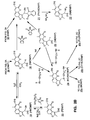
- FIG. 2 sets forth a compound synthesis scheme of the present invention where the starting material is resorcinol.
- FIG. 3 schematically shows the steps involved in screening activation compounds for sterilizing compounds.
- FIG. 4 schematically shows the steps involved in amplifying nucleic acid according to one particular amplification system.
- FIG. 5 schematically shows a manner of determining compound solubility.
- FIG. 6 is a perspective view of an embodiment (CE-I) of the photoactivation device of the present invention.
- FIG. 7 is a cross-sectional view of CE-I along lines a—a of FIG. 6 .
- FIG. 8 is a cross-sectional view of CE-I along lines b—b of FIG. 6 .
- FIG. 9 is a perspective view of an alternative embodiment (CE-II) of the photoactivation device of the present invention.
- FIG. 10 is a cross-sectional view of CE-II along lines c—c of FIG. 9 .
- FIG. 11 is a perspective view of yet another alternative embodiment (CE-III) of the photoactivation device of the present invention.
- FIG. 12 is a cross-sectional view of CE-III along lines d—d of FIG. 11 .
- FIG. 13 is a cross-sectional view of CE-III along lines e—e of FIG. 11 .
- FIG. 14 is a perspective view of a removable sample tray for processing large numbers of samples.
- FIG. 15 shows the impact of irradiation time on temperature of the sample.
- FIG. 16 shows the relative energy output of the alternative embodiments of the device of the present invention.
- FIG. 17 is a flow chart schematically showing a manner of measuring binding.
- FIG. 18 shows covalent binding according to particular embodiment of the photoactivation device of the present invention.
- FIG. 19 shows the intensity of the light of one embodiment of the device of the present invention according to sample position.
- FIG. 20 shows covalent binding according to sample position.
- FIG. 21 shows schematically a manner of measuring production of photoproduct.
- FIG. 22 shows the production of photoproduct over time.
- FIG. 23 show production of photoproduct according to the embodiment of the photoactivation device of the present invention.
- FIG. 24 show production of photoproduct from a novel compound of the present invention.
- FIG. 25 shows binding as a function of concentration.
- FIG. 26 shows the oligonucleotide system used for the synthesis and extension of 71-mers containing a single monoadduct.
- FIG. 27 shows a manner of synthesizing monoadducted templates.
- FIG. 28 shows a manner of measuring primer extension.
- FIG. 29 is an autoradiograph after gel electrophoresis, showing polymerase inhibition results with MIP.
- FIG. 30 is an autoradiograph after gel electrophoresis, showing polymerase inhibition results with AMIP.
- FIG. 31 is an autoradiograph after gel electrophoresis, showing polymerase inhibition results with AMDMIP.
- FIG. 32 is an autoradiograph after gel electrophoresis, showing Tag polymerase inhibition results with AMIP, AMDMIP, and MIP 71-mer monoadducts.
- FIG. 33 is an autoradiograph after gel electrophoresis, showing Tag polymerase inhibition results with AMIP, AMDMIP, and MIP 71-mer monoadducts after repeated cycles.
- FIG. 34 is an autoradiograph after gel electrophoresis, showing inhibition results of HPLC repurified 5-MIP monoadduct.
- FIG. 35 is an autoradiograph after gel electrophoresis, showing Tag polymerase inhibition results with an HMT 71-mer-monoadduct.
- FIG. 36 shows the oligonucleotide system for amplification and subsequent detection of HIV DNA.
- FIG. 37 is an autoradiograph after gel electrophoresis, showing sterilization of PCR with photoproduct.
- FIG. 38 is a plot of counts (CPM) from bands cut after gel electrophoresis, showing sterilization of PCR according to concentration of photoproduct.
- FIG. 39 is an autoradiograph after gel electrophoresis, showing sterilization of PCR according to the photoactivation device used.
- FIG. 40 shows schematically a manner of measuring PCR sterilization according to cycle number.
- FIG. 41 is an autoradiograph after gel electrophoresis, PCR sterilization according to cycle number.
- FIG. 42 shows schematically a preferred manner of measuring PCR sterilization.
- FIG. 43 is an autoradiograph after gel electrophoresis, showing a PCR sterilization.
- FIG. 44 shows plotted counts of PCR product bands that were visualized by autoradiography, cut, and counted in a liquid scintillation counter, illustrating the effect of modification density and target length on sterilization.
- FIG. 45 shows schematically two different hybridization formats: 1) Oligonucleotide Hybridization (OH) and 2) Crosslinkable Oligonucleotide Probe Analysis (COP).
- OH Oligonucleotide Hybridization
- COP Crosslinkable Oligonucleotide Probe Analysis
- FIG. 46 is an autoradiograph after gel electrophoresis, showing hybridization after sterilization by Crosslinkable Oligonucleotide Probe Analysis (COP.
- FIG. 47 is an autoradiograph after gel electrophoresis, showing hybridization after sterilization by Oligonucleotide Hybridization (OH).
- FIG. 48 is an autoradiograph after gel electrophoresis, showing PCR sterilization of an HLA DNA system.
- FIG. 49 is an autoradiograph after gel electrophoresis, showing inhibition of PCR with non-furocoumarin compounds.
- the present invention relates to a device and method for photoactivating new and known compounds.
- the description of the invention is divided into I) Compound Synthesis, II) Photoactivation Devices and Methods, III) Binding of Compounds to Nucleic Acid, IV) Capture of Nucleic Acid, V) Inhibiting Template-Dependent Enzymatic Synthesis, and VI) Sterilization.
- Activation compounds defines a family of compounds that undergo chemical change in response to triggering stimuli. Triggering stimuli include, but are not limited to, thermal stimuli, chemical stimuli and electromagnetic stimuli. “Photoreactive, activation compounds” (or simply “photoreactive compounds”), defines a genus of compounds in the activation compound family that undergo chemical change in response to electromagnetic radiation (Table 1). One species of photoreactive compounds
- the furocoumarins belong to two main categories: 1) psoralens [7H-furo(3,2-g)-(1)-benzopyran-7-one, or ⁇ -lactone of 6-hydroxy-5-benzofuranacrylic acid], which are linear:
- FIGS. 1 and 2 set forth the overall scheme for the synthesis of the furocoumarin derivatives of the present invention.
- FIGS. 1 and 2 set forth how each furocoumarin derivative may be labelled. Where both an unlabelled and radiolabelled version of a compound may be synthesized by methods of the present invention, the radiolabel is indicated in parentheses.
- the compounds will have at least one label attached or integrated into its structure.
- Labels are generally intended to facilitate i) the detection of the inhibiting compounds, as well as ii) the detection of molecules bound to the inhibiting compounds (e.g. nucleic acid). Labels are chosen from the group consisting of enzymes, fluorophores, high-affinity conjugates, chemiphores and radioactive atoms (“radiolabels”).
- enzymes contemplated include alkaline phosphatase, ⁇ -galactosidase and glucose oxidase, 2) an affinity conjugate system contemplated is the biotin-avidin system, 3) fluorescein is contemplated as a fluorophore, 4) luminol is contemplated as chemiphore, and 4) the preferred radiolabels contemplated by the present invention include 3 H and 14 C.
- the present invention contemplates single labelling (e.g. a radiolabel, a fluorophore, etc.) and double labelling
- a preferred label of the present invention for facilitating the detection of compounds is tritium ( 3 H).
- a preferred label of the present invention for facilitating the detection of molecules bound to the compounds is biotin. While FIGS. 1 and 2 have been drafted to show these preferred labels (as well as some other labels), it is not intended thereby to limit the present invention.
- R is either —CH 3 or —H, respectively.
- R is —CH 3 (FIG. 1; Table 2)
- the starting compound is 5-methylresorcinol.
- R is —H (FIG. 2; Table 3)
- the starting compound is resorcinol. Accordingly, the description of the compound synthesis methods of the present invention proceeds in two parts.
- the synthesis can continue on to create i) new compounds XMIP (Compound #5), HMIP (Compound #6), FMIP (Compound #7), IMIP (Compound #8), HMTAMIP (Compound #9), AMIP (Compound #10), DMHMIP (Compound #11), BIOMIP (Compound #12a), DITHIOMIP (Compound 12b), and/or FLUORMIP (Compound 12c), or ii) radiolabelled compounds.
- radiolabels are indicated in parathesis where the compound can be synthesised unlabelled as well as labelled.
- the analogous 14 C derivatives may be prepared 14 C labelled 5-methylresorcinol.
- the invention contemplates novel approaches to the synthesis of MIP and/or labelled MIP prior to the synthesis of novel MIP derivatives.
- the first step of the first method for MIP synthesis involves a reaction of 5-methylresorcinol with malic acid to yield H5MC (Compound #1).
- the second step of the first method involves a reaction of H5MC with a haloacetaldehyde diethylacetal to yield the diethoxyethylether of H5MC, DEMC (Compound #2).
- the haloacetaldehyde diethylacetal can be chloro-, iodo- or bromo-acetaldehyde diethylacetal.
- DEMC is treated to close the ring to yield the two isomers, 5-methylpsoralen and MIP, which are separated to isolate pure MIP (Compound #3).
- the first step of the second method for MIP synthesis is identical to the first step of the first method.
- the second step of the second method involves the synthesis of MIP directly from H5MC (i.e., compound #2 to #3) via a haloethylene carbonate.
- THMIP 3,4,4′,5′-tetrahydro-[ 3 H 4 ]-5-methylisopsoralen
- the present invention contemplates that the catalyst is selected from the group consisting of palladium on charcoal, palladium on barium sulfate, Adams catalyst [(NH 4 ) 2 PtCl 6 ], PtO 2 , rhoduim, ruthenium, copper chromite and Raney nickel.
- the present invention contemplates that the hydrogen donor in the reoxidation step is selected from the group consisting of diphenylether and cyclohexene.
- XMIP is defined a halomethylisopsoralen selected from the group consisting of bromomethylisopsoralen (BMIP) and chloromethylisopsoralen (CMIP).
- the synthesis method of XMIP of the present invention is a free radical halogenation of MIP with an N-halosuccinimide and a peroxide initiator.
- the preferred N-halosuccinimide is N-bromosuccinimide but the present invention contemplates the use of N-chlorosuccinimide as well.
- the present invention contemplates radiolabelled XMIP.
- Methods are provided for the synthesis of radiolabelled XMIP (FIG. 1 ).
- the method builds on the methods of synthesizing radiolabelled MIP (e.g. #3 to #4, #4* to #3*, and #3* to #5*, where * indicates a radiolabelled compound).
- the methods proceed via new compounds HMIP and FMIP (e.g. #5 to #6, #6 to #7, #7 to #6*, and #6* to #5*, where * indicates a radiolabelled compound).
- Combining the radiolabelling steps for MIP with the HMIP/FMIP radiolabelling method provides for double-radiolabelling of XMIP (e.g., #3 to #4*, #4* to #3*, and #3* to #5*, #5* to #6*, #6* to #7*, #7* to #6**, and #6** to #5**, where ** indicates a double-radiolabelled compound).
- XMIP e.g., #3 to #4*, #4* to #3*, and #3* to #5*, #5* to #6*, #6* to #7*, #7* to #6**, and #6** to #5**, where ** indicates a double-radiolabelled compound).
- XMIP bromomethylisopsoralen
- CMIP chloromethylisopsoralen
- XMIP may be the same halomethylisopsoralen or may be a different isopsoralen.
- XMIP may be the same halomethylisopsoralen or may be a different isopsoralen.
- the reactivity of XMIP will increase as X is changed from chloro to bromo; a significant advantage of higher reactivity is correspondingly shorter reaction times for conversions such as XMIP ⁇ HMIP.
- the synthesis proceeds via IMIP.
- benzyl iodides are more reactive than the corresponding bromides or chlorides, which follows from the relative ability of each halide to act as a leaving group in an S N 2 (second order, nucleophilic displacement) reaction. Accordingly, to take advantage of the resulting high reactivity and corresponding short reaction times provided by the benzyl iodide analog, the new compound IMIP is prepared in the method of the present invention via the Finkelstein reaction.
- the present invention provides eight methods for synthesizing AMIP from 5-methylresorcinol:
- IV #1 to #3, #3 to #5, #5 to #9, and #9 to #10 V #1 to #2, #2 to #3, #3 to #5, #5 to #8, #8 to #9, and #9 to #10.
- FIG. 1 also shows two methods provided for proceeding via new compound intermediate XMIP as starting material to new compound, radiolabelled AMIP. Both of the methods proceeding via new compound intermediate XMIP as starting material to new compound, radiolabelled AMIP, proceed via HMIP and new compound FMIP.
- One method is a six step method (i.e., compound #5 to #6, #6 to #7, #7 to #6*, #6* to #5*, #5* to #9*, and #9* to #10*); the other is a seven step method (i.e., compound #5 to #6, #6 to #7, #7 to #6*, #6* to #5*, #5* to #8*, #8* to #9*, and #9* to #10*).
- the present invention When combined with the two methods for producing MIP, the present invention provides two additional methods (for a total of four methods) for synthesizing radiolabelled AMIP from 5-methyl-resorcinol; when combined with the two methods for producing radiolabelled MIP, the present invention provides eight additional methods for producing radiolabelled AMIP for a total of twelve methods:
- the present invention also contemplates double-labelling.
- the double-labelling method of the present invention involves the combination of the labelling steps for MIP (Compound #3 to Compound #4) and the labelling steps for AMIP.
- the label is a radiolabel
- the present invention contemplates the following double-radiolabelling methods (where ** indicates a double-labelled compound):
- BIO-, DITHIO- and FLUOR-derivatives of MIP of the present invention can each be generally described as a three part compound consisting of the following three units:
- the spacer contemplated by the present invention has the general formula R 1 HN—(CH 2 ) n —NHR 2 .
- R 1 —H, —CH 3 , —C 2 H 5 , —C 3 H 7 or —C 4 H 9
- R 2 —H or —CH 3 , —C 2 H 5 , —C 3 H 7 or —C 4 H 9
- n is between 6 and 16, inclusive. It is contemplated that, where the BIOMIP compound is bound to another molecule (e.g. nucleic acid), sufficient length is provided for the biotin moiety to span the distance between the site of attachment to another molecule and the avidin binding site when n ⁇ 6.
- biotin binding site is reported to be 9 ⁇ below the surface of the avidin molecule [Green et al., Biochem. J. 125:781 (1971)]
- shorter spacers may hinder the formation of the biotin-avidin complex.
- Adequate chain length helps reduce steric hinderance associated with the avidin-biotin interaction, and accordingly, the stability of the avidin-biotin complex should increase when the appropriate chain length is employed.
- R 1 HN—(CH 2 ) n —NHR 2 R 1 can be —H, —CH 3 , —C 2 H 5 , —C 3 H 7 or —C 4 H 9
- R 2 can be —H, —CH 3 , C 2H 5 , C 3 H 7 or C 4 H 9 , most preferably R 1 and R 2 are both —CH 3 , C 2H 5 , —C 3 H 7 or C 4 H 9 .
- the spacer nitrogens can react at either nitrogen with only one or two equivalents of XMIP (or IMIP).
- the present invention contemplates that a high ratio of spacer to XMIP (or IMIP) is employed in the reaction. Nonetheless, even where 1) R 1 and R 2 are both —CH 3 , —C 2 H 5 , —C 3 H 7 or —C 4 H 9 , and 2) a high ratio of spacer to XMIP (or IMIP) is employed, the present invention contemplates side products from the reaction of more than one XMIP (or IMIP) with the spacer. These side products include one di-N,N-substituted product (i.e.
- R 1 and R 2 are —H. While this spacer can be used, the number of possible multi-substituted spacer side products is increased, making subsequent purification of the desired mono-N-substituted product (i.e. DMHMIP) more difficult.
- the label on the BIO-, DITHIO- and FLUOR-derivatives of MIP of the present invention is comprised of two elements: 1) the reporter moiety, and 2) the linking arm which binds the reporter moiety to the spacer.
- Two types of reporter moieties are shown in FIG. 1 .
- the first, biotin, is an indirect reporter moiety, as it functions to bind avidin, which in turn is attached to the signal generating system (e.g., BluGENE; BRL).
- the second, fluorescein is a direct reporter moiety which provides a highly fluorescent signal upon excitation with appropriate wavelengths of light.
- both biotin and fluorescein are appended to the spacer via an amide bond, with zero to seven bridging atoms making up the linking arm between the spacer amido carbonyl and the reporter moiety.
- the linking arm may contain a disulfide linkage, which is useful for subsequent cleavage of the reporter moiety from the isopsoralen.
- the reaction to form the amide bond between the spacer nitrogen and the label carbonyl uses an activated ester, preferably the N-hydroxy-succinimide ester.
- activated ester preferably the N-hydroxy-succinimide ester.
- Other active esters are contemplated, such as the imidazolides (from N,N′-carbonyldiimidizoles) and the sulfosuccinimidyl esters.
- the present invention contemplates four alternative synthesis methods for proceeding via new compound intermediate XMIP to new compound BIOMIP (Compound #12a).
- Two of the four methods proceed via HMIP; one proceeds from HMIP via IMIP (i.e., #5 to #6, #6 to #5, #5 to #8, #8 to #11, and #11 to #12a) and one proceeds from HMIP via DMHMIP (i.e., #5 to #6, #6 to #5, #5 to #11, and #11 to #12a).
- IMIP i.e., #5 to #6, #6 to #5, #5 to #11, and #11 to #12a
- DMHMIP i.e., #5 to #6, #6 to #5, #5 to #11, and #11 to #12a
- the other two methods proceed directly from XMIP (i.e.
- HMIP without HMIP
- IMIP i.e., #5 to #8, #8 to #11, and #11 to #12a
- DMHMIP i.e., #5 to #11, and #11 to #12a
- the routes via HMIP offer the advantage of allowing for interruptions in the synthesis (often necessary in a production facility) because of the stability of HMIP.
- the XMIP route is more direct, however, and should be used where continued synthesis is possible.
- the present invention provides eight methods for synthesizing BIOMIP (methods III and IV are preferred):
- the present invention further contemplates synthesis methods for proceeding via new compound intermediate XMIP to radiolabelled BIOMIP. Both methods involve synthesis of HMIP and labelled HMIP.
- IMIP i.e., #5 to #6, #6 to #7, #7 to #6*, #6* to #5*, #5* to #8*, #8* to #11*, and #11* to #12a*
- DMHMIP i.e., #5 to #6, #6 to #7, #7 to #6*, #6* to #5*, #5* to #11*, and #31* to #12a*.
- BIOMIP When combined with the two methods to produce MIP and two methods to produce labelled MIP, the present invention provides twelve methods for synthesizing radiolabelled BIOMIP (methods V, VI, IX and X are preferred):
- BIOMIP twelve methods of radiolabelling BIOMIP offer one approach to double-labelling (the compound has both 3 H and biotin).
- AMIP the present invention also contemplates double-radiolabelling of BIOMIP (in this case, however, to create a triple-labelled compound).
- the double-radiolabelling method combines the radiolabelling steps for MIP with the radiolabelling steps for BIOMIP.
- the present invention contemplates four alternative synthesis methods for proceeding via new compound intermediate XMIP to new compound DITHIOMIP (Compound #12b).
- two of the four methods proceed via HMIP; one proceeds from HMIP via IMIP (i.e., #5 to #6, #6 to #5, #5 to #8, #8 to #11, and #11 to #12b) and one proceeds from HMIP via DMHMIP (i.e., #5 to #6, #6 to #5, #5 to #11, and #11 to #12b).
- IMIP i.e., #5 to #6, #6 to #5, #5 to #11, and #11 to #12b
- DMHMIP i.e., #5 to #6, #6 to #5, #5 to #11, and #11 to #12b
- the other two methods proceed directly from XMIP (i.e.
- HMIP without HMIP
- IMIP i.e., #5 to #8, #8 to #11, and #11 to #12b
- DMHMIP i.e., #5 to #11, and #11 to #12b
- the present invention provides eight methods for synthesizing DITHIOMIP (methods III and IV are preferred):
- the present invention further contemplates synthesis methods for proceeding via new compound intermediate,XMIP to radiolabelled DITHIOMIP. Both methods involve synthesis of HMIP and labelled HMIP.
- IMIP i.e., #5 to #6, #6 to #7, #7 to #6*, #6* to #5*, #5* to #8*, #8* to #11*, and #11* to #12b*
- DMHMIP i.e., #5 to #6, #6 to #7, #7 to #6*, #6* to #5*, #5* to #11*, and #11* to #12b*.
- the present invention provides twelve methods for synthesizing radiolabelled DITHIOMIP (methods V, VI, IX and X are preferred):
- DITHIOMIP twelve methods of radiolabelling DITHIOMIP offer one approach to double-labelling (the compound has both 3 H and cleavable biotin).
- BIOMIP the present invention also contemplates double-radiolabelling of DITHIOMIP (creating a triple-labelled compound).
- the double-radiolabelling method combines the radiolabelling steps for MIP with the radiolabelling steps for DITHIOMIP.
- the present invention contemplates four alternative synthesis methods for proceeding via new compound intermediate XMIP to new compound FLUORMIP (Compound #12c). As with both BIOMIP and DITHIOMIP, two of the four methods proceed via HMIP; the other two methods proceed directly from XMIP. When combined with the two methods for synthesizing MIP, the present invention provides eight methods for synthesizing FLUORMIP (methods III and IV are preferred):
- the present invention further contemplates synthesis methods for proceeding via new compound intermediate XMIP to radiolabelled FLUORMIP. As with BIOMIP and DITHIOMIP, both methods involve synthesis of HMIP and labelled HMIP.
- the present invention provides twelve methods for synthesizing radiolabelled FLUORMIP (methods V, VI, IX and X are preferred):
- the present invention also contemplates double-radiolabelling of FLUORMIP to create a triple-labelled compound.
- the double-radiolabelling method combines the radiolabelling steps for MIP with the radiolabelling steps for FLUORMIP.
- the present invention provides a two and a three step method for MIP synthesis (see FIG. 1 ).
- the overall yields of these methods of the present invention are approximately 8.4% and 7.1%.
- the methods of the present invention for MIP synthesis involve fewer steps and a better overall yield.
- the present invention contemplates a novel synthesis method for DMIP (Compound #16), a known compound; the method proceeds via new compounds XAMC (Compound #14) and RXAMC (Compound #15). From DMIP, the synthesis builds on the novel synthesis to yield known compound AMDMIP (Compound #22) or proceeds to new compounds HDMADMIP (Compound #24), BIODMIP (compound #25a), DITHIODMIP (compound #24b), FLUORDMIP (compound #24c). New methods for radiolabelling compounds are also shown. In addition to the tritiated compounds indicated in FIG. 2, the analogous 14 C derivatives may be prepared from labelled 5-methylresorcinol.
- the present invention provides a new synthesis method for DMIP.
- the approach utilizes a Claisen rearrangement to build the furan ring. This approach has heretofore only been used for synthesizing psoralens. See D. R. Bender et al., J. Org. Chem. 44:2176 (1979). D. R. Bender et al., U.S. Pat. No. 4,398,031.
- DMIP is prepared in three steps: 1) 0-alkylation with a 2,3-dihaloalkene, 2) Claisen rearrangement to provide the two allylic isomers (6-allyl and 8-allyl), and 3) ring closure to provide DMIP.
- the overall three step yield is 26%.
- the method of the new synthesis improves the prior procedure as follows.
- an alkyl anhydride is used during the Claisen rearrangement, which provides the esterified phenol (instead of esterifying as a separate step). Esterification concomitant with rearrangement enhances the yield of the rearranged product due to protection of the phenolate from subsequent undesired high temperature oxidation. While acetic or proprionic anhydrides may be used, the higher boiling butyric anhydride is preferred because it allows the reaction temperature to remain closer to the boiling point of the solvent (diisopropylbenzene).
- the present invention uses a 2,3-dihaloalkene instead of the allyl moiety, which obviates the requirement for subsequent bromination prior to the ring closure step.
- the O-(2-halo) alkene undergoes Claisen rearrangement primarily to the 8 position of the coumarin, but distinct from the allylic moiety, the rearranged haloalkene is in fact a masked ketone.
- conversion of the haloalkene to the ketone occurs along with simultaneous acid catalyzed cleavage of the alkylester.
- the resulting phenolic ketone subsequently undergoes conversion to the ring closed compound.
- a third advantage of the new synthesis is that alkaline conditions are avoided in all steps, which eliminates loss of product due to hydrolysis of the coumarin lactone to the cis cinnimate, which undergoes subsequent (irreversible) isomerization to the thermodynamically more favored trans isomer.
- the present invention also contemplates labelled DMIP.
- a two step method is provided: 1) mixing DMIP with a catalyst, acetic acid and tritium gas to yield the tritiated compound DHDMIP, and 2) mixing DHDMIP with a catalyst and diphenyl ether to yield tritiated DMIP ( 3 H-DMIP).
- the catalyst is selected from the group consisting of palladium on charcoal, palladium on barium sulfate, Adams catalyst [(NH 4 ) 2 PtCl 6 ], PtO 2 , rhoduim, ruthenium, copper chromite and Raney nickel.
- the present invention contemplates a new approach to the synthesis of known compound AMDMIP and new compound 3 H-AMDMIP.
- the approach builds on the novel synthesis method described above for DMIP.
- AMDMIP is thereafter made in one of two ways: i) with a halomethylation step, or ii) without a halo-methylation step.
- DMIP is made by the novel synthesis method described above; AMDMIP is then made by derivatizing DMIP to provide a halomethyl derivative followed by hydrazinolysis of the corresponding phthalimidomethyl derivative (prepared by the Gabriel synthesis) with hydrazine hydrate according to the method described by F. Dall'Acqua et al., J. Med. Chem 24:178 (1981).
- the approach of the present invention has the advantage over other methods of synthesizing AMDMIP.
- the procedure reported by Baccichetti et al. (U.S. Pat. No. 4,312,883) for the synthesis of AMDMIP relies on a method of DMIP synthesis that, as discussed above, is less efficient.
- the present invention contemplates a number of variations using the halomethylation step.
- XMDMIP Compound #18
- HMDMIP Compound #19
- the present invention also contemplates two ways of proceeding to AMDMIP without HMDMIP:
- the halomethylation route for the synthesis of AMDMIP can further be used to synthesize labelled AMDMIP.
- radiolabelled AMDMIP is synthesized via new compound FDMIP (Compound #20).
- FDMIP new compound FDMIP
- the present invention provides the following four (single) radiolabelling methods for AMDMIP (methods I and III are preferred):
- FIG. 2 shows two ways for synthesizing double-radiolabelled AMDMIP.
- the present invention contemplates conversion of DMIP to PHIMDMIP by direct phthalimidomethylation of the 4′ furan position with a nitrogen donor.
- the present invention contemplates that the nitrogen donor may be selected from the group consisting of N-hydroxymethyl phthalimide and derivatives thereof.
- the present invention adapts and modifies a procedure that has heretofore only been used for psoralens. N. D. Heindel et al., J. Hetero. Chem. 22:73 (1985).
- the present invention contemplates that this adapted and modified procedure is suitable for isopsoralens which a) do contain a methyl group at the 4 position, and b) do not contain hydroxy, amino or other like substituents which result in poly-substitution.
- the route for the synthesis of AMDMIP without halomethylation can further be used to synthesize labelled AMDMIP via radiolabelled DMIP.
- the present invention provides the following single radiolabelling method for AMDMIP without halomethylation:
- BIO-, DITHIO- and FLUOR-derivatives of DMIP of the present invention can each be generally described as a three part compound consisting of the following three units:
- the spacer contemplated by the present invention has the general formula R 1 HN—(CH 2 ) n —NHR 2 .
- R 1 —H, —CH 3 , —C 2 H 5 , —C 3 H 7 or —C 4 H 9
- R 2 —H, —CH 3 , —C 2 H5, —C 3 H 7 or —C 4 H 9
- n is between 6 and 16, inclusive.
- the BIODMIP compound is bound to another molecule (e.g. nucleic acid)
- sufficient length is provided for the biotin moiety to span the distance between the site of attachment to another molecule and the avidin binding site when n ⁇ 6.
- R 1 HN—(CH 2 ) n —NHR 2 R 1 can be —H, —CH 3 , —C 2 H 3 , —C 2 H 5 , —C 3 H 6 or —C 4 H 7
- R 2 can be —H, —CH 3 , —C 2 H 5 , —C 3 H 7 or —C 4 H 9
- R 1 and R 2 are both —CH 3 , —C 2 H 5 , —C 3 H 7 or —C 4 H 9 .
- the spacer nitrogens can react at either nitrogen with only one or two equivalents of XMDMIP (or IMDMIP).
- the present invention contemplates that a high ratio of spacer to XMDMIP (or IMDMIP) is employed in the reaction. Nonetheless, even where 1) R 1 and R 2 are both —CH 3 , —C 2 H 5 , —C 3 H 7 or —C 4 H 9 and 2) a high ratio of spacer to #XMDMIP (or IMDMIP) is employed, the present invention contemplates side products from the reaction of more than one XMDMIP (or IMDMIP) with the spacer. These side products include one di-N,N-substituted product (i.e.
- R 1 and R 2 are —H. While this spacer can be used, the number of possible multi-substituted spacer side products is increased, making subsequent purification of the desired mono-N-substituted product (i.e. HDAMDMIP) more difficult.
- the label on the BIO-, DITHIO- and FLUOR-derivatives of DMIP of the present invention is comprised of two elements: 1) the reporter moiety, and 2) the linking arm which binds the reporter moiety to the spacer.
- Two types of reporter moieties are shown in FIG. 2 : i) biotin and ii) fluorescein. Both biotin and fluorescein are appended to the spacer via an amide bond, with zero to seven bridging atoms making up the linking arm between the spacer amido carbonyl and the reporter moiety.
- the linking arm may contain a disulfide linkage, which is useful for subsequent cleavage of the reporter moiety from the isopsoralen.
- the reaction to form the amide bond between the spacer nitrogen and the label carbonyl uses an activated ester, preferrably the N-hydroxy-succinimide ester.
- activated ester preferrably the N-hydroxy-succinimide ester.
- Other active esters are contemplated, such as the imidazolides (from N,N′-carbonyldiimidizoles) and the sulfosuccinimidyl esters.
- the present invention contemplates four alternative synthesis methods for proceeding via new compound intermediate XMDMIP to new compound BIODMIP (Compound #25a). Two of the four methods proceed via HMDMIP:
- the present invention also provides methods for radiolabelling BIODMIP. Two methods are provided for synthesizing radiolabelled BIODMIP from DMIP and two methods are provided for synthesizing (single) radiolabelled BIODMIP from radiolabelled DMIP, for a total of four (single) radiolabelling methods:
- the present invention also contemplates double-radiolabelling of BIODMIP.
- FIG. 2 shows two methods of double-radiolabelling BIODMIP.
- the double-radiolabelling method of the present invention involves the combination of the radiolabelling steps for DMIP (Compound #16 to Compound #17*) and the radiolabelling steps for BIODMIP (above). As noted, this provides, among other advantages, the advantage of increasing the specific activity of the compounds of the present invention.
- the present invention contemplates the following double-radiolabelling methods (where ** indicates a double-labelled compound):
- the present invention contemplates four alternative synthesis methods for proceeding via new compound intermediate XMDMIP to new compound DITHIODMIP (Compound #25b). Two of the four methods proceed via HMDMIP:
- the present invention also provides methods for radiolabelling DITHIODMIP. Two methods are provided for synthesizing radiolabelled DITHIODMIP from DMIP and two methods are provided for synthesizing (single) radiolabelled DITHIODMIP from radiolabelled DMIP, for a total of four (single) radiolabelling methods:
- the present invention also contemplates double-radiolabelling of DITHIODMIP.
- FIG. 2 shows two methods of double-radiolabelling DITHIODMIP.
- the double-radiolabelling method of the present invention involves the combination of the radiolabelling steps for DMIP (Compound #16 to Compound #17*) and the (single) radiolabelling steps for DITHIODMIP (above).
- this provides, among other advantages, the advantage of increasing the specific activity of the compounds of the present invention.
- the present invention contemplates the following double-radiolabelling methods (where ** indicates a double-labelled compound):
- the present invention contemplates four alternative synthesis methods for proceeding via new compound intermediate XMDMIP to new compound FLUORDMIP (Compound #25c). Two of the four methods proceed via HMDMIP:
- the present invention also provides methods for radiolabelling FLUORDMIP. Two methods are provided for synthesizing radiolabelled FLUORDMIP from DMIP and two methods are provided for synthesizing (single) radiolabelled FLUORDMIP from radiolabelled DMIP, for a total of four (single) radiolabelling methods:
- the present invention also contemplates double-radiolabelling of FLUORDMIP.
- FIG. 2 shows two methods of double-radiolabelling FLUORDMIP.
- the double-radiolabelling method of the present invention involves the combination of the radiolabelling steps for DMIP (Compound #16 to Compound #17*) and the radiolabelling steps for FLUORDMIP (above).
- the present invention contemplates the following double-radiolabelling methods (where ** indicates a double-labelled compound):
- the present invention contemplates devices and methods for photoactivation and specifically, for activation of photoreactive compounds.
- the present invention contemplates devices having an inexpensive source of electromagnetic radiation that is integrated into a unit.
- the present invention contemplates a photoactivation device for treating photoreactive compounds, comprising: a) means for providing appropriate wavelengths of electromagnetic radiation to cause activation of at least one photoreactive compound; b) means for supporting a plurality of sample vessels in a fixed relationship with the radiation providing means during activation; and c) means for maintaining the temperature of the sample vessels within a desired temperature range during activation.
- the present invention also contemplates methods for photoactivating, comprising: a) supporting a plurality of sample vessels, containing one or more photoreactive compounds, in a fixed relationship with a fluorescent source of electromagnetic radiation; b) irradiating the plurality of sample vessels simultaneously with said electromagnetic radiation to cause activation of at least one photoreactive compound; and c) maintaining the temperature of the sample vessels within a desired temperature range during activation.
- the devices of the present invention serve to replace the specialized instruments of photochemists investigating basic photochemistry of a photoactivator in vitro.
- These specialized instruments have expensive, high energy, light sources such as high pressure arc lamps or medium pressure mercury lamps.
- each has its own peculiar sample holders with varying geometries relative to the lamp source and with varying filter devices (eg. glass cut-off filters or liquid solutions that transmit only a specific region of the electromagnetic spectrum or ultraviolet spectrum).
- filter devices eg. glass cut-off filters or liquid solutions that transmit only a specific region of the electromagnetic spectrum or ultraviolet spectrum.
- the major features of one embodiment of the device of the present invention involve: A) an inexpensive source of ultraviolet radiation in a fixed relationship with the means for supporting the sample vessels, B) rapid photoactivation, C) large sample processing, D) temperature control of the irradiated samples, and E) inherent safety.
- a preferred photoactivation device of the present invention has an inexpensive source of ultraviolet radiation in a fixed relationship with the means for supporting the sample vessels.
- Ultraviolet radiation is a form of energy that occupies a portion of the electromagnetic radiation spectrum (the electromagnetic radiation spectrum ranges from cosmic rays to radio waves).
- Ultraviolet radiation can come from many natural and artificial sources. Depending on the source of ultraviolet radiation, it may be accompanied by other (non-ultraviolet) types of electromagnetic radiation (e.g. visible light).
- Wavelength is herein described in terms of nanometers (“nm”; 10 ⁇ 9 meters). For purposes herein, ultraviolet radiation extends from approximately 180 nm to 400 nm.
- a radiation source does not emit radiation below a particular wavelength (e.g. 300 nm), it is said to have a “cutoff” at that wavelength (e.g. “a wavelength cutoff at 300 nanometers”).
- UV radiation is herein described in terms of irradiance, it is expressed in terms of intensity flux (milliwatts per square centimeter or “mW cm ⁇ 2” ).
- Output is herein defined to encompass both the emission of radiation (yes or no; on or off) as well as the level of irradiance.
- a preferred source of ultraviolet radiation is a fluorescent source.
- Fluorescence is a special case of luminescence. Luminescence involves the absorption of electromagnetic radiation by a substance and the conversion of the energy into radiation of a different wavelength. With fluorescence, the substance that is excited by the electromagnetic radiation returns to its ground state by emitting a quantum of electromagnetic radiation. While fluorescent sources have heretofore been thought to be of too low intensity to be useful for photoactivation, in one embodiment the present invention employs fluorescent sources to achieve results thus far achievable on only expensive equipment.
- fixed relationship is defined as comprising a fixed distance and geometry between the sample and the light source during the sample irradiation.
- Distance relates to the distance between the source and the sample as it is supported. It is knows that light intensity from a point source is inversely related to the square of the distance from the point source. Thus, small changes in the distance from the source can have a drastic impact on intensity. Since changes in intensity can impact photoactivation results, changes in distance are avoided in the devices of the present invention. This provides reproducibility and repeatability.
- Geometry relates to the positioning of the light source. For example, it can be imagined that light sources could be placed around the sample holder in many ways (on the sides, on the bottom, in a circle, etc.).
- the geometry used in a preferred embodiment of the present invention allows for uniform light exposure of appropriate intensity for rapid photoactivation.
- the geometry of a preferred device of the present invention involves multiple sources of linear lamps as opposed to single point sources. In addition, there are several reflective surfaces and several absorptive surfaces. Because of this complicated geometry, changes in the location or number of the lamps relative to the position of the samples to be irradiated are to be avoided in that such changes will result in intensity changes.
- the light source of the preferred embodiment of the present invention allows for rapid photoactivation.
- the intensity characteristics of the irradiation device have been selected to be convenient with the anticipation that many sets of multiple samples may need to be processed. With this anticipation, a fifteen minute exposure time is a practical goal.
- a fifteen minute exposure in addition to its convenience, provides for reproducible results.
- the binding levels of photoactive compounds to polynucleotides increases with increasing exposure to activating light.
- a plateau of binding density is ultimately achieved. This plateau results from competing photochemical reactions.
- Most photoreactive compounds which undergo addition reactions to the base moieties of nucleic acid also undergo photodecomposition reactions when free in solution.
- intensity flux watts/cm 2
- the relative rates of these competing reactions will determine when, in the course of a time course of an irradiation process, the plateau level will be achieved.
- Plateau levels of binding will avoid minor intensity differences that can arise from small differences in sample position (i.e. while the means for supporting the sample vessels can be in a fixed relationship with the source of irradiation, each sample in a large number of samples cannot occupy precisely the same point in space relative to the source). When plateau binding is used, identical reaction mixtures in different positions will show the same level of binding.
- the present invention contemplates for a preferred device: a) a fluorescent source of ultraviolet radiation, and b) a means for supporting a plurality of sample vessels, positioned with respect to the fluorescent source, so that, when measured for the wavelengths between 300 and 400 nanometers, an intensity flux greater than 15 mW cm ⁇ 2 is provided to the sample vessels.
- the following steps are contemplated: a) providing a fluorescent source of ultraviolet radiation, and b) supporting a plurality of sample vessels with respect to the fluorescent source of ultraviolet radiation, so that, when measured for the wavelengths between 300 and 400 nanometers, an intensity flux greater than 15 mW cm ⁇ 2 is provided simultaneously to the plurality of sample vessels, and c) simultaneously irradiating the plurality of sample vessels.
- one element of the devices of the present invention is a means for supporting a plurality of sample vessels.
- the supporting means comprises a sample rack detachably coupled to the housing of the device.
- the sample rack provides a means for positioning the plurality of sample vessels.
- the positioning means has been designed to be useful in combination with commonly used laboratory sample vessels.
- Commonly used laboratory sample vessels include, but are not limited to, test tubes, flasks, and small volume (0.5-1.5 ml) plastic tubes (such as Eppendorph tubes).
- the detachable aspect of the sample rack in the preferred embodiment also provides for interchange-ability of the supporting means. Sample racks halving different features suited to different size sample vessels and/or different size photoactivation jobs can be interchanged freely.
- the embodiments of the device of the present invention also provide for the processing of a large liquid sample.
- a trough is provided for holding temperature control liquid (see next section).
- the trough serve as a built-in container for liquid that is to be irradiated.
- the device of the present invention provides a flow-through trough, having inlet and outlet ports for liquid. It is contemplated that the flow-through trough serve as a container for continuous liquid flow during irradiation. Temperature control of this flow-through system can still be achieved by use of an external temperature control means (e.g. a temperature controlled reservoir).
- Temperature control is important because the temperature of the sample in the sample vessel at the time of exposure to light can dramatically impact the results.
- conditions that promote secondary structure in nucleic acids also enhance the affinity constants of many psoralen derivatives for nucleic acids. Hyde and Hearst, Biochemistry, 17, 1251 (1978). These conditions are a mix of both solvent composition and temperature.
- irradiation at low temperatures enhances the covalent addition of HMT to 5S rRNA bib two fold at 4° C. compared to 20° C.
- Even further temperature induced enhancements of psoralen binding have been reported with synthetic polynucleotides. Thompson et al., Biochemistry 21:1363 (1982).
- Temperature control is also an important factor for hybridization assays that detect allele specific nucleic acid targets.
- Allelic variants of a specific target nucleic acid may differ by a single base.
- Sickle cell anemia is an example of a human genetic disease that results from the change of a single base (A to T) in the gene for the human ⁇ globin molecule.
- the specific hybridization of a single oligonucleotide probe to one of two allelic variants that differ by only a single base requires very precise temperature control. Wood et al., Proc. Nat. Acad. Sci. 82:1585 (1985).
- Ultraviolet radiation can cause severe burns. Depending on the nature of the exposure, it may also be carcinogenic.
- the light source of a preferred embodiment of the present invention is shielded from the user. This is in contrast to the commercial hand-held ultraviolet sources as well as the large, high intensity sources.
- the irradiation source is contained within a housing made of material that obstructs the transmission of radiant energy (i.e. an opaque housing).
- sample vessels are placed in the sample rack which is detachably coupled to the housing above the rack.
- a sample overlay is provided that extends over and covers the sample vessels. This sample overlay provides two functions. First, it helps to maintain the position of the sample vessels when liquid is in the trough. Second, and more importantly, it closes off the only opening of the housing and, thereby, seals the device. The sealed device allows no irradiation to pass to the user. This allows for inherent safety for the user.
- the present invention contemplates binding new and known compounds to nucleic acid, including (but not limited to) a) nucleic acid target sequences, probes, and primers, as well as b) nucleic acid used as template, and c) amplified nucleic acid.
- Target sequences are regions of nucleic acid having one or more segments of known base sequence.
- Target sequences are “targets” in the sense that they are sought to be detected (i.e. sorted out from other nucleic acid). Detection is frequently performed by hybridization with probes.
- Probes are nucleic acids having a base sequence that is partially or completely complementary with all or a portion of a target sequence.
- Template is defined simply as nucleic acid that is substrate for enzymatic synthesis. Frequently, it is nucleic acid suspected of containing target sequence(s). Primers act to control the point of initiation of synthesis of target sequences when they are present in the template. Other molecular biological techniques use template and replicating probes.
- the present invention contemplates that the binding to all these forms of nucleic acid (as well as others) can be non-covalent binding and/or covalent binding.
- the present invention contemplates specific embodiments of binding including, but not limited to dark binding and photobinding.
- One embodiment of the binding of the present invention involves dark binding.
- Dark Binding is defined as binding to nucleic acid that occurs in the absence of photoactivating wavelengths of electromagnetic radiation. Dark binding can be covalent or non-covalent.
- Dark Binding Compounds are defined as compounds that are capable of dark binding.
- Photoproduct is defined as a product of the reaction of a compound and activating wavelengths of electromagnetic radiation that, once formed, is later capable of binding to nucleic acid in the absence of electromagnetic radiation.
- the present invention contemplates a radical departure from this historical approach to photobinding.
- the temporal sequence is the following: 1) providing one or more furocoumarin derivatives, 2) exposing the furocoumarin derivative(s) to activating wavelengths of electromagnetic radiation, 3) providing a particular nucleic acid sample or nucleic acid sequence, and 4) mixing the irradiated furocoumarin derivative(s) with the nucleic acid in the absence of activating wavelengths of electromagnetic radiation.
- the furocoumarin derivative is irradiated prior to mixing with nucleic acid.
- Photoaddition Product The product of this reaction is hereinafter referred to as “Photoaddition Product” and is to be distinguished from “Photoproduct.”
- the excited species may react with itself (i.e. a ground state or excited species) to create a ground state complex (“C:C”).
- C:C ground state complex
- the product of these self-reactions where two compounds react is referred to as “photodimer” or simply “dimer.”
- the self-reactions are not limited to two compounds; a variety of multimers may be formed (trimers, etc.).
- the excited species is not limited to reacting with itself. It may react with its environment, such as elements of the solvent (“E”) (e.g. ions, gases, etc.) to produce other products:
- E elements of the solvent
- excited species may undergo other reactions than described here.
- Photoproduct does not depend on which one (if any) of these reactions actually occurs.
- Photoproduct whatever its nature—is deemed to exist if, following the reaction of a compound and activating wavelengths of electromagnetic radiation, there is a resultant product formed that is later capable of binding to nucleic acid in the absence of electromagnetic radiation, i.e. capable of dark binding (whether non-covalent dark binding or covalent dark binding).
- photoproduct demands that, once formed by exposure to electromagnetic radiation, the product be “capable” of binding to nucleic acid in the absence of electromagnetic radiation, it is not necessary that the product bind only in the dark. Photoproduct may bind under the condition where there is exposure to electromagnetic radiation; it simply does not require the condition for binding. Such a definition allows for both “photobinding” and “photoproduct binding” to nucleic acid to occur at the same time. Such a definition also allows a single compound to be “photoproduct” and “photobinding compound.”
- the present invention contemplates dark binding of both psoralen photoproduct and isopsoralen photoproduct.
- psoralens such as 4′-hydroxymethyl-4,5′,8-trimethylpsoralen (HMT)
- HMT 4′-hydroxymethyl-4,5′,8-trimethylpsoralen
- the present invention contemplates there are a number of resultant products produced when the HMT is exposed to activating wavelngths of electromagnetic radiation.
- the present invention contemplates that a number of resultant products are similarly produced when isopsoralens such as AMIP and AMDMIP are exposed to activating wavelengths of electromagnetic radiation (particularly when irradiated with the CE-III device).
- the major resultant products of HMT are two cyclobutyl photodimers.
- the two pyrone rings are linked in a cis-syn configuration, while in the other dimer, the linkage occurs between the furan end of one molecule and the pyrone end of the other, again with cis-syn configuration.
- a third resultant product of HMT is a monomeric HMT photoisomer. In this isomer, the central ring oxygens assume a 1, 4 instead of the normal 1, 3 orientation. While the two photodimers would not be expected to have an intercalating activity due to geometrical considerations, the photoisomer remains planer, and accordingly, it is contemplated that it has a positive intercalative association with double stranded nucleic acid.
- Photobinding is defined as the binding of photobinding compounds in the presence of photoactivating wavelengths of light.
- Photobinding compounds are compounds that bind to nucleic acid in the presence of photoactivating wavelengths of light.
- the present invention contemplates a number of methods of photobinding, including 1) photobinding with photobinding compounds of the present invention, 2) high photobinding with new and known compounds, and 3) photobinding to label nucleic acids.
- the steps of the method comprise: a) providing a photobinding compound; b) providing one or more nucleic acid target sequences; and c) mixing the photobinding compound with the nucleic acid target sequences in the presence of photoactivation wavelengths of electromagnetic radiation.
- DEMC Compound #2
- XMIP Compound #5
- HMIP Compound #6
- a preferred embodiment of the method of the present invention for photobinding involves the steps: a) providing a photobinding compound; and b) mixing the photobinding compound with nucleic acid in the presence of photoactivation wavelengths of electromagnetic radiation, where the photobinding compound is selected from the group consisting of AMIP (Compound #10), BIOMIP (Compound #12a), DITHIOMIP (Compound #12b), FLUORMIP (Compound #12c), BIODMIP (compound #25a), DITHIODMIP (compound #25b), FLUORDMIP (compound #25c), and their radiolabelled derivatives.
- AMIP Compound #10
- BIOMIP Compound #12a
- DITHIOMIP Compound #12b
- FLUORMIP Compound #12c
- BIODMIP compound #25a
- DITHIODMIP Compound #25b
- FLUORDMIP compound #25c
- the steps of the method comprise: a) providing a photobinding compound; b) providing one or more nucleic acid target sequences; and c) mixing the photobinding compound with the nucleic acid target sequences in the presence of photoactivation wavelengths of electromagnetic radiation, where the photobinding compound is selected from the group consisting of AMIP (Compound #10), BIOMIP (Compound #12a), DITHIOMIP (Compound #12b), FLUORMIP (Compound #12c), BIODMIP (compound #25a), DITHIODMIP (compound #25b), FLUORDMIP (compound #25c), and their radiolabelled derivatives.
- the present invention contemplates a photobinding compound:nucleic acid complex, where the photobinding compound of the complex is selected from the group consisting of AMIP (Compound #10), BIOMIP (Compound #12a), DITHIOMIP (Compound #12b), FLUORMIP (Compound 12c), BIODMIP (compound #25a), DITHIODMIP (compound #25b), FLUORDMIP (compound #25c), and their radiolabelled derivatives.
- AMIP Photobinding compound:nucleic acid complex
- the invention contemplates a method for modifying nucleic acid, comprising the steps: a) providing photobinding compound and nucleic acid; and b) photobinding the photobinding compound to the nucleic acid, so that a compound:nucleic acid complex is formed, wherein the photobinding compound is selected from the group consisting of AMIP (Compound #10), BIOMIP (Compound #12a), DITHIOMIP (Compound #12b), FLUORMIP (Compound 12c), BIODMIP (compound #25a), DITHIODMIP (compound #25b), FLUORDMIP (compound #25c), and their radiolabelled derivatives.
- AMIP Compound #10
- BIOMIP Compound #12a
- DITHIOMIP Compound #12b
- FLUORMIP Compound 12c
- BIODMIP Compound #25a
- DITHIODMIP Compound #25b
- FLUORDMIP compound #25c
- the present invention provides isopsoralens with high photobinding affinity and conditions for using isopsoralens to allow for high photobinding.
- High photobinding is defined here as photobinding to nucleic acid that results in significantly higher levels of addition than reported for the known compound AMDMIP.
- the present invention provides photobinding methods for i) known isopsoralens, and ii) new isopsoralens.
- methods for known isopsoralens the present invention provides methods for photobinding of AMDMIP that allow for photobinding of AMDMIP to DNA at a level greater than 1 photobound AMDMIP per 15 base pairs, and to RNA at a level greater than 1 photobound AMDMIP per 20 RNA bases.
- photobinding methods for new isopsoralens the present invention provides photobinding methods for new compound AMIP that allow for photobinding at a level greater than 1 photobound AMIP per 15 base pairs of DNA and a level greater than 1 photobound AMIP per 20 bases of RNA.
- the photobinding methods of the present invention take into consideration two concepts as they relate to photobinding capacity: a) nucleic acid base pair/compound ratio, and b) isopsoralen structure.
- Dall'Acqua et al. compared AMDMIP photobinding with the photobinding of the parent compound, DMIP.
- the parent compound (as well as other compounds) was tested at concentrations at or near its solubility limit (i.e., DMIP was tested at 10.1 ⁇ g/ml; DMIP's maximum aqueous solubility, as reported by Dall'Acqua et al., is 8 ⁇ g/ml).
- AMDMIP was tested in this concentration range as well (specifically, at 13.1 ⁇ g/ml).
- the photobinding methods of the present invention take into consideration the nucleic acid base pair/compound ratio.
- the photobinding methods of the present invention involve carrying out the photobinding step under conditions where the isopsoralen concentration is increased relative to the concentration of nucleic acid base pairs.
- increasing the isopsoralen concentration takes advantage of the solubility of the isopsoralen; with isopsoralens which have high aqueous solubility, higher concentrations are possible to obtain.
- the present invention takes into consideration the much better solubility of AMDMIP as compared with the parent compound, DMIP. While DMIP is reported to be a better intrinsic photobinder than AMDMIP, the level of addition to nucleic acid is governed by the photobinding compound concentration (relative to nucleic acid) which is (with the concentration of nucleic acid constant) governed by solubility of the photobinding compound. Thus, while DMIP is a better intrinsic photobinder, the poor solubility of DMIP results in a relatively low level of addition (adducts per base pair) to nucleic acid.
- AMDMIP By taking advantage of the higher solubility of AMDMIP, higher concentrations of AMDMIP can be used, thus providing a higher ratio of photobinding compound to nucleic acid base pairs prior to irradiation. While AMDMIP is reported to be a less efficient photobinder relative to DMIP, the present invention contemplates increasing the concentration of AMDMIP so that a high level of photoaddition to nucleic acid is achieved, i.e. high photobinding.
- the nucleic acid base pair/compound ratio of the photobinding methods of the present invention is preferably less than 3:1. With this ratio, the methods of the present invention allow for photobinding of AMDMIP to DNA at a level greater than 1 photobound AMDMIP per 15 base pairs, and to RNA at a level greater than of 1 photobound AMDMIP per 20 RNA bases.
- the methods of the present invention further consider isopsoralen stricture.
- Inspection of the molecular structure of AMDMIP (FIG. 2) shows two methyl groups at the 4 and 5′ carbons and the aminomethyl moiety at the 4′ carbon. It is known that metbylation improves the ability of a psoralen or isopsoralen to photobind to nucleic acid. It has been reported that the trialkyl isopsoralens, particularly trimethyl, are better DNA photobinding ligands than the corresponding dialkyl compounds, and analogously, the dialkyl compounds are better photobinders than the monoalkyl analogs. Guiotto et al., J. Med. Chem. 27:959 (1984). In particular, methyl groups at the 4, 4′, 5, 5′ and 6 positions of the isopsoralen system increase photobinding activity.
- Psoralens which contain aminoalkyl moieties at the 4′, 5, 5′, or 8 positions are charged and show enhanced dark binding and enhanced photoreactivity relative to the uncharged analogs.
- the 4′ and 5′ aminoalkyl-trimethylpsoralens show enhanced photobinding to nucleic acid.
- the methods of the present invention take into consideration these structural relationships which suggest that the position of the aminomethyl moiety in AMDMIP may not be optimum for high photobinding activity.
- the 4′-aminomethyl moiety through association with external phosphate groups, could be skewing the intercalated complex such that the critical alignment between the 4′, 5′ and/or 3, 4 double bonds and the 5, 6 pyrimidine double bond is disfavored, resulting in a significant reduction in the quantum efficiency of 2+2 photocycloaddition to form the cyclobutane ring.
- the present invention provides new compounds where the aminomethyl moiety is at the 5 position (e.g. AMIP). It was hoped that such compounds of the present invention might promote a different and potentially more favorable double bond geometry, resulting in higher photobinding than AMDMIP provides. While it was not predictable that this new geometry could overcome the disadvantage of a compound having no additional methyl groups present on the ring system, the new compounds of the present invention display high photobinding.
- AMDMIP has the highest K a (DNA association constant) of all reported isopsoralens
- new compound AMIP of the present invention has a Ka which is only 28% as strong, AMIP can provide 43% of the modification density provided by AMDMIP.
- RNA and DNA nucleic acids
- the compounds bind nucleic acids, they also bind nucleic acid target sequences. While target sequences are normally present in a mixture of nucleic acids, they may be purified to homogeneity and reacted with photoreactive compounds of the present invention.
- labelled compounds are particularly useful for assessing the level of binding to nucleic acids because, as noted above, labels facilitate detection of the compound as well as the detection of molecules bound to the compound, such as nucleic acids and nucleic acid target sequences. In this manner it is also easier to separate unbound from bound reactants (e.g. unbound isopsoralen from bound isopsoralen). Furthermore, when there is binding, the separation and isolation of bound reactants allows for a yield of substantially pure bound product.
- the present invention contemplates binding of the above-named compounds to all types of nucleic acids under a wide variety of conditions and thereby labelling nucleic acids.
- the degree of binding will vary according to the particular compound, the particular nucleic acid, and the conditions used.
- the particular advantage of using isopsoralens such as those of the present invention is that labelling can be carried out without interfering with subsequent hybridization.
- the present invention contemplates labelling of nucleic acid and nucleic acid target sequences by 1) labelled compounds synthesized by methods of the present invention and 2) labelled compounds of the present invention synthesized by methods of the present invention.
- the present invention contemplates using BIOMIP and BIODMIP to provide an appended biotin on nucleic acid target, and then using that labelled nucleic acid in a subsequent detection step.
- the present invention contemplates mixing BIOMIP or BIODMIP with the total DNA extracted from a blood sample suspected of harboring a virus. Irradiation of the mixture causes the BIOMIP or BIODMIP to photobind to the nucleic acid.
- the present invention contemplates that the next step of the method involves use of nucleic acid probes specific (i.e. complementary) for the viral nucleic acid sequences. These probes are added to the BIOMIP(or BIODMIP)-treated nucleic acid.
- the probes are introduced on a solid support such as polystyrene beads. After hybridization and washing, the solid support (containing the probe/target-biotin complex) is treated with a signal development system (e.g. an avidin-HRP complex) for detection of binding.
- a signal development system e.g. an avidin-HRP complex
- the new compounds FLUORMIP and FLUORDMIP may be used to provide labelled nucleic acid.
- the nucleic acid can be detected by fluorescence techniques.
- the photochemical labelling methods of the present invention have advantages over other nucleic acid labelling techniques.
- labelling with isopsoralens does not interfere with subsequent hybridization.
- photochemical labelling allows for labelling of an entire nucleic acid target sequence. This is in contrast to enzymatic labelling methods such as the BIO-UTP system. P. R. Langer et al., Proc. Nat. Acad. Sci. U.S.A 78:6633 (1981).
- enzymatic labelling e.g. nick translating
- labelling nucleic acid with isopsoralens offers the additional advantages of repeatability and low cost.
- nucleic acid is selected from the group human genomic DNA and human RNA.
- nucleic acid sequences are selected from the group consisting of sequences of viral DNA and sequences of viral RNA.
- nucleic acid is selected from the group consisting of viral, bacterial, fungal, mycoplasma and protozoan nucleic acid.
- probe DNA is reacted with a cleavable biotin-isopsoralen, such as DITHIOMIP and DITHIODMIP, to yield biotinylated (probe) DNA.
- a cleavable biotin-isopsoralen such as DITHIOMIP and DITHIODMIP
- This biotin-isopsoralen/nucleic acid complex is then hybridized to target DNA in a mixture of DNA.
- the biotin-probe-target complex is passed through an avidin-agarose column. The avidin-biotin-probe-target complex is retained on the column, while non-hybridized (non-target) DNA is washed through.
- the probe-target DNA hybrid is recovered by cleaving the biotin from the isopsoralen via reduction of the disulfide bond of DITHIOMIP or DITHIODMIP. Reduction is readily accomplished with reagents such as dithiothreitol or sodium borohydride.
- the present invention also contemplates capture with non-cleavable biotin-isopsoralen such as BIOMIP and BIODMIP.
- the probe DNA is reacted with BIOMIP or BIODMIP.
- the subsequent hybridization, capture and wash steps are the same as described for the cleavable compound.
- the present invention contemplates that either the entire probe-target complex is removed from the avidin column by the addition of a reagent that breaks up the biotin-avidin interaction (e.g. 8M guanidinium chloride), or alternatively, the captured target sequence is specifically released from the probe-target complex by denaturation of the hybridized nucleic acid. This latter procedure leaves the probe bound to the column and washes the target off the column. In one embodiment, this step is accomplished by elution with a solution that provides denaturing conditions within the column matrix (e.g. 60% formamide).
- Enzymatic synthesis that involves nucleic acid is hereinafter referred to as “template-dependent enzymatic synthesis.”
- nucleic acid polymerases replicate a nucleic acid molecule (“template”) to yield a complementary (“daughter”) nucleic acid molecule.
- template nucleic acid molecule
- DNA polymerase I isolated from E. coli , catalyzes the addition of deoxyribonucleoside triphosphates to the 3′ end of a short segment of DNA (“primer”) hybridized to a template strand to yield a daughter of the template, starting from a mixture of precursor nucleotides (dATP, dGTP, dCTP, and dTTP). This 5′ to 3′ template-dependent enzymatic synthesis is also called “primer extension.” The reaction will not take place in the absence of template. The reaction can be measured if one or more of the precursor nucleotides are labelled (usually they are radiolabelled with 32 P).
- E. coli polymerase I terminates copying single stranded DNA one nucleotide before encountering DNA lesions such as pyrimidine dimers induced by ultraviolet light, P. D. Moore et al., Proc. Natl. Acad. Sci. 78:110 (1981), carcinogen adducts, P. D. Moore et al., Proc. Natl. Acad. Sci. 79:7166 (1982), and proflavin-mediated guanine residue photooxidation, J. G. Piette and P. D. Moore, Photochem. Photobiol. 35:705 (1982).
- the present invention provides the surprising result that template-dependent enzymatic synthesis of nucleic acid can be effectively inhibited with one or more “inhibition agents” wherein the inhibition agents are compounds selected from the group consisting of isopsoralens and photoproduct. As noted earlier, isopsoralens cannot form crosslinks. (“Photoproduct” has been extensively defined and discussed above.)
- the present invention contemplates inhibiting template-dependent enzymatic synthesis by A) Site-Specific Covalent Addition, B) Random Covalent Addition, and C) Photoproduct Addition, and reveals D) Compound/Enzyme Specificity.
- the present invention contemplates inhibiting of template-dependent elongation by site-specific binding of new and known isopsoralens to nucleic acid.
- the method of the present invention for the construction of specifically placed isopsoralen adducts begins with two short oligonucleotides that are complementary to each other, but that differ in length. These oligonucleotides, along with an isopsoralen are placed together under conditions where the oligonucleotides are base paired as a double stranded molecule. This non-covalent complex is irradiated to cause addition of the isopsoralen (320-400 nm) or psoralen (>380 nm) to the oligonucleotides.
- monoadducted oligonucleotides are isolated by HPLC or denaturing polyacrylamide gel electrophoresis (PAGE). Because of the differential length of the original short oligonucleotides, monoadducted oligonucleotides specific to each strand are isolated.
- the present invention contemplates further that the short monoadducted oligonucleotides may be appended to longer oligonucleotides through the use of a ligation reaction and a complementary splint molecule (the longer, ligated molecules are purified by PAGE).
- Such specifically constructed monoadducted oligonucleotides are useful to determine the differential site-specificity of photoreactive compounds.
- the present invention contemplates the use of different compounds for different site-specifities. For example, AMIP has a different site-specificity from AMDMIP.
- the present invention also contemplates randomly adding isopsoralens to produce covalent complexes of isopsoralen and nucleic acid.
- random it is not meant that the particular isopsoralen will not display preferential placement.
- the level of addition one, two or three adducts, etc.
- the present invention further contemplates mixing isopsoralens to create a “cocktail” for random addition. Randomly added cocktails can be used where multiple adducts per strand are desired and where preferential placement is sought.
- the present invention contemplates that consideration be given to the nature of the nucleic acid (A:T rich, A:T poor, etc.) in selecting both single mixtures and cocktails for random addition.
- Previous work towards the blocking of replication of nucleic acids with furocoumarins has historically proceeded by a method having the temporal steps: 1) providing a specific psoralen derivative, 2) providing a particular nucleic acid or nucleic acid target sequence(s), 3) mixing the psoralen with the nucleic acid in the presence of activating wavelengths of electromagnetic radiation.
- the present invention contemplates a radical departure from this historical approach to blocking.
- the temporal sequence is the following: 1) providing furocoumarin derivative(s), 2) exposing the furocoumarin derivative (s) to activating wavelengths of electromagnetic radiation, 3) providing a particular nucleic acid or nucleic acid target sequence(s), 4) mixing the irradiated furocoumarin derivative(s) with the nucleic acid.
- the furocoumarin is irradiated prior to mixing with nucleic acid.
- the present invention contemplates using AMDMIP photoproduct and AMIP photoproduct (“a photoproduct cocktail”) to inhibit polymerase activity. While not limited to any particular molecular mechanism for inhibition, it is contemplated that inhibition is specifically due to the interaction of photoproduct with nucleic acid.
- the method of the present invention comprises: a) providing pre-irradiated AMIP and AMDMIP; b) providing one or more nucleic acid target sequences; and c) adding the pre-irradiated AMIP and AMDMIP to the one or more nucleic acid sequences, so that the one or more sequences cannot be extended by polymerase.
- photoproduct is formed which undergoes subsequent thermal addition to the nucleic acid. It is believed that the photoproduct:nucleic acid complex cannot serve as a template for polymerase.
- photoproduct inhibiting methods of the present invention include the ability to pre-form the inhibition agent in the absence of target.
- the photoproduct can then be provided at the appropriate point in the process (i.e., when a polymerase inhibiting moiety is required to be added to the nucleic acid or nucleic acid sequence).
- This pre-irradiation is contemplated particularly where thermally sensitive reagents are used for inhibition.
- thermally sensitive reagents are used for inhibition.
- compounds which are thermally sensitive would not be suitable for some types of template-dependent enzymatic synthesis. Such compounds would lose their utility due to thermal decomposition prior to photoactivation.
- the novel temporal sequence of the method of photoproduct inhibition of the present invention the need for thermal stability is obviated since photoproduct can be pre-formed and added at the conclusion of thermal cycling.
- the present invention provides results that suggest there is some compound/enzyme specificity, e.g. some isopsoralens inhibit particular polymerases better than other isopsoralens.
- MIP and AMIP adducts will inhibit primer extension by Taq polymerase, T4 polymerase and reverse transcriptase.
- MIP and AMIP adducts do not show the same level of inhibition of primer extension by E. coli polymerase or Klenow fragment.
- AMDMIP adducts show the same level of inhibition of primer extension by all of these enzymes.
- the present invention contemplates a method of sterilization that is useful for, among other uses, solving the carryover problem associated with amplification of nucleic acid.
- the overall approach of the method involves rendering nucleic acid after amplification substantially unamplifiable (hence “Post-Amplification Sterilization”), before a carry-over event can occur.
- Post-amplification sterilization is designed to control carryover. It is desirable to concurrently run reagent controls to assure that carryover is absent in the first place.
- target sequences are “targets” in the sense that they are sought to be sorted out from other nucleic acid. Amplification techniques have been designed primarily for this sorting out. “Amplification” is a special case of replication involving template specificity. It is to be contrasted with non-specific template replication (i.e. replication that is template-dependent but not dependent on a specific template). Template specificity is here distinguished from fidelity of replication (i.e. synthesis of the proper polynucleotide sequence) and nucleotide (ribo- or deoxyribo-) specificity.
- Amplification enzymes are enzymes that, under conditions they are used, will process only specific sequences of nucleic acid in a heterogenous mixture of nucleic acid.
- MDV-1 RNA is the specific template for the replicase.
- D. L. Kacian et al. Proc. Nat. Acad. Sci USA 69:3038 (1972).
- Other nucleic acid will not be replicated by this amplification enzyme.
- this amplification enzyme has a stringent specificity for its own promoters. M. Chamberlin et al., Nature 228:227 (1970).
- Enzymes such as E. coli DNA polymerase I and Klenow are not specific enzymes. Indeed, within their range of activity (temperature, pH, etc.), they are promiscuous; they will elongate any nucleic acid having short double-stranded segments exposing the hydroxyl residue and a protruding 5′ template. Thus, of course, is not to say that these enzymes cannot be used in an amplification protocol. For example, these enzymes can be used with homogeneous nucleic acid to produce specific target.
- the sterilization method of the present invention be limited by the nature of the particular amplification system producing the nucleic acid to be sterilized. Some amplification techniques take the approach of amplifying and the detecting target; others detect target and the amplify probe. Regardless of the approach, amplified nucleic acid can carryover into a new reaction must be subsequently amplified. The present invention contemplates sterilizing this amplified nucleic acid before it can carryover.
- Sterilization “sensitivity” is an operationally defined term. It is defined only in the context of a “sterilization method” and the particular detention method that is used to measure templates (or organisms). Sterilization sensitivity is the number of germination seeds (e.g., viable bacterial cells or polynucleotide templates) that result in a measurable signal in some sterilization method and defined detection assay.
- a “sterilization method” may or may not achieve “sterilization,” it is useful to consider a specific example.
- a bacterial culture is said to be sterilized if an aliquot of the culture, when transferred to a fresh culture plate and permitted to grow, is undetectable after a certain time period.
- the time period and the growth conditions e.g. temperature
- This amplification factor along with the limitations of the detection method (e.g. visual inspection of the culture plate for the appearance of a bacterial colony) define the sensitivity of the sterilization method.
- a minimal number of viable bacteria must be applied to the plate for a signal to be detectable. With the optimum detection method, this minimal number is 1 bacterial cell.
- the minimal number of bacterial cells applied so that a signal is observed may be much greater than 1.
- the detection method determines a “threshold” below which the “sterilization method” appears to be completely effective (and above which “sterilization” is, in fact, only partially effective).
- This interplay between the amplification factor of an assay and the threshold that the detection method defines, can be illustrated.
- Table 4 bacterial cells are applied to a plate under two different sets of conditions: in one case, the growth conditions and time are such that an overall amplification of 104 has occurred; in the other case, the growth conditions and time are such that an overall amplification of 108 has occurred.
- the detection method is arbitarily chosen to be visual inspection.
- the detectable signal will be proportional to the number of bacterial cells actually present after amplification.
- the detection threshold is taken to be 10 6 cells; if fewer than 10 6 cells are present after amplification, no cell colonies are visually detectable and the sterilization method will appear effective.
- the sterilization sensitivity limit would be 100 bacterial cells; if less than 100 viable bacterial cells were present in the original aliquot of the bacterial culture after the sterilization method is performed, the culture would still appear to be sterilized.
- the sterilization sensitivity limit (assuming the same detection threshhold) would be 1 bacterial cell. Under the latter conditions, the sterilization method must be sufficiently stringent that all bacterial cells are, in fact, incapable of replication for sterilization to appear complete (i.e. the sterilization method would need to cause sterilization, not just substantial sterilization).
- the post-amplification sterilization method of the present invention renders nucleic acid substantially unamplifiable.
- the post-amplification sterilization method renders amplified nucleic acid unamplifiable but detectable.
- the post-amplification sterilization method of the present invention contemplates that the number of carryover molecules of amplifiable nucleic acid that has occurred is small enough that, in a subsequent amplification, any amplified product reflects the presence of true target in the sample.
- the post-amplification sterilization method of the present invention renders amplified segments of a target sequence substantially unamplifiable but detectable prior to a carryover event.
- the post-amplification sterilization method of the present invention be limited by the nature of the nucleic acid; it is contemplated that the post-amplification sterilization method render all forms of nucleic acid (whether DNA, mRNA, etc.) substantially unamplifiable.
- “Template” encompasses both the situation where the nucleic acid contains one or more segments of one or more target sequences, and the situation where the nucleic acid contains no target sequence (and, therefore, no segments of target sequences). “Template” also encompasses both the situation where the nucleic acid contains one or more replicatable probes, and the situation where the nucleic acid contains no replicatable probes.
- template is used for amplification and amplification is carried out, there is “amplification product.” Just as “template” encompasses the situation where no target or probe is present, “amplification product” encompasses the situation where no amplified target or probe is present.
- the present invention provides “sterilizing compounds” and methods for using “sterilizing compounds.” “Sterilizing compounds” are defined such that, when used to treat nucleic acid according to the sterilization method of the present invention, the nucleic acid is rendered substantially unamplifiable, i.e. substantially sterilized.
- the preferred sterilizing compounds of the present invention are activation compounds.
- nucleic acid is rendered substantially unamplifiable by the methods and compounds
- sterilization occurs by either 1) modification of nucleic acid, or 2) inhibition of the amplification enzyme itself.
- modification of nucleic acid occurs with sterilizing compounds, it probably occurs because the compounds react with amplified nucleic acid to create sufficient adducts per base (i.e.
- nucleic acid whether DNA, mRNA, etc.
- the sterilizing compound causes the amplification enzyme to differentiate between actual target sequences and carryover nucleic acid, such that, should amplified nucleic acid be carried over into a subsequent amplification, it will not be amplified.
- the sterilization method of the present is useful in conjunction with amplification, without regard to the carryover problem.
- sterilization is performed in a selective manner so that with respect to a mixture of nucleic acid, nucleic acid desired to be rendered unamplifiable is rendered substantially unamplifiable, but nucleic acid desired to remain amplifiable (hereinafter “sheltered nucleic acid”) remains amplifiable.
- sheltered nucleic acid nucleic acid desired to remain amplifiable.
- the present invention contemplates three general approaches to this selective sterilization (and consequent selective amplification).
- the present invention contemplates taking advantage of the site-specificity of activation compounds, and in particular, photoreactive activation compounds.
- an activation compound is selected that has a known site-specificity (or site preference) for nucleic acid (e.g. TpA site-specificity). It is preferred that the site-specificity is selected with the knowledge of the sequence of the sheltered nucleic acid. In this manner, a site-specificity can be chosen where the activation compound will bind at non-sterilizing modification densities to the sheltered nucleic acid (or not bind at all) but will bind at sterilizing modification densities to the remaining nucleic acid.
- the present invention contemplates taking advantage of the unique secondary and tertiary structural requirements of some activation compounds for binding with nucleic acid.
- the sheltered nucleic acid must have different secondary or tertiary structure than the remaining nucleic acid.
- An activation compound requiring secondary or tertiary structure that is lacking in the sheltered nucleic acid is selected and added to the nucleic acid mixture.
- the activation compound binds at non-sterilizing modification densities with the sheltered nucleic acid and sterilizing modification densities with the remaining nucleic acid.
- the present invention contemplates multiple sterilizations in a multiple amplification protocol.
- Multiple amplifications systems have been suggested where a first amplification is carried out by a first polymerase, followed by a second amplification with a second polymerase.
- the first amplification can be used to introduce promotor sites for the enzyme of the second amplification.
- Mullis et al. Cold Springs Harbor Symposia, Vol. L1, p. 263 (1986).
- the present invention takes advantage of the unique polymerase specificities of activation compounds, and in particular photoreactive activation compounds.
- a first activation compound is selected that, when bound to nucleic acid, will inhibit amplification by the first polymerase in the first amplification, but that will not inhibit the second polymerase in the second amplification.
- Post-amplification sterilization is carried out after the first amplification with this first activation compound. Amplified nucleic acid treated in this manner will not be amplified by the first polymerase but can be amplified by the second polymerase.
- Post-amplification sterilization can later performed after the second amplification with a second activation compound that, when bound to nucleic acid, will inhibit amplification with the second polymerase.
- the preferred sterilizing compounds of the present invention are activation compounds.
- FIG. 3 outlines the methods by which activation compounds can be screened for use as sterilizing compounds.
- Four “Sterilization Modes” are shown along with the temporal points where potential reactants of each Mode are added to the amplification system (the amplification system is contemplated to encompass all amplification methods, e.g. target-amplifying or probe-amplifying).
- the Sterilization Modes consist of the following temporal steps:
- Mode I Add activation compound then amplify sample, followed by activation (“triggering”) of the activation compound
- Mode II Amplify sample then add activation compound, followed by activation (“triggering”) of the activation compound
- Mode III Add pre-activated (“triggered”) activation compound then amplify sample
- Mode IV Amplify sample then add pre-activated (“triggered”) activation compound
- an activation compound is “triggered” to an active form.
- This form provides the sterilizing activity to the system.
- the type of triggering required depends on the properties of the sterilizing compound. For example, thermally reactive compounds are triggered by providing the correct temperature while photoreactive compounds are triggered by providing the appropriate activating wavelengths of electromagnetic radiation. Thoughtful consideration of FIG. 3 allows any activation compound to be analyzed as a potential sterilizing compound and defines its appropriate Mode of application (if any).
- a new compound (“X”) can be evaluated as a potential sterilizing compound.
- X is initially evaluated in Step A of Mode I.
- Step A X is added to the sample during the sample preparation step prior to amplification.
- the amplification process is performed and the yield of the amplified product compared to an identical sample amplified without X. If the amplification yield is similar in both samples, the sterilization activity of X is evaluated in Step B of Mode I.
- the sterilization effect of X* on the amplified products is then determined by reamplification of the amplified products after treatment. If an acceptable level of sterilization is realized, a separate evaluation is performed to determine the effect of the modification provided by X* on subsequent detection of the modified target molecules. In this manner, both the effectiveness of X as a Mode I sterilization reagent and the compatibility of the modified amplified target with subsequent detection formats is evaluated.
- X may inhibit the amplification process in Mode I, Step A.
- X cannot be effectively used in Mode I;
- X is thereafter evaluated as a Mode II sterilization reagent.
- Mode II the temporal order of amplification, compound addition and triggering are changed relative to Mode I.
- X is added following amplification in Mode II, thereby avoiding the amplification inhibition detected in Mode I.
- the sterilization effect of X* on the amplified products can be determined independent of the negative effect of X on amplification. Evaluation of the Mode II sterilization activity is done in the same fashion as for Mode I, Step B.
- Modes III and IV The two additional methods which use X for sterilization are Modes III and IV. In both these Mode, X is triggered to provide X* prior to addition to the sample. X* is then added to the system either before (Mode III) or after (Mode IV) amplification.
- X* may be provided then added to the sample prior to amplification.
- X* is the resultant product of the exposure of photoreactive compound to activating wavelengths of electromagnetic radiation. If amplification is inhibited with this resultant product, it may reasonably be suspected that exposure of X to activating wavelengths of electromagnetic radiation results in photoproduct.
- Mode IV X* is provided then added to the system following amplification, thereby avoiding any issue of compatablity with the amplification process.
- X* whether a thermally activated or photoactivated, when provided and used according to Mode IV, can provide effective sterilization via more than one mechanism.
- X* may react with amplified target, non-nucleic acid components of the system, or both.
- the choice of the appropriate activation compound for post-amplification sterilization also depends in part on the detection method employed. If the detection procedure involves a hybridization step with the amplified nucleic acid sequences, it is desired that the amplified sequences be both available and hybridizable, i.e. they should not be irreversibly double stranded. If the detection procedure need not involve hybridization (e.g., incorporation of labelled nucleic acid precursors or the use of biotinylated primers, which are subsequently detected), the amplified sequence can normally remain double stranded. With the preferred method of sterilization, it is desired that the modification caused by the inactivation procedure not interfere with subsequent detection steps. In the case of post-amplification modifications to amplified target sequences, it is preferred that there be no impact on hybridization to or detection of the amplified segment of the target molecule.
- Step I/A + ampl Compound is compatible with amplication/Evaluate in Mode I
- Step B I/A ⁇ ampl Compound is incompatible with amplication/Evaluate in Mode II
- III + ampl Compound is compatible with amplification but not useful for sterilization by definition.
- IV + ster Compound is a useful sterilization reagent in Mode IV/Evaluate detection
- IV ⁇ ster Compound is an ineffective as a sterilization reagent in Mode IV.
- *+/ ⁇ ampl amplification inhibited/amplification not inhibited
- +/ ⁇ ster sterilization effective/sterilization ineffective
- the preferred compound will not require special handling due to toxicity or sensitivity to the normal laboratory/clinical environment, including the normal incandescent or fluorescent lighting found in such environments. Compounds which are toxic to the user and/or sensitive to room light will require a special environment for use. Special environments make the assay inherently more cumbersome and complex and correspondingly more subject to error. The supporting instrumentation for such assays likewise becomes more complicated.
- photoreactive compounds are defined as compounds that undergo chemical change in response to appropriate wavelengths of electromagnetic radiation. Photoreactive compounds possess the advantage of allowing inactivation without opening the reaction vessel (when appropriate reaction vessels are used). Furthermore, because it is desired that the modification of the amplified nucleic acid not interfere with subsequent steps, the present invention contemplates the use of photoreactive compounds that do not interfere pith detection.
- the invention contemplates amplifying and sterilizing in a closed system, i.e. the amplified nucleic acid is not exposed to the environment until modified.
- the present invention contemplates having the photoreactive compound present in the reaction mixture during amplification. In this manner, the reaction vessel need not be opened to introduce the sterilizing compound.
- the sterilization method of the present invention is a method for treating nucleic acid comprising: a) providing in any order; i) nucleic acid, ii) amplification reagents, iii) one or more amplification enzymes, iv) one or more sterilizing compounds, and v) means for containing a reaction, as reaction components; b) adding to said reaction containing means, in any order, said nucleic acid and said amplification reagents, to make a reaction mixture; and c) adding to said reaction mixture, without specifying temporal order, i) said one or more amplification enzymes, and ii) said one or more sterilizing compounds.
- sterilization comprises the sequential steps: a) providing, in any order, i) one or more photoreactive compounds, ii) nucleic acid, iii) amplification reagents, iv) one or more amplification enzymes, and v) means for containing a reaction; b) adding to the reaction containing means, in any order, one or more photoreactive compounds, nucleic acid, and amplification reagents, to make a reaction mixture; adding said one or more amplification enzymes to said reaction mixture; and d) treating said mixture with appropriate wavelengths of electromagnetic radiation so that said photoreactive compounds are photoactivated.
- Amplification reagents are defined as those reagents (primers, deoxyribonucleoside triphosphates, etc.) needed for amplification except for nucleic acid and the amplification enzyme.
- the means for containing is a reaction vessel (test tube, microwell, etc.).
- sterilization comprises the sequential steps: a) providing, in any order, i) one or more photoreactive compounds, ii) nucleic acid, iii) amplification reagents, iv) one or more amplification enzymes, and v) means for containing a reaction; b) adding to said reaction containing means, said nucleic acid and said amplification reagents, followed by one or more amplification enzymes, to make a reaction mixture; c) adding said one or more photoreactive compounds to said reaction mixture; d) treating said mixture with appropriate wavelengths of electromagnetic radiation so that said photoreactive compounds are photoactivated.
- photoreactive compound(s) be added prior to initiation of amplification (note: the adding of amplification enzyme(s) to the reaction mixture containing amplification reagents and nucleic acid will initiate amplification).
- the method of the present invention may have the additional step of detecting amplified nucleic acid.
- the photoreactive compound is selected from the group consisting of psoralens and isopsoralens.
- the preferred photoreactive compounds are isopsoralens.
- a cocktail of isopsoralens is used.
- the isopsoralen(s) is selected from the group consisting of 5-methylisopsoralen, 5-bromomethylisopsoralen, 5-chloromethylisopsoralen, 5-hydroxymethylisopsoralen, 5-formylisopsoralen, 5-iodomethylisopsoralen, 5-hexamethylenetetraminomethylisopsoralen, 5-aminomethylisopsoralen, 5-N-(N,N′-dimethyl-1,6-hexanediamine)-methylisopsoralen, 5-N-[N,N′-dimethyl-(6-[biotinamido]-hexanoate)-1,6-hexane-diamine])-methylisopsoralen, 5-N-[N,N′-dimethyl-N
- the isopsoralen is selected from the group consisting of 4,5′-dimethylisopsoralen, 4′-chloromethyl-4,5′-dimethylisopsoralen, 4′-bromomethyl-4,5′-dimethylisopsoralen, 4′-hydroxymethyl-4,5′-dimethylisopsoralen, 4′-formyl-4,5′-dimethylisopsoralen, 4′-phthalimidomethyl-4,5′-dimethylisopsoralen, 4′-aminomethyl-4,5′-dimethylisopsoralen, 4′-iodomethyl-4,5′-dimethylisopsoralen, 4′-N-(N,N′-dimethyl-1,6-hexanediamine)-methyl-4,5′-dimethylisopsoralen, 4′-N-[N,N′-dimethyl-N′-(6-(biotinamido)-hexanoate)-1,6-hexanediamine]-methyl-4,5′-dimethyl
- the preferred compound for controlling carryover according to the methods of the present invention is an isopsoralen
- the present invention contemplates sterilization with psoralens as well.
- the linear furocoumarin 4′-aminomethyl-4,5′,8-trimethylpsoralen (AMT) is used as a post-amplification sterilization reagent.
- sterilization comprises the sequential steps: a) providing, in any order, i) photoproduct, ii) nucleic acid, iii) amplification reagents, iv) one or more amplification enzymes, and v) a means for containing a reaction; b) adding to said reaction containing means, in any order, said nucleic acid and said amplification reagents, to make a reaction mixture; c) adding said one or more amplification enzymes to said reaction mixture; and d) adding said photoproduct to said reaction mixture.
- photoproduct is created prior to amplification but introduced after amplification.
- photoproduct is made after and introduced after amplification. Photoproduct is made, therefore, at any time prior to mixing with the amplified nucleic acid. However, in both embodiments, photoproduct is not present in the reaction mixture during amplification.
- Photoproduct can be both provided and added manually or by an automated system.
- photoproduct be made in and introduced from a compartment in a reaction vessel.
- the compartment is separated from the remaining vessel by a barrier (e.g. a membrane) that is removable in a controlled manner.
- a barrier e.g. a membrane
- photoproduct is made by exposing the entire reaction vessel [with the compartment containing photoreactive compound(s)] to the appropriate wavelength(s) of electromagnetic radiation.
- the barrier is then removed and the newly formed photoproduct added to the amplified product.
- photoproduct is made separately in a first reaction vessel and then injected into a second reaction vessel containing nucleic acid without opening the second reaction vessel. Injection is by a small needle; the needle can be permanently fixed in the side of the vessel if desired.
- photoproduct is made in a first reaction vessel and pipetted into a second reaction vessel containing nucleic acid. While other arrangements are possible, it is preferred that the pipetting be performed in an automated manner in the housing of a machine large enough to contain the first reaction vessel and the second reaction vessel. The housing serves to contain any carryover while the reaction vessels are open.
- the sterilization method utilizing photoproduct may comprise additional steps such as a detection step.
- the detection step involves detection of amplified target(s).
- the detection step involves detection of amplified probe(s).
- the present invention contemplates controlling the carryover associated with PCR.
- This embodiment is broadly referred to as “Post-Amplification Sterilization of Target from PCR” or “PAST PCR.”
- a “target sequence” is further defined as the region of nucleic acid bounded by the primers used for PCR.
- a “segment” is defined as a region of nucleic acid within the target sequence.
- the present invention contemplates sterilization whether or not the sample prepared for amplification contains a segment of a target sequence that can be amplified.
- PCR product refers to the resultant mixture of compounds after two or more cycles of the PCR steps of denaturation, annealing and extension are complete. “PCR product” encompasses both the case where there has been amplification of one or more segments of one or more target sequences, and the case where there has been no amplification.
- FIG. 4 A general nucleic acid screening protocol involving PCR amplification is schematically illustrated in FIG. 4 .
- the steps are broadly characterized as 1) sample preparation, 2) amplification, and 3) detection.
- the lower time lines of FIG. 4 schematically illustrate the temporal sequence for a) the addition of sterilizing compound(s), and b) the activation of sterilizing compound(s) according to a preferred embodiment of the method of the present invention.
- PCR reagents are here defined as all reagents necessary to carry out amplification except polymerase and template. PCR reagents normally include nucleic acid precursors (dCTP, dTTP, etc.) and primers in buffer. See K. B. Mullis et al., U.S. Pat. Nos. 4,683,195 and 4,683,202, both of which are hereby incorporated by reference.
- PCR is a polynucleotide amplification protocol.
- the amplification factor that is observed is related to the number (n) of cycles of PCR that have occurred and the efficiency of replication at each cycle (E), which in turn is a function of the priming and extension efficiencies during each cycle.
- E the efficiency of replication at each cycle.
- Amplification has been observed to follow the form E n , until high concentrations of PCR product are made. At these high concentrations (approximately 10 ⁇ 8 M/l) the efficiency of replication falls off drastically. This is probably due to the displacement of the short oligonucleotide primers by the longer complementary strands of PCR product.
- Table 6 illustrates the relationship of PCR cycle number to the number of PCR product strands that are made as a function of a wide range of starting target molecules (initial copy number).
- the efficiency of amplification was taken to be 1.85 per cycle, a value measured while using methods of the present invention for the HIV system with the SK38/SK39 primers.
- Included in Table 6 is the PCR product concentration that is observed if the PCR reaction were to take place in 100 ul volume.
- the gray area indicates conditions that give rise to PCR products that are in excess of 10 ⁇ 8 M/l. In these gray regions, PCR product would be expected to be approaching the plateau stare.
- a signal (CPM) for a hybridization assay that is used to detect the presence of PCR product. This signal is calculated on the basis of having a 10% hybridization efficiency of a 32 P labelled probe (3000 Ci/mM) to a 20 ⁇ l aliquot of the 100 ⁇ l PCR reaction mix.
- the present invention contemplates that, when an adduct is present on a PCR target sequence within the segment of the target sequence bounded by the primer sequences, the extension step of the PCR process will result in a truncated, complementary strand that is incapable of being replicated in subsequent cycles of the PCR process.
- V. INHIBITING TEMPLATE-DEPENDENT ENZYMATIC SYNTHESIS isopsoralens attached to a DNA polymer represent a stop for Taq polymerase extension reactions.
- the present invention contemplates that such isopsoralens are effective in rendering a fraction of the starting target molecules incapable of amplification by the PCR process with Taq polymerase.
- the sterilization protocol will be incomplete if some of the target molecules escape modification by the photochemical modification process.
- This process is, by its nature, a statistical process. This process can be characterized by measuring an average number (a) of adducts per DNA strand. Not all of the strands will have a adducts per strand. If the addition reaction is governed by Poisson statistics, the fraction of molecules that contain n modifications in a large population of molecules that have an average of a modifications is givers by f a (n) (see Table 7). A fraction of molecules, f a (0), will contain no modifications and are therefore considered non-sterilized.
- Table 7 evaluates the non-sterilized fraction of DNA strands that are expected if an average of a modifications per strand exists. Although the fraction of molecules with no modifications is small for all values of a, the expected number of non-sterilized molecules is large when sterilization is applied to a large number of molecules (N). For example, if carryover consisted of 10 6 product strands, Table 7 shows that 2.5 ⁇ 10 3 non-sterilized target molecules are expected if there is an average of 6 effective adducts per strand of PCR product. Effective adducts are those adducts that occur in the segment of a target molecule that is bounded by the primer sequences.
- a 100 ⁇ l PCR sample mixture with PCR product at a plateau concentration of 1 ⁇ 10 ⁇ 8 M contains 6 ⁇ 10 11 complementary PCR product strands. Sterilization of this sample to a level where the expected number of non-sterilizing target molecules is less than one requires that f a (0)*6 ⁇ 10 11 be less than one (here “sterilized target molecule” means a target molecule that contains at least one adduct).
- the statistical view of sterilization predicts that 28 adducts per strand of PCR product is sufficient to achieve this level of sterilization. If the number of target strands made by the PCR procedure are increased or reduced, the average number of adducts per strand required to achieve this level of sterilization will change accordingly. For the HIV 115-mer system that has reached plateau concentrations of product (6 ⁇ 10 11 molecules), this level of sterilization occurs (28 average effective adducts per strand) when the average modification density is increased to 1 adduct per 2 bases. Alterations of the modification density can be expected through the use of different photoreactive compounds, or the use of the same photoreactive compound at different concentrations. In particular, the modification density is expected to increase through the use of the same photochemical agent at higher concentrations, and attaching the photochemical agent by exposure to actinic light from a device whose optical properties enhance covalent binding.
- the PTI device a customized light instrument (hereinafter referred to as “the PTI device”) was constructed from commercially available parts (at a cost of approximately $10,000.00) to serve as a control.
- the device is a modified version of a described device. G. D. Cimino et al., Biochemistry 25, 3013 (1986). Some machining was necessary to retrofit some of the commercial parts and to make specialized adapters and holders.
- a 500 watt Hg/Xe arc lamp (Model A5000, Photon Technology International) positioned at the focal point of an elliptical mirror in a commercial lamp housing provides the light for the PTI device.
- the output from the lamp housing passes into an adaptor tube which provides physical support for additional optical accessories and prevents harmful stray UV radiation from emanating into the lab.
- a mirror deflects the optical bear in the adaptor tube so that it passes through the other optical components.
- Two water-cooled, liquid filters are used. These filters have been selected to provide wavelengths of electromagnetic radiation that are appropriate for furocoumarin photochemistry. (Other photoreactive compounds may have wavelength requirements which are quite different from the furocoumarins.)
- the first filter is fitted with suprasil windows, filled with H 2 O, and is used to filter out infrared radiation (IR). Exclusion of IR is required to prevent undesired heating of the sample chamber during irradiation, since addition of furocoumarins to nucleic acid is reduced at elevated temperatures.
- the second liquid filter provides a window of 320-400 nm light for use with furocoumarin photochemical reactions. This particular wavelength window (320-400 nm) excludes both shorter and longer wavelengths which are inappropriate for furocoumarin photochemistry.
- furocoumarin:nucleic acid complexes undergo photochemical reversal at wavelengths below 313 nm. Exclusion of these wavelengths is necessary for irreversible photobinding of the furocoumarins to occur.
- This filter (9 cm in length) is fitted with 0.6 cm pyrex windows and filled with an aqueous solution of 0.85% cobaltous nitrate, 2% sodium chloride.
- An optical diffuser between the the first filter and the second filter provides even illumination over the entire width of the light beam.
- This diffuser consists of a ground suprasil plate (0.6 cm) fitted into a lens holder.
- the shutter system consists of a rotary solenoid attached to a metal blade which passes between the exit hole of the adaptor tube and a similar hole in a second aluminum plate. This second plate resides adjacent to the exit port of the adaptor tube and also serves as a mount for the solenoid.
- the power to the solenoid is controlled by a relay which is run off a timer.
- the sample holder is composed of rectangular brass and can be irradiated either through the side or from the top. It has been machined with passages for the flow of liquids.
- Thermoregulation of a sample is achieved by connecting this holder to a thermoregulated circulating water bath.
- the sample holder also contains passages that allow the flow of gasses over the surfaces of the sample vessels (ie. cuvette faces, etc.) to prevent condensation of water on these surfaces while irradiating at low temperatures.
- the orifice for the sample vessel in the sample holder is 1 inch by 1 inch by 2.5 inches.
- a brass adaptor, with slots for the passage of light, permits standard cuvettes to be used, as well as 13 mm test tubes and Eppendorf tubes.
- the base of the sample holder is hollow so that a bar magnet attached to a small motor can be inserted beneath the sample vessel and function as a magnetic stirrer.
- the holder can be placed on top of a laboratory stir plate to achieve stirring capabilities.
- the light beam is approximately 0.8 cm diameter at the focal point and it has an intensity of 340 mW/cm 2 , as measured with a Model J-221 UV meter (UV Products, San Gabriel, Calif.).
- the PTI device allows for comparisons of the performance characteristics of the devices of the present invention against the performance characteristics of the more expensive PTI device.
- the performance characteristics examined in some of the examples below include: A) Thermal Stability, B) Spectral Output, C) Irradiation Intensity, D) Irradiation Uniformity, and E) Photoactivation Efficiency.
- Eppendorph tubes have a transmittance of only 8 to 15% for wavelengths in the range of 300 nm to 400 nm (data not shown). Therefore, approximately 90% of the actinic light is lost by the use of these sample vessels.
- Eppendorph tubes are the most convenient sample vessels for biochemical and molecular biological procedures, other types of irradiation vessels having better transmission characteristics are contemplated (e.g. quartz, pyrex, polycarbonate etc.)
- Concentrations for photoproduct are given in terms of the amount of unirradiated starting material, where subsequent irradiation is performed in the absence of nucleic acid. For example, if 50 ⁇ g/ml of unirradiated starting material is subsequently irradiated in the absence of DNA, the concentration of resulting photoproduct is given as 50 ⁇ g/ml.
- the starting compound (unirradiated compound) for photoproduct is sometimes indicated when photoproduct is referred to.
- the photoproduct produced following irradiation of AMDMIP is referred to as AMDMIP photoproduct.
- polyacrylamide gel electrophoresis PAGE
- denaturing (7 or 8 M urea) polyacrylamide gels 26 cm ⁇ 35 cm ⁇ 0.4 mm
- pre-electrophoresed 30 to 60 minutes at 2000 Volts, 50 Watts, 25 milliamps.
- 12% gels were used for oligonucleotides between 40 and 200 base pairs in length; 8% gels were used for longer sequences.
- samples were loaded in either 8M urea, containing 0.025% tracking dyes (bromphenol blue and xylene cyanol), or in 80% formamide, 10% glycerol, 0.025% tracking dyes, then electrophoresed for 2-4 hours at 2000 Volts, 50 Watts, 25 milliamps.
- tracking dyes bromphenol blue and xylene cyanol
- 80% formamide, 10% glycerol, 0.025% tracking dyes then electrophoresed for 2-4 hours at 2000 Volts, 50 Watts, 25 milliamps.
- individual bands were, in most cases, visualized by autoradiography. Autoradiography involved exposure overnight at ⁇ 70° C. to Kodak XAR-5 films with an intensifying screen. In some cases, the visualized bands were cut from the gel and collected for scintillation counting. Scintillation counting involved the use of a scintillation fluid and a commercial scintillation counter (Searle Analytic 92, Model #000 0068
- PCR was carried out using 175-200 ⁇ M dNTPs (deoxyribonucleoside 5′-triphosphates) and 0.5 to 1.0 ⁇ M primers. 5 Units/100 ⁇ l of Taq polymerase was used. PCR reactions were overlaid with 30-100 ⁇ l light mineral oil.
- a typical PCR cycle for HIV amplification using a Perkin-Elmer Cetus DNA Thermal Cycler (Part No. N8010150) was: denaturation at 93° C. for 30 seconds; annealing at 55° C. for 30 seconds; and extension at 72° C. for 1 minute. PCR cycles were normally carried out in this manner for 30 cycles followed by 7 minutes at 72° C.
- Step 1 5-methylresorcinol monohydrate (284 gm, 2.0 mol; Aldrich) was thoroughly mixed with malic acid (280 gm, 2.10 mol; Aldrich) and then placed in a reaction flask containing sulfuric acid (600 ml) and a trace of sodium bisulfite (1.0 gm; Aldrich). The reaction mixture was heated to 90° C. while being mechanically stirred until evolution of carbon dioxide subsided (about 5 hours). The resulting reddish-orange solution was poured into sufficient ice (with vigorous stirring) to make up 1 liter. The receiving flask was maintained at 0° C. by external cooling until the addition of the reaction mixture was complete.
- Step 2 H5MC (177 gm. 1.0 mol), bromoacetaldehyde diethylacetal (207 gm, 1.05 mol. Aldrich), potassium carbonate (100 gm) and freshly distilled dimethylformamide (125 ml) were mixed in a 3 neck reaction flask fitted with a mechanical stirrier and argon line. The reaction was heated and stirred at 100° C. for 43 hours after which all the starting material had been converted to a high Rf TLC spot (Eastman TLC Plates: developed with C/M 98:2: detection with 260 nm ultraviolet light. Unreacted acetal and solvent were removed by distillation under reduced pressure.
- Step 3 Glacial acetic acid (310 ml) and zinc chloride (98 gm, 0.72 mol) were placed in a flask fitted with an internal thermometer then heated to between 100° and 114°. DEMC (50 gm, 0.17 mol) was added to the hot solution and stirred vigorously at temperature for 17 minutes. The hot solution was then poured onto a mixture of ice (1000 ml) and CHCl 3 layer was then separated (emulsion) followed by repeated washing with water (500 ml portions). Washing was continued until the pH of the water was neutral. Finally, the CHCl 3 layer was washed with saturated NaCl (500 ml), dried (MgSO 4 ), and the solvent removed by distillation.
- DEMC 50 gm, 0.17 mol
- Step 1 H5MC was made from 5-methylresorcinol hydrate as described in Step 1 of Method 1 (Example 1).
- Step 2 H5MC (1.76 gm, 10 mmol) and chloroethylene carbonate (6.13 gm, 50 mmol, Aldrich) were heated between 150-165° C. for 1.5 hours. Following this period, the dark reaction mixture was poured onto ice. This was extracted with chloroform, the chloroform washed with base (0.5N NaOH), water and then dried (Na 2 SO 4 ). Removal of the solvent under reduced pressure gave a brownish syrup (0.7 gm), from which pure product, MIP, was isolated by flash chromatography (EM silica gel, 200-400 mesh), eluted with C/M 98:2. The yield of MIP by this second method was 270 mg (13.5%).
- Step 1 MIP (58 mg; 0.29 mmol), 10% palladium on charcoal (29 mg, Aldrich), and glacial acetic acid (7.0 ml) were placed in a small round bottom flask, attached to a vacuum line, frozen with liquid nitrogen, and then the reaction vessel was evacuated. Carrier free tritium gas (Lawrence; 60 Ci/mmol) was added to slightly below 1 atmosphere, and the round bottomed flask was warmed briefly in a 60° C. water bath to redissolve the MIP. The heterogeneous mixture was stirred at room temperature for 1 hour after which approximately 0.31 mmol tritium gas had been consumed.
- Carrier free tritium gas Lawrence; 60 Ci/mmol
- Step 2 [4′,5′- 3 H 2 ]-4′5′-dihydro-5-MIP of Step 1 (30-40 mg), 10% palladium on charcoal (32 mg, Aldrich) and diphenylether (5.0 ml, Aldrich) were placed in a small round bottom flask with attached argon line then refluxed for 28 hours. Following this period, TLC (CH 2 Cl 2 ) indicated that most of the starting material had been converted to [4′,5′- 3 H 2 ]-5-MIP (as determined by co-chromatography with authentic MIP). The product was purified by chromatogrphy on 2 silica columns (60-200 mesh, Baker, eluted with CH 2 Cl 2 ). The fractions containing the purified product were combined, the solvent evaporated under reduced pressure, and the residue dissolved in absolute ethanol.
- tritiated [4′,5′- 3 H 2 -5-MIP (“tritiated MIP”) product was determined to be 7.4 Ci/mmol.
- the radiochemical purity was determined by HPLC. Approximately 10 6 CPM of tritiated MIP was mixed with 10 ug unlabelled MIP in 50 ul of ethanol (100%). The sample was injected on a C18 octadecasilyl reverse phase chromatography column (Beckman) and eluted with a water/methanol gradient as follows: 0-10 minutes, 100% H 2 O; 10-70 minutes, 100% H 2 O-100% CH 3 OH; 70-80 minutes, 100% CH 3 OH. Eighty 1.0 ml fractions were collected and 40 ul of each fraction counted. Greater than 99% of the radioactivity co-chromatographed with the optical peak corresponding to tritiated MIP.
- This example involves the synthesis of a halomethylisopsoralen, in this case 5-bromomethylisopsoralen (BMIP,5) from MIP.
- MIP (1.80 gm, 9 mmol) was dissolved CCl 4 (193 ml) at reflux.
- N-bromosuccinimide (1.65 gm, 9 mmol, Aldrich) and dibenzoylperoxide (0.22 gm, 0.9 mmol, Aldrich) were added to the boiling solution and the mixture refluxed for four hours while being monitored by TLC (Eastman TLC Plates; developed with C/M 98:2; detection with 260 nm ultraviolet light).
- Step 1 The first step of the first method of the present invention for synthesizing AMIP from XMIP involves the synthesis of 5-Hydroxymethylisopsoralen (HMIP,6).
- HMIP 5-Hydroxymethylisopsoralen
- XMIP is chosen to be BMIP for purposes of this step.
- BMIP (0.2 gms, 0.71 mmol) was refluxed in distilled water (20 ml) while being monitored by TLC (Eastman TLC Plates; developed with C/M 98:2, detection with 260 nm ultraviolet light). After 3 hours, no starting material remained and a new low Rf spot had appeared. Upon cooling of the reaction mixture, the product, HMIP, precipitated as very light yellow needles and was collected by suction filtration (0.15 gms; 96.8%; m.p. 184-187° C.).
- Step 2 The second step of the first method of the present invention for synthesis of AMIP involves synthesis of XMIP from HMIP.
- XMIP is chosen to be 5-chloromethylisopsoralen (CMIP,5) for purposes of this step.
- HMIP 858 mg, 4.0 mmol; obtained from combining numerous runs of Step 1 is dissolved in freshly distilled chloroform (60 ml, dried over 4A molecular sieves).
- Thionyl chloride (1.49 gm, 12.6 mmol, Aldrich) is added followed by stirring at room temperature. Additional portions of thionyl chloride are added after 1 hour (990 mg, 8.4 mmole) and 16 hr (990 mg, 8.4 mmol). After a total of 25 hr, no starting material remains (TLC, CH 2 Cl 2 ) and a new high Rf spot appears.
- the new spot co-chromatographs on TLC with authentic CMIP using several different solvent systems (CH 2 Cl 2 ; CHCl 3 ; EtOAc:Hexanes 1:3).
- Step 3 The third step of the first method of the present invention for synthesizing AMIP involves the synthesis of 5-hexamethylenetetraminomethylisopsoralen (HMTAMIP,9) from XMIP (in this case, CMIP).
- HMTAMIP 5-hexamethylenetetraminomethylisopsoralen
- CMIP cyclopentadiene
- hexamethylenetetramine 680 mg, 4.9 mmol
- the mixture is stirred at 55° C. for 43 hours, after which an additional portion of hexamethylenetetramine (680 mg, 4.9 mmol) is added.
- the mixture continues to be stirred at 55° C. for another 48 hours, after which HCl (0.1 N, 60 ml) and chloroform (30 ml) are added.
- the chloroform is then removed and the aqueous phase washed three more times with chloroform (30 ml).
- the aqueous phase is evaporated under reduced pressure to yield the solid product, HMTAMIP.
- the product is characterized by TLC, co-chromatographing on TLC with authentic HMTAMIP in several different solvent systems (c/M 98:2; C/M 95:5; C/M 90:10).
- Step 4 The next step involves the synthesis of AMIP from HMTAMIP.
- the solid of Step 3 was suspended in 12 ml ethanol:concentrated HCl (3:1) at room temperature for 72 hours and then concentrated in vacuo. The residue was added to dilute NaOH, extracted with CHCl 3 and washed with water. The CHCl 3 extract was then further extracted with HCl (0.1N). The aqueous phase was then separated, adjusted to pH 12-13 with NaOH, and extracted with CHCl 3 . The CHCl 3 extract was washed with water, dried (MgSO 4 ) and the solvent removed under reduced pressure to provide the product as the free base, which was converted to the hydrochloride salt with HCl gas (310 mg, 31% yield, based on HMIP). Mass spectrum m/e (relative intensity) 215 (M+, 100%).
- Step 1 The first step of the second method, synthesis of HMIP from XMIP, is identical to the first step of the first method, since XMIP has been chosen to be BMIP in both cases.
- the first step proceeds, therefore, according to Step 1 of EXAMPLE 5.
- Step 2 The second step of the second method of the present invention for synthesis of AMIP, synthesis of XMIP from HMIP, is the same as the second step of the first method since XMIP has been chosen to be CMIP in both examples. Thus, the second step proceeds as in Step 2 of EXAMPLE 5.
- Step 3 The third step of the second method of the present invention for synthesizing AMIP involves the synthesis of 5-iodomethylisopsoralen (IMIP,8) from XMIP (in this case CMIP).
- IMIP 5-iodomethylisopsoralen
- CMIP methylcellulose
- sodium iodide (1.77 gm, 11.53 mmol; Baker; dried overnight at 120° C.
- acetone 25 ml, Mallinckrodt
- the reaction mixture is filtered to remove the inorganic salts (mixed NaCl and NaI), the filtrate evaporated under reduced pressure, the residual crude product dissolved in chloroform, loaded on a 1 ⁇ 2′′ ⁇ 20′′ silica gel column (60-200 mesh, Baker), and eluted with the same solvent.
- the fractions containing the product, IMIP are identified by TLC, combined, and the solvent removed under reduced pressure (489 mg; 66.7%).
- Step 4 The next step involves the synthesis of HMTAMIP from IMIP.
- IMIP (489 mg; 1.5 mol) and hexamethylenetetramine (360 mg; 2.6 mmol) are refluxed in dry CHCl 3 until all the starting IMIP is consumed, as shown by TLC.
- the resulting precipitate is collected by suction filtration, suspended in dilute acid (0.1 N HCl), washed several times with an equivalent volume of CHCl 3 , then recovered from the aqueous phase by evaporation.
- the product, HMTAMIP is characterized by comparative TLC in several different solvent systems (C/M 98:2; C/M 95:5; C/M 90:10).
- Step 5 The final step of this second method involves the synthesis of AMIP from HMTAMIP. This was carried out in the manner described in Step 4 of EXAMPLE 5.
- XMIP may again be CMIP or BMIP.
- BMIP BMIP
- Step 1 The first step of the second method of the present invention for synthesizing AMIP involves the synthesis of HMTAMIP from XMIP (in this case, BMIP).
- XMIP in this case, BMIP
- BMIP 540 mg, 2.5 mmol
- hexamethylene-tetramine 610 mg, 4.4 mmol
- Step 2 The next step involves the synthesis of AMIP from HMTAMIP.
- the solid of Step 1 was suspended in 12 ml ethanol:concentrated HCl (3:1) at room temperature for 72 hours and then concentrated in vacuo. The step then proceeds as in Step 4 of Example 5.
- the present invention provides twelve methods for producing radiolabelled AMIP from MIP. Where the method relies on tritiated MIP, the method proceeds initially according to the steps of EXAMPLE 3 to make tritiated MIP, and then continues according to the steps of EXAMPLE 7. In this example, however, tritiated MIP is not used. For this example, the method proceeds according to the following scheme (nine steps):
- Steps 1-2 MIP was synthesized via H5MC from 5-methylresorcinol according to the two step method described in EXAMPLE 2, above.
- Step 3 For this example, the first XMIP was chosen to be BMIP (later, XMIP is radiolabelled CMIP; see reactions of Step 7 below).
- BMIP was synthesized from MIP according to the method described in EXAMPLE 4, above.
- Step 4 HMIP was synthesized from BMIP according to the method described in Step 1 of method 1 of EXAMPLE 5.
- Step 5 New compound 5-Formylisopsoralen (FIP,7) was synthesized from HMIP. 3,5-Dimethylpyrazole (180 mg; 1.9 mmol; Aldrich) was added to a suspension of chromium trioxide (Aldrich: 190 mg; 1.9 mmol) in methylene chloride (6 ml) and the mixture stirred for 15 minutes under argon at room temperature. HMIP from Step 4 (150 mg; 0.69 mmol) was added in one portion and the reaction mixture stirred at room temperature for 2.5 hours, after which TLC (CHCl 3 ) indicated the reaction was complete.
- Step 6 Tritiated HMIP was synthesized from FIP.
- FIP (71 mg; 0.35 mmol) from Step 5 and 3 H 4 -sodium borohydride (DNEN; 1.8 mg; 0.0476 mmol) were mixed in 95% ethanol (10 ml) then stirred at room temperature for one hour. After this period, TLC showed all the formyl compound had been reduced to 5-(hydroxy-( 3 H]-methyl)isopsoralen (“ 3 H-HMIP”). The solvent was removed under reduced pressure, methanol added (10 ml) and then evaporated. This was repeated a total of four times.
- DNEN 3 H 4 -sodium borohydride
- Step 7 The 3 H-HMIP of Step 6 was used directly for conversion to the chloromethyl derivative, 5-(chloro-[ 3 H]-methyl)isopsoralen (“ 3 H-CMIP”).
- 3 H-HMIP from Step 6 was dissolved in 10 ml chloroform (dried over 4A molecular sieves), then thionyl chloride (248 mg; 2.1 mmol; Aldrich) was added. The reaction mix was stirred under argon at room temperature. Another 165 mg (1.4 mmol) portion of thionyl chloride was added after one hour. This was left stirring for another 16 hours at which point a third portion of thionyl chloride (165 mg; 1.4 mmol) was added. The reaction was evaporated under reduced pressure after another five hours to give the product, 3 H-CMIP (yield not determined).
- Step 8 The product of Step 7 was brought up in 5 ml chloroform (sieve dried) and hexamethylene tetramine (85 mg; 0.61 mmol; Aldrich) was added. This was stirred at 55° C. for 43 hours, at which point another portion of hexamethylene tetramine (95 mg; 0.68 mmol) 5 was added. Heating was continued for another 48 hours, after which HCl (0.1 N; 10 ml) chloroform (5 ml) were added. The chloroform was removed and the aqueous washed three more times with chloroform (5 ml).
- Step 9 3 H-HMTAMIP from Step 8 was stirred at room temperature in the ethanol:HCl mixture. An additional 2 ml of concentrated HCl was added and the mixture stirred at 40° C. for 15 hours. Following this period, the pH was adjusted to 7 with NaOH and the solution evaporated under reduced pressure. The solid was brought up in 10 ml of 0.1 M NaOH and extracted three times with chloroform (5 ml). The chloroform washes were combined and washed twice with water (10 ml). The chloroform was then extracted with HCl (0.1 N; 10 ml) and the acidic aqueous phase then was washed three times with chloroform (5 ml).
- BIOMIP synthesis method for the following example proceeds according to the scheme:
- XMIP can be either CMIP or BMIP.
- XMIP is CMIP and BMIP, respectively.
- Step 1 MIP is reacted to form XMIP.
- XMIP is CMIP.
- MIP (1.80 gm, 9 mmol) is dissolved in CCl 4 at reflux.
- N-chlorosuccinimide (1.20 gm, 9 mmol, Aldrich) and dibenzoylperoxide (0.22 gm, 0.9 mmol, Aldrich) are added and the mixture boiled until no starting material remains (as determined by TLC). Following this period, the boiling mixture is filtered (hot) and the filtrate set aside at 0° C. The resulting precipitate is collected by suction filtration, dissolved in CHCl 3 , washed with water, dried (anhydrous MgSO 4 ) and concentrated by rotary evaporation under reduced pressure to provide the product, CMIP.
- HMIP is then synthesized from XMIP (in this case, CMIP).
- CMIP 233 mg, 1.0 mmol
- TLC Eastman TLC Plates; developed with chloroform, detection with 260 nm ultraviolet light. After 2 hours, no starting material remains and a new low Rf spot appears.
- the product, HMIP precipitates as white needles and is collected by suction filtration.
- Step 3 XMIP is then synthesized from HMIP.
- XMIP is BMIP.
- HMIP 270 mg; 1.25 mmol
- Thionyl bromide 384 mg; 3.0 mmol; Aldrich
- Additional portions of thionyl bromide are added after 1.5 hours (126 mg, 1.0 mmol) and 3.0 hours (126 mg; 1.0 mmol).
- no starting material remains (Eastman TLC Plates; CH 2 Cl 2 ) and a new high Rf spot appears.
- the solvent is removed under reduced pressure and the residue dissolved in a small volume of CH 2Cl 2 , loaded on a ⁇ fraction (1/22) ⁇ ′′ ⁇ 20′′ silica gel column (Baker, 60-200 mesh), and eluted with the same solvent.
- the fractions containing the product are identified by TLC, combined, and the solvent removed under reduced pressure.
- Step 4 IMIP is then synthesized from BMIP via the Finkelstein reaction.
- BMIP 1.0 mmol
- sodium iodide 767 mg; 5.15 mmol; Baker; dried overnight at 120° C.
- methyl ethyl ketone 10 ml, Mallinckrodt
- reaction mixture is filtered to remove the inorganic salts (mixed NaI and NaBr), the filtrate evaporated under reduced pressure, the residual crude product dissolved in chloroform, loaded on a 1 ⁇ 2′′ ⁇ 20′′ silica gel column (60-200 mesh, Baker), and eluted with the same solvent.
- the fractions containing the product, IMIP are identified by TLC, combined, and the solvent removed under reduced pressure.
- Step 6 5-N-(N,N′-Dimethyl-1,6-hexanediamine)-methylisopsoralen (DMHMIP,11) is then synthesized from IMIP.
- IMIP 935 mg; 2.85 mmol; obtained from combining product from numerous runs of Step 5) and freshly distilled N,N′-dimethyl-1,6-hexanediamine (4.1 gm; 28.5-mmol; Aldrich) are refluxed in dry toluene (45 ml) under argon while being monitored by TLC. After a short period no starting material remains and a new, low Rf spot appears.
- the solvent is removed under reduced pressure and the solid residue dissolved in HCl (1.0 N; 60 ml), washed with chloroform (3 ⁇ 25 ml), the acidic aqueous phase made basic with 1.0 N NaOH (pH 12), the basic aqueous phase extracted with chloroform (3 ⁇ 50 ml), the chloroform extract washed with water (2 ⁇ 40 ml), saturated sodium chloride (1 ⁇ 40 ml) and finally dried (MgSO 4 ).
- the solvent is removed under reduced pressure, the residue dissolved in a small volume of C/E/T (9:1:0.25), loaded on a 0.5′′ ⁇ 12′′ silica gel column (60-200 mesh, Baker) and eluted with C/E/T.
- the fractions containing the pure product, DMHMIP are identified by TLC, combined and evaporated to provide the product.
- Step 7 5-N-[N,N′-Dimethyl-(6-[biotinamido]-hexanoate)-1,6-hexanediamine])methylisopsoralen (BIOMIP,12a) was made from DMHMIP.
- DMHMIP 630 mg; 1.8 mmol
- biotin-amidocaproate N-hydroxysuccinimide ester Pierce; 100 mg; 0.22 mol
- DMF 2.7 ml, freshly distilled onto 4A sieves
- XMIP is BMIP.
- Step 1 BMIP (400 mg; 1.43 mmol), freshly distilled N,N′-dimethyl-1,6-hexanediamine (3.1 gm; 21.5 mmol; Aldrich) was refluxed in dry toluene (45 ml) under argon while being monitored by TLC. After 1.5 hours, no starting material remained and a new, low Rf spot appeared.
- the solvent was removed under reduced pressure and the solid residue dissolved in 1.0 N HCl (60 ml), washed with chloroform (3 ⁇ 25 ml), the acidic aqueous phase made basic with 1.0 N NaOH (pH 12), the basic aqueous phase extracted with chloroform (3 ⁇ 50 ml), the chloroform extract washed with water (2 ⁇ 40 ml), saturated sodium chloride (1 ⁇ 40 ml) and finally dried (MgSO 4 ).
- the solvent was removed under reduced pressure, the residue dissolved in a small volume of C/E/T (9:1:0.25), loaded on a 0.5′′ ⁇ 12′′ silica gel column (Baker, 60-200 mesh) then eluted with C/E/T.
- the fractions containing the pure product were identified by TLC, combined and evaporated to provide the product, DMHMIP, as a viscous oil which solidified upon standing (300 mg; 61% yield).
- Step 2 BIOMIP (HCl salt) was then synthesized from DMHMIP as in Step 7 of Example 9.
- the present invention also provides methods for synthesizing labelled BIOMIP.
- One method involves radiolabelling BIOMIP according to the following scheme:
- 3 H-XMIP is 3 H-CMIP.
- Step 1 3 H-CMIP from Step 7 of Example 8 (24 mg, 0.1 mmol) and freshly distilled N,N′-dimethyl-1,6-hexanediamine (0.47 gm; 0.32 mmol) is refluxed in dry toluene (5 ml) under argon while being monitored by TLC. After several hours, no starting material remains and a new, low Rf spot appears. The solvent is removed under reduced pressure and the solid residue dissolved in HCL (1.0 N), extracted with chloroform, the acidic aqueous phase separated and made basic with NaOH (1.0 N), the basic aqueous phase is extracted with chloroform, the chloroform extract washed with water, saturated sodium chloride then dried (MgSO 4 ).
- Step 2 3 H-DMHMIP (17.5 mg; 0.05 mmol), biotin-amidocaproate N-hydroxysuccinimide ester (25 mg; 0.055 mmole; Pierce), and DMF (1.8 ml, freshly distilled onto 4A sieves) are placed in a 5 ml round bottomed flask with attached argon line. The reaction is ragnetically stirred at room temperature while being monitored by TLC (C/E/T; 9:1:0.25; the product runs as a high Rf spot relative to starting material).
- the present invention provides methods for synthesizing DITHIOMIP.
- the synthesis proceeds according to the following scheme:
- XMIP is BMIP
- Step 1 DMHMIP is synthesized from BMIP according to the method described in Step 1 of EXAMPLE 10.
- Step 2 DMHMIP from Step 1 (41 mg; 1.20 mmol, 1.0 eq) and sulfosuccinimidyl-2-(biotinamido)-ethyl-1,3-dithiopropionate (102 mg; 0.168 mmol; 1.40 eq) is dissolved in freshly distilled DMF (3.0 ml) in a small, dry round bottomed flask with attached argon line then stirred at room temperature for 5 hours.
- the present invention provides methods for synthesizing H-DITHIOMIP.
- the synthesis proceeds according to the following scheme:
- 3 H-XMIP is 3 H-CMIP.
- Step 1 3 H-DMHMIP is prepared as described in Step 1 of Example 11.
- Step 2 3 H-DMHMIP (24 mg, 0.07 mmol, 1.0 eq) and sulfosuccinimidyl-2-(biotinamido)-ethyl-1,3-dithiopropionate (60 mg; 0.10 mmol, 1.4 eq) is dissolved in freshly distilled DMF (1.5 ml) in a small, dry round bottomed flask with attached argon line then stirred at room temperature for 5 hr.
- the DMF is removed under reduced pressure and the residue suspended in 0.1 N NaOH (5 ml), extracted with chloroform/isopropanol 3:1 (3 ⁇ 5 ml), and the organic extract washed with water (5 ml ⁇ 2) then dried (MgSO4), filtered and stripped to give the product, 3 H-DITHIOMIP.
- the product is then characterized by ultraviolet absorption (comparison with authentic material) and TLC (co-chromatography with authentic material in several different solvent systems). Radiochemical purity is determined by HPLC. Approximately 10 6 CPM of tritiated 3 H-DITHIOMIP is mixed with 10 ug of unlabeled DITHIOMIP in 50 ul ethanol (100%).
- the sample is injected on a C18 octadecylsilyl reverse phase chromatography column (Beckman) and eluted with an acetonitrile/ammonium acetate (0.1 M, pH 7) gradient, as follows: 0-10 minutes, 100% ammonium acetate; 10-70 minutes, 100% ammonium acetate ⁇ 100% acetonitrile; 70-80 minutes, 100% acetonitrile. Eighty 1.0 ml fractions are collected and 40 ul of each fraction is then counted. The product is further characterized by dissolving a sample in ethanol and treating with either sodium borohydride (Aldrich) or mercaptoethanol (Aldrich). The product of these reactions is compared to untreated material to verify cleavage occurs as expected.
- Aldrich sodium borohydride
- Aldrich mercaptoethanol
- the present invention also contemplates methods for synthesizing FLUORMIP.
- the synthesis proceeds according to the following scheme:
- XMIP is BMIP
- Step 1 DMHMIP is synthesized from BMIP according to the method described in Step 1 of EXAMPLE 10.
- Step 2 DMHMIP from Step 1 (13.7 mg, 0.04 mmol, 1.0 eq) in DMF (Mallinckrodt; 1.0 ml distilled onto 4 ⁇ sieves), and 6-carboxyfluorescein-N-hydroxy-succinimide ester (Pierce; 20.7 mg, 0.044 mmol, 1.1 eq) in DMF (1.0 ml) are mixed in a 5 ml round bottomed flask with attached argon line. The reaction mix is stirred several hours at room temperature. After this period, the majority of the DMHMIP is consumed;ed as indicated by TLC (C/B/A/F; 4:1:1:1). The solvent is removed with gentle heating ( ⁇ 50°) under reduced pressure.
- the residue is dissolved in HCL (0.1 N) and extracted with chloroform/isopropanol 3:1.
- the organic extract is then reduced in volume, loaded onto a glass backed preparative silica gel TLC plate (20 cm ⁇ 20 cm ⁇ 2 mm; Baker), and eluted with C/B/A/F.
- the major low Rf band is scraped from the plate, eluted with C/M (90:10), the silica removed by filtration and the solvent evaporated under reduced pressure.
- the product is dissolved in a small volume of ethanol and HCl gas bubbled through the solution.
- the present invention also contemplates methods for synthesizing 3 H-FLUORMIP.
- the synthesis proceeds according to the following scheme:
- 3 H-DMHMIP from Step 1 of Example 11 (2.5 mg; 0.007 mmol; 117 Ci/mmol; 1.0 eq) in DMF (Mallinckrodt; 1.0 ml distilled onto 4 ⁇ sieves) and 6-carboxyfluorescein-N-hydroxy-succinimide ester (3.7 mg; 0.008 mmol; 1.1 eq; Pierce) in DMF (1.0 ml) are mixed in a 5 ml round bottomed flask with attached argon line. The reaction mix is stirred several hours at room temperature. After this period, the majority of the 3 H-DMHMIP is consumed as indicated by TLC (C/B/A/F; 4:1:1:1).
- the DMF is removed with gentle heating ( ⁇ 50°) under reduced pressure.
- the crude product is dissolved in HCL (0.1 N; 3 ml) and extracted with chloroform/isopropanol 3:1 (3 ml ⁇ 3).
- the organic extract is then reduced to 2 ml, loaded onto a class backed preparative silica gel TLC plate (20 cm ⁇ 20 cm ⁇ 2 mm; Baker), and eluted with C/B/A/F.
- the major low Rf band is scraped from the plate and eluted with methanol.
- the silica is removed by filtration and the solvent evaporated under reduced pressure.
- the product is dissolved in a small volume of ethanol and HCl gas bubbled through the solution.
- the ethanol is then evaporated to provide 3 H-FLUORMIP as the monohydrochloride salt.
- the product is characterized by ultraviolet absorption (comparison with authentic material) and TLC (co-chromatography with authentic meterial in several different solvent systems). The specific activity is determined by determining the optical density of an ethanolic stock of the compound and scintillation counting of aliquots of this solution (117 Ci/mmol). Radiochemical purity is determined by HPLC. Approximately 10 6 CPM of 3 H-FLUORMIP is mixed with 10 ⁇ g of unlabelled FLUORMIP in 50 ⁇ m ethanol (100%).
- the sample is injected on a C18 octadecasilyl reverse phase chromatography column (Beckman) and eluted with acetonitrile/ammonium acetate (0.1 M; pH 7) gradient, as follows: 0-10 minutes, 100% ammonium acetate; 10-70 minutes, 100% ammonium acetate 100% acetonitrile; 70-80 minutes, 100% acetonitrile. Eighty 1.0 ml fractions are collected and 40 ⁇ l of each fraction is then counted.
- This example describes the method of the present invention for synthesizing DMIP. From resorcinol, the method proceeds in four steps according to the following scheme:
- Step 1 Resorcinol (110 gm; 1.0 mol. Aldrich) is mixed with ethylacetoacetate (130 gm, 1.0 mol, Aldrich) and placed in a dropping funnel. This mixture is added dropwise to a chilled (10° C.) solution of sulfuric acid (1000 ml) in a three necked flask fitted with a mechanical stirrer and internal thermometer. The rate of addition is such that the internal temperature does not exceed 10° C. The solution is stirred for 12 hours then slowly poured onto 2 kg of ice and 3 liters of water.
- Step 2 H4MC (145 gm; 0.82 mol; Aldrich) was treated with 2,3-dichloro-1-propene (107.8 gm; 0.97 mol; Aldrich) in DMF (1178 ml; Mallickrodt)/toluene (931 ml; Mallickrodt) in the presence of potassium carbonate (154 gm; 1.12 mol; Baker) and a catalytic amount of potassium iodide (7.1 gm; 0.05 mmol; Baker). The mixture was heated to 95° C. with stirring for 12 hour, after which TLC indicated no starting material remained. The solvent was removed under reduced pressure and the residual paste extracted with hot chloroform.
- Step 3 Rearrangement of CAMC was accomplished in high yield by refluxing the allyl ether from Step 2 (143.5 gm; 0.55 mole) in a mixture of p-diisopropylbenzene (Aldrich, 1000 ml) and butyric anhydride (96 ml, 92.8 gm; 0.59 mol, Aldrich) under argon for 18 hours.
- the cooled reaction mixture was diluted with chloroform, washed with water and then saturated sodium bicarbonate, dried (MgSO 4 ) then evaporated under reduced pressure.
- Step 4 Ring closure was achieved by treatment of 20 grams of the mixed isomers with 70% sulfuric acid at 5° C., precipitating the product by addition of the reaction mixture to a 50:50 mixture of water and ice (3000 ml). Following extraction with chloroform, 12.5 grams (94%) of the mixed isomeric products 4,5′-dimethylisopsoralen (DMIP, 16) and 4,5′-dimethylpsoralen were obtained. Purification of the desired 4,5′-dimethylisopsoralen was accomplished by repeated recrystallization from ethanol (to give approximately 85% yield of pure DMIP).
- Step 1 DMIP (21.4 mg, 0.1 mmol), 10% palladium on charcoal (15 mg, Aldrich) and glacial acetic acid (Mallinkrodt, 2 ml) are placed in a 25 ml round bottom flask and stirred with tritium gas (Lawrence; 150 Ci) until no more tritium is absorbed. The catalyst is removed by centrifugation, followed by evaporation of the supernatant under vacuum. The residual solid is dissolved in methylene chloride (1 ml), loaded on a 1 ⁇ 2′′ by 5′′ silica gel column (60-200 mesh, Baker), and eluted with methylene chloride.
- methylene chloride 1 ml
- Step 2 3 H-THDMIP, prepared as described above, is placed in a 25 ml round bottomed flask along with diphenyl ether (5 ml) and 10% palladium on charcoal (30 mg; Aldrich). A nitrogen bubbler is attached and the mixture refluxed for 24-36 hours. After cooling to room temperature, absolute ethanol is added (5 ml) and the catalyst removed by centrifugation. The supernatant is partially evaporated, loaded on a 1 ⁇ 2′′ by 5′′ silica gel column (Baker, 60-200 mesh), and eluted with methylene chloride. The fractions containing the product are combined, the solvent volume reduced and the chronatograph, repeated on a 1 ⁇ 2′′ ⁇ 10′′ column as above. Column fractions containing the product are combined and the solvent removed. The (3,4′-[ 3 H 2 ])-4,5′-dimethylisopsoralen ( 3 H-DMIP) so obtained is stored in ethanol to inhibit radiolysis.
- 3 H-DMIP 3 H-DMIP
- the specific activity of the 3 H-DMIP is established by measuring the optical density of the stock solution to determine its concentration, then counting appropriate aliquots of the stock.
- the radiochemical purity is determined by HPLC. Approximately 10 6 CPM of 3 H-DMIP is mixed with 10 ug unlabelled DMIP in 50 ul of ethanol (100%). The sample is injected on a C18 octadecasilyl reverse phase chromatography column (Beckman) and eluted with a water/methanol gradient as follows: 0-10 minutes, 100% H 2 O; 10-70 minutes, 100% H 2 O ⁇ 100% CH 3 OH; 70-80 minutes, 100% CH 3 OH. Eighty 1.0 ml fractions are collected and 40 ul of each fraction counted. Greater than 99% of the radioactivity co-chromatographs with the optical peak corresponding to 3 H-DMIP.
- CMDMIP 4′-Chloromethyl-4,5′′-dimethylisopsoralen
- the present invention also contemplates labelled CMDMIP.
- the present example describes one method of the present invention involving four steps: CMDMIP ⁇ HMDMIP ⁇ FDMIP ⁇ 3 H-HMDMIP ⁇ 3 H-CMDMIP Step 1: 4′-Hydroxymethyl-4,5′-dimethylisopsoralen (HMDMIP,19) was prepared from CMDMIP.
- CMDMIP 1.0 gm; 3.8 mmol
- TLC C/M 95:5
- the reaction mixture was cooled to 0° C. for 2 hours and then the product collected by suction filtration.
- Step 2 New compound 4′-Formyl-4,5′-dimethylisopsoralen (FDMIP,20) was prepared from HMDMIP by a novel synthesis method of the present invention.
- 3,5-Dimethylpyrazole (830 mg, 8.7 mmol, Aldrich) was added to suspension of chromium trioxide (874 mg, 8.8 mmol) in methylene chloride (25 ml) and the mixture stirred for 30 min under argon at room temperature.
- HMDMIP from Step 1 800 mg; 3.3 mmol
- TLC showed the reaction was over after 3 hours (CHCl 3 ).
- Step 3 4′-(hydroxy-[ 3 H]-methyl)-4,5′-dimethylisopsoralen ( 3 H-HMDMIP) was prepared from FDMIP.
- the FDMIP of Step 2 (18 mg; 0.0743 mmol) and sodium-[ 3 H 4 ]-borohydride (DNEN, 1.8 mg, 0.0476 mmol; 60 Ci/mmol) were stirred in 95% ethanol (8 ml) at room temperature for 5 hours. After this period, TLC showed the FDMIP (Rf 0.7) had been completely reduced to 3 H-HMDMIP (Rf 0.15).
- Step 4 3 H-CMDMIP was prepared from 3 H-HMDMIP with thoinyl chloride.
- 4′-([ 3 H-Bromomethyl)-4,5′-dimethylisopsoralen ( 3 H-BMDMIP) can be prepared from 3 H-HMDMIP using thionyl bromide.
- Step 1 DMIP (51 gm, 0.41 mole) is dissolved with heat in CH 2 Cl 2 then cooled to room temperature. N-Hydroxymethylphthalimide (59.5 gm; 0.34 mol) is added and the mixture cooled to 8° C. A mixture of CF 3 SO 3 H (19.8 ml; 33.6 gm; 0.22 mol) and CF 3 COOH (280 ml; 189 gm; 1.66 mol) is added from a dropping funnel over a period of 40-50 min, during which the temperature of the reaction mix is maintained between 8° C. 12° C. by external cooling. Following the addition, the reaction flask is brought to room temperature then refluxed until all the starting material is consumed (TLC; CH 2 Cl 2 ).
- Step 2 PHIMDMIP (40 gm; 0.11 mol) is dissolved in 95% ethanol (1800 ml) followed by the addition of hyorazine hydrate (15 ml; 85% in water; Aldrich). The solution is heated (60° C.) with stirring for 17 hours after which additional hydrazine (15 ml) is added. After another 4 hours, TLC (C/M 98:2) indicated all the starting material is consumed. The solvent is evaporated under reduced pressure and the residual solid dissolved in a mixture of chloroform (500 ml) and 0.1 M NaOH (500 ml). The chloroform is separated and the basic aqueous phase extracted twice more with chloroform (250 ml).
- the combined chloroform extracts is washed twice with water (500 ml), then back-extracted with 0.1 M HCl (3 ⁇ 250 ml) to form the protonated amine.
- the chloroform is removed and the acidic aqueous phase washed three more times with chloroform (250 ml).
- the acidic aqueous phase is then made basic with NaOH (1.0 N) and extracted three times with chloroform.
- the chloroform extracts are combined, washed with water, dried (MgSO 4 ), then evaporated under reduced pressure and the residual solid dissolved in 1000 ml ethanol.
- HCL gas is passed through the chilled ethanol solution to provide the hydrochloride salt of 4′-aminomethyl-4,5′-dimethylisopsoralen (AMDMIP,22), which is filtered, washed with ethanol, then dried under vacuum (23 gm; 75% yield). All analytical data (NMR, elemental analysis) is checked to be consistent with published results.
- the present invention also contemplates labelled PHIMDMIP and labelled AMDMIP.
- One method of the present invention involves the scheme:
- Step 1 3 H-CMDMIP, prepared as described above, was dissolved in 2 ml freshly distilled DMF in the presence of 4A molecular sieves. Potassium phthalimide (43 mg, 0.23 mmol) was added and the mixture heated to 40° C. and stirred for 42 hours. Following this period, the solvent was removed and the residual solid dissolved in chloroform: methanol 98:2 (1 ml), loaded on a 1 cm ⁇ 20 cm silica gel column (60-200 mesh) then eluted with C/M 98:2. The fractions containing product were identified by TLC (CH 2 Cl 2 ), combined and evaporated under reduced pressure. The solid residue, 4′-(phthalimido-[ 3 H]-methyl)-4,5′-dimethylisopsoralen ( 3 H-PHIMDMIP), was used directly for the preparation of tritiated AMDMIP.
- 3 H-PHIMDMIP 4′-(phthalimido-[ 3 H]-methyl)-4,5′-dimethylisops
- Step 2 3 H-PHIMDMIP, prepared as described above, was dissolved in 95% ethanol (3 ml). Hydrazine hydrate (5 mg, 0.1 mmol) was added and the solution heated (60° C.) and stirred for 17 hr after which additional hydrazine (0.04 mmol) was added. After another 4 hr, TLC indicated all the starting material had been consumed. The solvent was evaporated under reduced pressure and the residual solid dissolved in a mixture of chloroform (5 ml) and NaOH (0.1 N; 5 ml). The chloroform was separated and the basic aqueous phase extracted twice more with chloroform (5 ml).
- the combined chloroform extracts were washed twice With water (10 ml) then back-extracted with HCl (0.1 N; 10 ml) to form the protonated amine.
- the chloroform was removed and the acidic aqueous phase washed three more times with chloroform (5 ml).
- the aqueous phase was then evaporated under reduced pressure and the residual solid dissolved in ethanol (10 ml).
- An appropriate dilution of the stock solution was made, counted, and the concentration determined by optical density. Overall recovery of the product was 4.57 mg (16.8% based on 3 H-CMDMIP).
- the specific activity was 2.2 ⁇ 10 5 CPM/ ⁇ g (93 mCi/mmol).
- Step 1 CMDMIP (250 mg, 0.9 mmole, 1.0 eq), N,N′-dimethyl-1,6-hexane-diamine (1.83 gm; 12.7 mmol; 14.0 eq; Aldrich) and toluene (28 ml, freshly distilled onto 4A sieves) were placed in a 50 ml round bottomed flask with attached reflux condenser and argon line. The reaction mix was brought to reflux with a heating mantle while being magnetically stirred. TLC after 1 hour (benzene/methanol 1:1) found approximately 80% of the starting material converted to a single low Rf spot. The total reflux time was 17 hours after which essentially no starting material remained.
- Step 2 HDAMDMIP (18.4 mg, 0.5 mmole, 1.0 eq), biotinamidocaproate N-hydroxysuccinimide ester (45.5 mg; 0.10 mmol; 2.0 eq; Pierce), and DMF (1.5 ml, freshly distilled onto 4A sieves) were placed in a 10 ml round bottomed flask with attached argon line. The reaction was magnetically stirred at room temperature. TLC after 1 hour (C/E/T 9:1:0.25) showed a high Rf product spot. After 5 hr reaction time, another 20 mg of biotin starting material was added and the reaction was continued for another hour.
- Step 1 3 H-CMDMIP (70 mg; 0.27 mmol), prepared as described above, and N,N′-dimethyl-1,6-hexanediamine (500 mg, 3.5 mmole) and freshly distilled toluene (8 ml) were mixed in a 50 ml round bottomed flask. The solution was stirred overnight. TLC (chloroform/benzene/acetone/formic acid 4:1:1:1) showed that product had formed and essentially all the starting material had been consumed. The toluene was removed under reduced pressure and the residual solid was dissolved in 1-2 ml of C/E/T (9:1:0.25).
- Step 2 3 H-HDAMDMIP (2 mg; 0.005 mmol; 1 eq) and biotinamidocaproate N-hydroxysuccinimide ester (6.2 mg; 0.014 mmol; 2.8 eq) and DMF (1.0 ml, over sieves) were mixed in a 10 ml round bottomed flask. The reaction and work-up procedures were identical to the preparation of the unlabelled compound. Recovered 1.8 mg product (47% yield) at a specific activity of 2.6 ⁇ 10 7 CPM/umol (3.5 ⁇ 10 4 CPM/ ⁇ g).
- HDAMDMIP (30 mg; 0.80 mmol; 1.0 eq) and sulfosuccinimidyl-2-(biotinamido)-ethyl-1,3-dithiopropionate (68 mg; 0.112 mmol; 1.40 eq) were dissolved in freshly distilled DMF (1.5 ml) in a small, dry round bottomed flask with attached argon line then stirred at room temperature for 3 hr.
- the DMF was removed under reduced pressure and the residue suspended in 0.1 N NaOH (7 ml), extracted with chloroform/isopropanol 3:1 (20 ml ⁇ 2), and the organic extract washed with 0.5 N HCL (20 ml ⁇ 2), water (10 ml ⁇ 2) then dried (MgSO4), filtered and stripped to give the crude product as a yellow oil (5.4 mg).
- the acidic extract from the organic wash was made basic by the addition of 1.0 N NaOH (30 ml) then extracted with chloroform (25 ml ⁇ 2). The chloroform was dried (Na 2 SO 4 ), filtered and stripped to give additional product (24 mg).
- Step 1 3 H-CMDMIP (20 mg; 0.75 mmol) prepared as described in Step 4 of Example 19 and sodium iodide (57 mg; 0.38 mmol; dried overnight at 120° C.) and acetone (Mallinckrodt) are refluxed for 48 hours. Following this period, the reaction mixture is filtered to remove the resulting NaCl, the filtrate evaporated under reduced pressure, and the residual crude product dissolved in chloroform, loaded on a 1 ⁇ 4 ⁇ 5′′ silica gel column (60-200 mesh; Baker) then eluted with chloroform.
- Step 2 Using the 3 H-IMDMIP prepared in Step 1, 3 H-HDAMDMIP is prepared.
- the synthesis and work-up are identical to the procedures described in Step 1 of Example 23 except 3 H-CMDMIP is replaced by 3 H-IMDMIP and the reagent concentrations used are reduced by two thirds.
- the resulting crude 3 H-HDAMDMIP is further purified by column chromatography as described then used directly for the preparation of 3 H-DITHIODMIP.
- Step 3 Using the 3 H-HDAMDMIP prepared in Step 3, 3 H-DITHIODMIP is prepared. 3 H-HDAMDMIP (5 mg; 0.013 mmol; 1.0 eq) and sulfosuccinimidyl-2-(biotinamido)-ethyl-1,3-dithiopropionate (11 mg; 0.019 mmol; 1.5 eq) is dissolved in freshly distilled DMF (1.5 ml) in a small, dry round bottomed flask with attached argon line then stirred at room temperature for 3 hours.
- the DMF is removed under reduced pressure and the residue suspended in NaOH (0.1 N; 3 ml), extracted with chloroform/isopropanol 3:1 (7 ml ⁇ 2), and the organic extract washed with HCl (0.5 N; 7 ml ⁇ 2), water (5 ml ⁇ 2) then dried (MgSO 4 ), filtered and stripped to provide the crude product as a yellow oil.
- the product is characterized by ultraviolet absorption (comparison with authentic material) and TLC (co-chromatography with authentic material is several different solvent systems). Radiochemical purity is determined by HPLC. Approximately 10 6 CPM of tritiated 3 H-DITHIODMIP is mixed with 10 ⁇ g of unlabelled DITHIODMIP in 50 ⁇ l ethanol (100%).
- the sample is injected on a C18 octadecylsilyl reverse phase chromatography column (Beckman) and eluted with an acetonitrile/ammonium acetate (0.1 M; pH 7) gradient, as follows: 0-10 minutes, 100% ammonium acetate; 10-70 minutes, 100% ammonium acetate ⁇ 100% acetonitrile; 70-80 minutes, 100% acetonitrile. Eighty 1.0 ml fractions are collected an. 40 ⁇ l of each fraction is then counted.
- the product is further characterized by dissolving a sample in ethanol treating with either sodium borohydride (Aldrich) or mercaptoethanol (Aldrich). The product of these reactions is compared to untreated material to verify cleavage occurs as expected.
- Step 1 HDAMDMIP was prepared from CMDMIP as described in Step 1 of Example 22.
- Step 2 HDAMDMIP from Step 1 (10 mg; 0.027 mmol; 1.0 eq) in DMF (1.0 ml, distilled onto 4A sieves; Mallinckrodt) and 6-carboxyfluorescein-N-hydroxysuccinimide ester (15.1 mg; 0.032 mmol; 1.1 eq; Pierce) in DMF (1.0 ml, distilled onto 4A sieves; Mallinckrodt) were mixed in a 5 ml round bottomed flask with attached argon line. The reaction mix was stirred for several hours at room temperature, after which the majority of the starting material had been consumed as indicated by TLC (C/B/A/F ⁇ 4:1:1:1).
- the solvent was removed with gentle heating ( ⁇ 50° C.) under reduced pressure.
- the residue was dissolved in HCl (5 ml; 0.1 N) then extracted with chloroform/isopropyl alcohol (3:1).
- the organic extract was then reduced in volume, loaded onto a glass backed preparative silica gel TCL plate (20 cm ⁇ 20 cm ⁇ 2 mm; Baker) then eluted with C/B/A/F.
- the major low Rf band was scraped off, eluted with chloroform/isopropanol (3:1), the silica removed by filtration and the solvent evaporated under reduced pressure.
- the product was dissolved in a small volume of ethanol and HCl gas bubbled through the solution.
- Step 1 3 H-HMDMIP was prepared from FDMIP as described in Step 3 of Example 19.
- Step 2 3 H-CMDMIP was prepared from 3 H-HMDMIP as described in Step 4 of Example 19.
- Step 3 3 H-HDAMDMIP was prepared from 3 H-CMDMIP as described in Step 1 of Example 23.
- Step 4 3 H-FLUORDMIP was prepared from 3 H-HDAMDMIP.
- 3 H-HDAMDMIP (3.1 mg; 0.0084 mmol; 1.0 eq) in DMF (1.7 ml, distilled over 4A sieves) and 6-carboxy-fluorescein-N-hydroxysuccinimide (4.0 mg; 0.0084 mmol; 1.0 eq) in DMF (1.0 ml) were mixed in a 5 ml round bottomed flask with attached argon line. This mixture was stirred overnight.
- the solubilities of AMIP, AMDMIP, DMIP, MIP and isopsoralen (IP) were determined experimentally according to the scheme set forth in FIG. 5 .
- To perform the solubility measurement it was first necessary to establish known optical densities for a 1 ⁇ g/ml solution of each compound. These were determined by preparing either ethanolic or aqueous stocks of each compound at known concentrations in 1 ⁇ TE, then measuring the optical density of each solution. From this information, the absorption of a 1 ⁇ g/ml solution was computed. Alternatively, the extinction coefficient may be thus determined and used in the same fashion. In this manner, the following absorption data was collected:
- Spectrapor 2 dialysis tubing (Spectrum) was pre-treated by boiling in saturated sodium bicarbonate then rinsed thoroughly with double distilled water.
- Calf thymus DNA (Sigma) was prepared at a concentration of 50 ⁇ g/ml in 1 ⁇ TE.
- the samples were prepared by placing 1.0 ml of the DNA solution inside the bag and using enough isopsoralen to provide an isopsoralen:DNA base pair ratio of 1:15.
- the samples were prepared with the tritiated isopsoralen (“Drug”) placed either inside or outside of the dialysis bag (each sample was placed in a scintillation vial containing a small magnetic stir bar). The samples were stirred at 4° C. for five days in the dark.
- K a [ P ⁇ : ⁇ ⁇ DNA ] [ P ] ⁇ [ DNA ]
- CE-I is an irradiation device having the following features: 1) an inexpensive source of electromagnetic radiation, 2) temperature control of the sample, 3) a multisample holder, 4) a multiple sample irradiation format, and 5) a compact design that requires minimal bench space.
- FIG. 6 is a perspective view of CE-I, integrating the above-named features.
- the figure shows the bottom platform of a housing ( 100 ) with the rest of the housing removed (not shown), having six bulbs ( 101 - 106 ) connectable to a power source (not shown) arranged around a chamber ( 107 ) having a plurality of intrusions ( 108 ) for supporting a plurality of sample vessels ( 109 ).
- the bulbs serve as a source of electromagnetic radiation and, in one embodiment, ultraviolet radiation. While not limited to the particular bulb type, the embodiment is configured to accept an industry standard, F8T5BL hot cathode dual bipin lamp.
- FIG. 7 is a cross-sectional view of CE-I along the lines of a—a of FIG. 6 .
- FIG. 7 shows the arrangement of the sources ( 101 - 106 ) around the chamber ( 107 ).
- FIG. 7 also shows the chamber ( 107 ) is punctuated with sample holder intrusions ( 108 ) with dimensions designed to accommodate the sample vessels ( 109 ).
- the present invention be limited by the nature of the material used to form the chamber ( 107 ).
- it is made of glass.
- it is made of plastic.
- it is made of UV transmitting acrylic selected from the group of commercial acrylics consisting of ACRYLIC-UVT (Polycast), PLEXIGLAS 11-UVT (Rohm & Haas), PLEXIGLAS G-UVT (Rohm & Haas) and ACRYLITE OP-4 (Cyro).
- the present invention be limited by the nature of the method used to form the chamber ( 107 ). In one embodiment, it is molded as one piece. In another embodiment, it is molded as separate pieces and then assembled.
- FIG. 6 shows that the temperature control liquid is introduced via a liquid inlet port ( 111 ) and removed via a liquid outlet port ( 112 ). It is preferred that the liquid inlet port ( 111 ) and the liquid outlet port ( 112 ) connect via tubes ( 113 , 114 ) to a liquid source (not shown). It is further preferred that the liquid source allow for recirculation of the liquid. To improve temperature control, static temperature control liquid (not shown) may be placed in the intrusions ( 108 ).
- One inexpensive temperature control liquid contemplated by the invention is water.
- FIG. 8 shows the CE-I embodiment with seven intrusions ( 108 ) placed within the boundary defined by the inlet ( 111 ) and outlet ( 112 ) ports. While the number of intrusions ( 108 ) and their placement may be selected to suit the convenience of the user, some configurations may impact irradiation efficiency.
- FIGS. 6 and 7 also show an array of reflectors ( 115 , 116 , 117 ). It is preferred that the reflectors are made from UV reflecting metal.
- the intrusions ( 108 ) be approximately 4 cm deep, that the intrusions be spaced approximately 3 cm apart, and the distance from the top surface of the housing to the opening of the intrusions be approximately 6.5 cm.
- the lower bulbs ( 103 , 104 ) are preferrably 2.3 cm apart when measured from their centers (their centers are preferrably 1.2 cm above the housing when measured from the surface of the reflector 117 ). This allows the lower bulbs ( 103 , 104 ) to be less than 1.5 cm in distance from the bottom of the reaction vessel ( 109 ).
- the other bulbs can be viewed as two more sets ( 101 , 102 and 105 , 106 ) (for a total of three, two bulb sets in all). Within a set, it is preferred that the bulbs are 2.3 cm apart when measuring from their centers (their centers are preferrably 1.2 cm away from the the surface of the reflectors 115 , 116 ). It is preferred that the reflectors 115 and 116 are approximately 11 cm apart when measuring from their sides.
- the relationship of the chamber ( 107 ) length (“CL”) to the bulb ( 101 - 106 ) length (“BL”) and to the reflector ( 115 , 116 , 117 ) length (“RL”) is as follows:
- CE-II is an irradiation device created to serve as a convenient photoactivation device having the following features: 1) an inexpensive source of electromagnetic radiation, 2) temperature control of the sample, 3) a multisample holder, 4) a multiple sample irradiation format, 5) a housing that shields the user from stray electromagnetic radiation, and 6) a compact design that requires minimal bench space.
- FIG. 9 is a perspective view of CE-II, integrating the above-named features, showing a housing ( 200 ) containing six bulbs ( 201 - 206 ) connectable to a power source (not shown) arranged around a detachable chamber ( 207 ).
- FIG. 10 shows that the chamber ( 207 ) has a plurality of intrusions ( 208 ) for supporting a plurality of sample vessels (not shown).
- the bulbs serve as a source of electromagnetic radiation and, in one embodiment, ultraviolet radiation. While not limited to the particular bulb type, the embodiment is configured to accept an industry standard, F8T5BL hot cathode dual bipin lamp.
- the housing ( 200 ) also serves as a mount for several electronic components.
- a main power switch ( 209 ) controls the input current from the AC power source (not shown).
- this power switch ( 209 ) is wired to a count down timer ( 210 ) which in turn is wired in parallel to an hour meter ( 211 ) and to the coils (not shown) of the source of electromagnetic radiation.
- the count down timer ( 210 ) permits a user to preset the irradiation time to a desired level of sample exposure.
- the hour meter ( 211 ) maintains a record of the total number of radiation hours that are provided by the source of electromagnetic radiation. This feature permits the bulbs ( 201 - 206 ) to be monitored and changed before their output diminishes below a minimum level necessary for rapid photoactivation.
- the chamber ( 207 ) in addition to holding sample vessels, holds temperature control liquid (not shown), thereby serving as a means for controlling the temperature of the sample vessels.
- the present invention be limited by the nature of the material used to form the chamber ( 207 ).
- it is made of glass.
- it is made of plastic.
- it is made of UV transmitting acrylic selected from the group of commercial acrylics consisting of ACRYLIC-UVT (Polycast), PLEXIGLAS 11-UVT (Rohm & Haas), PLEXIGLAS G-UVT (Rohm & Haas) and ACRYLITE OP-4 (Cyro).
- the present invention be limited by the nature of the method used to form the chamber ( 207 ). In one embodiment, it is molded as one piece. In another embodiment it is molded in separate pieces and then assembled.
- FIG. 9 shows that the temperature control liquid is introduced via tubes ( 212 , 212 ) from a liquid source (not shown) and is circulated via liquid inlet and outlet ports (not shown). It is not intended that the present invention be limited to any particular temperature control liquid.
- One inexpensive temperature control liquid contemplated by the invention is water.
- FIG. 10 shows the positioning of reflectors ( 214 , 215 ). It is preferred that the reflectors be made from UV reflecting metal.
- FIG. 9 shows CE-II with twenty intrusions ( 208 ) placed within the boundary defined by tubes ( 212 , 213 ). While the number of intrusions ( 208 ) and their placement may be selected to suit the convenience of the user, there can be a significant impact on irradiation efficiency.
- the intrusions ( 208 ) were aligned in two rows with the intrusion ( 208 ) of one row lined up opposite the intrusion ( 208 ) of the other row. Performance data obtained subsequent to the design indicated that this arrangement of intrusions ( 208 ) may cause the electromagnetic radiation to be partially blocked, i.e. the intrusion ( 208 ) of one row is blocking electromagnetic radiation coming from one side of the device so that the intrusion ( 208 ) opposite from it in the other row receives less electromagnetic radiation.
- FIG. 10 shows the “V-shape” geometry of the bulb ( 201 - 206 ) placement of this embodiment in relation to the chamber ( 207 ).
- the V-shape geometry is, in large part, dictated by the dimension demands placed on the chamber ( 207 ) by virtue of the double row arrangment of the intrusions ( 208 ).
- the distance from the center of one intrusion ( 208 ) in one row and to the center of the opposite intrusion ( 208 ) in the other row is greater than 5.5 cm.
- the relationship of the chamber ( 207 ) length (“CL”) to the bulb ( 201 - 206 ) length (“BL”) and to the reflector ( 214 , 215 ) length (“RL”) is as follows:
- CE-III is an irradiation device created to optimize rapid photoactivation having the following features: 1) an inexpensive source of electromagnetic radiation, 2) temperature control of the sample, 3) control of irradiation time, 4) a multisample holder, 5) a multiple sample irradiation format, 6) a housing that shields the user from stray electromagnetic radiation, and 7) a compact design that requires minimal bench space.
- FIGS. 11, 12 and 13 are views of CE-III, integrating the above-named features, showing a housing ( 300 ) containing eight bulbs ( 301 - 308 ) connectable to a power source (not shown) arranged around a detachable chamber ( 309 ), having interior ( 310 ) and exterior walls ( 311 ). The interior walls ( 310 ) form a trough ( 312 ).
- FIGS. 11 and 13 show one embodiment of an interchangeable, detachable sample rack ( 313 A). The sample rack ( 313 A) is detachably coupled to the housing ( 300 ) above the trough ( 312 ).
- Sample vessels ( 315 ) fit in the sample rack ( 313 A) and are thereby aligned in the trough ( 312 ).
- a sample overlay ( 314 ) extends over and covers the interchangeable sample rack ( 313 A) sealing the unit and shielding the user from electromagnetic radiation when the device is in operation.
- FIG. 14 shows an alternative embodiment of an interchangeable, detachable sample rack ( 313 B). Note that in this embodiment, the placement of sample vessels ( 315 ) in two rows is staggered to avoid blocking electromagnetic radiation (compare with CE-II, above).
- FIG. 12 shows a unitary reflector ( 316 ) extending around all the bulbs ( 301 - 308 ) of the device. It is preferred that the reflector ( 316 ) is made of UV reflecting material.
- the chamber ( 309 ) holds circulating temperature control liquid ( 317 ) between the interior ( 310 ) and exterior walls ( 311 ), thereby serving as a means for controlling the temperature of the sample vessels ( 315 ).
- FIG. 13 shows that the circulating temperature control liquid ( 317 ) is introduced from a liquid source (not shown) via a liquid inlet port ( 318 ) and removed via a liquid outlet port ( 319 ), allowing for recirculation of the liquid.
- static temperature control liquid (not shown) may be placed in the trough. It is not intended that the present invention be limited to any particular temperature control liquid.
- One inexpensive temperature control liquid contemplated by the invention is water.
- the present invention be limited by the nature of the material used to form the chamber ( 309 ).
- it is made of glass.
- it is made of plastic.
- it is made of UV transmitting acrylic selected from the group of commercial acrylics consisting of ACRYLIC-UVT (Polycast), PLEXIGLAS 11-UVT (Rohm & Haas), PLEXIGLAS G-UVT (Rohm & Haas) and ACRYLITE OP-4 (Cyro).
- the present invention be limited by the nature of the method used to form the chamber ( 309 ). In one embodiment, it is molded as one piece. In another embodiment it is molded in separate pieces and then assembled.
- the housing ( 300 ) also serves as a mount for several electronic components.
- a main power switch ( 320 ) controls the input current from the AC power source (not shown). For convenience, this power switch is wired to a timer activation switch ( 321 ); in the “ON” position, the timer activation switch ( 321 ) provides power to a count down timer ( 322 ).
- the count down timer ( 322 ) in turn controls the current to an hour meter ( 323 ) and to the coils (not shown) of the source of electromagnetic radiation.
- the count down timer ( 322 ) permits a user to preset the irradiation time to a desired level of sample exposure.
- the hour meter ( 323 ) maintains a record of the total number of radiation hours that are provided by the source of electromagnetic radiation. This feature permits the bulbs ( 301 - 308 ) to be monitored and changed before the output diminishes below a level necessary to achieve rapid photoactivation.
- timer activation switch ( 321 ) is wired such that it bypasses the count down timer ( 322 ) and provides continual power to the hour meter ( 323 ) and the coils (not shown) of the source of electromagnetic radiation.
- FIG. 12 shows the “U-shape” geometry of the bulb ( 301 - 308 ) placement of this embodiment in relation to the chamber ( 309 ).
- the U-shape geometry is, in large part, allowed by the smaller dimensions of the chamber ( 207 ) by virtue of the trough ( 312 ) design.
- the width of the trough ( 312 ), when measured by the length of the bottom exterior wall ( 311 ) is 6 cm.
- the upper level bulbs ( 301 , 308 ) are placed less than 9 cm apart (measured center to center).
- the chamber ( 309 ) length (“CL”), the bulb ( 301 - 308 ) length (“BL”) and the reflector ( 317 ) length (“RL”) follow the relation ship: RL>BL>CL.
- Temperature changes can have a drastic impact on photoactivation chemistry. It is desired that the devices of the present invention provide temperature control to limit the possibility of uncontrolled changes on photoactivation results.
- FIG. 15 illustrates the problem of lack of temperature control for the devices of the present invention.
- CE-I, CE-III and the PTI device were allowed to irradiate 1.5 ml Eppendorph tubes without using the means for controlling the temperature of the sample vessels of the present invention.
- the temperature of the temperature control liquid was measured over time. Measurements were conducted with a type T thermocouple immersed into a 0.5 ml Eppendorph tube containing 100 ⁇ l of dH 2 O.
- the Eppendorph tube was irradiated in each device. For irradiations with the PTI device, the tube was irradiated from the top down, with the cap closed. Temperature was monitored on an Omega Temperature Controller, Model 148 (Omega Engineering, Inc., Stamford, Conn.).
- FIG. 15A shows that the temperature of the sample vessel rapidly increases in temperature without temperature control.
- irradiations with temperature control show a constant temperature.
- FIG. 16 shows the relative energy output of the devices of the present invention.
- the PTI device has a tremendously strong intensity relative to CE-III. From the relative intensity output it would appear that the fluorescent source of ultraviolet irradiation is not of sufficient flux for rapid photoactivation. At the very least, a dramatic difference in kinetics of photobinding was expected for the two machines. The impact of this difference on binding was investigated as shown in FIG. 17.
- 3 H-HMT was used to measure binding to calf thymus DNA. 3 H-HMT was mixed with the DNA and irradiated. The product was then extracted with chloroform to separate the unbound 3 H-HMT. The nucleic acid was then precipitated and solubilized. Bound HMT was determined by scintillation counting along with measuring the optical density of the DNA solution.
- FIG. 19 shows the intensity of the light of CE-III at the surface of the trough (FIG. 12, element 312) according to sample position.
- Samples from the center position and the end position of the sample rack (FIG. 11, element 313A) were examined for photobinding in the manner outlined in FIG. 17 .
- the results are shown in FIG. 20 . It is clear that some difference in photoaddition kinetics exists when the irradiation time is below two minutes. This illustrates the importance of plateau binding to nullify such small positional differences (contrast FIG. 20 with FIG. 18 ).
- the various embodiments of the photoactivation device of the present invention were investigated for their ability to create photoproduct.
- photoproduct is shown to bind to nucleic acid.
- FIG. 21 shows schematically the manner in which photoproduct generation was investigated.
- FIG. 22 shows the production of photoproduct over time on the CE-III device for known compound AMDMIP. While the AMDMIP standard (unirradiated compound) shows a single peak on HPLC (FIG. 22 A), AMDMIP photoproduct peaks increase and the AMDMIP peak diminishes from two minutes (FIG. 22 B), five minutes (FIG. 22C) and fifteen minutes (FIG. 22 D).
- FIG. 23 shows production of photoproduct according to the photoactivation device used for known compound AMDMIP.
- AMDMIP standard is a single peak on HPLC (FIG. 23 A).
- the fifteen minute irradiation with CE-III shows increase in photoproduct peaks and a decrease in the AMDMIP peak (FIG. 23, compare A to B and note scale change).
- Irradiation for the same time period, however, on the PTI device shows very little reduction in the AMDMIP peak and very little generation of photoproduct peaks (FIG. 23, compare A to C and note scale change).
- the CE-III device generates more AMDMIP photoproduct than does the PTI device.
- FIG. 24 shows production of photoproduct according to the photoactivation device used for novel compound MIP.
- the AMIP standard is primarily a single peak on HPLC (FIG. 24 A).
- the fifteen minute irradiation with CE-I device shows the appearance of photoproduct peaks and a decrease in AMIP the peak (FIG. 24, compare A to B and note scale change).
- the fifteen minute irradiation with CE-III device shows the appearance of photoproduct peaks and a decrease in the AMIP peak (FIG. 24, compare A to C and note scale change).
- irradiation of AMIP for the same time period with the PTI device shows approximately the same amount of photoproduct formation as with the CE-I and CE-III devices (FIG. 24, compare D with B and C).
- the nucleic acid binding properties of photoproduct were investigated with calf thymus DNA.
- 200 ⁇ g/ml of 3 H-AMDMIP (1 ⁇ 10 5 CPM/ml) in Taq buffer was irradiated at room temperature with either the CE-III device or the PTI device. This irradiation was performed for 15 minutes in the absence of nucleic acid.
- 200 ⁇ l of the irradiated solution was mixed with 200 ⁇ l of 1000 ⁇ g/ml DNA solution in Taq buffer.
- Several identical samples were prepared in this manner. One set of samples was allowed to react with the DNA for 2 hours at room temperature.
- the other set of samples was subjected to 30 cycles of heating and cooling by placing the samples in a thermal cycler [Perkin-Elmer Cetus DNA Thermal Cycler (Part No. N8010150); each cycle involved 93° C. for 30 seconds, 55° C. for 30 seconds and 72° C. for 1 minute].
- a thermal cycler Perkin-Elmer Cetus DNA Thermal Cycler (Part No. N8010150); each cycle involved 93° C. for 30 seconds, 55° C. for 30 seconds and 72° C. for 1 minute.
- CPM DNA-associated tritium counts
- the DNA-associated counts are given in terms of adducts per 100 base pairs in Table 10. For calculation purposes, these adducts are reported as if they represented monomers of AMDMIP. Regardless of the accuracy of this approximation, the process of irradiating 3 H-AMDMIP clearly results in a tritiated product which associates (i.e. binds) with DNA in the absence of subsequent activating wavelengths of electromagnetic radiation. The extent of the association is shown in Table 10 to depend upon the reaction conditions.
- Binding is influenced by the photoactivation device used.
- 3 H-AMDMIP irradiated with the CE-III device is compared with 3 H-AMDMIP irradiated with the PTI device, a significantly greater amount of associated counts is observed. This can be viewed as consistent with the observation (FIG. 23) that more photoproduct is made with CE-III than with the PTI device after the same exposure time.
- thermal cycling results in a five fold higher association than a 2 hour reaction at room temperature (regardless of the device used).
- the isolation procedure that was applied to the DNA samples to remove unbound reactants removes most of the non-covalently associated reactants.
- the increase in counts seen when irradiated AMDMIP reacts with DNA, relative to those counts seen when unirradiated AMDMIP is reacted, is therefore presumed to be due to covalent association of photoproduct with DNA.
- photoproduct has a very high non-covalent association with nucleic acid. This association may be high enough that photoproduct is non-covalently associated with DNA even after the rigorous work up.
- binding levels are a function of the irradiation time. Providing that the irradiation time is sufficient to achieve the plateau level, a constant level of binding can be achieved.
- concentration of the photoactive compound also affects the ultimate binding levels.
- photoactive compounds such as psoralen and isopsoralen undergo competing reactions during exposure to actinic light. They will undergo photodecomposition at the same time as they add to polynucleotides.
- FIG. 17 can again be referred to as a flow chart schematically showing the manner in which covalent binding was measured for the compounds synthesized by the methods of the present invention.
- 3 H-AMIP 3.1 ⁇ 10 5 cpm/ ⁇ g
- 3 H-AMDMIP 2.2 ⁇ 10 5 cpm/ ⁇ g
- 3 H-MIP 2.1 ⁇ 10 5 cpm/ ⁇ g
- All of the isopsoralen compounds were added at a nominal concentration of 100 ⁇ g/ml.
- 3 H-AMIP (0.04 umol) or 3 H-AMDMIP (0.035 ⁇ mol) were added to 5 ⁇ g (0.1 mmol) each of HRI 46 and HRI 47 (complementary 115-mers) in a total volume of 100 ⁇ l of either standard irradiation buffer (0.1 M NaCl, 10 mM Tris pH 7, and 1 mM EDTA) or 1 ⁇ Taq buffer (50 mM KCl, 50 mM Tris pH 8.5, 2.5 mM MgCl 2 , 200 ⁇ g/ml gelatin). To assess binding, three samples were prepared for each compound; one was irradiated for 15 minutes at 25° C.
- standard irradiation buffer 0.1 M NaCl, 10 mM Tris pH 7, and 1 mM EDTA
- 1 ⁇ Taq buffer 50 mM KCl, 50 mM Tris pH 8.5, 2.5 mM MgCl 2 , 200 ⁇ g/ml gelatin.
- BIODMIP (100 ⁇ g/ml) was irradiated for 30 minutes at room temperature with the PTI device in 500 ⁇ l of 1 ⁇ TE buffer with 2 ⁇ g of Hind-III restriction fragments of lambda DNA. After the first irradiation, the mixture was transferred to a new tube containing 50 ⁇ g additional BIODMIP and this was incubated at 37° C. for one hour to dissolve the compound. This was followed by a second 30 minute irradiation at room temperature with the PTI device. It was observed that, under these conditions BIODMIP added to the DNA at a ratio of 1 covalently bound BIODMIP per 20 base pairs.
- This example describes photobinding of 3 H-AMIP, 3 H-AMDMIP and BIOMIP to RNA.
- a tRNA stock was prepared at a concentration of 765 ⁇ g/ml in 1 ⁇ TE/10 mM NaCl. Appropriate amounts of each compound were prepared in separate reaction vessels such that upon addition of 200 ⁇ l of the tRNA solution (153 ⁇ g) the final concentration of each compound was 100 ⁇ g/ml.
- 3 H-AMIP and 3 H-AMIP were used in the experiment; the BIOMIP used was unlabelled.
- Each reaction vessel was then irradiated for 30 minutes at 25° C. in the CE-III device. Identical unirradiated reaction mixtures were used as controls for each compound.
- each mixture was extracted with CHCl 3 (4 ⁇ 200 ⁇ l ) then precipitated ( ⁇ 2).
- the pellets were resuspended in 1 ⁇ TE and the binding levels determined as follows.
- the nucleic acid concentration was determined optically and radioactivity measured by scintillation counting of aliquots of the stock solutions. Binding of the compounds was then calculated to be as follows:
- BIOMIP non-radioactive format which detected the biotin moiety on the compound.
- a commercial kit (“BluGene”; BRL) was used for this purpose. The kit instructions were followed for detection of both the control DNA (supplied with the kit) and BIOMIP treated tRNA. Samples containing 20, 10, 5, 2 or 0 pg of control DNA and between 1 ⁇ g and 10 ⁇ g of BIOMIP treated tRNA (+/ ⁇ light) were spotted onto a dry nitrocellulose membrane then fixed by baking under vacuum at 80° C. for 2 hours. The blot was then developed as specified with the following results.
- the sequences that are presented in FIG. 26 describe several oligonucleotides that are used in the synthesis of either a normal 71-mer or the identical 71-mer containing a site-specifically placed psoralen or isopsoralen monoadduct.
- the 71-mer is a sub-sequence of the Human Immunodeficiency Virus (HIV) sequence.
- HIV Human Immunodeficiency Virus
- SK-39 is a primer oligonucleotide that is complementary to the 3′ end of the 71-mers. This primer oligonucleotide can be extended on the 71-mer template to make a complementary strand of the 71-mer.
- FIG. 27 shows the manner in which the monoadducted template was derived.
- Preparation of 71-mers which contain site-specific monoadducts involves 1) preparation of different 15-mer monoadducts from the same unmodified 15-mer (HRI-42), and 2) ligation of the different 15-mer monoadducts to the same 56-mer “extender oligonucleotide” (HRI 102) using a 25-mer oligonucleotide (HRI-45) as a splint.
- the arrows in FIG. 27 indicate the direction of synthesis, while the monoadduct is indicated by a short line that is perpendicular to the oligomer. While each of the 71-mer monoadducts contains the adduct at a base position that is greater than 56 bases from the 5′ end, the precise position of the monoadduct is not meant to be indicated.
- the 15-mer was incubated with a complementary 10-mer along with psoralen or isopsoralen under hybridization conditions. The mixture was then irradiated to provide the monoadducted 15-mer. While the invention is not dependent on knowing the precise mechanism of coupling, it has generally been believed that the 10-mer directs the isopsoralen to a single TpA site within the double-stranded helix formed by the 10-mer/15-mer hybrid.
- dNTPs deoxyribonucleoside 5′-triphosphates
- dATP deoxyribonucleoside 5′-triphosphates
- dGTP templates and deoxyribonucleoside 5′-triphosphates
- dCTP dCTP
- dTTP deoxyribonucleoside 5′-triphosphates
- the primer extension reaction utilized 5′ 32 P-labelled primer.
- the reactions were stopped by adding EDTA. Analysis was by denaturing PAGE followed by autoradiography.
- MIP, AMIP, and AMDMIP are shown in FIGS. 29, 30 and 31 respectively. Both MIP and AMIP adducts appear to be complete stops for T4 polymerase and reverse transcriptase, but not complete stops for E. coli DNA polymerase and Klenow. AMDMIP adducts appears to be a complete stop for all of the polymerases tested.
- the reaction mixture was in 80 ⁇ l total volume and comprised 1 ⁇ Taq buffer, 200 ⁇ M each of dNTP's, 0.05 units of Taq per ⁇ l of reaction volume; 1 ⁇ 10 ⁇ 9 M in 71-mer MA; 1 ⁇ 10 ⁇ 8 M in 32 P-labelled SK-39.
- Each reaction was set up with everything except Taq polymerase.
- the samples were initially heated to 95° C. for 5 mins, then incubated at 55° C. for 3 mins.
- the extension reaction was initiated by addition of Tas polymerase. At the indicated time points (0.5, 1.0, 5.0 mins), 20 ⁇ l of the reaction mix was removed to a tube containing 1 ⁇ l of 0.5 M EDTA to stop the reaction. All products were analyzed on a 20% polyacrylamide, 7 M urea gel followed by autoradiography.
- the results are shown in FIG. 32 .
- the lanes with the control template (HRI 55) show the position of the full length 71-mer extension product. Each time point was measured in duplicate. The extension reaction appears to be complete at the earliest time point (30 sec).
- the lanes with the targets containing the isopsoralens (MIP, AMIP, and AMDMIP) indicate stops at positions that are shorter than the full length 71-mer product.
- each adduct results in a stop at a different position within the sequence of the 71-mer.
- the MIP stop appears to be at about the position of the TpA sequence in the 10-mer that was used to create the monoadduct.
- AMIP has multiple stops, at differing positions relative to the MIP stop.
- AMDMIP has a different stop altogether.
- the longest extension product with AMIP and the AMDMIP stop indicate that the isopsoralens are probably located on the initial 15-mer outside the region of the 10-mer/15-mer interaction. This shows that the isopsoralens don't necessarily follow the rules reported for psoralen derivatives (i.e. that an intercalation site is required, and further that a TpA site is preferred.)
- This experiment investigated whether blocking of Tag polymerase by monoadducts is complete or whether monoadducts can be bypassed by the enzyme.
- Cycling in this case consists of mixing the primer with the 71-mer template, adding Taq polymerase and appropriate reagents, extending, heating to induce strand separation, reannealing of the primer to the 71-mer template, extending again, and subsequent stand separation. This process can be repeated as necessary. During this process, only the complement of the 71-mer template is being synthesized. It is accumulating in a linear fashion with the number of thermal cycles (in contrast to PCR where both strands are being synthesized and accumulate geometrically).
- Samples (2) one sample for each monoadduct was used to carry out extension by the following series of steps: denaturing at 95° C.; incubating for 30 seconds at 55° C.; adding Taq polymerase for 3 minutes at 55° C.; cooling the reaction for 1 minute at 7° C.; stopping the reaction with EDTA for one minute at 95° C.
- Samples (3) one sample for each monoadduct was used to carry out extension by repeating the following series of steps nine times: denaturing at 95° C.; incubating for 30 seconds at 55° C.; adding Taq polymerase for 3 minutes at 55° C.; cooling the reaction for 1 minute at 7° C. At the end, the reaction is stopped with EDTA for one minute at 95° C.
- Example 45 It was investigated whether blocking of Taq polymerase is complete or whether blocking can be overcome. While the results described in Example 45 suggested bypass occurred (since full length extension products were produced after 10 cycles using isopsoralen monoadducted 71-mer template), it was not clear if the result were due to actual bypass of the monoadduct or to extension of non-monoadducted 71-mer that was present as a contaminant. Non-monoadducted 71-mer could have been present due to incomplete separation of 15-mer monoadduct from unmodified 15-mer prior to ligation during the preparation of the 71-mer (see Example 42).
- isopsoralens may be used for polymerase blocking. It is important to note that isopsoralens form monoadducts with double stranded nucleic acid but do not form crosslinks because of their angular structure. Because of this, these isopsoralen-modified single strands remain detectable by hybridization procedures. On the other hand, it may be useful under some circumstances to block replication with psoralens. This experiment examines the ability of HMT to block Taq polymerase on an HIV template.
- Monoadducted 71-mer was constructed as described, but for HMT. Extension was carried out and analyzed as before on PAGE. The results for Taq polymerase are shown in FIG. 35 . Clearly, HMT monoadducts stop Tag polymerase. Full length 71-mer is not made and a shorter strand corresponding to the position of the HMT adduct was made.
- the 71-mer template (10 ⁇ 9 M) was primed with 32 P-SK-39 (10 ⁇ 8 ) and extended with Taq polymerase in a total volume of 20 ml.
- the dNTP concentration was 200 ⁇ M.
- the 71-mer, the primer, and the dNTPs were mixed in Taq buffer in a volume of 18 p1. These samples were initially denatured at 95° C. for 5 minutes, followed by equilibration at 55° C. for 3 minutes. Taq enzyme was then added (0.5 units) and the extension reaction was carried out for 5 minutes at 55° C. The reaction was stopped by making the solution 10 mM in EDTA.
- the 71-mer in 10 ⁇ l was mixed with either AMIP (200 ⁇ g/ml), AMDMIP (200 ⁇ g/ml), or MIP (60 ⁇ g/ml).
- AMIP 200 ⁇ g/ml
- AMDMIP 200 ⁇ g/ml
- MIP 60 ⁇ g/ml
- Half of these samples were irradiated for 15 minutes on the CE-I device at 25° C. The other half was kept in the dark as controls.
- These samples were then mixed with the primer and dNTPs as before, and were subjected to the same thermal profile and extension reactions as the samples that were described earlier. The results were examined by PAGE. The extended product bands were identified by autoradiography, excised and counted (data not shown).
- the irradiated samples that contained either AMIP or AMDMIP were not extended at all.
- the irradiated sample that contained MIP resulted in some full length extension product and a minor truncated product.
- the amount of full length product with irradiated MIP was half of that observed with the control samples.
- two different wavelength regions were selected using a single light source (General Electric Sunlamp, Model RSM, 275 watt).
- the light source was positioned 10 cm above uncapped Eppendorph tubes which contained samples to be irradiated. The samples were kept on ice during irradiation. A pyrex dish was placed between the lamp and the samples.
- wavelengths less than 400 nm were filtered out by using 2.5 cm of an aqueous solution of 2.9 M NaNO 2 . Removal of short wavelengths (i.e. wavelengths shorter than 400 nm) is necessary for the use of monoazide ethidium chloride. Irradiation of this compound with shorter wavelengths results in conversion to non-active forms (data not shown). Wavelengths below 400 nm are therefore undesirable for use with this compound.
- the 71-mer template (2 ⁇ 10 ⁇ 9 M) in 10 ⁇ l was mixed with either no photoreactive compound, photobiotin (6 ⁇ 10 ⁇ 6 M), or monoazide ethidium (1.4 ⁇ 10 ⁇ 3 M).
- Half of each of these samples were irradiated on ice for 15 minutes with wavelengths appropriate for each specific photoreactive compound. The other half of the samples were kept in the dark as controls.
- the samples containing no photoreactive compound were exposed with the water filter in place.
- 32 P-SK-39 primer (1 ⁇ 10 ⁇ 8 ), dNTPs (200 ⁇ M), and additional buffer were added to yield a volume of 18 ⁇ l. The samples were then denatured at 95° C.
- Buffer 1 ⁇ Taq Taq Polymerase 0.5 units dNTPs 200 ⁇ M 32 P-SK-39 Primer 1 ⁇ 10 ⁇ 8 M 71-mer target 1 ⁇ 10 ⁇ 9 M AMDMIP 100 ⁇ g/ml
- FIG. 36 describes a series of oligonucleotides that can be used with the PCR amplification technique.
- Two primers are described (SK-38 and SK-39) that are complementary to a segment of the HIV genome. Each primer is complementary to sequences at the 5′ ends of one of each of two strands of a 115 base pair long segment of the HIV genome.
- FIG. 36 describes a crosslinkable probe molecule which is capable of hybridizing and crosslinking to one strand of the 115-mer PCR product.
- FIG. 36 The system described in FIG. 36 for the HIV DNA system was used for PCR sterilization.
- the arrows indicate the polymerase extension direction for the primers.
- the HMT monoadduct on SK-19-MA is shown by ( ⁇ ).
- a block denotes a natural, conserved 5-TpA-3′ crosslinking site in the DNA sequence of HIV.
- PCR amplification requires numerous cycles of denaturation and replication. Because denaturation is most conveniently accomplished by heat, the polymerase is ideally thermostable. See K. B. Mullis et al., U.S. Pat. Nos. 4,683,195 and 4,683,202 (incorporated by reference.) Taq I DNA polymerase, a thermostable DNA polymerase isolated from Thermus aguaticus (Cetus Corp., Emmeryville, Calif.) was used for all amplifications.
- the PCR amplification procedure foilows the broad temporal steps of FIG. 4 : 1) template preparation, 2) amplification cycling, and 3) detection.
- AMDMIP photoproduct was made by irradiating AMDMIP (using the CE-III device) in 1 ⁇ Taq buffer (50 mM KCL, 2.5 mM M g Cl 2 , 10 mM Tris, pH 8.5, 200 ⁇ g/ml gelatin) in a separate vessel for 15 minutes at room temperature (RT). Aliquots of AMDIIIP photoproduct and the unirradiated compound were added (by pipetting) at 50, 100, 200 and 300 ⁇ g/ml to 1 ⁇ l aliquots of a 10 6 delution of PCR product copies.
- 1 ⁇ Taq buffer 50 mM KCL, 2.5 mM M g Cl 2 , 10 mM Tris, pH 8.5, 200 ⁇ g/ml gelatin
- PCR product was provided by a) preparing template, b) providing template, c) providing PCR reagents, d) providing polymerase, e) mixing PCR reagents, template, and polymerase to initiate PCR, f) cycling to synthesize PCR product.
- the templates were derived from actual patient samples.
- Ficoll-Hypaque separated peripheral blood mononuclear cells (PBMCs) are prepared from individuals enrolled in a longitudinal AIDS study. Approximately 1 ⁇ 10 6 cells are added to 10 ml of RPMI containing 10% fetal calf serum. The cells are pelleted by centrifugation at 20 ⁇ g for 5 minutes and washed twice with 10 ml PBS. The cell pellet is resuspended in a solution of 50 mM KCl, 10 mM Tris-HCl (pH 8.3), 2.5 mM MgCl 2 and subsequently lysed by the addition of 0.5% Tween 20 and 0.5% NP40. Samples are digested with 60 ⁇ g/ml proteinase K (Sigma) for 1 hour at 60° C. Inactivation of the proteinase K is achieved by heating the sample at 95° C. for 10 minutes.
- PBMCs peripheral blood
- 10 ⁇ l of template (equivalent to approximately 3 ⁇ 10 4 cells) is placed in a reaction vessel (0.5 ml Eppendorph tube) for later amplification.
- Steps c), d) e) and f). PCR reagents were provided, mixed to a final volume of 20 ⁇ l and cycled as described above.
- a subsequent polymerase chain reaction was carried out for 30 cycles in the presence of ⁇ - 32 P-dCTP.
- PCR reaction products were then visually examined by running them on a 12% acrylamide/BM urea gel followed by autoradiography. The results are shown in FIG. 37 .
- the irradiated compound i.e. photoproduct
- shows complete sterilization i.e. no PCR product is evident
- concentrations above 50 ⁇ g/ml Lanes 4,6 and 8
- photoproduct shows partial sterilization (i.e. some POR product is evident) at 50 ⁇ g/ml (Lane 2).
- the unirradiated compound i.e. the control shows no sterilization (Lanes 1,3,5 and 7).
- FIG. 38 shows that as little as 5 ⁇ g/ml of photoproduct can result in as much as a 50% reduction in the amount of PCR product (as measured by DPM). On the other hand, very little reduction in PCR product is seen at 0.25 ⁇ g/ml; with concentrations of photoproduct below 0.25 ⁇ g/ml, photoproduct sterilization of PCR is insignificant.
- photoproduct sterilization of PCR may be avoided.
- Other methods of sterilization methods that are preferred over photoproduct sterilization—may be employed without interference of photoproduct sterilization by either 1f working with photoreactive compound concentrations that are below that where photoproduct sterilization can occur, or 2) by selecting conditions where less photoproduct is generated.
- AMDMIP in 1 ⁇ Taq buffer was irradiated in the PTI source for 15 minutes at RT.
- AMDMIP in 1 ⁇ Taq buffer was irradiated with the CE-III device for 15 minutes at RT.
- photoproduct was added to 1 ⁇ l aliquots of a 10 6 dilution of a PCR product mixture to give a final concentration of 100 ⁇ l/ml photoproduct.
- unirradiated AMDMIP was added to similar PCR product mixtures at the same concentration as the photoproduct. PCR product was provided as described earlier.
- the method of sterilization comprises: 1) providing PCR reagents, 2) providing template, 3) providing polymerase, 4) mixing PCR reagents, template, and polymerase to initiate PCR, 5) cycling to provide PCR product, 6) providing isopsoralen, 7) adding isopsoralen to PCR product, and 8) irradiating PCR product.
- the isopsoralen could be introduced to the mixture at any time prior to irradiation (e.g. at the time the template is added in order to avoid opening the reaction vessel again prior to irradiating), in this embodiment, the isopsoralen is added after amplification.
- the steps of the following experiment include (see FIG. 40 ): a) preparing template, b) providing template, c) providing PCR reagents, d) providing polymerase, e) mixing PCR reagents, template, and polymerase to initiate PCR, f) cycling to provide PCR product, g) carrying over of PCR product into new tubes, h) providing isopsoralen, i) adding isopsoralen to the carryover, j) irradiating, k) addition of new PCR reagents, and 1) subsequent PCR.
- Step g Carrying over of PCR product. Aliquots of PCR product were added into new reaction tubes at 10 6 copies per tube.
- Step h Providing Isopsoralen.
- AMDMIP was synthesized as described and diluted.
- Step i) Addition of Isopsoralen ANDDMIP (100 ⁇ g/ml, approximately 10 ⁇ 4 M) was added reaction vessels containing carryover.
- Step k PCR Reagents and Tag Polymerase Were Added to Appropriate Concentrations. The final volume was increased two fold such that AMDMIP photoproducts were at 50 ⁇ g/ml.
- Step l Subsequent PCR. Amplification was performed, in closed reaction vessels using primer pair SK-38/39 for 20, 25 or 30 cycles, using the temperature profile for cycling described above in the presence of ⁇ - 32 P-dCTP.
- AMDMIP when photoactivated in the presence of carryover, appears to be very effective at 20 cycles. However, at thirty cycles, sterilization appears to be overwhelmed. This illustrates the interplay of amplification factor and sterilization sensitivity.
- FIG. 41 can be interpreted in terms of Table 6.
- sterilization appeared to be completely effective (lane 4 compared to lane 3). If 100 CPM is taken to be the threshold for seeing a band on the autoradiograph, then Table 6 shows that the sterilization protocol of this example with AMDMIP left less than 104 target molecules that were capable of being replicated by the PCR procedure.
- a very measurable band was observed (lane 8), suggesting that at least 103 target molecules retained replicating capabilities.
- it is difficult to distinguish the control signal from the signal obtained with the sterilized sample (lane 11 compared with lane 12). This is consistent with both the control sample and the AMDMIP treated sample reaching the plateau region of the PCR amplification process.
- the steps of the following experiment include (see FIG. 42 ): a) preparing template, b) providing template, c) providing isopsoralen, d) providing PCR reagents, e) providing polymerase, f) mixing isopsoralen, PCR reagents, template, and polymerase to initiate PCR, g) cycling to provide PCR product, h) irradiating, i) carrying over of PCR product into new tubes at specific copy numbers, and j) amplifying in a subsequent PCR.
- Step b) Providing Template.
- template (equivalent to approximately 107 copies) in buffer was provided for the reaction vessel.
- Step c) Providing Isopsoralen.
- AMDMIP 400 ⁇ g/ml was provided as the isopsoralen. This is a higher concentration of AMDMIP than used in the previous example.
- Step d), e), f) and g PCR reagents and polymerase were provided, mixed and cycled as described above. This time, however, isopsoralen is part of the pre-amplification mixture.
- Step h Irradiation. Irradiation was performed on the CE-III device for 15 minutes at 25° C.
- Step i) Carrying over of PCR product. Aliquots of PCR product were added into six new reaction tubes—two tubes for each dilution. Dilutions to yield 10 7 , 10 5 and 10 3 copies were made. (Note that the dilutions were made from a concentration of approximately 10 101 copies/ ⁇ l; thus, the dilutions produce a concentration of photoproduct that is far too low to consider photoproduct sterilization.)
- Step j) Subsequent PCR. New PCR reagents and polymerase were provided and mixed. Amplification was performed in closed reaction vessels using primer pair SK-38/39 for 30 cycles, using the temperature profile for cycling described above in the presence of ⁇ - 32 P-dCTP.
- Each compound solution was divided into two parts: One part was irradiated under a GE sunlamp through a pyrex filter (300nm cut-off); the other half was irradiated under a GE sunlamp through a 2.9 M NaNO 2 liquid filter (400 nm cut-off). Irradiations were carried out on ice for 15 minutes. After irradiation, aliquots of each tube were carried over into tubes containing PCR reagents and target (HIV 115-mer); PCR was then carried out for 30 cycles in the presence of ⁇ - 32 P-dCTP. After amplification aliquots were analyzed on 12% acrylamide/8M urea gels.
Priority Applications (1)
| Application Number | Priority Date | Filing Date | Title |
|---|---|---|---|
| US10/236,373 US6680025B2 (en) | 1989-10-26 | 2002-09-06 | Device and method for photoactivation |
Applications Claiming Priority (9)
| Application Number | Priority Date | Filing Date | Title |
|---|---|---|---|
| US07/428,510 US5184020A (en) | 1989-10-26 | 1989-10-26 | Device and method for photoactivation |
| US73275091A | 1991-07-18 | 1991-07-18 | |
| US96508392A | 1992-10-22 | 1992-10-22 | |
| US08/320,126 US5503721A (en) | 1991-07-18 | 1994-10-07 | Method for photoactivation |
| US08/477,670 US5683661A (en) | 1989-10-30 | 1995-06-07 | Device and method for photoactivation |
| US08/805,456 US5854967A (en) | 1989-10-30 | 1997-02-25 | Device and method for photoactivation |
| US09/148,520 US6258319B1 (en) | 1989-10-26 | 1998-09-04 | Device and method for photoactivation |
| US09/878,542 US6461567B1 (en) | 1989-10-26 | 2001-06-11 | Device and method for photoactivation |
| US10/236,373 US6680025B2 (en) | 1989-10-26 | 2002-09-06 | Device and method for photoactivation |
Related Parent Applications (1)
| Application Number | Title | Priority Date | Filing Date |
|---|---|---|---|
| US09/878,542 Continuation US6461567B1 (en) | 1989-10-26 | 2001-06-11 | Device and method for photoactivation |
Publications (2)
| Publication Number | Publication Date |
|---|---|
| US20030170141A1 US20030170141A1 (en) | 2003-09-11 |
| US6680025B2 true US6680025B2 (en) | 2004-01-20 |
Family
ID=27112449
Family Applications (6)
| Application Number | Title | Priority Date | Filing Date |
|---|---|---|---|
| US08/320,126 Expired - Lifetime US5503721A (en) | 1989-10-26 | 1994-10-07 | Method for photoactivation |
| US08/477,670 Expired - Lifetime US5683661A (en) | 1989-10-26 | 1995-06-07 | Device and method for photoactivation |
| US08/805,456 Expired - Fee Related US5854967A (en) | 1989-10-26 | 1997-02-25 | Device and method for photoactivation |
| US09/148,520 Expired - Fee Related US6258319B1 (en) | 1989-10-26 | 1998-09-04 | Device and method for photoactivation |
| US09/878,542 Expired - Fee Related US6461567B1 (en) | 1989-10-26 | 2001-06-11 | Device and method for photoactivation |
| US10/236,373 Expired - Fee Related US6680025B2 (en) | 1989-10-26 | 2002-09-06 | Device and method for photoactivation |
Family Applications Before (5)
| Application Number | Title | Priority Date | Filing Date |
|---|---|---|---|
| US08/320,126 Expired - Lifetime US5503721A (en) | 1989-10-26 | 1994-10-07 | Method for photoactivation |
| US08/477,670 Expired - Lifetime US5683661A (en) | 1989-10-26 | 1995-06-07 | Device and method for photoactivation |
| US08/805,456 Expired - Fee Related US5854967A (en) | 1989-10-26 | 1997-02-25 | Device and method for photoactivation |
| US09/148,520 Expired - Fee Related US6258319B1 (en) | 1989-10-26 | 1998-09-04 | Device and method for photoactivation |
| US09/878,542 Expired - Fee Related US6461567B1 (en) | 1989-10-26 | 2001-06-11 | Device and method for photoactivation |
Country Status (1)
| Country | Link |
|---|---|
| US (6) | US5503721A (US06680025-20040120-C00002.png) |
Cited By (12)
| Publication number | Priority date | Publication date | Assignee | Title |
|---|---|---|---|---|
| US20040081956A1 (en) * | 2000-06-02 | 2004-04-29 | Gambro, Inc. | Induction of and maintenance of nucleic acid damage in pathogens using riboflavin and light |
| US20050006594A1 (en) * | 2003-07-07 | 2005-01-13 | Anthony Calderoni | Simple systems for accurately detecting and measuring only fluorescent radiation from a sample in a plastic test tube |
| US20070098697A1 (en) * | 2000-06-02 | 2007-05-03 | Navigant Biotechnologies, Inc. | Preventing Transfusion Related Complications in a Recipient of a Blood Transfusion |
| US20070099170A1 (en) * | 1998-07-21 | 2007-05-03 | Navigant Biotechnologies, Inc. | Method for treatment and storage of blood and blood products using endogenous alloxazines and acetate |
| US20080107636A1 (en) * | 2000-06-02 | 2008-05-08 | Navigant Biotechnologies, Llc | Induction of and Maintenance of Nucleic Acid Damage in Pathogens Using Riboflavin and Light |
| US20080179539A1 (en) * | 2007-01-25 | 2008-07-31 | Amgen Inc. | Apparatus and Method for Interleaving Detection of Fluorescence and Luminescence |
| WO2008116186A1 (en) * | 2007-03-22 | 2008-09-25 | Keck Graduate Institute | Systems and devices for isothermal biochemical reactions and/or analysis |
| US20100178697A1 (en) * | 2008-01-09 | 2010-07-15 | Keck Graduate Institute | System, apparatus and method for material preparation and/or handling |
| US20100331522A1 (en) * | 2009-06-26 | 2010-12-30 | Bruce Irvine | Capture and elution of bio-analytes via beads that are used to disrupt specimens |
| US20120292527A1 (en) * | 2011-05-20 | 2012-11-22 | Cymer, Inc. | Filter for Material Supply Apparatus |
| US20140373643A1 (en) * | 2013-06-25 | 2014-12-25 | Dale D. Timm, Jr. | Internally illuminated heating and/or chilling bath |
| US10036058B2 (en) | 2013-10-07 | 2018-07-31 | Agdia Inc. | Portable testing device for analyzing biological samples |
Families Citing this family (80)
| Publication number | Priority date | Publication date | Assignee | Title |
|---|---|---|---|---|
| DE3881473T2 (de) * | 1987-10-22 | 1993-09-09 | Duthie Jun Robert E | Verfahren und sterilisationsvorrichtung. |
| US5503721A (en) * | 1991-07-18 | 1996-04-02 | Hri Research, Inc. | Method for photoactivation |
| US6433343B1 (en) | 1992-03-02 | 2002-08-13 | Cerus Corporation | Device and method for photoactivation |
| US5721123A (en) * | 1996-01-05 | 1998-02-24 | Microfab Technology, Inc. | Methods and apparatus for direct heating of biological material |
| US6211703B1 (en) * | 1996-06-07 | 2001-04-03 | Hitachi, Ltd. | Signal transmission system |
| US5922278A (en) * | 1996-11-19 | 1999-07-13 | Baxter International Inc. | Method and apparatus for inactivating contaminants in biological fluid |
| US6190609B1 (en) | 1996-11-19 | 2001-02-20 | Baxter International Inc. | Methods and apparatus for inactivating contaminants in biological fluid |
| ATE252830T1 (de) | 1997-11-20 | 2003-11-15 | Cerus Corp | Neue psoralene zur inaktivierung von pathogenen |
| AU760619B2 (en) * | 1998-06-26 | 2003-05-22 | Genetronics, Inc. | Synergism of photodynamic and electropermeation effects on cell vitality as a novel cytotoxic agent |
| US6258577B1 (en) | 1998-07-21 | 2001-07-10 | Gambro, Inc. | Method and apparatus for inactivation of biological contaminants using endogenous alloxazine or isoalloxazine photosensitizers |
| US7498156B2 (en) * | 1998-07-21 | 2009-03-03 | Caridianbct Biotechnologies, Llc | Use of visible light at wavelengths of 500 to 550 nm to reduce the number of pathogens in blood and blood components |
| US20030215784A1 (en) * | 1998-07-21 | 2003-11-20 | Dumont Larry Joe | Method and apparatus for inactivation of biological contaminants using photosensitizers |
| US7049110B2 (en) * | 1998-07-21 | 2006-05-23 | Gambro, Inc. | Inactivation of West Nile virus and malaria using photosensitizers |
| US6277337B1 (en) | 1998-07-21 | 2001-08-21 | Gambro, Inc. | Method and apparatus for inactivation of biological contaminants using photosensitizers |
| US20030124547A1 (en) * | 1998-09-04 | 2003-07-03 | Risa Peoples | Hybridization assays for gene dosage analysis |
| US7025877B1 (en) | 1999-06-03 | 2006-04-11 | Baxter International Inc. | Processing set for processing and treating a biological fluid |
| US7068361B2 (en) * | 1999-06-03 | 2006-06-27 | Baxter International | Apparatus, systems and methods for processing and treating a biological fluid with light |
| US7445756B2 (en) * | 1999-06-03 | 2008-11-04 | Fenwal, Inc. | Fluid processing sets and organizers for the same |
| US6565802B1 (en) | 1999-06-03 | 2003-05-20 | Baxter International Inc. | Apparatus, systems and methods for processing and treating a biological fluid with light |
| AU8026100A (en) * | 1999-10-15 | 2001-04-30 | The Administrators Of The Tulane Eductional Fund | Device for and method of simultaneously measuring light scatter from multiple liquid samples |
| US6268120B1 (en) | 1999-10-19 | 2001-07-31 | Gambro, Inc. | Isoalloxazine derivatives to neutralize biological contaminants |
| US6596230B1 (en) | 2000-01-28 | 2003-07-22 | Baxter International Inc. | Device and method for pathogen inactivation of therapeutic fluids with sterilizing radiation |
| US6576201B1 (en) | 2000-01-28 | 2003-06-10 | Baxter International Inc. | Device and method for pathogen inactivation of therapeutic fluids with sterilizing radiation |
| US6843961B2 (en) * | 2000-06-15 | 2005-01-18 | Gambro, Inc. | Reduction of contaminants in blood and blood products using photosensitizers and peak wavelengths of light |
| US9044523B2 (en) | 2000-06-15 | 2015-06-02 | Terumo Bct, Inc. | Reduction of contaminants in blood and blood products using photosensitizers and peak wavelengths of light |
| ITMI20011405A1 (it) * | 2001-07-02 | 2003-01-02 | Kover S R L | Apparecchiatura germicida dotata di lampade ad azione ultravioletta edi un sistema di controllo dell'attivita' di queste lampade |
| WO2003090795A1 (en) * | 2002-04-26 | 2003-11-06 | Gambro, Inc. | Apparatus and method for irradiating and mixing fluids in containers |
| US20090023130A1 (en) * | 2003-02-28 | 2009-01-22 | Caridianbct Biotechnologies, Llc | Prevention of Transfusion Related Acute Lung Injury Using Riboflavin and Light |
| TWI232162B (en) * | 2003-04-04 | 2005-05-11 | Sumitomo Heavy Industries | Injection-molding machine and method of controlling injection-molding machine |
| EP1710587B1 (en) * | 2003-08-20 | 2016-08-03 | Sysmex Corporation | Nucleic acid detection method |
| US20060141049A1 (en) * | 2003-11-12 | 2006-06-29 | Allergan, Inc. | Triamcinolone compositions for intravitreal administration to treat ocular conditions |
| US20070224278A1 (en) * | 2003-11-12 | 2007-09-27 | Lyons Robert T | Low immunogenicity corticosteroid compositions |
| US20050101582A1 (en) | 2003-11-12 | 2005-05-12 | Allergan, Inc. | Compositions and methods for treating a posterior segment of an eye |
| WO2005072701A1 (en) | 2004-01-20 | 2005-08-11 | Allergan, Inc. | Compositions for localized therapy of the eye, comprising preferably triamcinolone acetonide and hyaluronic acid |
| US20050244463A1 (en) | 2004-04-30 | 2005-11-03 | Allergan, Inc. | Sustained release intraocular implants and methods for treating ocular vasculopathies |
| US20050244461A1 (en) * | 2004-04-30 | 2005-11-03 | Allergan, Inc. | Controlled release drug delivery systems and methods for treatment of an eye |
| US8591885B2 (en) * | 2004-04-30 | 2013-11-26 | Allergan, Inc. | Carbonic anhydrase inhibitor sustained release intraocular drug delivery systems |
| US20070059336A1 (en) * | 2004-04-30 | 2007-03-15 | Allergan, Inc. | Anti-angiogenic sustained release intraocular implants and related methods |
| US20050244500A1 (en) * | 2004-04-30 | 2005-11-03 | Allergan, Inc. | Intravitreal implants in conjuction with photodynamic therapy to improve vision |
| US20050244478A1 (en) * | 2004-04-30 | 2005-11-03 | Allergan, Inc. | Anti-excititoxic sustained release intraocular implants and related methods |
| US7771742B2 (en) | 2004-04-30 | 2010-08-10 | Allergan, Inc. | Sustained release intraocular implants containing tyrosine kinase inhibitors and related methods |
| US8147865B2 (en) * | 2004-04-30 | 2012-04-03 | Allergan, Inc. | Steroid-containing sustained release intraocular implants and related methods |
| US7799336B2 (en) | 2004-04-30 | 2010-09-21 | Allergan, Inc. | Hypotensive lipid-containing biodegradable intraocular implants and related methods |
| US8455656B2 (en) | 2004-04-30 | 2013-06-04 | Allergan, Inc. | Kinase inhibitors |
| US9498457B2 (en) | 2004-04-30 | 2016-11-22 | Allergan, Inc. | Hypotensive prostamide-containing biodegradable intraocular implants and related implants |
| US20050244471A1 (en) * | 2004-04-30 | 2005-11-03 | Allergan, Inc. | Estradiol derivative and estratopone containing sustained release intraocular implants and related methods |
| US8425929B2 (en) * | 2004-04-30 | 2013-04-23 | Allergan, Inc. | Sustained release intraocular implants and methods for preventing retinal dysfunction |
| US20050244462A1 (en) * | 2004-04-30 | 2005-11-03 | Allergan, Inc. | Devices and methods for treating a mammalian eye |
| US8722097B2 (en) | 2004-04-30 | 2014-05-13 | Allergan, Inc. | Oil-in-water method for making polymeric implants containing a hypotensive lipid |
| WO2005110374A1 (en) * | 2004-04-30 | 2005-11-24 | Allergan, Inc. | Intraocular drug delivery systems containing a therapeutic component, a cyclodextrin, and a polymeric component |
| US7993634B2 (en) | 2004-04-30 | 2011-08-09 | Allergan, Inc. | Oil-in-oil emulsified polymeric implants containing a hypotensive lipid and related methods |
| WO2005107708A1 (en) | 2004-04-30 | 2005-11-17 | Allergan, Inc. | Biodegradable intravitreal tyrosine kinase inhibitors implants |
| US8119154B2 (en) | 2004-04-30 | 2012-02-21 | Allergan, Inc. | Sustained release intraocular implants and related methods |
| US8673341B2 (en) | 2004-04-30 | 2014-03-18 | Allergan, Inc. | Intraocular pressure reduction with intracameral bimatoprost implants |
| US20050244466A1 (en) * | 2004-04-30 | 2005-11-03 | Allergan, Inc. | Photodynamic therapy in conjunction with intraocular implants |
| US20050244458A1 (en) * | 2004-04-30 | 2005-11-03 | Allergan, Inc. | Sustained release intraocular implants and methods for treating ocular neuropathies |
| WO2006003991A1 (ja) * | 2004-07-06 | 2006-01-12 | Matsushita Electric Industrial Co., Ltd. | 遺伝子検出方法、及び挿入剤 |
| JP2008505978A (ja) * | 2004-07-12 | 2008-02-28 | アラーガン、インコーポレイテッド | 眼病用組成物および眼病治療法 |
| KR101277022B1 (ko) * | 2004-08-06 | 2013-06-24 | 파로스 라이프 코오포레이션 | 치료기와 관련 액세서리, 조성물 및 치료방법 |
| US20060047281A1 (en) | 2004-09-01 | 2006-03-02 | Syneron Medical Ltd. | Method and system for invasive skin treatment |
| US20110015549A1 (en) * | 2005-01-13 | 2011-01-20 | Shimon Eckhouse | Method and apparatus for treating a diseased nail |
| CA2535276A1 (en) * | 2006-02-06 | 2007-08-06 | John Kennedy | Therapy device and system and method for reducing harmful exposure to electromagnetic radiation |
| US7911053B2 (en) * | 2007-04-19 | 2011-03-22 | Marvell World Trade Ltd. | Semiconductor packaging with internal wiring bus |
| JP2010535235A (ja) * | 2007-08-01 | 2010-11-18 | カリディアンビーシーティ バイオテクノロジーズ,エルエルシー | 全血の病原性不活性化 |
| DE202009017814U1 (de) | 2008-01-17 | 2010-07-01 | Syneron Medical Ltd. | Haarentfernungsgerät für die persönliche Anwendung |
| AU2008348611A1 (en) | 2008-01-24 | 2009-07-30 | Syneron Medical Ltd. | A device, apparatus, and method of adipose tissue treatment |
| US20100017750A1 (en) | 2008-07-16 | 2010-01-21 | Avner Rosenberg | User interface |
| US9314293B2 (en) | 2008-07-16 | 2016-04-19 | Syneron Medical Ltd | RF electrode for aesthetic and body shaping devices and method of using same |
| MX2011002987A (es) | 2008-09-21 | 2011-07-20 | Syneron Medical Ltd | Un metodo y aparato para el tratamiento personal de la piel. |
| US8606366B2 (en) | 2009-02-18 | 2013-12-10 | Syneron Medical Ltd. | Skin treatment apparatus for personal use and method for using same |
| CA2747767A1 (en) | 2009-02-25 | 2010-09-02 | Transpharma Medical Ltd. | Electrical skin rejuvenation |
| CN102724951A (zh) | 2009-11-09 | 2012-10-10 | 阿勒根公司 | 用于刺激毛发生长的组合物和方法 |
| WO2011067761A1 (en) | 2009-12-06 | 2011-06-09 | Syneron Medical Ltd. | A method and apparatus for personal skin treatment |
| WO2011115889A2 (en) * | 2010-03-14 | 2011-09-22 | 4Thought Technologies | Bromine-sensitized solar photolysis of carbon dioxide |
| US9249508B2 (en) | 2010-03-14 | 2016-02-02 | Mark S. Braiman | Bromine-sensitized solar photolysis of carbon dioxide |
| US8828193B2 (en) * | 2011-09-06 | 2014-09-09 | Indian Institute Of Technology Madras | Production of graphene using electromagnetic radiation |
| EP2605001A1 (en) * | 2011-12-15 | 2013-06-19 | Hain Lifescience GmbH | A device and method for optically measuring fluorescence of nucleic acids in test samples and use of the device and method |
| KR20150119254A (ko) | 2013-02-15 | 2015-10-23 | 알러간, 인코포레이티드 | 지속된 약물 전달 임플란트 |
| US9265876B1 (en) * | 2014-10-22 | 2016-02-23 | Hemalux Technologies LLC | Systems and methods for pathogen inactivation in blood using UV irradiation while minimizing heat transfer thereto |
| EP3544726A4 (en) * | 2016-11-22 | 2020-06-03 | Hepatochem, Inc. | PHOTOCHEMICAL DEVICE |
Citations (51)
| Publication number | Priority date | Publication date | Assignee | Title |
|---|---|---|---|---|
| US1961700A (en) | 1932-07-29 | 1934-06-05 | Gen Electric Vapor Lamp Co | Apparatus for sterilizing articles by ultraviolet radiation |
| US2056614A (en) | 1933-06-13 | 1936-10-06 | Gen Electric Vapor Lamp Co | Ultraviolet sterilizer |
| US2212330A (en) | 1938-05-03 | 1940-08-20 | Albert G Thomas | Sterilizing device |
| US3776694A (en) | 1972-04-04 | 1973-12-04 | L Leittl | Germicidal toiletry cabinet for different personal hygiene items |
| US3852032A (en) | 1971-06-07 | 1974-12-03 | Uroptics Int Inc | Process for sterilizing hydrophilic gelatin lenses having ultraviolet stabilizers |
| US4124598A (en) | 1976-10-20 | 1978-11-07 | Hoffmann-La Roche Inc. | Psoralens |
| US4169204A (en) | 1976-10-20 | 1979-09-25 | Regents Of The University Of California | Psoralens |
| US4196281A (en) | 1976-10-20 | 1980-04-01 | Regents Of The University Of California | Psoralens |
| US4294847A (en) | 1980-07-29 | 1981-10-13 | Thomas C. Elder, Inc. | 8-Aminoalkyl-4-alkylisopsoralens |
| US4312883A (en) | 1979-08-20 | 1982-01-26 | Consiglio Nazionale Delle Ricerche | Furocoumarin for the photochemotherapy of psoriasis and related skin diseases |
| US4321919A (en) | 1979-12-11 | 1982-03-30 | Leukocyte Research, Inc. | Method and system for externally treating human blood |
| US4398031A (en) | 1980-06-11 | 1983-08-09 | The Regents Of The University Of California | Coumarin derivatives and method for synthesizing 5'-methyl psoralens therefrom |
| US4421987A (en) | 1980-03-17 | 1983-12-20 | Espe Fabrik Pharmazeutischer Praeparate Gmbh | Apparatus for irradiating dental objects |
| EP0124363A2 (en) | 1983-05-02 | 1984-11-07 | Diamond Scientific Co. | Photochemical decontamination treatment of whole blood or blood components |
| US4535247A (en) | 1983-07-11 | 1985-08-13 | Kurtz Mark E | Water sterilization system |
| US4545987A (en) | 1983-12-20 | 1985-10-08 | Advanced Genetics Research Institute | Psoralen inactivated double-stranded RNA viral vaccines |
| US4573962A (en) | 1984-10-29 | 1986-03-04 | Extracorporeal Medical Specialties, Inc. | Cassette drawer assembly for photoactivation patient treatment system |
| US4613322A (en) | 1982-12-08 | 1986-09-23 | Edelson Richard Leslie | Method and system for externally treating the blood |
| US4621195A (en) | 1983-03-30 | 1986-11-04 | L. P. Larsson Ab | Apparatus for destroying microorganisms |
| US4642171A (en) | 1984-09-18 | 1987-02-10 | Kabushiki Kaisha Toshiba | Phototreating apparatus |
| US4645649A (en) | 1981-04-27 | 1987-02-24 | G-C Dental Industrial Corp. | Apparatus for curing resin films coated on dental resin prosthesis |
| US4683202A (en) | 1985-03-28 | 1987-07-28 | Cetus Corporation | Process for amplifying nucleic acid sequences |
| US4683195A (en) | 1986-01-30 | 1987-07-28 | Cetus Corporation | Process for amplifying, detecting, and/or-cloning nucleic acid sequences |
| US4684521A (en) | 1982-12-08 | 1987-08-04 | Frederic A. Bourke, Jr. | Method and system for externally treating the blood |
| US4692138A (en) | 1984-10-29 | 1987-09-08 | Mcneilab, Inc. | Pump block for interfacing irradiation chamber to photoactivation patient treatment system |
| US4693981A (en) | 1983-12-20 | 1987-09-15 | Advanced Genetics Research Institute | Preparation of inactivated viral vaccines |
| US4708715A (en) | 1984-10-29 | 1987-11-24 | Mcneilab, Inc. | Light array assembly for photoactivation patient treatment system |
| US4727027A (en) | 1983-05-02 | 1988-02-23 | Diamond Scientific Co. | Photochemical decontamination treatment of whole blood or blood components |
| US4726949A (en) | 1986-08-26 | 1988-02-23 | Baxter Travenol Laboratories, Inc. | Irradiation of blood products |
| US4748120A (en) | 1983-05-02 | 1988-05-31 | Diamond Scientific Co. | Photochemical decontamination treatment of whole blood or blood components |
| GB2200020A (en) | 1986-12-17 | 1988-07-20 | Andrew Gunn | Body fluid processing device |
| US4769131A (en) | 1986-05-09 | 1988-09-06 | Pure Water Technologies | Ultraviolet radiation purification system |
| US4838852A (en) | 1987-03-27 | 1989-06-13 | Therakos, Inc. | Active specific immune suppression |
| US4866282A (en) | 1986-08-26 | 1989-09-12 | Baxter International Inc. | Irradiation of blood products |
| WO1989009067A1 (en) | 1988-03-29 | 1989-10-05 | Iatros Limited | Blood processing apparatus |
| US4878891A (en) | 1987-06-25 | 1989-11-07 | Baylor Research Foundation | Method for eradicating infectious biological contaminants in body tissues |
| US4915683A (en) | 1986-11-21 | 1990-04-10 | The Medical College Of Wisconsin, Inc. | Antiviral method, agents and apparatus |
| US4952812A (en) | 1986-08-26 | 1990-08-28 | Baxter International Inc. | Irradiation of blood products |
| US4960408A (en) | 1989-01-10 | 1990-10-02 | Klainer Albert S | Treatment methods and vaccines for stimulating an immunological response against retroviruses |
| US5114670A (en) | 1990-08-30 | 1992-05-19 | Liqui-Box/B-Bar-B Corporation | Process for sterilizing surfaces |
| US5139940A (en) | 1989-10-26 | 1992-08-18 | Isaacs Stephen T | Activation compounds and methods of synthesis of activation compounds |
| US5166528A (en) | 1991-10-04 | 1992-11-24 | Le Vay Thurston C | Microwave-actuated ultraviolet sterilizer |
| US5184020A (en) | 1989-10-26 | 1993-02-02 | Hearst David P | Device and method for photoactivation |
| US5185532A (en) | 1991-05-21 | 1993-02-09 | Oral Card Products | Dental instrument sterilizer |
| US5216251A (en) | 1991-10-18 | 1993-06-01 | Matschke Arthur L | Apparatus and method for a bio-conditioning germicidal dryer |
| US5229081A (en) | 1988-02-12 | 1993-07-20 | Regal Joint Co., Ltd. | Apparatus for semiconductor process including photo-excitation process |
| US5288647A (en) | 1988-05-02 | 1994-02-22 | Stratagene | Method of irradiating biological specimens |
| US5459322A (en) | 1993-12-14 | 1995-10-17 | Therakos, Inc. | Ultraviolet light chamber |
| US5652096A (en) | 1988-08-01 | 1997-07-29 | Hri Research Inc. | Identification of allele specific nucleic acid sequences by hybridization with crosslinkable oligonucleotide probes |
| US5683661A (en) * | 1989-10-30 | 1997-11-04 | Cerus Corporation | Device and method for photoactivation |
| US5762867A (en) | 1994-09-01 | 1998-06-09 | Baxter International Inc. | Apparatus and method for activating photoactive agents |
Family Cites Families (7)
| Publication number | Priority date | Publication date | Assignee | Title |
|---|---|---|---|---|
| US2058826A (en) * | 1933-04-27 | 1936-10-27 | W E Long Company | Apparatus for sterilizing food products |
| US2001555A (en) * | 1934-03-15 | 1935-05-14 | Hanovia Chemical & Mfg Co | Device for the irradiation of milk with ultraviolet rays |
| US2212230A (en) * | 1938-05-28 | 1940-08-20 | Internat Telephone Dev Co Inc | Airplane guiding beacon |
| US2384778A (en) * | 1941-04-04 | 1945-09-11 | Whitman Helen | Irradiating bottle filling machine |
| US2380984A (en) * | 1941-08-09 | 1945-08-07 | Raymond H C Moeller | Method of canning |
| US3117832A (en) * | 1960-02-09 | 1964-01-14 | Thomas Andre | Method and apparatus for biological sterilization and related processes |
| US3282815A (en) * | 1963-07-01 | 1966-11-01 | Ibm | Magnetic control of film deposition |
-
1994
- 1994-10-07 US US08/320,126 patent/US5503721A/en not_active Expired - Lifetime
-
1995
- 1995-06-07 US US08/477,670 patent/US5683661A/en not_active Expired - Lifetime
-
1997
- 1997-02-25 US US08/805,456 patent/US5854967A/en not_active Expired - Fee Related
-
1998
- 1998-09-04 US US09/148,520 patent/US6258319B1/en not_active Expired - Fee Related
-
2001
- 2001-06-11 US US09/878,542 patent/US6461567B1/en not_active Expired - Fee Related
-
2002
- 2002-09-06 US US10/236,373 patent/US6680025B2/en not_active Expired - Fee Related
Patent Citations (57)
| Publication number | Priority date | Publication date | Assignee | Title |
|---|---|---|---|---|
| US1961700A (en) | 1932-07-29 | 1934-06-05 | Gen Electric Vapor Lamp Co | Apparatus for sterilizing articles by ultraviolet radiation |
| US2056614A (en) | 1933-06-13 | 1936-10-06 | Gen Electric Vapor Lamp Co | Ultraviolet sterilizer |
| US2212330A (en) | 1938-05-03 | 1940-08-20 | Albert G Thomas | Sterilizing device |
| US3852032A (en) | 1971-06-07 | 1974-12-03 | Uroptics Int Inc | Process for sterilizing hydrophilic gelatin lenses having ultraviolet stabilizers |
| US3776694A (en) | 1972-04-04 | 1973-12-04 | L Leittl | Germicidal toiletry cabinet for different personal hygiene items |
| US4124598A (en) | 1976-10-20 | 1978-11-07 | Hoffmann-La Roche Inc. | Psoralens |
| US4169204A (en) | 1976-10-20 | 1979-09-25 | Regents Of The University Of California | Psoralens |
| US4196281A (en) | 1976-10-20 | 1980-04-01 | Regents Of The University Of California | Psoralens |
| US4312883A (en) | 1979-08-20 | 1982-01-26 | Consiglio Nazionale Delle Ricerche | Furocoumarin for the photochemotherapy of psoriasis and related skin diseases |
| US4321919A (en) | 1979-12-11 | 1982-03-30 | Leukocyte Research, Inc. | Method and system for externally treating human blood |
| US4421987A (en) | 1980-03-17 | 1983-12-20 | Espe Fabrik Pharmazeutischer Praeparate Gmbh | Apparatus for irradiating dental objects |
| US4398031A (en) | 1980-06-11 | 1983-08-09 | The Regents Of The University Of California | Coumarin derivatives and method for synthesizing 5'-methyl psoralens therefrom |
| US4294847A (en) | 1980-07-29 | 1981-10-13 | Thomas C. Elder, Inc. | 8-Aminoalkyl-4-alkylisopsoralens |
| US4645649A (en) | 1981-04-27 | 1987-02-24 | G-C Dental Industrial Corp. | Apparatus for curing resin films coated on dental resin prosthesis |
| US4613322A (en) | 1982-12-08 | 1986-09-23 | Edelson Richard Leslie | Method and system for externally treating the blood |
| US4684521A (en) | 1982-12-08 | 1987-08-04 | Frederic A. Bourke, Jr. | Method and system for externally treating the blood |
| US4621195A (en) | 1983-03-30 | 1986-11-04 | L. P. Larsson Ab | Apparatus for destroying microorganisms |
| EP0124363A2 (en) | 1983-05-02 | 1984-11-07 | Diamond Scientific Co. | Photochemical decontamination treatment of whole blood or blood components |
| US4748120A (en) | 1983-05-02 | 1988-05-31 | Diamond Scientific Co. | Photochemical decontamination treatment of whole blood or blood components |
| US4727027A (en) | 1983-05-02 | 1988-02-23 | Diamond Scientific Co. | Photochemical decontamination treatment of whole blood or blood components |
| US4535247A (en) | 1983-07-11 | 1985-08-13 | Kurtz Mark E | Water sterilization system |
| US4693981A (en) | 1983-12-20 | 1987-09-15 | Advanced Genetics Research Institute | Preparation of inactivated viral vaccines |
| US4545987A (en) | 1983-12-20 | 1985-10-08 | Advanced Genetics Research Institute | Psoralen inactivated double-stranded RNA viral vaccines |
| US4642171A (en) | 1984-09-18 | 1987-02-10 | Kabushiki Kaisha Toshiba | Phototreating apparatus |
| US4573962A (en) | 1984-10-29 | 1986-03-04 | Extracorporeal Medical Specialties, Inc. | Cassette drawer assembly for photoactivation patient treatment system |
| US4692138A (en) | 1984-10-29 | 1987-09-08 | Mcneilab, Inc. | Pump block for interfacing irradiation chamber to photoactivation patient treatment system |
| US4708715A (en) | 1984-10-29 | 1987-11-24 | Mcneilab, Inc. | Light array assembly for photoactivation patient treatment system |
| US4683202A (en) | 1985-03-28 | 1987-07-28 | Cetus Corporation | Process for amplifying nucleic acid sequences |
| US4683202B1 (US06680025-20040120-C00002.png) | 1985-03-28 | 1990-11-27 | Cetus Corp | |
| US4683195A (en) | 1986-01-30 | 1987-07-28 | Cetus Corporation | Process for amplifying, detecting, and/or-cloning nucleic acid sequences |
| US4683195B1 (US06680025-20040120-C00002.png) | 1986-01-30 | 1990-11-27 | Cetus Corp | |
| US4769131A (en) | 1986-05-09 | 1988-09-06 | Pure Water Technologies | Ultraviolet radiation purification system |
| US4726949A (en) | 1986-08-26 | 1988-02-23 | Baxter Travenol Laboratories, Inc. | Irradiation of blood products |
| US4866282A (en) | 1986-08-26 | 1989-09-12 | Baxter International Inc. | Irradiation of blood products |
| US4952812A (en) | 1986-08-26 | 1990-08-28 | Baxter International Inc. | Irradiation of blood products |
| US4915683A (en) | 1986-11-21 | 1990-04-10 | The Medical College Of Wisconsin, Inc. | Antiviral method, agents and apparatus |
| GB2200020A (en) | 1986-12-17 | 1988-07-20 | Andrew Gunn | Body fluid processing device |
| US4838852A (en) | 1987-03-27 | 1989-06-13 | Therakos, Inc. | Active specific immune suppression |
| US5030200A (en) | 1987-06-25 | 1991-07-09 | Baylor Research Foundation | Method for eradicating infectious biological contaminants in body tissues |
| US4878891A (en) | 1987-06-25 | 1989-11-07 | Baylor Research Foundation | Method for eradicating infectious biological contaminants in body tissues |
| US5229081A (en) | 1988-02-12 | 1993-07-20 | Regal Joint Co., Ltd. | Apparatus for semiconductor process including photo-excitation process |
| US5133932A (en) | 1988-03-29 | 1992-07-28 | Iatros Limited | Blood processing apparatus |
| WO1989009067A1 (en) | 1988-03-29 | 1989-10-05 | Iatros Limited | Blood processing apparatus |
| US5288647A (en) | 1988-05-02 | 1994-02-22 | Stratagene | Method of irradiating biological specimens |
| US5652096A (en) | 1988-08-01 | 1997-07-29 | Hri Research Inc. | Identification of allele specific nucleic acid sequences by hybridization with crosslinkable oligonucleotide probes |
| US4960408A (en) | 1989-01-10 | 1990-10-02 | Klainer Albert S | Treatment methods and vaccines for stimulating an immunological response against retroviruses |
| US5139940A (en) | 1989-10-26 | 1992-08-18 | Isaacs Stephen T | Activation compounds and methods of synthesis of activation compounds |
| US6258319B1 (en) * | 1989-10-26 | 2001-07-10 | Cerus Corporation | Device and method for photoactivation |
| US5184020A (en) | 1989-10-26 | 1993-02-02 | Hearst David P | Device and method for photoactivation |
| US5854967A (en) * | 1989-10-30 | 1998-12-29 | Cerus Corporation | Device and method for photoactivation |
| US5683661A (en) * | 1989-10-30 | 1997-11-04 | Cerus Corporation | Device and method for photoactivation |
| US5114670A (en) | 1990-08-30 | 1992-05-19 | Liqui-Box/B-Bar-B Corporation | Process for sterilizing surfaces |
| US5185532A (en) | 1991-05-21 | 1993-02-09 | Oral Card Products | Dental instrument sterilizer |
| US5166528A (en) | 1991-10-04 | 1992-11-24 | Le Vay Thurston C | Microwave-actuated ultraviolet sterilizer |
| US5216251A (en) | 1991-10-18 | 1993-06-01 | Matschke Arthur L | Apparatus and method for a bio-conditioning germicidal dryer |
| US5459322A (en) | 1993-12-14 | 1995-10-17 | Therakos, Inc. | Ultraviolet light chamber |
| US5762867A (en) | 1994-09-01 | 1998-06-09 | Baxter International Inc. | Apparatus and method for activating photoactive agents |
Non-Patent Citations (48)
Cited By (31)
| Publication number | Priority date | Publication date | Assignee | Title |
|---|---|---|---|---|
| US20070099170A1 (en) * | 1998-07-21 | 2007-05-03 | Navigant Biotechnologies, Inc. | Method for treatment and storage of blood and blood products using endogenous alloxazines and acetate |
| US7985588B2 (en) | 2000-06-02 | 2011-07-26 | Caridianbct Biotechnologies, Llc | Induction of and maintenance of nucleic acid damage in pathogens using riboflavin and light |
| US20070098697A1 (en) * | 2000-06-02 | 2007-05-03 | Navigant Biotechnologies, Inc. | Preventing Transfusion Related Complications in a Recipient of a Blood Transfusion |
| US20080107636A1 (en) * | 2000-06-02 | 2008-05-08 | Navigant Biotechnologies, Llc | Induction of and Maintenance of Nucleic Acid Damage in Pathogens Using Riboflavin and Light |
| US7892535B2 (en) | 2000-06-02 | 2011-02-22 | Caridianbct Biotechnologies, Llc | Preventing transfusion related complications in a recipient of a blood transfusion |
| US20040081956A1 (en) * | 2000-06-02 | 2004-04-29 | Gambro, Inc. | Induction of and maintenance of nucleic acid damage in pathogens using riboflavin and light |
| US7648699B2 (en) | 2000-06-02 | 2010-01-19 | Caridianbct Biotechnologies, Llc | Preventing transfusion related complications in a recipient of a blood transfusion |
| US20100080781A1 (en) * | 2000-06-02 | 2010-04-01 | Caridianbct Biotechnologies, Llc | Preventing Transfusion Related Complications in a Recipient of a Blood Transfusion |
| US7901673B2 (en) | 2000-06-02 | 2011-03-08 | Caridianbct Biotechnologies, Llc | Induction of and maintenance of nucleic acid damage in pathogens using riboflavin and light |
| US20050006594A1 (en) * | 2003-07-07 | 2005-01-13 | Anthony Calderoni | Simple systems for accurately detecting and measuring only fluorescent radiation from a sample in a plastic test tube |
| US20080179539A1 (en) * | 2007-01-25 | 2008-07-31 | Amgen Inc. | Apparatus and Method for Interleaving Detection of Fluorescence and Luminescence |
| US7700928B2 (en) | 2007-01-25 | 2010-04-20 | Etaluma, Inc. | Apparatus and method for interleaving detection of fluorescence and luminescence |
| US20100193705A1 (en) * | 2007-01-25 | 2010-08-05 | Brian Rasnow | Apparatus and method for interleaving detection of fluorescence and luminescence |
| US20080229849A1 (en) * | 2007-03-22 | 2008-09-25 | Doebler Robert W | Systems and devices for isothermal biochemical reactions and/or analysis |
| US9115393B2 (en) | 2007-03-22 | 2015-08-25 | Keck Graduate Insitute | Systems and devices for isothermal biochemical reactions and/or analysis |
| WO2008116186A1 (en) * | 2007-03-22 | 2008-09-25 | Keck Graduate Institute | Systems and devices for isothermal biochemical reactions and/or analysis |
| US8153064B2 (en) | 2007-03-22 | 2012-04-10 | Doebler Ii Robert W | Systems and devices for isothermal biochemical reactions and/or analysis |
| US8784736B2 (en) | 2007-03-22 | 2014-07-22 | Keck Graduate Institute | Systems and devices for isothermal biochemical reactions and/or analysis |
| US9358540B1 (en) | 2007-03-22 | 2016-06-07 | Keck Graduate Institute | Systems and devices for isothermal biochemical reactions and/or analysis |
| US20100178697A1 (en) * | 2008-01-09 | 2010-07-15 | Keck Graduate Institute | System, apparatus and method for material preparation and/or handling |
| US11473049B2 (en) | 2008-01-09 | 2022-10-18 | Claremont Biosolutions, Llc | System, apparatus and method for material preparation and/or handling |
| US10428301B2 (en) | 2008-01-09 | 2019-10-01 | Keck Graduate Institute | System, apparatus and method for material preparation and/or handling |
| US9873860B2 (en) | 2009-06-26 | 2018-01-23 | Claremont Biosolutions Llc | Capture and elution of bio-analytes via beads that are used to disrupt specimens |
| US9260475B2 (en) | 2009-06-26 | 2016-02-16 | Claremont Biosolutions Llc | Capture and elution of bio-analytes via beads that are used to disrupt specimens |
| US20100331522A1 (en) * | 2009-06-26 | 2010-12-30 | Bruce Irvine | Capture and elution of bio-analytes via beads that are used to disrupt specimens |
| US9029813B2 (en) * | 2011-05-20 | 2015-05-12 | Asml Netherlands B.V. | Filter for material supply apparatus of an extreme ultraviolet light source |
| US9669334B2 (en) | 2011-05-20 | 2017-06-06 | Asml Netherlands B.V. | Material supply apparatus for extreme ultraviolet light source having a filter constructed with a plurality of openings fluidly coupled to a plurality of through holes to remove non-target particles from the supply material |
| US20120292527A1 (en) * | 2011-05-20 | 2012-11-22 | Cymer, Inc. | Filter for Material Supply Apparatus |
| US20140373643A1 (en) * | 2013-06-25 | 2014-12-25 | Dale D. Timm, Jr. | Internally illuminated heating and/or chilling bath |
| US10036058B2 (en) | 2013-10-07 | 2018-07-31 | Agdia Inc. | Portable testing device for analyzing biological samples |
| US10731207B2 (en) | 2013-10-07 | 2020-08-04 | Agdia Inc. | Portable testing device for analyzing biological samples |
Also Published As
| Publication number | Publication date |
|---|---|
| US6258319B1 (en) | 2001-07-10 |
| US20020044885A1 (en) | 2002-04-18 |
| US20030170141A1 (en) | 2003-09-11 |
| US5683661A (en) | 1997-11-04 |
| US5854967A (en) | 1998-12-29 |
| US6461567B1 (en) | 2002-10-08 |
| US5503721A (en) | 1996-04-02 |
Similar Documents
| Publication | Publication Date | Title |
|---|---|---|
| US6680025B2 (en) | Device and method for photoactivation | |
| US5184020A (en) | Device and method for photoactivation | |
| US5221608A (en) | Methods for rendering amplified nucleic acid subsequently unamplifiable | |
| US5139940A (en) | Activation compounds and methods of synthesis of activation compounds | |
| US5665762A (en) | Decontaminating clinical samples | |
| JP4047374B2 (ja) | 血中病原体の光除染用化合物 | |
| US6218100B1 (en) | 5′-primary aminoalkyl psoralen compositions with platelets | |
| Cimino et al. | Post-PCR sterilization: a method to control carryover contamination for the polymerase chain reaction | |
| EP0242527B1 (en) | Analyte detection by means of energy transfer | |
| Isaacs et al. | Post-PCR sterilization: development and application to an HIV-1 diagnostic assay | |
| WO1990001069A1 (en) | Process for amplifying and detecting nucleic acid sequences | |
| JP2003525848A (ja) | 病原体を不活化するための新規なソラレン | |
| US6420570B1 (en) | Psoralen compounds | |
| AU649992B2 (en) | Activation compounds and methods for nucleic acid sterilization | |
| US5565320A (en) | Quality control assay for platelet decontamination | |
| US6004826A (en) | Repair-mediated process for amplifying and detecting nucleic acid sequences | |
| US5532145A (en) | Methods for treatment of enzyme preparations | |
| WO1994020090A1 (en) | Decontaminating clinical samples | |
| US5532146A (en) | Method for rendering ligase-based amplification products unamplifiable | |
| Karran et al. | Intermediates in excision repair by human cells: use of S1 nuclease and benzoylated naphthoylated cellulose to reveal single-strand breaks | |
| Ogbunude et al. | Competition of nucleoside transport inhibitors with binding of 6-[(4-nitrobenzyl)-mercapto] purine ribonucleoside to intact erythrocytes and ghost membranes from different species |
Legal Events
| Date | Code | Title | Description |
|---|---|---|---|
| REMI | Maintenance fee reminder mailed | ||
| LAPS | Lapse for failure to pay maintenance fees | ||
| STCH | Information on status: patent discontinuation |
Free format text: PATENT EXPIRED DUE TO NONPAYMENT OF MAINTENANCE FEES UNDER 37 CFR 1.362 |
|
| FP | Lapsed due to failure to pay maintenance fee |
Effective date: 20080120 |