US6675899B2 - Self-erecting rig - Google Patents
Self-erecting rig Download PDFInfo
- Publication number
- US6675899B2 US6675899B2 US10/020,367 US2036701A US6675899B2 US 6675899 B2 US6675899 B2 US 6675899B2 US 2036701 A US2036701 A US 2036701A US 6675899 B2 US6675899 B2 US 6675899B2
- Authority
- US
- United States
- Prior art keywords
- frame
- modular structures
- modular
- rig
- module
- Prior art date
- Legal status (The legal status is an assumption and is not a legal conclusion. Google has not performed a legal analysis and makes no representation as to the accuracy of the status listed.)
- Expired - Fee Related, expires
Links
- 238000000034 method Methods 0.000 claims abstract description 5
- 238000005553 drilling Methods 0.000 claims description 8
- 238000012544 monitoring process Methods 0.000 claims description 5
- 230000007246 mechanism Effects 0.000 description 8
- 238000010276 construction Methods 0.000 description 4
- 239000012530 fluid Substances 0.000 description 4
- 230000003068 static effect Effects 0.000 description 4
- 238000013461 design Methods 0.000 description 3
- 230000000694 effects Effects 0.000 description 3
- 230000008901 benefit Effects 0.000 description 2
- 230000006378 damage Effects 0.000 description 2
- 238000009434 installation Methods 0.000 description 2
- 238000004519 manufacturing process Methods 0.000 description 2
- 238000012986 modification Methods 0.000 description 2
- 230000004048 modification Effects 0.000 description 2
- 239000004215 Carbon black (E152) Substances 0.000 description 1
- 230000000712 assembly Effects 0.000 description 1
- 238000000429 assembly Methods 0.000 description 1
- 230000005540 biological transmission Effects 0.000 description 1
- 238000004891 communication Methods 0.000 description 1
- 230000000295 complement effect Effects 0.000 description 1
- 238000011161 development Methods 0.000 description 1
- 230000005611 electricity Effects 0.000 description 1
- 238000007667 floating Methods 0.000 description 1
- 229930195733 hydrocarbon Natural products 0.000 description 1
- 150000002430 hydrocarbons Chemical class 0.000 description 1
- 238000011084 recovery Methods 0.000 description 1
- 238000011160 research Methods 0.000 description 1
- 238000012163 sequencing technique Methods 0.000 description 1
Images


Classifications
-
- E—FIXED CONSTRUCTIONS
- E21—EARTH OR ROCK DRILLING; MINING
- E21B—EARTH OR ROCK DRILLING; OBTAINING OIL, GAS, WATER, SOLUBLE OR MELTABLE MATERIALS OR A SLURRY OF MINERALS FROM WELLS
- E21B15/00—Supports for the drilling machine, e.g. derricks or masts
- E21B15/02—Supports for the drilling machine, e.g. derricks or masts specially adapted for underwater drilling
-
- E—FIXED CONSTRUCTIONS
- E21—EARTH OR ROCK DRILLING; MINING
- E21B—EARTH OR ROCK DRILLING; OBTAINING OIL, GAS, WATER, SOLUBLE OR MELTABLE MATERIALS OR A SLURRY OF MINERALS FROM WELLS
- E21B15/00—Supports for the drilling machine, e.g. derricks or masts
- E21B15/003—Supports for the drilling machine, e.g. derricks or masts adapted to be moved on their substructure, e.g. with skidding means; adapted to drill a plurality of wells
Definitions
- the present invention generally relates to rigs adapted to support well construction and work-over operations. More particularly, the present invention relates to self-erecting rigs. In another aspect, the present invention relates to self-erecting rigs having modular structures configured to support and house well equipment.
- Prior art rigs are deployed in conjunction with mud tanks, power packs, mud pumps, blow-out preventer accumulators, and other equipment. This equipment is usually located adjacent to the prior art rig. Thus, the rig and related equipment have a relatively large “footprint” that reduces the amount of available deck space.
- Prior art rigs and related equipment are usually assembled piece by piece at the offshore facility. This operation usually requires up to hundreds of individual “lifts.” That is, each piece of equipment must be lifted and handled a number of times before final installation. Further, while an offshore platform may have dedicated cranes for general uses, a “leapfrog” crane is usually required to lift and handle the bulky components of the prior art rig and related equipment. Thus, construction of prior art rigs reduces the overall cost effectiveness of well activities. The present invention overcomes these and other drawbacks of the prior art.
- a preferred embodiment of the present invention includes a rig adapted for deployment on a platform and includes hydraulic jacks and rails.
- the rig structure includes stacked modules incorporating a self-latching mechanism to interlock adjacent modules.
- the modules include open areas within their structure for storing well equipment such as mud pumps, mud tanks, and power packs. This equipment is pre-fitted into the modular structures before shipment to the offshore facility.
- the rails are disposed on a platform and guide the modules to the hydraulic jacks. Hydraulic jacks, also fixed onto the platform, are configured to releasably engage and elevate the modules.
- a first module is placed onto the rails and trolleyed to the hydraulic jacks.
- the jacks when actuated, engage the first module and hoist it to a pre-determined height.
- a second module is then slid below the first module.
- the jacks then lower the first module onto the second module.
- the self-latching mechanism locks the two modules together. Thereafter, the jacks release the first module, return to their initial position, engage the second module, and hoist the first and second modules.
- a third module is slid below the first and second module, and the process repeats.
- the preferred embodiment comprises a combination of features and advantages that enable it to overcome various problems of prior devices.
- the various characteristics described above, as well as other features, will be readily apparent to those skilled in the art upon reading the following detailed description of the preferred embodiments of the invention, and by referring to the accompanying drawings.
- FIG. 1 is a perspective view of a preferred embodiment of a self-erecting rig
- FIG. 2A is a perspective view of an embodiment of a module used in a preferred rig
- FIG. 2B is a side view of a embodiment of a module used in a preferred rig.
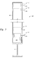
- FIG. 3 is an cutaway end view of a embodiment of a lift used in a preferred rig.
- a preferred embodiment of a rig made in accordance with the present invention may be used on a platform constructed to carry out hydrocarbon exploration and recovery operations either offshore or on land.
- the preferred rig facilitates the introduction of wirelines, a working string, a drill string, and other tubular umbilicals into a subterranean wellbore.
- the preferred rig also enables the efficient deployment and operation of bottom hole assemblies (BHAs).
- BHAs bottom hole assemblies
- Preferred rig 100 which is fixed (e.g., bolted) onto skids 14 , includes modules 200 , rails 300 and jacks 400 .
- modules 200 for clarity, not shown in FIG. 1 are the various equipment, facilities, and ancillary components typically found on well platforms. These items include generators, hydraulic pumps and hoses, electrical cables, data transmission wires, living quarters, storage facilities, and other equipment components and facilities that are known to those of ordinary skill in the art.
- module 200 is preferably a prefabricated standardized modular structure that can be preloaded with equipment.
- Module 200 has a rear frame 202 , a top frame 204 , a bottom frame 206 , an inner frame 208 , and side frames 210 .
- An exemplary dimension of module 200 may be thirty feet by thirty feet and ten feet in height.
- module 200 may be formed of nearly any required dimension, and utilize any number of acceptable frame structures. It is preferred that the framework ultimately used provides for storage areas suitable for housing well equipment.
- Co-pending application U.S. application, titled “CT Drilling Rig,” U.S. patent application Ser. No. 09/739,072, filed on Dec. 15, 2000 discloses embodiments of module designs and is incorporated by reference for all purposes.
- Inner frame 208 defines an open shaft that forms an open throat 102 for rig 100 (FIG. 1 ). Inner frame 208 also provides the foundation against which well equipment, such as powered arms, may be suspended. Such equipment is described in co-pending U.S. application Ser. No. 09/739,072, titled “CT Drilling Rig.”
- side frames 210 are each provided with lifting pads 214 .
- One lifting pad 214 is welded, or otherwise secured, to the bottom corners of each side frame 210 .
- Each lifting pad 214 includes a bore 216 for interlocking with jacks 400 (FIG. 1) in a manner described below. It will be understood that lifting pads 214 may be located in any position on module 200 .
- module 200 also includes a self-actuating latch 218 .
- Self-actuating latch 218 includes a female connector 220 disposed on the four out-board corners of top frame 204 and a male connector 222 disposed on the four out-board corners of bottom frame 206 . Because modules 200 may be stacked, self-actuating latch 218 is preferably ISO 9000 compliant and conforms to any other applicable standards that may govern latching mechanisms used to secure vertically stacked storage containers.
- One exemplary latch design may use a finger as the male connector and a complementary keyed slot as the female connector. The finger may incorporate a hooked end that engages a ledge or lip in the keyed slot. In any event, one of ordinary skill in the art will recognize that any number of latch designs may be suitable.
- modules 200 incorporates open internal spaces adapted to receive well equipment. While the type of equipment may vary depending on the nature of the well A construction or work-over operation at hand, an exemplary arrangement of well equipment for module 200 is as follows. Because one of ordinary skill in the art would be familiar with the equipment described, this equipment is not shown in the figures.
- a first module 230 may include a monitoring cabin. The monitoring cabin may houses alarms, control panels, communication systems, and other instrumentation needed to control well construction operations and production activities.
- a second module 240 may be fitted with equipment and tooling, such as accumulators, to support a blow-out preventer (BOP) stack.
- a third module 250 may be fitted with a hydraulic power pack to support well operations.
- a fourth module 260 may be fitted with mud pumps.
- a fifth module 270 may include the mud tanks that supply the drilling fluid. All of this equipment is pre-fitted into their respective modules 200 prior to shipment to offshore platform 10 . Thus, not only does module 200 act as a support structure for this equipment during well operations, module 200 acts as a storage container that facilitates the transportation and lifting and handling for well equipment.
- Rails 300 provide a guide for transporting modules 200 to rig 100 .
- Rails 300 are preferably I-beams that extend from a landing 302 into rig throat 102 .
- Rails 300 provide a support surface that enable other lifting and handling equipment, such as a trolley, to move module 200 .
- rails 300 may be modified to incorporate equipment such as pulleys, chains, rollers, or belts to independently move module 200 .
- jacks 400 cooperate to hoist/lower modules 200 during rig erection/disassembly operations.
- two jacks 400 are fixed to each skid 14 . Greater or fewer jacks 400 may be used depending on factors such as the weight and stability of modules 200 .
- Each jack includes a housing 402 , a lift 404 , and a retractable lock-rod 406 .
- Housing 402 protects jack 400 internals from damage arising from contact with surrounding equipment and also protects rig workers from injuries occurring from unintended contact with jack 400 .
- Hydraulic lift 404 may be a known piston-cylinder arrangement energized by pressurized hydraulic fluid.
- Hydraulic power is preferred to actuate lift 404 because hydraulic fluid is usually available on offshore facilities. If hydraulic fluid is not available, lift 404 may be adapted to use a different power source such as electricity. For example, an electric motor coupled to a worm gear may also be used as the lifting mechanism. Affixed to the end of lift 404 is retractable lock-rod 406 . Lock-rod 406 , when actuated, moves between an extended position, designated as “E,” and a retracted position, designated as “R.” Actuation may be accomplished by known hydraulic circuits or by known electro-mechanical means. In the extended position “E,” lock-rod 406 enters bore 216 of lifting pad 214 (FIG. 2 B).
- lifting pad 214 may be eliminated by using a retractable pallet (not shown) instead of lock-rod 406 .
- the retractable pallet would simply form a support surface on which module bottom frame 206 (FIG. 2A) would rest.
- lift 404 preferably elevates module 200 at least the height of module 200 plus some additional clearance distance. For example, for a module height of ten feet, lift 404 elevates module 200 (FIG. 1) about twelve feet. That is, lift 404 , in this example, has a stroke of about twelve feet.
- Lift 404 also has three static positions, designed as “A,” “B.” and “C.” Static position “A” represents the lowest pre-elevated position of lift 404 .
- Lift 404 shown in phantom, takes static position “C” at the full stroke distance.
- Lift 404 also shown in phantom, enters static position “B” when setting one module 200 onto another module 200 below.
- each of the modules 200 are fitted with a specific piece of equipment, e.g., mud tanks, mud pumps, hydraulic power packs, a BOP accumulators, and monitoring stations.
- Transport vehicles such as barges, transport each of these modules to the offshore facility.
- the cranes of the offshore facility in a succession of lifts, move each of modules 200 from the transport vehicle to, ultimately, the landing 302 of the rails 300 .
- a trolley moves the module 200 along the rails 300 and into the rig throat 102 .
- the lock-rods 406 when actuated, move to their extended position “E” and engage the module lifting pads 214 .
- the module 200 now secured in the jacks 400 is hoisted from position “A” to position “C.” With this module 200 suspended in position “C,” another module 200 is slid into the rig throat 102 . After verifying that the male and female latching mechanisms 218 of the two modules are aligned, the suspended module 200 is lowered from position “C” to position “B.” As the suspended module 200 reaches position “B,” the male and female latching mechanisms 218 engage.
- the lock-rods 406 return to their retracted position “R” and return to position “A.” Thereafter, the lock-rods 406 engage the lower module and lift both modules. When the lifts reach position “C,” the above steps are repeated for successive modules. Once all the modules are in place, the necessary connections are made up and additional equipment may be affixed onto the rig as needed.
- the preferred rig can be constructed without need of a specialized cranes and with minimal manual intervention. It can also be seen that equipment that would otherwise occupy the deck of the offshore platform is now stored within the preferred rig 100 itself. Thus, the relatively small “footprint” of the preferred rig 100 frees up valuable deck space for other offshore activities. Moreover, this small “footprint” enables the preferred rig 100 to be deployed in a greater number of offshore platforms. Also, it is contemplated that the preferred rig 100 may be fitted with sensors, video cameras, remote controls, and other systems than can enable a nearly automated erection of the rig 100 . Moreover, because of the modular nature of the rig 100 , the jacking mechanism and the pre-installation of the equipment into the modules, the preferred rig 100 can be contructed in a much shorter time than a prior art rig.
Landscapes
- Engineering & Computer Science (AREA)
- Life Sciences & Earth Sciences (AREA)
- Geology (AREA)
- Mining & Mineral Resources (AREA)
- Mechanical Engineering (AREA)
- Physics & Mathematics (AREA)
- Environmental & Geological Engineering (AREA)
- Fluid Mechanics (AREA)
- General Life Sciences & Earth Sciences (AREA)
- Geochemistry & Mineralogy (AREA)
- Earth Drilling (AREA)
- Placing Or Removing Of Piles Or Sheet Piles, Or Accessories Thereof (AREA)
Priority Applications (11)
| Application Number | Priority Date | Filing Date | Title |
|---|---|---|---|
| US10/020,367 US6675899B2 (en) | 2000-12-15 | 2001-12-12 | Self-erecting rig |
| BR0116054-0A BR0116054A (pt) | 2000-12-15 | 2001-12-13 | Aparelho de torre de perfuração, estrutura para perfurar um poço, e, método para montar uma estrutura de torre |
| PCT/US2001/049023 WO2002048500A2 (en) | 2000-12-15 | 2001-12-13 | Self-erecting rig |
| CNA018201601A CN1529786A (zh) | 2000-12-15 | 2001-12-13 | 自装配钻塔 |
| AU3102202A AU3102202A (en) | 2000-12-15 | 2001-12-13 | Self-erecting rig |
| AU2002231022A AU2002231022B9 (en) | 2000-12-15 | 2001-12-13 | Self-erecting rig |
| JP2002550198A JP2004530816A (ja) | 2000-12-15 | 2001-12-13 | 自己組立式掘削装置 |
| MXPA03003760A MXPA03003760A (es) | 2000-12-15 | 2001-12-13 | Avio auto-erectil. |
| CA002431877A CA2431877A1 (en) | 2000-12-15 | 2001-12-13 | Self-erecting rig |
| EP01991284A EP1341986A4 (de) | 2000-12-15 | 2001-12-13 | Sich selbst errichtender bohrturm |
| NO20032698A NO20032698L (no) | 2000-12-15 | 2003-06-13 | Selvreisende rigg |
Applications Claiming Priority (2)
| Application Number | Priority Date | Filing Date | Title |
|---|---|---|---|
| US25604900P | 2000-12-15 | 2000-12-15 | |
| US10/020,367 US6675899B2 (en) | 2000-12-15 | 2001-12-12 | Self-erecting rig |
Publications (2)
| Publication Number | Publication Date |
|---|---|
| US20020100619A1 US20020100619A1 (en) | 2002-08-01 |
| US6675899B2 true US6675899B2 (en) | 2004-01-13 |
Family
ID=26693356
Family Applications (1)
| Application Number | Title | Priority Date | Filing Date |
|---|---|---|---|
| US10/020,367 Expired - Fee Related US6675899B2 (en) | 2000-12-15 | 2001-12-12 | Self-erecting rig |
Country Status (10)
| Country | Link |
|---|---|
| US (1) | US6675899B2 (de) |
| EP (1) | EP1341986A4 (de) |
| JP (1) | JP2004530816A (de) |
| CN (1) | CN1529786A (de) |
| AU (2) | AU3102202A (de) |
| BR (1) | BR0116054A (de) |
| CA (1) | CA2431877A1 (de) |
| MX (1) | MXPA03003760A (de) |
| NO (1) | NO20032698L (de) |
| WO (1) | WO2002048500A2 (de) |
Cited By (4)
| Publication number | Priority date | Publication date | Assignee | Title |
|---|---|---|---|---|
| US20030221822A1 (en) * | 2002-06-04 | 2003-12-04 | Yarom Polsky | Jacking frame for coiled tubing operations |
| WO2004097161A1 (en) * | 2003-04-24 | 2004-11-11 | Helmerich & Payne, Inc. | Modular drilling rig substructure |
| US20060231273A1 (en) * | 2005-03-24 | 2006-10-19 | Armstrong James E | Apparatus for protecting wellheads and method of installing the same |
| US8793960B1 (en) * | 2009-09-25 | 2014-08-05 | DBRB Technologies, LLC | Method and support apparatus for supporting down hole rotary tools |
Families Citing this family (7)
| Publication number | Priority date | Publication date | Assignee | Title |
|---|---|---|---|---|
| NO328786B1 (no) * | 2005-07-15 | 2010-05-18 | Aker Engineering & Technology | Ubemannet vedlikehold av plattformer |
| US20090200856A1 (en) * | 2008-02-13 | 2009-08-13 | Chehade Elie J | Methods and systems for raising and lowering a rig mast and substructure by remote control |
| CN102561261B (zh) * | 2012-02-28 | 2014-01-08 | 中交二航局第三工程有限公司 | 采用简易门式起重机吊运预制面板建造码头的方法 |
| ES2554828T3 (es) * | 2012-09-19 | 2015-12-23 | Alstom Technology Ltd. | Conjunto y método de torre solar concentrada |
| CN112429666B (zh) * | 2020-10-16 | 2022-07-08 | 中国能源建设集团湖南火电建设有限公司 | 一种兆瓦级塔式光热发电集热器安装方法及安装系统装置 |
| CN113262027B (zh) * | 2021-06-08 | 2022-04-26 | 绍兴市中医院 | 一种用于骨水泥弥散的打孔枪 |
| CN114320172B (zh) * | 2021-11-23 | 2024-01-02 | 四川宏华石油设备有限公司 | 一种垂直起升钻机及安装方法 |
Citations (5)
| Publication number | Priority date | Publication date | Assignee | Title |
|---|---|---|---|---|
| US4821816A (en) * | 1986-04-25 | 1989-04-18 | W-N Apache Corporation | Method of assembling a modular drilling machine |
| US4899832A (en) | 1985-08-19 | 1990-02-13 | Bierscheid Jr Robert C | Modular well drilling apparatus and methods |
| US5248005A (en) * | 1991-02-13 | 1993-09-28 | Nabors Industries, Inc. | Self-propelled drilling module |
| US5407302A (en) | 1993-02-11 | 1995-04-18 | Santa Fe International Corp. | Method and apparatus for skid-off drilling |
| US5704427A (en) * | 1995-10-13 | 1998-01-06 | Buck; David A. | Portable well service rig |
Family Cites Families (6)
| Publication number | Priority date | Publication date | Assignee | Title |
|---|---|---|---|---|
| US4134237A (en) * | 1976-08-02 | 1979-01-16 | Pool Company | Modular section mast |
| US4885893A (en) * | 1987-09-10 | 1989-12-12 | Imi Engineering, Co. | Well mast structure |
| US5216867A (en) * | 1991-11-04 | 1993-06-08 | Sundowner Offshore Services, Inc. | Well mast structure |
| US5247776A (en) * | 1992-08-03 | 1993-09-28 | Halliburton Logging Services Inc. | Method for offshore rig up platform portable mast |
| US5423158A (en) * | 1993-04-02 | 1995-06-13 | Continental Emsco Company | Vertically erected mast |
| WO1997011243A1 (en) * | 1993-11-12 | 1997-03-27 | Dreco, Inc. | Telescoping derrick |
-
2001
- 2001-12-12 US US10/020,367 patent/US6675899B2/en not_active Expired - Fee Related
- 2001-12-13 WO PCT/US2001/049023 patent/WO2002048500A2/en not_active Ceased
- 2001-12-13 CA CA002431877A patent/CA2431877A1/en not_active Abandoned
- 2001-12-13 BR BR0116054-0A patent/BR0116054A/pt not_active IP Right Cessation
- 2001-12-13 CN CNA018201601A patent/CN1529786A/zh active Pending
- 2001-12-13 MX MXPA03003760A patent/MXPA03003760A/es unknown
- 2001-12-13 AU AU3102202A patent/AU3102202A/xx active Pending
- 2001-12-13 JP JP2002550198A patent/JP2004530816A/ja active Pending
- 2001-12-13 AU AU2002231022A patent/AU2002231022B9/en not_active Ceased
- 2001-12-13 EP EP01991284A patent/EP1341986A4/de not_active Withdrawn
-
2003
- 2003-06-13 NO NO20032698A patent/NO20032698L/no not_active Application Discontinuation
Patent Citations (5)
| Publication number | Priority date | Publication date | Assignee | Title |
|---|---|---|---|---|
| US4899832A (en) | 1985-08-19 | 1990-02-13 | Bierscheid Jr Robert C | Modular well drilling apparatus and methods |
| US4821816A (en) * | 1986-04-25 | 1989-04-18 | W-N Apache Corporation | Method of assembling a modular drilling machine |
| US5248005A (en) * | 1991-02-13 | 1993-09-28 | Nabors Industries, Inc. | Self-propelled drilling module |
| US5407302A (en) | 1993-02-11 | 1995-04-18 | Santa Fe International Corp. | Method and apparatus for skid-off drilling |
| US5704427A (en) * | 1995-10-13 | 1998-01-06 | Buck; David A. | Portable well service rig |
Non-Patent Citations (1)
| Title |
|---|
| PCT International Search Report for Application Serial No. PCT/US01/49023, dated Jun. 21, 2002 (pp. 4). |
Cited By (12)
| Publication number | Priority date | Publication date | Assignee | Title |
|---|---|---|---|---|
| US20030221822A1 (en) * | 2002-06-04 | 2003-12-04 | Yarom Polsky | Jacking frame for coiled tubing operations |
| US7073592B2 (en) * | 2002-06-04 | 2006-07-11 | Schlumberger Technology Corporation | Jacking frame for coiled tubing operations |
| WO2004097161A1 (en) * | 2003-04-24 | 2004-11-11 | Helmerich & Payne, Inc. | Modular drilling rig substructure |
| US20060231273A1 (en) * | 2005-03-24 | 2006-10-19 | Armstrong James E | Apparatus for protecting wellheads and method of installing the same |
| US7419006B2 (en) * | 2005-03-24 | 2008-09-02 | Wzi, Inc. | Apparatus for protecting wellheads and method of installing the same |
| US8793960B1 (en) * | 2009-09-25 | 2014-08-05 | DBRB Technologies, LLC | Method and support apparatus for supporting down hole rotary tools |
| US20140246188A1 (en) * | 2009-09-25 | 2014-09-04 | Douglas C. Burns | Support Apparatus for Supporting Down Hole Rotary Tools |
| US9650841B2 (en) * | 2009-09-25 | 2017-05-16 | Swivel Rental & Supply, L.L.C. | Support apparatus for supporting down hole rotary tools |
| US9938778B2 (en) * | 2009-09-25 | 2018-04-10 | Swivel Rental & Supply, L.L.C. | Support apparatus for supporting down hole rotary tools |
| US10301884B2 (en) * | 2009-09-25 | 2019-05-28 | Swivel Rental & Supply, L.L.C. | Support apparatus for supporting down hole rotary tools |
| US10633931B1 (en) * | 2009-09-25 | 2020-04-28 | Swivel Rental & Supply, L.L.C. | Support apparatus for supporting down hole rotary tools |
| US11661800B1 (en) * | 2009-09-25 | 2023-05-30 | Swivel Rental & Supply, L.L.C. | Support apparatus for supporting down hole rotary tools |
Also Published As
| Publication number | Publication date |
|---|---|
| NO20032698D0 (no) | 2003-06-13 |
| US20020100619A1 (en) | 2002-08-01 |
| EP1341986A4 (de) | 2005-04-20 |
| CA2431877A1 (en) | 2002-06-20 |
| EP1341986A2 (de) | 2003-09-10 |
| MXPA03003760A (es) | 2004-10-15 |
| BR0116054A (pt) | 2005-05-10 |
| AU3102202A (en) | 2002-06-24 |
| WO2002048500A2 (en) | 2002-06-20 |
| AU2002231022B9 (en) | 2005-04-07 |
| NO20032698L (no) | 2003-07-31 |
| AU2002231022B2 (en) | 2005-03-17 |
| JP2004530816A (ja) | 2004-10-07 |
| WO2002048500A3 (en) | 2002-10-17 |
| CN1529786A (zh) | 2004-09-15 |
Similar Documents
| Publication | Publication Date | Title |
|---|---|---|
| EP1756391B1 (de) | Begrenzte vor-ort-montage und begrenzte ausrüstungsunterstützung erforderndes modulares bohrsystem und einsatzverfahren | |
| EP2992160B1 (de) | Modulares bohrgestellsystem und verfahren zur montage davon | |
| CA2866346C (en) | Modular drilling rig system | |
| US6675899B2 (en) | Self-erecting rig | |
| EP3615762B1 (de) | Handhabung, prüfung, aufbewahrung einer steigrohranlegestranganordnung an bord eines schwimmenden schiffes | |
| US4666340A (en) | Offshore platform with removable modules | |
| WO1997013953A1 (en) | Portable well service rig | |
| AU2002231022A1 (en) | Self-erecting rig | |
| EA003481B1 (ru) | Подвижный, самоподъемный искусственный рабочий остров с модульным корпусом | |
| US20050241857A1 (en) | Method to transport and operate a small footprint tower to reduce environmental impact | |
| NL2006407C2 (en) | Method for removing a hydrocarbon production platform from sea. | |
| US20060231273A1 (en) | Apparatus for protecting wellheads and method of installing the same | |
| JP2004530816A5 (de) | ||
| US10513887B1 (en) | Self-elevating drilling unit drills petroleum well offshore with wellhead on seabed | |
| WO2018172529A1 (en) | Deck for offshore rig and method of forming same | |
| WO2008012482A1 (en) | Method and apparatus for erecting a mast | |
| MXPA99008027A (en) | Jack-up platform locking apparatus |
Legal Events
| Date | Code | Title | Description |
|---|---|---|---|
| AS | Assignment |
Owner name: HALLIBURTON ENERGY SERVICES, INC., TEXAS Free format text: ASSIGNMENT OF ASSIGNORS INTEREST;ASSIGNOR:COATS, E. ALAN;REEL/FRAME:012682/0470 Effective date: 20020128 |
|
| FEPP | Fee payment procedure |
Free format text: PAYOR NUMBER ASSIGNED (ORIGINAL EVENT CODE: ASPN); ENTITY STATUS OF PATENT OWNER: LARGE ENTITY |
|
| FEPP | Fee payment procedure |
Free format text: PAYOR NUMBER ASSIGNED (ORIGINAL EVENT CODE: ASPN); ENTITY STATUS OF PATENT OWNER: LARGE ENTITY Free format text: PAYER NUMBER DE-ASSIGNED (ORIGINAL EVENT CODE: RMPN); ENTITY STATUS OF PATENT OWNER: LARGE ENTITY |
|
| REMI | Maintenance fee reminder mailed | ||
| LAPS | Lapse for failure to pay maintenance fees | ||
| STCH | Information on status: patent discontinuation |
Free format text: PATENT EXPIRED DUE TO NONPAYMENT OF MAINTENANCE FEES UNDER 37 CFR 1.362 |
|
| FP | Lapsed due to failure to pay maintenance fee |
Effective date: 20080113 |