US6668995B2 - Variable inertia flywheel - Google Patents
Variable inertia flywheel Download PDFInfo
- Publication number
- US6668995B2 US6668995B2 US10/063,800 US6380002A US6668995B2 US 6668995 B2 US6668995 B2 US 6668995B2 US 6380002 A US6380002 A US 6380002A US 6668995 B2 US6668995 B2 US 6668995B2
- Authority
- US
- United States
- Prior art keywords
- mass
- primary
- assembly
- viscosity
- latcher
- Prior art date
- Legal status (The legal status is an assumption and is not a legal conclusion. Google has not performed a legal analysis and makes no representation as to the accuracy of the status listed.)
- Expired - Lifetime
Links
Images


Classifications
-
- F—MECHANICAL ENGINEERING; LIGHTING; HEATING; WEAPONS; BLASTING
- F16—ENGINEERING ELEMENTS AND UNITS; GENERAL MEASURES FOR PRODUCING AND MAINTAINING EFFECTIVE FUNCTIONING OF MACHINES OR INSTALLATIONS; THERMAL INSULATION IN GENERAL
- F16F—SPRINGS; SHOCK-ABSORBERS; MEANS FOR DAMPING VIBRATION
- F16F15/00—Suppression of vibrations in systems; Means or arrangements for avoiding or reducing out-of-balance forces, e.g. due to motion
- F16F15/10—Suppression of vibrations in rotating systems by making use of members moving with the system
- F16F15/12—Suppression of vibrations in rotating systems by making use of members moving with the system using elastic members or friction-damping members, e.g. between a rotating shaft and a gyratory mass mounted thereon
- F16F15/131—Suppression of vibrations in rotating systems by making use of members moving with the system using elastic members or friction-damping members, e.g. between a rotating shaft and a gyratory mass mounted thereon the rotating system comprising two or more gyratory masses
- F16F15/133—Suppression of vibrations in rotating systems by making use of members moving with the system using elastic members or friction-damping members, e.g. between a rotating shaft and a gyratory mass mounted thereon the rotating system comprising two or more gyratory masses using springs as elastic members, e.g. metallic springs
- F16F15/134—Wound springs
- F16F15/13407—Radially mounted springs
-
- F—MECHANICAL ENGINEERING; LIGHTING; HEATING; WEAPONS; BLASTING
- F16—ENGINEERING ELEMENTS AND UNITS; GENERAL MEASURES FOR PRODUCING AND MAINTAINING EFFECTIVE FUNCTIONING OF MACHINES OR INSTALLATIONS; THERMAL INSULATION IN GENERAL
- F16F—SPRINGS; SHOCK-ABSORBERS; MEANS FOR DAMPING VIBRATION
- F16F15/00—Suppression of vibrations in systems; Means or arrangements for avoiding or reducing out-of-balance forces, e.g. due to motion
- F16F15/10—Suppression of vibrations in rotating systems by making use of members moving with the system
- F16F15/12—Suppression of vibrations in rotating systems by making use of members moving with the system using elastic members or friction-damping members, e.g. between a rotating shaft and a gyratory mass mounted thereon
- F16F15/131—Suppression of vibrations in rotating systems by making use of members moving with the system using elastic members or friction-damping members, e.g. between a rotating shaft and a gyratory mass mounted thereon the rotating system comprising two or more gyratory masses
- F16F15/133—Suppression of vibrations in rotating systems by making use of members moving with the system using elastic members or friction-damping members, e.g. between a rotating shaft and a gyratory mass mounted thereon the rotating system comprising two or more gyratory masses using springs as elastic members, e.g. metallic springs
- F16F15/1338—Motion-limiting means, e.g. means for locking the spring unit in pre-defined positions
Definitions
- the present invention relates to flywheels employed in the drivetrain of vehicles, and more particularly to dual mass flywheels.
- flywheels connected to the engine and the clutch. While these types of flywheels generally improve the transmission NVH, they generally reduce the effectiveness of the flywheel in improving the NVH of the engine.
- a primary flywheel mass is connected directly to the engine crankshaft, while a secondary mass is connected to the primary mass via a spring and damper assembly.
- the primary flywheel mass has lower inertia than that of a conventional flywheel, and so is less effective in reducing transmission of the engine pulsations since the pulsations are reduced only by the inertia connected directly to the engine crankshaft.
- This increase in the engine NVH can lead to increased wear on the crankshaft or damage to accessories driven off of the front end accessory drive.
- those employing dual mass flywheels end up adding additional damper assemblies and friction plates to account for the engine NVH concerns.
- the present invention contemplates a flywheel and clutch assembly for transferring torque from an engine crankshaft to a transmission input shaft.
- the assembly includes a primary mass adapted to be rotationally fixed to the engine crankshaft, a clutch disc adapted to be rotationally fixed to the transmission input shaft, and a secondary mass rotationally engageable with the clutch disc for transferring torque thereto.
- a spring assembly is coupled between the primary mass and the secondary mass, and a latcher is connected between the primary mass and the secondary mass that is engageable to rotationally fix the primary mass to the secondary mass.
- variable inertia flywheel where a primary mass and a secondary mass can be coupled together via a spring or a spring and damper assembly under certain vehicle driving conditions, but can also be latched together to rotate as one mass under other vehicle driving conditions.
- An advantage of an embodiment of the present invention is that the flywheel and clutch assembly will adequately reduce the NVH for both the engine and the transmission.
- Another advantage of an embodiment of the present invention is that the vehicle will have improved vehicle launch characteristics.
- a further advantage of an embodiment of the present invention is that a mechanism employed to latch a primary and secondary mass together under certain driving conditions can also operate as a variable damper between the primary and secondary masses under other driving conditions.
- FIG. 1 is a schematic diagram of a vehicle drive train in accordance with a first embodiment of the present invention
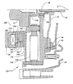
- FIG. 2 is a partial cross-sectional view of a flywheel and clutch assembly in accordance with the first embodiment of the present invention
- FIG. 3 is a view similar to FIG. 2, but illustrating a different portion of the assembly
- FIG. 4 is an elevation view of a portion of a radial spring and centrifugal latch assembly in accordance with the first embodiment of the present invention
- FIG. 5 is an elevation view of a primary mass of a flywheel in accordance with the first embodiment of the present invention.
- FIG. 6 is a schematic diagram similar to FIG. 1, but illustrating a second embodiment of the present invention.
- FIG. 7 is a partial cross-sectional view of a flywheel and clutch assembly in accordance with the second embodiment of the present invention.
- FIG. 8 is a schematic, elevation view of a portion of a variable damper/latch assembly in accordance with the second embodiment of the present invention.
- FIGS. 1-5 illustrate a flywheel and clutch assembly 20 in accordance with a first embodiment of the present invention.
- the assembly 20 is connected at a front end to a crankshaft 22 of an engine 24 , and at the other end to an input shaft 26 of a transmission 28 (or transaxle), and is generally enclosed in a clutch housing 29 .
- the crankshaft 22 typically also connects to and drives a front end accessory drive 30 .
- the output of the transmission 28 will drive the remainder of the vehicle driveline 32 , which can vary greatly depending upon whether the vehicle is front or rear wheel drive, among other factors, but is generally conventional and so will not be discussed further.
- a primary flywheel mass 34 is secured to the crankshaft 22 .
- This primary mass 34 is significantly smaller than what is conventionally used in a single mass flywheel assembly.
- the primary mass 34 includes a hub portion 36 , which is bolted to the crankshaft 22 , and an outer disc shaped portion 38 that is mounted to the hub portion 36 .
- the hub portion 36 is also mounted to the radially inner ends of a set of radial spring assemblies 40 via a first set of drive pins 42 .
- a second set of drive pins 44 mount the radially outer ends of the radial spring assemblies 40 to a secondary flywheel mass 46 .
- the radially inner portion of the secondary mass 46 mounts about the hub portion 36 via a bearing 48 . This bearing 48 allows for relative rotation between the hub portion 36 and the secondary mass 46 .
- the primary mass 34 preferably has a significantly smaller rotational inertia than the secondary mass 46 .
- the primary mass for example, may be on the order of ten to twenty percent of the rotational inertia of the secondary mass 46 . So the difference in inertia may be on the order of 0.1 Newton-meter-(seconds)-squared.
- the secondary mass 46 also includes a friction face 50 , which is shaped to engage with a face of a clutch disc assembly 52 .
- This clutch disc assembly 52 is mounted to the transmission input shaft 26 .
- the clutch disc assembly 52 also includes a face that can be selectively engaged with pressure plate 54 .
- a pressure plate cover assembly 58 and clutch applying spring 56 act to engage and disengage the clutch, and are actuated by a clutch release mechanism (not shown).
- the clutch release mechanism can be any of a number of configurations, and can be mechanically, electrically, and/or hydraulically controlled as are known to those skilled in the art, and so will not be discussed further.
- the secondary mass 46 also supports a pair of centrifugal latching mechanisms 60 , (one shown and the other located 180 degrees from the first).
- Each mechanism includes a latching pin 62 , which is mounted in a cavity formed by the secondary mass 46 , and is bolted to a radially oriented plunger 64 , which can slide in a channel formed by the secondary mass 46 .
- the radially outer end of the plunger 64 abuts a radially oriented spring 66 , which is also mounted in the channel and held in place by a spring cap and snap ring assembly 68 .
- the spring 66 is sized to press against the plunger 64 , thus biasing the latching pin 62 radially inward.
- This member 70 Bolted to, and forming a portion of the secondary mass is a ring shaped member 70 .
- This member 70 includes a pair of rotational stops 72 , which are located on its inner periphery adjacent to the latching mechanisms 60 , and a set of gear teeth 74 , which are located about its outer periphery and can be engaged with a starter motor (not shown) in order to start the vehicle engine 24 . Since the primary flywheel mass 34 is small (which has benefits as discussed herein), it would be difficult to locate the gear teeth 74 on the primary mass 34 where the teeth 74 could easily engage a starter motor.
- the gear teeth 74 on the secondary mass 46 can be engaged by a starter motor to drive the crankshaft 22 while starting the engine 24 , just as with a conventional single mass flywheel assembly.
- the rotational stops 72 on the ring shaped member 70 are located to engage rotational travel stops 76 on the primary mass 34 .
- There are four travel stops 76 which are located about the periphery of the primary mass 34 to limit the rotation of the secondary mass 34 relative to the primary mass 46 to about sixty degrees in either direction.
- FIG. 4 illustrates a radial spring 41 , shown in phantom, as it is oriented when the secondary mass 46 is rotated sixty degrees relative to the primary mass 34 .)
- These travel stops 76 protect the springs within the radial spring assemblies 40 from being damaged due to overtravel.
- the primary mass 34 includes a pair of latching slots 78 , each one aligned with a corresponding one of the latching pins 62 when the radial spring assemblies 40 are in their centered, i.e. zero degree, positions.
- FIG. 4 illustrates a radial spring 41 , shown with solid lines, as it is oriented with zero degrees of rotation between the secondary mass 46 and the primary mass 34 .
- the flywheel and clutch assembly 20 Under all engine operating conditions, the torque from the crankshaft 22 is passed directly to the primary mass 34 . If the engine RPMs are below a predetermined level, then the spring force from the radially oriented springs 66 will exceed the centrifugal force generated by the latching pins 62 and plungers 64 , forcing the latching pins 62 to slide radially inward into their respective latching slots 78 . The centrifugal latch mechanism 60 is now in its latched position, preventing the secondary mass 46 from rotating relative to the primary mass 34 .
- the centrifugal latch mechanism 60 When the centrifugal latch mechanism 60 is in its latched position, the torque is transferred directly from the primary mass 34 to the secondary mass 46 , without the radial spring assemblies 40 transferring any torque.
- the secondary mass 46 passes the torque to the clutch disc assembly 52 (assuming the clutch is engaged), which passes the torque directly to the transmission input shaft 26 . Since the secondary mass 46 is latched to and rotates with the primary mass, the two masses 34 , 46 act as if there were just one larger inertia mass connected to the crankshaft 22 . This larger effective inertia on the crankshaft 22 , then, helps to stabilize the engine 24 at idle and low RPM conditions.
- the centrifugal force generated by the latching pins 62 and plungers 64 will exceed the spring force from the radially oriented springs 66 . This will force the latching pins 62 to slide radially outward out of their respective latching slots 78 .
- the centrifugal latch mechanism 60 is now in its unlatched position, allowing the secondary mass 46 to rotate relative to the primary mass 34 .
- the torque is now transferred from the primary mass 34 to the secondary mass 46 via the radial spring assemblies 40 .
- the radial spring assemblies 40 isolate the primary mass 34 from the secondary mass 46 .
- the primary mass 34 is much smaller than is usually required due to the coupling of the secondary mass 46 at low RPMs, the engine rotating inertia is reduced, thus allowing for improved vehicle launch. Moreover, even though there is less mass to reduce the effects of the engine pulsations, they do not create as much of a problem at these higher engine RPMs. And, the larger secondary mass 46 is still rotationally fixed (assuming the clutch is engaged) to the transmission input shaft 26 , which stabilizes the transmission 28 , thus minimizing other NVH problems such as gear rattle and body boom.
- the spring on the latching mechanism 60 is preferably sized to allow the pin to slide out of the latching slots 78 at about 600 to 1000 RPMs, and more preferably at about 800 RPMs, although the particular rotational velocity selected for unlatching may vary depending upon various engine, driveline, and vehicle parameters.
- FIGS. 6-8 illustrate a flywheel and clutch assembly 120 in accordance with a second embodiment of the present invention.
- elements that are the same as the first will be designated with the same element numbers, but those that have changed or have been added will be designated with 100 series numbers.
- the engine 24 , FEAD 30 , crankshaft 22 , clutch disc assembly 52 , pressure plate 54 , transmission input shaft 26 , transmission 28 and remainder of the driveline 32 are the same as in the first embodiment.
- the flywheel and clutch assembly 120 has a primary flywheel mass 134 that is bolted to the crankshaft 22 .
- the radially inner end of the radial spring assemblies 140 are connected to the primary mass 134 via inner drive pins 142
- the radially outer ends of the spring assemblies 140 are connected to the secondary flywheel mass 146 via outer drive pins 144 .
- the radially inner portion of the secondary mass 146 is again mounted about the primary mass 134 via the bearing 48 .
- the secondary mass 146 again includes a friction face 50 , which is shaped to engage with the face of a clutch disc assembly 52 . This clutch disc assembly 52 is again mounted to the transmission input shaft 26 .
- a damper latching mechanism 160 couples between the primary mass 134 and the secondary mass 146 .
- the latching mechanism 160 not only serves to latch the secondary mass 146 to the primary mass 134 , but also can be electronically controlled to act as a torsional damper connected in parallel with the radial spring assemblies 140 .
- This latching mechanism 160 includes a vane disk 162 , which includes a pair of vane portions 163 .
- the vane disk 162 is splined to a generally ring shaped member 170 of the secondary mass 146 .
- the vane disk 162 is mounted adjacent to a fluid housing 182 , which is rotationally fixed to the primary mass 134 via a ring shaped, non-magnetic spacer 184 .
- the vane disk 162 , and the fluid housing 182 and spacer 184 define four fluid chambers 186 , and two channels 188 that each connect a respective two of the fluid chambers 186 .
- the fluid channels 188 are preferably about 0.6 millimeters wide and about 0.6 millimeters high.
- the fluid chambers 186 and channels 188 are filled with a magnetorheological (MR) fluid.
- MR magnetorheological
- a wire coil 190 and coil housing 192 are mounted to the engine 24 .
- a slotted cover 194 mounts to the coil housing 192 and is spaced apart from the primary mass 134 , spacer 184 and fluid housing 182 by an approximately 0.5 millimeter air gap.
- the engine 24 drives the crankshaft 22 , which in turn drives the primary mass 134 .
- This causes the housing 182 to rotate, which in turn causes the MR fluid to be pumped through the two channels 188 between the fluid cavities 186 .
- the channels 188 then, in effect act like fluid valves that control the flow of MR fluid between the fluid chambers 186 . It is the flowing of fluid through the channels 188 that allows for the rotation of the secondary mass 146 relative to the primary mass 134 —up to the point where the vanes 163 contact the fluid housing 182 , preventing further rotation in that direction.
- This flow of the viscous MR fluid through these channels 188 causes viscous damping to occur as the torque is transferred from the primary mass 134 to the secondary mass 146 .
- the radial spring assemblies 140 also transfer torque from the primary mass 134 to the secondary mass 146 in parallel with the latch assembly 160 . The torque is then transferred through the rest of the vehicle driveline in the same way as in the first embodiment.
- the magnetic field in the chambers 186 and the channels 188 is controlled by supplying electrical current to the coil 190 .
- the magnetic field is zero or very small and so the viscosity of the MR fluid is relatively low. This allows a relatively free flow of MR fluid through the channels 188 between the fluid chambers 186 , which, in turn, allows for some relative rotation between the primary mass 134 and the secondary mass 146 as the torque is transferred. A relatively small amount of damping occurs under this operating condition.
- the magnetic field is relatively high, causing the viscosity of the MR fluid to be very high such that it will not flow through the channels 188 .
- the primary mass 134 is effectively latched to the secondary mass 146 , and the two rotate together as one mass.
- the latch assembly 160 is configured to act as a latch when the coil 190 is supplied with about ten volts, and so below ten volts it will operate as a damper in parallel with the radial spring assembly.
- the latch assembly 160 may be configured to operate over a different range of voltages if so desired.
- the viscosity of the MR fluid is relatively high, but some of the MR fluid can still flow through the channels 188 , allowing for variable torsional damping between the primary mass 134 and the secondary mass 146 .
- the voltage supplied to the coil 190 and thus the strength of the resulting magnetic field, one can then selectively vary the viscosity of the MR fluid. Since the viscosity of the MR fluid is what determines the amount of damping, the variability of the MR fluid viscosity allows for variable damping. This variability allows for the amount of damping and the RPMs at which the latching assembly 160 latches to be controlled independent of or as a function of the engine RPMs, thus allowing for greater flexibility in controlling the NVH concerns for the engine and transmission.
Abstract
Description
Claims (12)
Priority Applications (1)
| Application Number | Priority Date | Filing Date | Title |
|---|---|---|---|
| US10/063,800 US6668995B2 (en) | 2002-05-14 | 2002-05-14 | Variable inertia flywheel |
Applications Claiming Priority (1)
| Application Number | Priority Date | Filing Date | Title |
|---|---|---|---|
| US10/063,800 US6668995B2 (en) | 2002-05-14 | 2002-05-14 | Variable inertia flywheel |
Publications (2)
| Publication Number | Publication Date |
|---|---|
| US20030213672A1 US20030213672A1 (en) | 2003-11-20 |
| US6668995B2 true US6668995B2 (en) | 2003-12-30 |
Family
ID=29418228
Family Applications (1)
| Application Number | Title | Priority Date | Filing Date |
|---|---|---|---|
| US10/063,800 Expired - Lifetime US6668995B2 (en) | 2002-05-14 | 2002-05-14 | Variable inertia flywheel |
Country Status (1)
| Country | Link |
|---|---|
| US (1) | US6668995B2 (en) |
Cited By (7)
| Publication number | Priority date | Publication date | Assignee | Title |
|---|---|---|---|---|
| US20050061601A1 (en) * | 2003-09-19 | 2005-03-24 | Stefina Brian K. | Variable torsional damper having magneto-rheological fluid damping in parallel with a spring damper |
| US20060102138A1 (en) * | 2004-11-08 | 2006-05-18 | Ford Global Technologies, Llc | Systems and methods for controlled shutdown and direct start for internal combustion engine |
| US20070080037A1 (en) * | 2005-10-07 | 2007-04-12 | Ford Global Technologies, Llc | Electromagnetic coupling device for engine accessories |
| US20070151918A1 (en) * | 2002-09-24 | 2007-07-05 | Daniel Fenioux | Vibration filter for a transmission with automatic, continuous or discontinuous, gearchange, especially for a motor vehicle |
| US20090320640A1 (en) * | 2008-06-30 | 2009-12-31 | Christopher Mark Elliott | Variable inertia flywheel |
| US20130270053A1 (en) * | 2012-04-13 | 2013-10-17 | Honda Motor Co., Ltd. | Power transmission device |
| US8701851B2 (en) | 2010-10-08 | 2014-04-22 | GM Global Technology Operations LLC | Selectable mass flywheel |
Families Citing this family (7)
| Publication number | Priority date | Publication date | Assignee | Title |
|---|---|---|---|---|
| EP2169214B1 (en) | 2008-09-24 | 2019-04-03 | Volvo Car Corporation | Flywheel arrangement for an internal combustion engine |
| US8726762B2 (en) | 2010-06-28 | 2014-05-20 | Honeywell International Inc. | Tunable mass damper for use with a reaction wheel assembly |
| DE102011114961B4 (en) | 2010-10-08 | 2019-10-02 | GM Global Technology Operations LLC (n. d. Ges. d. Staates Delaware) | Flywheel with selectable mass for a drive train of a motor vehicle |
| US20120234131A1 (en) * | 2011-03-16 | 2012-09-20 | GM Global Technology Operations LLC | Dual-mass flywheel lock-out clutch |
| DE112016000599A5 (en) * | 2015-02-04 | 2017-12-21 | Schaeffler Technologies AG & Co. KG | Clutch unit, use of a CSC actuating cylinder and method for operating a clutch unit |
| DE102016202109A1 (en) * | 2016-02-12 | 2016-12-22 | Schaeffler Technologies AG & Co. KG | reciprocating engine |
| CN109387360B (en) * | 2018-12-05 | 2023-12-26 | 西南交通大学 | Variable inertia flywheel system of fixed test bed |
Citations (17)
| Publication number | Priority date | Publication date | Assignee | Title |
|---|---|---|---|---|
| US4624351A (en) * | 1983-12-16 | 1986-11-25 | Sachs-Systemtechnik Gmbh | Friction disc clutch for a motor vehicle |
| US4638684A (en) * | 1983-10-24 | 1987-01-27 | Luk Lamellen Und Kupplungsbau Gmbh | Assembly for taking up and compensating for torque-induced shocks |
| US4813295A (en) * | 1985-02-19 | 1989-03-21 | Fichtel & Sachs Ag | Fly-wheel unit with disengageable friction device |
| US4856636A (en) * | 1987-02-07 | 1989-08-15 | Luk Lamellen Und Kupplungsbau Gmbh | Apparatus for damping fluctuations of torque |
| US5007303A (en) * | 1988-04-13 | 1991-04-16 | Nissan Motor Co., Ltd. | Variable inertial mass flywheel |
| US5245889A (en) * | 1991-04-08 | 1993-09-21 | Atsugi Unisia Corp. | Flywheel |
| WO1994027062A1 (en) * | 1993-05-19 | 1994-11-24 | Scania Cv Aktiebolag | Dual mass flywheel |
| US5678460A (en) * | 1994-06-06 | 1997-10-21 | Stahl International, Inc. | Active torsional vibration damper |
| US5711191A (en) * | 1991-04-14 | 1998-01-27 | Valeo | Damping flywheel notably for a motor vehicle |
| US5720475A (en) * | 1994-01-26 | 1998-02-24 | Valeo | Torsion damping device, especially for a motor vehicle |
| US5762557A (en) * | 1993-12-23 | 1998-06-09 | Valeo | Damped flywheel having a resilient member disposed between two coaxial masses |
| US5816924A (en) * | 1996-07-10 | 1998-10-06 | Exedy Corporation | Flywheel assembly |
| US5823880A (en) * | 1996-07-10 | 1998-10-20 | Exedy Corporation | Dual flywheel assembly with lockup mechanism between two flywheels |
| DE29921011U1 (en) * | 1999-03-10 | 2000-03-02 | Opel Adam Ag | Dual mass flywheel |
| US6050380A (en) * | 1997-05-09 | 2000-04-18 | Mannesmann Sachs Ag | Friction clutch with a compensating system |
| US6287205B1 (en) * | 1998-10-07 | 2001-09-11 | Valeo | Dual mass damping flywheel, in particular for motor vehicle |
| FR2815686A1 (en) * | 2000-10-25 | 2002-04-26 | Mannesmann Sachs Ag | Torsion damper comprises flywheel and ring gear around it with control weights biased inwards by spring to engage with recess in flywheel, centrifugal force overcoming force of spring when speed of rotation exceeds predetermined value |
-
2002
- 2002-05-14 US US10/063,800 patent/US6668995B2/en not_active Expired - Lifetime
Patent Citations (17)
| Publication number | Priority date | Publication date | Assignee | Title |
|---|---|---|---|---|
| US4638684A (en) * | 1983-10-24 | 1987-01-27 | Luk Lamellen Und Kupplungsbau Gmbh | Assembly for taking up and compensating for torque-induced shocks |
| US4624351A (en) * | 1983-12-16 | 1986-11-25 | Sachs-Systemtechnik Gmbh | Friction disc clutch for a motor vehicle |
| US4813295A (en) * | 1985-02-19 | 1989-03-21 | Fichtel & Sachs Ag | Fly-wheel unit with disengageable friction device |
| US4856636A (en) * | 1987-02-07 | 1989-08-15 | Luk Lamellen Und Kupplungsbau Gmbh | Apparatus for damping fluctuations of torque |
| US5007303A (en) * | 1988-04-13 | 1991-04-16 | Nissan Motor Co., Ltd. | Variable inertial mass flywheel |
| US5245889A (en) * | 1991-04-08 | 1993-09-21 | Atsugi Unisia Corp. | Flywheel |
| US5711191A (en) * | 1991-04-14 | 1998-01-27 | Valeo | Damping flywheel notably for a motor vehicle |
| WO1994027062A1 (en) * | 1993-05-19 | 1994-11-24 | Scania Cv Aktiebolag | Dual mass flywheel |
| US5762557A (en) * | 1993-12-23 | 1998-06-09 | Valeo | Damped flywheel having a resilient member disposed between two coaxial masses |
| US5720475A (en) * | 1994-01-26 | 1998-02-24 | Valeo | Torsion damping device, especially for a motor vehicle |
| US5678460A (en) * | 1994-06-06 | 1997-10-21 | Stahl International, Inc. | Active torsional vibration damper |
| US5816924A (en) * | 1996-07-10 | 1998-10-06 | Exedy Corporation | Flywheel assembly |
| US5823880A (en) * | 1996-07-10 | 1998-10-20 | Exedy Corporation | Dual flywheel assembly with lockup mechanism between two flywheels |
| US6050380A (en) * | 1997-05-09 | 2000-04-18 | Mannesmann Sachs Ag | Friction clutch with a compensating system |
| US6287205B1 (en) * | 1998-10-07 | 2001-09-11 | Valeo | Dual mass damping flywheel, in particular for motor vehicle |
| DE29921011U1 (en) * | 1999-03-10 | 2000-03-02 | Opel Adam Ag | Dual mass flywheel |
| FR2815686A1 (en) * | 2000-10-25 | 2002-04-26 | Mannesmann Sachs Ag | Torsion damper comprises flywheel and ring gear around it with control weights biased inwards by spring to engage with recess in flywheel, centrifugal force overcoming force of spring when speed of rotation exceeds predetermined value |
Non-Patent Citations (1)
| Title |
|---|
| Schulte, L. F., Dual Mass Flywheels, Feb. 1986. |
Cited By (14)
| Publication number | Priority date | Publication date | Assignee | Title |
|---|---|---|---|---|
| US20070151918A1 (en) * | 2002-09-24 | 2007-07-05 | Daniel Fenioux | Vibration filter for a transmission with automatic, continuous or discontinuous, gearchange, especially for a motor vehicle |
| US7500416B2 (en) * | 2002-09-24 | 2009-03-10 | Valeo Embrayages | Vibration filter for a transmission with automatic, continuous or discontinuous, gearchange, especially for a motor vehicle |
| US6883655B2 (en) * | 2003-09-19 | 2005-04-26 | Borgwarner, Inc. | Variable torsional damper having magneto-rheological fluid damping in parallel with a spring damper |
| US20050061601A1 (en) * | 2003-09-19 | 2005-03-24 | Stefina Brian K. | Variable torsional damper having magneto-rheological fluid damping in parallel with a spring damper |
| US20100083927A1 (en) * | 2004-11-08 | 2010-04-08 | Ford Global Technologies Llc | Systems and methods for controlled shutdown and direct start for internal combustion engine |
| US7654238B2 (en) * | 2004-11-08 | 2010-02-02 | Ford Global Technologies, Llc | Systems and methods for controlled shutdown and direct start for internal combustion engine |
| US20060102138A1 (en) * | 2004-11-08 | 2006-05-18 | Ford Global Technologies, Llc | Systems and methods for controlled shutdown and direct start for internal combustion engine |
| US7856954B2 (en) | 2004-11-08 | 2010-12-28 | Ford Global Technologies, Llc | Systems and methods for controlled shutdown and direct start for internal combustion engine |
| US7467697B2 (en) | 2005-10-07 | 2008-12-23 | Ford Global Technologies, Llc | Electromagnetic coupling device for engine accessories |
| US20070080037A1 (en) * | 2005-10-07 | 2007-04-12 | Ford Global Technologies, Llc | Electromagnetic coupling device for engine accessories |
| US20090320640A1 (en) * | 2008-06-30 | 2009-12-31 | Christopher Mark Elliott | Variable inertia flywheel |
| US8701851B2 (en) | 2010-10-08 | 2014-04-22 | GM Global Technology Operations LLC | Selectable mass flywheel |
| US20130270053A1 (en) * | 2012-04-13 | 2013-10-17 | Honda Motor Co., Ltd. | Power transmission device |
| US9091306B2 (en) * | 2012-04-13 | 2015-07-28 | Honda Motor Co., Ltd. | Power transmission device |
Also Published As
| Publication number | Publication date |
|---|---|
| US20030213672A1 (en) | 2003-11-20 |
Similar Documents
| Publication | Publication Date | Title |
|---|---|---|
| US6668995B2 (en) | Variable inertia flywheel | |
| US8028602B2 (en) | Active vibrational damper | |
| US6976920B2 (en) | Torque fluctuation absorbing apparatus having structure for reducing misalignment of torque limiter during assembling thereof, and method for assembling the same | |
| US7431138B2 (en) | Start-up clutch assembly | |
| US7591357B2 (en) | Crankshaft torque modulator | |
| JP4450574B2 (en) | Torsional vibration damper | |
| US4254855A (en) | Coaxial spring damper drive | |
| US3485063A (en) | Torsional isolator coupling | |
| US7717792B2 (en) | Torsional detuner | |
| KR20020023137A (en) | Starting clutch | |
| US20210215225A1 (en) | Torsion damper for vehicle | |
| US5433666A (en) | Torsion damping device with a dynamic vibration damper, in particular for automotive vehicles | |
| JPH02278019A (en) | Elastic coupling | |
| KR101055839B1 (en) | Torque converter of car | |
| EP0566992B1 (en) | Improved spiral spring shape | |
| US20050183923A1 (en) | Electromagnetic clutch | |
| US5226514A (en) | Mounting for rotating spiral spring | |
| EP1507097B1 (en) | Clutch driven disk with predamper | |
| KR20070108670A (en) | Dynamic damper of drive shaft | |
| KR100561938B1 (en) | Disk & Hub Assembly for Electronic Clutch_ | |
| US20200240474A1 (en) | Polygonal Spring Coupling | |
| CN108317216B (en) | Torsional damper and clutch and vehicle using same | |
| JP2003507667A (en) | Torsional vibration damper | |
| GB2340579A (en) | Torsional vibration damper | |
| GB2383626A (en) | Torsional vibration damper |
Legal Events
| Date | Code | Title | Description |
|---|---|---|---|
| AS | Assignment |
Owner name: FORD MOTOR COMPANY, MICHIGAN Free format text: ASSIGNMENT OF ASSIGNORS INTEREST;ASSIGNORS:JANSON, DAVID ALLEN;GOLESKI, GREGORY DANIEL;GINDER, JOHN MATTHEW;AND OTHERS;REEL/FRAME:012690/0461 Effective date: 20020409 Owner name: FORD GLOBAL TECHNOLOGIES, INC., MICHIGAN Free format text: ASSIGNMENT OF ASSIGNORS INTEREST;ASSIGNOR:FORD MOTOR COMPANY;REEL/FRAME:012690/0464 Effective date: 20020514 |
|
| AS | Assignment |
Owner name: FORD GLOBAL TECHNOLOGIES, LLC, MICHIGAN Free format text: MERGER;ASSIGNOR:FORD GLOBAL TECHNOLOGIES, INC.;REEL/FRAME:013987/0838 Effective date: 20030301 Owner name: FORD GLOBAL TECHNOLOGIES, LLC,MICHIGAN Free format text: MERGER;ASSIGNOR:FORD GLOBAL TECHNOLOGIES, INC.;REEL/FRAME:013987/0838 Effective date: 20030301 |
|
| STCF | Information on status: patent grant |
Free format text: PATENTED CASE |
|
| FPAY | Fee payment |
Year of fee payment: 4 |
|
| FPAY | Fee payment |
Year of fee payment: 8 |
|
| FPAY | Fee payment |
Year of fee payment: 12 |