EP1507097B1 - Clutch driven disk with predamper - Google Patents
Clutch driven disk with predamper Download PDFInfo
- Publication number
- EP1507097B1 EP1507097B1 EP04018224A EP04018224A EP1507097B1 EP 1507097 B1 EP1507097 B1 EP 1507097B1 EP 04018224 A EP04018224 A EP 04018224A EP 04018224 A EP04018224 A EP 04018224A EP 1507097 B1 EP1507097 B1 EP 1507097B1
- Authority
- EP
- European Patent Office
- Prior art keywords
- predamper
- driven
- plate
- disk
- cover plate
- Prior art date
- Legal status (The legal status is an assumption and is not a legal conclusion. Google has not performed a legal analysis and makes no representation as to the accuracy of the status listed.)
- Expired - Fee Related
Links
Images


Classifications
-
- F—MECHANICAL ENGINEERING; LIGHTING; HEATING; WEAPONS; BLASTING
- F16—ENGINEERING ELEMENTS AND UNITS; GENERAL MEASURES FOR PRODUCING AND MAINTAINING EFFECTIVE FUNCTIONING OF MACHINES OR INSTALLATIONS; THERMAL INSULATION IN GENERAL
- F16F—SPRINGS; SHOCK-ABSORBERS; MEANS FOR DAMPING VIBRATION
- F16F15/00—Suppression of vibrations in systems; Means or arrangements for avoiding or reducing out-of-balance forces, e.g. due to motion
- F16F15/10—Suppression of vibrations in rotating systems by making use of members moving with the system
- F16F15/12—Suppression of vibrations in rotating systems by making use of members moving with the system using elastic members or friction-damping members, e.g. between a rotating shaft and a gyratory mass mounted thereon
- F16F15/121—Suppression of vibrations in rotating systems by making use of members moving with the system using elastic members or friction-damping members, e.g. between a rotating shaft and a gyratory mass mounted thereon using springs as elastic members, e.g. metallic springs
- F16F15/123—Wound springs
- F16F15/1238—Wound springs with pre-damper, i.e. additional set of springs between flange of main damper and hub
Definitions
- This invention relates in general to friction clutches and in particular to predampers for clutch driven disks.
- Clutches are well known devices used to selectively connect a source of rotational power to a driven mechanism.
- a clutch is used to drivingly connect an engine to a transmission.
- vibrations are transmitted through the clutch and into the transmission and other drive-train components, producing undesirable operating conditions, such as gear rattle.
- Clutches generally include a clutch hub engaged for rotation with a transmission input shaft and a clutch disk selectively engaged for rotation with the engine flywheel.
- clutches typically employ a plurality of compression damping springs between the clutch hub and the clutch disc. These springs are typically disposed in spring pockets circumferentially located around the clutch hub. Compression of the damping springs is limited by stops disposed between the hub and the clutch disk, limiting relative rotation therebetween.
- the damping springs provide some degree of isolation between the engine and transmission to reduce the transmission of vibration due to engine firing pulses and other engine speed fluctuations. However, vibrations can still be transmitted through the damping springs to produce gear rattle.
- One solution to further reducing the transmission of vibrations has been to split the hub into an inner hub directly connected to the transmission input shaft and an outer hub connected to the clutch disc through the damping springs.
- the inner hub and outer hub are configured to provide a predetermined amount of rotative lash between the two parts.
- a predamper is placed between the inner hub and the outer hub.
- the predamper has springs of particular rates and preload characteristics selected to further damp out vibrations that can induce gear rattle.
- One known predamper configuration includes driving and driven elements; wherein the driven element is rotatably fixed to the inner hub and the driving element is rotatably fixed to the outer hub with a plurality of compression predamper springs disposed therebetween.
- the predamper springs are generally much smaller than, and of a much lower spring rate than, the damping springs disposed between the outer hub and the clutch disc and typically require end caps that facilitate the retention of predamper springs within the predamper. While this design has proven functionally successful, the additional components undesirably increase the axial length of the clutch package and inhibit the ability to incorporate a hysteresis component into the predamper for further torsional damping.
- a f urther known predamper configuration of this basic design is known from DE 40 40 593 A comprising two driving elements affixed to the outer hub and a driven element rotatably fixed to the inner hub and sandwiched between the two driving elements.
- US-A 6,050,382 discloses a clutch disk for a motor vehicle friction clutch having a load torsion oscillation damper and an idling torsion oscillation damper with a friction device and comprising the features of the preamble of claim 1. Due to the idling torsion oscillation damper springs (i.e.
- the invention comprises the features of claim 1.
- a driven disk includes a rotatable disk assembly including a disk plate.
- the driven disk also includes a hub assembly having an inner hub and an outer hub rotatable relative to the inner hub and secured to at least one cover plate.
- the hub assembly is rotatable relative to the disk assembly.
- the driven disk also includes a predamper having a driving element and a driven element.
- the driving element includes the cover plate and the driven element includes a predamper driven plate fixed to the inner hub.
- the cover plate includes a number of apertures and the predamper driven plate includes a number of sockets at least partially aligned with the apertures in the cover plate.
- An energy storage member is disposed within the sockets in the cover plate and the predamper driven plate.
- the energy storage member absorbs torque as a function of relative rotation between the inner hub and the outer hub.
- the predamper of the present invention reduces the axial width of the driven disk, particularly when compared to the prior art, and allows the optional incorporation of a hysteresis component into the predamper if desired.
- FIG. 1 is a front view of a driven disk according to an embodiment of the present invention
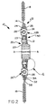
- FIG. 2 is a cross-sectional view of the driven disk of FIG. 1 taken along section 2-2, revealing the operative elements of the present invention
- FIG. 3 is an exploded view of a hub assembly according to an embodiment of the invention.
- FIG. 4 is a detailed cross-sectional view of the driven disk shown in FIG. 2 .
- Driven disk 10 includes a rotatable disk assembly 12 having a disk plate 14 that includes a plurality of apertures 16.
- a number of friction pads 18 are attached to disk plate 14 for frictional engagement between a clutch pressure plate and a driving member, such as an engine flywheel.
- a hub assembly 20 includes an inner hub 22 having spines for slidable engagement with a transmission input shaft (not shown), and an outer hub 23 secured to a pair of spring cover plates 24 and 25.
- First and second spring cover plates 24, 25 are fixedly attached to outer hub 23 by a plurality of fasteners 21, such as rivets.
- Spring cover plates 24, 25 each include a plurality of sockets 26 disposed therein, which are at least partially aligned with apertures 16 in disk plate 14. Sockets 26 may include or may be at least partially defined by an aperture as shown the illustrated embodiment.
- An energy storage member 28 is disposed within each of the correspondingly aligned apertures 16 and sockets 26 within disk plate 14 and each spring cover plate 24, 25, respectively.
- disk assembly 12 is rotatable relative to hub assembly 20.
- Inner hub 22, along with driven disk 10, has an axis of rotation (A-A) and external teeth 29 defming axially extending gaps therebetween (see, e.g., FIG. 3 ).
- Outer hub 23 is disposed over inner hub 22 and has internal teeth 30 disposed in the axially extending gaps between external teeth 29 of inner hub 22.
- the internal teeth 30 of outer hub 23 are smaller than the axially extending gaps, enabling a predetermined amount of relative rotation between inner hub 22 and outer hub 23.
- At least one reinforcing plate 31, as shown in FIG. 2 is disposed between disk plate 14 and spring cover plate 25.
- driven disk 10 includes a disk plate 14 fixedly attached to a first reinforcing plate 31A and a second reinforcing plate 31B by a plurality of rivets 32 positioned radially outward of first and second spring cover plates 24 and 25.
- Reinforcing plates 31A and 31B include a plurality of apertures 34 and 36, respectively, at least partially aligned with apertures 16 in disk plate 14.
- driven disk 10 may further include at least one lateral plate 40.
- a lateral plate is disposed adjacent each of first and second spring cover plates 24, 25 (see, e.g., FIG. 4 ).
- the optional lateral plates 40 are also fixedly attached to outer hub 23 by fasteners 21 and include a plurality of apertures 42 at least partially aligned with apertures 16 in disk plate 14.
- Driven disk 10 also includes a predamper 50 having a predamper driving element and a predamper driven element.
- predamper 50 includes a predamper driven plate 52, which functions as the predamper driven element, and a plurality of energy storage members 54.
- Second spring cover plate 25 includes a plurality of apertures 56 sized to receive energy storage members 54. When so configured, second cover plate 25 functions as the predamper driving element, eliminating the need for a separate predamper driving plate as required in the prior art.
- Predamper driven plate 52 is rotatably connected to the predamper driving element (i.e., second spring cover plate 25) by second energy storage members 54.
- the annular predamper driven plate 52 is rotatably fixed to inner hub 22.
- predamper driven plate 52 includes a number of inwardly radially extending internal teeth received in corresponding axially extending gaps on inner hub 22, preventing rotation of predamper driven plate 52 relative to inner hub 22.
- Predamper driven plate 52 also includes a planar base portion 60 disposed against second spring cover plate 25.
- a series of sockets 62 are disposed through planar base portion 60 in near radial and circumferential alignment with apertures 56 on second spring cover plate 25 to accommodate energy storage members 54. Sockets 62 may include or may be at least partially defined by an aperture as shown in FIG. 4 .
- a series of holes 64 are dispose through planar base portion 60 radially inward of sockets 62 (see, e.g., FIG. 1 ); however, a single annular aperture is also possible in place of holes 64.
- the second series of holes 64, or annular aperture if so configured, are sized to accommodate fasteners 21, particularly movement of fasteners 21 relative to predamper driven plate 52.
- a snap ring 66 which is secured in a groove in inner hub 22, axially retains predamper driven plate 52 on inner hub 22.
- First energy storage members 28 are disposed within sockets 26 and apertures 16, 34, 36, 42 for absorbing torque as a function of relative rotation between hub assembly 20 and disk assembly 12.
- a section of second spring cover plate 25 has been removed to reveal energy storage members 28 as a plurality of coil springs, specifically a plurality of outer coil springs 70 and inner coil springs 72.
- Outer coil springs 70 are operatively disposed between the disk assembly 12 and the hub assembly 20. More specifically, outer coil springs 70 contact disk plate 14 and reinforcing plates 31A, 31B at a first end and first spring cover plate 24 and second spring cover plate 25 at a second end.
- driven disk 10 of the present invention damps torsional vibrations in a driveline as a result of the relative rotation between disk assembly 12 and hub assembly 20. More specifically, as a torsional vibration is introduced to driven disk 10, hub assembly 20 rotates with respect to disk assembly 12, whereby torque spikes are dissipated in the form of heat resulting from friction as the coil springs 70, 72 are compressed and then expand back to their initial state.
- energy storage members 54 are disposed within apertures 56 and sockets 62 for absorbing torque as a function of relative rotation between outer hub 23 and inner hub 22.
- energy storage members are coil springs that are generally smaller than, and of lower spring rate than, coil springs 70, 72.
- the predamper driving element i.e., second spring cover plate 25
- outer hub 23 may rotate relative to predamper driven plate 52 and inner hub 22, whereby torque spikes are dissipated in the form of heat resulting from friction as the coil springs (energy storage members 54) are compressed and then expand back to their initial state.
- Torsional damping is achieved within the present invention by providing an energy storage component (i.e., energy storage members 28, 54).
- an optional hysteresis component may also be including in driven disk 10 to provide supplemental torsional damping.
- an optional hysteresis, or frictional component 80 is provided between predamper driven plate 52 and the predamper driving element (i.e., second spring cover plate 25).
- the hysteresis component 80 may be a friction pack or other device that increases the surface-to-surface coefficient of friction between the predamper driven plate 52 and second spring cover plate 25.
- a portion of predamper driven plate 52 may be axially offset relative to planar base portion 60 to accommodate hysteresis component 80. As the load along the axis of rotation A-A increases between the hub assembly 20 and the disk assembly 12, the resulting friction force is increased.
Description
- This invention relates in general to friction clutches and in particular to predampers for clutch driven disks.
- Clutches are well known devices used to selectively connect a source of rotational power to a driven mechanism. For instance, in a vehicle drive-train system, a clutch is used to drivingly connect an engine to a transmission. When the engine is drivingly connected with the transmission by the clutch, vibrations are transmitted through the clutch and into the transmission and other drive-train components, producing undesirable operating conditions, such as gear rattle.
- Clutches generally include a clutch hub engaged for rotation with a transmission input shaft and a clutch disk selectively engaged for rotation with the engine flywheel. To reduce the transmission of vibrations, clutches typically employ a plurality of compression damping springs between the clutch hub and the clutch disc. These springs are typically disposed in spring pockets circumferentially located around the clutch hub. Compression of the damping springs is limited by stops disposed between the hub and the clutch disk, limiting relative rotation therebetween. The damping springs provide some degree of isolation between the engine and transmission to reduce the transmission of vibration due to engine firing pulses and other engine speed fluctuations. However, vibrations can still be transmitted through the damping springs to produce gear rattle.
- One solution to further reducing the transmission of vibrations has been to split the hub into an inner hub directly connected to the transmission input shaft and an outer hub connected to the clutch disc through the damping springs. The inner hub and outer hub are configured to provide a predetermined amount of rotative lash between the two parts. A predamper is placed between the inner hub and the outer hub. The predamper has springs of particular rates and preload characteristics selected to further damp out vibrations that can induce gear rattle.
- One known predamper configuration includes driving and driven elements; wherein the driven element is rotatably fixed to the inner hub and the driving element is rotatably fixed to the outer hub with a plurality of compression predamper springs disposed therebetween. The predamper springs are generally much smaller than, and of a much lower spring rate than, the damping springs disposed between the outer hub and the clutch disc and typically require end caps that facilitate the retention of predamper springs within the predamper. While this design has proven functionally successful, the additional components undesirably increase the axial length of the clutch package and inhibit the ability to incorporate a hysteresis component into the predamper for further torsional damping. A further known predamper configuration of this basic design is known from
DE 40 40 593 AUS-A 6,050,382 discloses a clutch disk for a motor vehicle friction clutch having a load torsion oscillation damper and an idling torsion oscillation damper with a friction device and comprising the features of the preamble of claim 1. Due to the idling torsion oscillation damper springs (i.e. the predamper springs) being arranged laterally of and in an axial distance from an adjacent cover plate the idling torsion vibration damper tends to increase the axial width of the assembly.
To improve the before explained predamper configurations the invention comprises the features of claim 1. - A driven disk is disclosed that includes a rotatable disk assembly including a disk plate. The driven disk also includes a hub assembly having an inner hub and an outer hub rotatable relative to the inner hub and secured to at least one cover plate. The hub assembly is rotatable relative to the disk assembly. The driven disk also includes a predamper having a driving element and a driven element. The driving element includes the cover plate and the driven element includes a predamper driven plate fixed to the inner hub. The cover plate includes a number of apertures and the predamper driven plate includes a number of sockets at least partially aligned with the apertures in the cover plate. An energy storage member is disposed within the sockets in the cover plate and the predamper driven plate. The energy storage member absorbs torque as a function of relative rotation between the inner hub and the outer hub. Among other things, the predamper of the present invention reduces the axial width of the driven disk, particularly when compared to the prior art, and allows the optional incorporation of a hysteresis component into the predamper if desired.
- Embodiments of the invention will now be described, by way of example, with reference to the accompanying drawings, wherein:
-
FIG. 1 is a front view of a driven disk according to an embodiment of the present invention; -
FIG. 2 is a cross-sectional view of the driven disk ofFIG. 1 taken along section 2-2, revealing the operative elements of the present invention; -
FIG. 3 is an exploded view of a hub assembly according to an embodiment of the invention; and -
FIG. 4 is a detailed cross-sectional view of the driven disk shown inFIG. 2 . - Referring now to the drawings, the preferred illustrative embodiments of the present invention are shown in detail. Although the drawings represent some preferred embodiments of the present invention, the drawings are not necessarily to scale and certain features may be exaggerated to better illustrate and explain the present invention. Further, the embodiments set forth herein are not intended to be exhaustive or otherwise limit or restrict the invention to the precise forms and configurations shown in the drawings and disclosed in the following detailed description.
- Referring now to
FIGS. 1 and2 , a drivendisk 10 according to an embodiment of the present invention is shown.Driven disk 10 includes a rotatable disk assembly 12 having adisk plate 14 that includes a plurality of apertures 16. A number offriction pads 18 are attached todisk plate 14 for frictional engagement between a clutch pressure plate and a driving member, such as an engine flywheel. Ahub assembly 20 includes aninner hub 22 having spines for slidable engagement with a transmission input shaft (not shown), and anouter hub 23 secured to a pair ofspring cover plates spring cover plates outer hub 23 by a plurality offasteners 21, such as rivets. -
Spring cover plates sockets 26 disposed therein, which are at least partially aligned with apertures 16 indisk plate 14.Sockets 26 may include or may be at least partially defined by an aperture as shown the illustrated embodiment. Anenergy storage member 28 is disposed within each of the correspondingly aligned apertures 16 andsockets 26 withindisk plate 14 and eachspring cover plate hub assembly 20. -
Inner hub 22, along with drivendisk 10, has an axis of rotation (A-A) andexternal teeth 29 defming axially extending gaps therebetween (see, e.g.,FIG. 3 ).Outer hub 23 is disposed overinner hub 22 and hasinternal teeth 30 disposed in the axially extending gaps betweenexternal teeth 29 ofinner hub 22. Theinternal teeth 30 ofouter hub 23 are smaller than the axially extending gaps, enabling a predetermined amount of relative rotation betweeninner hub 22 andouter hub 23. - At least one reinforcing plate 31, as shown in
FIG. 2 , is disposed betweendisk plate 14 andspring cover plate 25. In a particular embodiment, drivendisk 10 includes adisk plate 14 fixedly attached to a first reinforcingplate 31A and a second reinforcing plate 31B by a plurality ofrivets 32 positioned radially outward of first and secondspring cover plates plates 31A and 31B include a plurality of apertures 34 and 36, respectively, at least partially aligned with apertures 16 indisk plate 14. - Optionally, driven
disk 10 may further include at least onelateral plate 40. In an embodiment, a lateral plate is disposed adjacent each of first and secondspring cover plates 24, 25 (see, e.g.,FIG. 4 ). The optionallateral plates 40 are also fixedly attached toouter hub 23 byfasteners 21 and include a plurality of apertures 42 at least partially aligned with apertures 16 indisk plate 14. -
Driven disk 10 also includes a predamper 50 having a predamper driving element and a predamper driven element. In the embodiment illustrated inFIG. 4 , predamper 50 includes a predamper drivenplate 52, which functions as the predamper driven element, and a plurality ofenergy storage members 54. Secondspring cover plate 25 includes a plurality ofapertures 56 sized to receiveenergy storage members 54. When so configured,second cover plate 25 functions as the predamper driving element, eliminating the need for a separate predamper driving plate as required in the prior art. Predamper drivenplate 52 is rotatably connected to the predamper driving element (i.e., second spring cover plate 25) by secondenergy storage members 54. - The annular predamper driven
plate 52 is rotatably fixed toinner hub 22. In a particular configuration, predamper drivenplate 52 includes a number of inwardly radially extending internal teeth received in corresponding axially extending gaps oninner hub 22, preventing rotation of predamper drivenplate 52 relative toinner hub 22. Predamper drivenplate 52 also includes aplanar base portion 60 disposed against secondspring cover plate 25. A series ofsockets 62 are disposed throughplanar base portion 60 in near radial and circumferential alignment withapertures 56 on secondspring cover plate 25 to accommodateenergy storage members 54.Sockets 62 may include or may be at least partially defined by an aperture as shown inFIG. 4 . A series ofholes 64 are dispose throughplanar base portion 60 radially inward of sockets 62 (see, e.g.,FIG. 1 ); however, a single annular aperture is also possible in place ofholes 64. The second series ofholes 64, or annular aperture if so configured, are sized to accommodatefasteners 21, particularly movement offasteners 21 relative to predamper drivenplate 52. In an embodiment, asnap ring 66, which is secured in a groove ininner hub 22, axially retains predamper drivenplate 52 oninner hub 22. - First
energy storage members 28 are disposed withinsockets 26 and apertures 16, 34, 36, 42 for absorbing torque as a function of relative rotation betweenhub assembly 20 and disk assembly 12. In the embodiment illustrated inFIG. 2 , a section of secondspring cover plate 25 has been removed to revealenergy storage members 28 as a plurality of coil springs, specifically a plurality of outer coil springs 70 and inner coil springs 72. Outer coil springs 70 are operatively disposed between the disk assembly 12 and thehub assembly 20. More specifically, outer coil springs 70contact disk plate 14 and reinforcingplates 31A, 31B at a first end and firstspring cover plate 24 and secondspring cover plate 25 at a second end. When so configured, inner coil springs 72contact lateral plates 40 at a first end anddisk plate 14 and reinforcing plates 31 at a second end. As disk assembly 12 rotates relative tohub assembly 20, torque is absorbed as a function of relative rotation between disk assembly 12 andhub assembly 20. Thus, drivendisk 10 of the present invention damps torsional vibrations in a driveline as a result of the relative rotation between disk assembly 12 andhub assembly 20. More specifically, as a torsional vibration is introduced to drivendisk 10,hub assembly 20 rotates with respect to disk assembly 12, whereby torque spikes are dissipated in the form of heat resulting from friction as the coil springs 70, 72 are compressed and then expand back to their initial state. - Similarly,
energy storage members 54 are disposed withinapertures 56 andsockets 62 for absorbing torque as a function of relative rotation betweenouter hub 23 andinner hub 22. In a particular configuration, energy storage members are coil springs that are generally smaller than, and of lower spring rate than, coil springs 70, 72. As a torsional vibration is introduced to drivendisk 10, the predamper driving element (i.e., second spring cover plate 25) andouter hub 23 may rotate relative to predamper drivenplate 52 andinner hub 22, whereby torque spikes are dissipated in the form of heat resulting from friction as the coil springs (energy storage members 54) are compressed and then expand back to their initial state. - Torsional damping is achieved within the present invention by providing an energy storage component (i.e.,
energy storage members 28, 54). However, an optional hysteresis component may also be including in drivendisk 10 to provide supplemental torsional damping. In an embodiment, an optional hysteresis, orfrictional component 80, is provided between predamper drivenplate 52 and the predamper driving element (i.e., second spring cover plate 25). Thehysteresis component 80 may be a friction pack or other device that increases the surface-to-surface coefficient of friction between the predamper drivenplate 52 and secondspring cover plate 25. A portion of predamper drivenplate 52 may be axially offset relative toplanar base portion 60 to accommodatehysteresis component 80. As the load along the axis of rotation A-A increases between thehub assembly 20 and the disk assembly 12, the resulting friction force is increased.
Claims (5)
- A clutch driven disk, comprising:a rotatable disk assembly (12) including a disk plate (14);a hub assembly (20) including an inner hub (22) and an outer hub (23), said outer hub (23) being rotatable relative to said inner hub (22) and secured to at least one cover plate (25) by a plurality of fasteners (21), said hub assembly (20) being rotatable relative to said disk assembly (12);a predamper (50) including a driving element and a driven element, said driving element including said cover plate (25) and said driven element including a predamper driven plate (52) fixed to said inner hub (22), wherein said predamper (50) includes energy storage members (54) being configured for absorbing torque as a function of relative rotation between said inner hub (22) and said outer hub (23),characterized in that
said cover plate (25) includes a number of apertures (56) and said predamper driven plate (52) includes a number of sockets (62) at least partially aligned with said apertures (56) in said cover plate (25), wherein said energy storage members (54) are disposed within said apertures (56) in said cover plate (25) and are held in said sockets (62) in said predamper driven plate (52), and wherein
said predamper driven plate (52) includes at least one hole (64) to accommodate said fasteners (21), said hole (64) being seized to allow movement of said fasteners (21) as said outer hub (23) rotates relative to said inner hub (22). - The clutch driven disk of claim 1, wherein said predamper (50) includes a hysteresis component (80).
- The clutch driven disk of claim 2, wherein said hysteresis component (80) is positioned between said cover plate (25) and said predamper driven plate (52).
- The clutch driven disk of claim 1, wherein:said rotatable disk assembly (12) includes a disk plate (14) having a number of apertures (16), said disk assembly (12) including a number of friction pads (18) attached thereto;said driving element includes at least one spring cover plate (25),and at least one spring cover plate (25) has a number of sockets (26),a first energy storage member (28) is disposed within said apertures (16) in said disk assembly (12) and said sockets (26) in said hub assembly (20), said apertures (16) and said sockets (26) being at least partially aligned, said energy storage member (28) being configured for absorbing torque as a function of relative rotation between said hub assembly (20) and said disk assembly (12);
- The clutch driven disk of claims 3 and 4, wherein:a first spring cover plate (24) and a second spring cover plate (25) are each coupled to said outer hub (23) for rotational movement therewith, said spring cover plates (24, 25) having a number of sockets (26);an energy storage member (28) disposed within each of said apertures (16) in said disk plate (14) and said sockets (26) in said spring cover plates (24, 25);said predamper driving element includes said second spring cover plate (25) and said predamper driven element includes said predamper driven plate (52) fixed to said inner hub (22), said second spring cover plate (25) including a number of apertures (56) and said predamper driven plate (52) including a number of sockets (62) at least partially aligned with said apertures (56) in said second spring cover plate (25) ; andsaid hysteresis component (80) is positioned between said second spring cover plate (25) and said predamper driven plate (52).
Applications Claiming Priority (2)
| Application Number | Priority Date | Filing Date | Title |
|---|---|---|---|
| US639364 | 2003-08-12 | ||
| US10/639,364 US6923305B2 (en) | 2003-08-12 | 2003-08-12 | Clutch driven disk with predamper |
Publications (2)
| Publication Number | Publication Date |
|---|---|
| EP1507097A1 EP1507097A1 (en) | 2005-02-16 |
| EP1507097B1 true EP1507097B1 (en) | 2008-08-27 |
Family
ID=33565231
Family Applications (1)
| Application Number | Title | Priority Date | Filing Date |
|---|---|---|---|
| EP04018224A Expired - Fee Related EP1507097B1 (en) | 2003-08-12 | 2004-07-31 | Clutch driven disk with predamper |
Country Status (5)
| Country | Link |
|---|---|
| US (1) | US6923305B2 (en) |
| EP (1) | EP1507097B1 (en) |
| CN (1) | CN100489332C (en) |
| BR (1) | BRPI0403129B1 (en) |
| DE (1) | DE602004016090D1 (en) |
Families Citing this family (8)
| Publication number | Priority date | Publication date | Assignee | Title |
|---|---|---|---|---|
| US7886887B2 (en) * | 2006-02-03 | 2011-02-15 | Eaton Corporation | Noise control using torsionally rigid damper stage |
| JP5712998B2 (en) * | 2012-12-26 | 2015-05-07 | トヨタ自動車株式会社 | Vehicle control device |
| CN105143708B (en) | 2013-03-12 | 2017-05-03 | 德纳有限公司 | Torque ripple compensating device |
| AT514051A1 (en) * | 2013-03-13 | 2014-09-15 | Blum Gmbh Julius | Fastening device for a furniture fitting |
| WO2014186650A1 (en) * | 2013-05-17 | 2014-11-20 | Eaton Corporation | Damper and pre-damper assembly |
| DE102015014396A1 (en) * | 2015-11-06 | 2017-05-11 | Man Truck & Bus Ag | Clutch disc for a detachable torque transmission device |
| BR102016027973A2 (en) | 2015-11-30 | 2017-06-06 | Eaton Corp | induced damper arrangement |
| US10968998B2 (en) * | 2017-08-24 | 2021-04-06 | Shimano Inc. | Bicycle rear sprocket adapter |
Family Cites Families (11)
| Publication number | Priority date | Publication date | Assignee | Title |
|---|---|---|---|---|
| GB1564974A (en) * | 1977-01-04 | 1980-04-16 | Automotive Prod Co Ltd | Friction clutches |
| DE3242933A1 (en) * | 1982-11-20 | 1984-05-24 | LuK Lamellen und Kupplungsbau GmbH, 7580 Bühl | CLUTCH DISC |
| FR2551814B1 (en) * | 1983-09-14 | 1986-02-07 | Valeo | CLUTCH FRICTION DISC |
| DE3427246A1 (en) * | 1984-07-24 | 1986-01-30 | Fichtel & Sachs Ag, 8720 Schweinfurt | IDLE VIBRATION DAMPER WITH STEPPED SPRING CHARACTERISTICS |
| DE3542491C2 (en) * | 1985-11-30 | 1996-03-21 | Fichtel & Sachs Ag | Clutch disc for a motor vehicle friction clutch |
| DE4040593A1 (en) * | 1990-12-19 | 1992-06-25 | Fichtel & Sachs Ag | Clutch disc with torsion vibration damper - has torsion springs of idling stage controlled by cover plate of load stage |
| DE19747220C2 (en) * | 1997-10-25 | 2002-01-24 | Mannesmann Sachs Ag | Clutch disc for a motor vehicle friction clutch |
| JP3708324B2 (en) * | 1998-03-27 | 2005-10-19 | 株式会社エクセディ | Damper mechanism |
| US6035993A (en) | 1999-02-26 | 2000-03-14 | Eaton Corporation | Friction clutch with pre-damper |
| US6105744A (en) | 1999-04-23 | 2000-08-22 | Eaton Corporation | Welded annular disc and reinforcing plate assembly |
| US6484860B1 (en) | 2000-10-04 | 2002-11-26 | Eaton Corporation | Friction torque device with improved damper |
-
2003
- 2003-08-12 US US10/639,364 patent/US6923305B2/en not_active Expired - Lifetime
-
2004
- 2004-07-26 BR BRPI0403129A patent/BRPI0403129B1/en not_active IP Right Cessation
- 2004-07-31 EP EP04018224A patent/EP1507097B1/en not_active Expired - Fee Related
- 2004-07-31 DE DE602004016090T patent/DE602004016090D1/en active Active
- 2004-08-12 CN CNB2004100551994A patent/CN100489332C/en not_active Expired - Fee Related
Also Published As
| Publication number | Publication date |
|---|---|
| US6923305B2 (en) | 2005-08-02 |
| BRPI0403129A (en) | 2005-05-31 |
| DE602004016090D1 (en) | 2008-10-09 |
| US20050034956A1 (en) | 2005-02-17 |
| CN1580597A (en) | 2005-02-16 |
| BRPI0403129B1 (en) | 2015-09-08 |
| EP1507097A1 (en) | 2005-02-16 |
| CN100489332C (en) | 2009-05-20 |
Similar Documents
| Publication | Publication Date | Title |
|---|---|---|
| US5908100A (en) | Vibration dampening clutch driven disc | |
| JP2994316B2 (en) | Damping device to absorb or compensate for rotational shock | |
| JP2891706B2 (en) | Shock absorber for absorbing or compensating torsional impacts, especially torque fluctuations in internal combustion engines | |
| JP5496904B2 (en) | Torque converter | |
| JP3791674B2 (en) | Damper device with torque limiter | |
| US4782936A (en) | Two mass flywheel assembly with torsional damping means | |
| GB2361509A (en) | Clutch disc with dynamic damper | |
| JP3558462B2 (en) | Flywheel assembly | |
| KR20020023137A (en) | Starting clutch | |
| US20080171604A1 (en) | Torsional Detuner | |
| JPS61248938A (en) | Flywheel unit | |
| US7195111B2 (en) | Clutch device having a clutch damper and dual-mass flywheel assembly | |
| US5992593A (en) | Flywheel assembly | |
| EP1507097B1 (en) | Clutch driven disk with predamper | |
| US20060260898A1 (en) | Flywheel assembly | |
| US6676525B2 (en) | Damper mechanism | |
| US7264102B2 (en) | Clutch driven disc with wave washer | |
| EP0294130A2 (en) | Two mass flywheel assembly with relative rotation control | |
| US20030217902A1 (en) | Torque converter | |
| JP3638400B2 (en) | Torque converter lockup damper | |
| WO2006027552A1 (en) | Clutch driven plates | |
| JPH10196764A (en) | Lock-up clutch for torque converter | |
| JP3593435B2 (en) | Lockup damper for torque converter | |
| JPH0771523A (en) | Absorbing device of rotational nonuniform velocity property | |
| CN113557373A (en) | Vehicle damper and vehicle |
Legal Events
| Date | Code | Title | Description |
|---|---|---|---|
| PUAI | Public reference made under article 153(3) epc to a published international application that has entered the european phase |
Free format text: ORIGINAL CODE: 0009012 |
|
| AK | Designated contracting states |
Kind code of ref document: A1 Designated state(s): AT BE BG CH CY CZ DE DK EE ES FI FR GB GR HU IE IT LI LU MC NL PL PT RO SE SI SK TR |
|
| AX | Request for extension of the european patent |
Extension state: AL HR LT LV MK |
|
| 17P | Request for examination filed |
Effective date: 20050702 |
|
| AKX | Designation fees paid |
Designated state(s): DE FR GB |
|
| 17Q | First examination report despatched |
Effective date: 20050901 |
|
| GRAP | Despatch of communication of intention to grant a patent |
Free format text: ORIGINAL CODE: EPIDOSNIGR1 |
|
| GRAS | Grant fee paid |
Free format text: ORIGINAL CODE: EPIDOSNIGR3 |
|
| GRAA | (expected) grant |
Free format text: ORIGINAL CODE: 0009210 |
|
| GRAL | Information related to payment of fee for publishing/printing deleted |
Free format text: ORIGINAL CODE: EPIDOSDIGR3 |
|
| GRAS | Grant fee paid |
Free format text: ORIGINAL CODE: EPIDOSNIGR3 |
|
| AK | Designated contracting states |
Kind code of ref document: B1 Designated state(s): DE FR GB |
|
| REG | Reference to a national code |
Ref country code: GB Ref legal event code: FG4D |
|
| REF | Corresponds to: |
Ref document number: 602004016090 Country of ref document: DE Date of ref document: 20081009 Kind code of ref document: P |
|
| PLBE | No opposition filed within time limit |
Free format text: ORIGINAL CODE: 0009261 |
|
| STAA | Information on the status of an ep patent application or granted ep patent |
Free format text: STATUS: NO OPPOSITION FILED WITHIN TIME LIMIT |
|
| 26N | No opposition filed |
Effective date: 20090528 |
|
| REG | Reference to a national code |
Ref country code: FR Ref legal event code: PLFP Year of fee payment: 13 |
|
| REG | Reference to a national code |
Ref country code: FR Ref legal event code: PLFP Year of fee payment: 14 |
|
| PGFP | Annual fee paid to national office [announced via postgrant information from national office to epo] |
Ref country code: FR Payment date: 20170621 Year of fee payment: 14 Ref country code: GB Payment date: 20170626 Year of fee payment: 14 |
|
| PGFP | Annual fee paid to national office [announced via postgrant information from national office to epo] |
Ref country code: DE Payment date: 20170726 Year of fee payment: 14 |
|
| REG | Reference to a national code |
Ref country code: GB Ref legal event code: 732E Free format text: REGISTERED BETWEEN 20181115 AND 20181130 |
|
| REG | Reference to a national code |
Ref country code: DE Ref legal event code: R119 Ref document number: 602004016090 Country of ref document: DE |
|
| REG | Reference to a national code |
Ref country code: DE Ref legal event code: R082 Ref document number: 602004016090 Country of ref document: DE Ref country code: DE Ref legal event code: R081 Ref document number: 602004016090 Country of ref document: DE Owner name: EATON INTELLIGENT POWER LIMITED, IE Free format text: FORMER OWNER: EATON CORP., CLEVELAND, OHIO, US |
|
| GBPC | Gb: european patent ceased through non-payment of renewal fee |
Effective date: 20180731 |
|
| PG25 | Lapsed in a contracting state [announced via postgrant information from national office to epo] |
Ref country code: DE Free format text: LAPSE BECAUSE OF NON-PAYMENT OF DUE FEES Effective date: 20190201 Ref country code: GB Free format text: LAPSE BECAUSE OF NON-PAYMENT OF DUE FEES Effective date: 20180731 Ref country code: FR Free format text: LAPSE BECAUSE OF NON-PAYMENT OF DUE FEES Effective date: 20180731 |