US6659303B2 - Tank for storing gas at high pressure - Google Patents
Tank for storing gas at high pressure Download PDFInfo
- Publication number
- US6659303B2 US6659303B2 US09/738,261 US73826100A US6659303B2 US 6659303 B2 US6659303 B2 US 6659303B2 US 73826100 A US73826100 A US 73826100A US 6659303 B2 US6659303 B2 US 6659303B2
- Authority
- US
- United States
- Prior art keywords
- tank
- duct
- tank according
- section
- coil
- Prior art date
- Legal status (The legal status is an assumption and is not a legal conclusion. Google has not performed a legal analysis and makes no representation as to the accuracy of the status listed.)
- Expired - Fee Related
Links
Images


Classifications
-
- F—MECHANICAL ENGINEERING; LIGHTING; HEATING; WEAPONS; BLASTING
- F17—STORING OR DISTRIBUTING GASES OR LIQUIDS
- F17C—VESSELS FOR CONTAINING OR STORING COMPRESSED, LIQUEFIED OR SOLIDIFIED GASES; FIXED-CAPACITY GAS-HOLDERS; FILLING VESSELS WITH, OR DISCHARGING FROM VESSELS, COMPRESSED, LIQUEFIED, OR SOLIDIFIED GASES
- F17C1/00—Pressure vessels, e.g. gas cylinder, gas tank, replaceable cartridge
-
- F—MECHANICAL ENGINEERING; LIGHTING; HEATING; WEAPONS; BLASTING
- F17—STORING OR DISTRIBUTING GASES OR LIQUIDS
- F17C—VESSELS FOR CONTAINING OR STORING COMPRESSED, LIQUEFIED OR SOLIDIFIED GASES; FIXED-CAPACITY GAS-HOLDERS; FILLING VESSELS WITH, OR DISCHARGING FROM VESSELS, COMPRESSED, LIQUEFIED, OR SOLIDIFIED GASES
- F17C2201/00—Vessel construction, in particular geometry, arrangement or size
- F17C2201/01—Shape
- F17C2201/0133—Shape toroidal
-
- F—MECHANICAL ENGINEERING; LIGHTING; HEATING; WEAPONS; BLASTING
- F17—STORING OR DISTRIBUTING GASES OR LIQUIDS
- F17C—VESSELS FOR CONTAINING OR STORING COMPRESSED, LIQUEFIED OR SOLIDIFIED GASES; FIXED-CAPACITY GAS-HOLDERS; FILLING VESSELS WITH, OR DISCHARGING FROM VESSELS, COMPRESSED, LIQUEFIED, OR SOLIDIFIED GASES
- F17C2201/00—Vessel construction, in particular geometry, arrangement or size
- F17C2201/01—Shape
- F17C2201/0138—Shape tubular
-
- F—MECHANICAL ENGINEERING; LIGHTING; HEATING; WEAPONS; BLASTING
- F17—STORING OR DISTRIBUTING GASES OR LIQUIDS
- F17C—VESSELS FOR CONTAINING OR STORING COMPRESSED, LIQUEFIED OR SOLIDIFIED GASES; FIXED-CAPACITY GAS-HOLDERS; FILLING VESSELS WITH, OR DISCHARGING FROM VESSELS, COMPRESSED, LIQUEFIED, OR SOLIDIFIED GASES
- F17C2201/00—Vessel construction, in particular geometry, arrangement or size
- F17C2201/01—Shape
- F17C2201/0147—Shape complex
- F17C2201/0157—Polygonal
-
- F—MECHANICAL ENGINEERING; LIGHTING; HEATING; WEAPONS; BLASTING
- F17—STORING OR DISTRIBUTING GASES OR LIQUIDS
- F17C—VESSELS FOR CONTAINING OR STORING COMPRESSED, LIQUEFIED OR SOLIDIFIED GASES; FIXED-CAPACITY GAS-HOLDERS; FILLING VESSELS WITH, OR DISCHARGING FROM VESSELS, COMPRESSED, LIQUEFIED, OR SOLIDIFIED GASES
- F17C2201/00—Vessel construction, in particular geometry, arrangement or size
- F17C2201/01—Shape
- F17C2201/0147—Shape complex
- F17C2201/0171—Shape complex comprising a communication hole between chambers
-
- F—MECHANICAL ENGINEERING; LIGHTING; HEATING; WEAPONS; BLASTING
- F17—STORING OR DISTRIBUTING GASES OR LIQUIDS
- F17C—VESSELS FOR CONTAINING OR STORING COMPRESSED, LIQUEFIED OR SOLIDIFIED GASES; FIXED-CAPACITY GAS-HOLDERS; FILLING VESSELS WITH, OR DISCHARGING FROM VESSELS, COMPRESSED, LIQUEFIED, OR SOLIDIFIED GASES
- F17C2201/00—Vessel construction, in particular geometry, arrangement or size
- F17C2201/05—Size
- F17C2201/056—Small (<1 m3)
-
- F—MECHANICAL ENGINEERING; LIGHTING; HEATING; WEAPONS; BLASTING
- F17—STORING OR DISTRIBUTING GASES OR LIQUIDS
- F17C—VESSELS FOR CONTAINING OR STORING COMPRESSED, LIQUEFIED OR SOLIDIFIED GASES; FIXED-CAPACITY GAS-HOLDERS; FILLING VESSELS WITH, OR DISCHARGING FROM VESSELS, COMPRESSED, LIQUEFIED, OR SOLIDIFIED GASES
- F17C2203/00—Vessel construction, in particular walls or details thereof
- F17C2203/01—Reinforcing or suspension means
- F17C2203/011—Reinforcing means
- F17C2203/012—Reinforcing means on or in the wall, e.g. ribs
-
- F—MECHANICAL ENGINEERING; LIGHTING; HEATING; WEAPONS; BLASTING
- F17—STORING OR DISTRIBUTING GASES OR LIQUIDS
- F17C—VESSELS FOR CONTAINING OR STORING COMPRESSED, LIQUEFIED OR SOLIDIFIED GASES; FIXED-CAPACITY GAS-HOLDERS; FILLING VESSELS WITH, OR DISCHARGING FROM VESSELS, COMPRESSED, LIQUEFIED, OR SOLIDIFIED GASES
- F17C2203/00—Vessel construction, in particular walls or details thereof
- F17C2203/06—Materials for walls or layers thereof; Properties or structures of walls or their materials
- F17C2203/0602—Wall structures; Special features thereof
- F17C2203/0612—Wall structures
- F17C2203/0614—Single wall
- F17C2203/0617—Single wall with one layer
-
- F—MECHANICAL ENGINEERING; LIGHTING; HEATING; WEAPONS; BLASTING
- F17—STORING OR DISTRIBUTING GASES OR LIQUIDS
- F17C—VESSELS FOR CONTAINING OR STORING COMPRESSED, LIQUEFIED OR SOLIDIFIED GASES; FIXED-CAPACITY GAS-HOLDERS; FILLING VESSELS WITH, OR DISCHARGING FROM VESSELS, COMPRESSED, LIQUEFIED, OR SOLIDIFIED GASES
- F17C2203/00—Vessel construction, in particular walls or details thereof
- F17C2203/06—Materials for walls or layers thereof; Properties or structures of walls or their materials
- F17C2203/0602—Wall structures; Special features thereof
- F17C2203/0612—Wall structures
- F17C2203/0614—Single wall
- F17C2203/0624—Single wall with four or more layers
-
- F—MECHANICAL ENGINEERING; LIGHTING; HEATING; WEAPONS; BLASTING
- F17—STORING OR DISTRIBUTING GASES OR LIQUIDS
- F17C—VESSELS FOR CONTAINING OR STORING COMPRESSED, LIQUEFIED OR SOLIDIFIED GASES; FIXED-CAPACITY GAS-HOLDERS; FILLING VESSELS WITH, OR DISCHARGING FROM VESSELS, COMPRESSED, LIQUEFIED, OR SOLIDIFIED GASES
- F17C2203/00—Vessel construction, in particular walls or details thereof
- F17C2203/06—Materials for walls or layers thereof; Properties or structures of walls or their materials
- F17C2203/0634—Materials for walls or layers thereof
- F17C2203/0636—Metals
- F17C2203/0646—Aluminium
-
- F—MECHANICAL ENGINEERING; LIGHTING; HEATING; WEAPONS; BLASTING
- F17—STORING OR DISTRIBUTING GASES OR LIQUIDS
- F17C—VESSELS FOR CONTAINING OR STORING COMPRESSED, LIQUEFIED OR SOLIDIFIED GASES; FIXED-CAPACITY GAS-HOLDERS; FILLING VESSELS WITH, OR DISCHARGING FROM VESSELS, COMPRESSED, LIQUEFIED, OR SOLIDIFIED GASES
- F17C2203/00—Vessel construction, in particular walls or details thereof
- F17C2203/06—Materials for walls or layers thereof; Properties or structures of walls or their materials
- F17C2203/0634—Materials for walls or layers thereof
- F17C2203/0658—Synthetics
- F17C2203/0663—Synthetics in form of fibers or filaments
-
- F—MECHANICAL ENGINEERING; LIGHTING; HEATING; WEAPONS; BLASTING
- F17—STORING OR DISTRIBUTING GASES OR LIQUIDS
- F17C—VESSELS FOR CONTAINING OR STORING COMPRESSED, LIQUEFIED OR SOLIDIFIED GASES; FIXED-CAPACITY GAS-HOLDERS; FILLING VESSELS WITH, OR DISCHARGING FROM VESSELS, COMPRESSED, LIQUEFIED, OR SOLIDIFIED GASES
- F17C2205/00—Vessel construction, in particular mounting arrangements, attachments or identifications means
- F17C2205/03—Fluid connections, filters, valves, closure means or other attachments
- F17C2205/0302—Fittings, valves, filters, or components in connection with the gas storage device
- F17C2205/0323—Valves
-
- F—MECHANICAL ENGINEERING; LIGHTING; HEATING; WEAPONS; BLASTING
- F17—STORING OR DISTRIBUTING GASES OR LIQUIDS
- F17C—VESSELS FOR CONTAINING OR STORING COMPRESSED, LIQUEFIED OR SOLIDIFIED GASES; FIXED-CAPACITY GAS-HOLDERS; FILLING VESSELS WITH, OR DISCHARGING FROM VESSELS, COMPRESSED, LIQUEFIED, OR SOLIDIFIED GASES
- F17C2209/00—Vessel construction, in particular methods of manufacturing
- F17C2209/21—Shaping processes
- F17C2209/2154—Winding
-
- F—MECHANICAL ENGINEERING; LIGHTING; HEATING; WEAPONS; BLASTING
- F17—STORING OR DISTRIBUTING GASES OR LIQUIDS
- F17C—VESSELS FOR CONTAINING OR STORING COMPRESSED, LIQUEFIED OR SOLIDIFIED GASES; FIXED-CAPACITY GAS-HOLDERS; FILLING VESSELS WITH, OR DISCHARGING FROM VESSELS, COMPRESSED, LIQUEFIED, OR SOLIDIFIED GASES
- F17C2209/00—Vessel construction, in particular methods of manufacturing
- F17C2209/22—Assembling processes
- F17C2209/221—Welding
-
- F—MECHANICAL ENGINEERING; LIGHTING; HEATING; WEAPONS; BLASTING
- F17—STORING OR DISTRIBUTING GASES OR LIQUIDS
- F17C—VESSELS FOR CONTAINING OR STORING COMPRESSED, LIQUEFIED OR SOLIDIFIED GASES; FIXED-CAPACITY GAS-HOLDERS; FILLING VESSELS WITH, OR DISCHARGING FROM VESSELS, COMPRESSED, LIQUEFIED, OR SOLIDIFIED GASES
- F17C2209/00—Vessel construction, in particular methods of manufacturing
- F17C2209/23—Manufacturing of particular parts or at special locations
- F17C2209/232—Manufacturing of particular parts or at special locations of walls
-
- F—MECHANICAL ENGINEERING; LIGHTING; HEATING; WEAPONS; BLASTING
- F17—STORING OR DISTRIBUTING GASES OR LIQUIDS
- F17C—VESSELS FOR CONTAINING OR STORING COMPRESSED, LIQUEFIED OR SOLIDIFIED GASES; FIXED-CAPACITY GAS-HOLDERS; FILLING VESSELS WITH, OR DISCHARGING FROM VESSELS, COMPRESSED, LIQUEFIED, OR SOLIDIFIED GASES
- F17C2221/00—Handled fluid, in particular type of fluid
- F17C2221/01—Pure fluids
- F17C2221/012—Hydrogen
-
- F—MECHANICAL ENGINEERING; LIGHTING; HEATING; WEAPONS; BLASTING
- F17—STORING OR DISTRIBUTING GASES OR LIQUIDS
- F17C—VESSELS FOR CONTAINING OR STORING COMPRESSED, LIQUEFIED OR SOLIDIFIED GASES; FIXED-CAPACITY GAS-HOLDERS; FILLING VESSELS WITH, OR DISCHARGING FROM VESSELS, COMPRESSED, LIQUEFIED, OR SOLIDIFIED GASES
- F17C2221/00—Handled fluid, in particular type of fluid
- F17C2221/03—Mixtures
- F17C2221/032—Hydrocarbons
- F17C2221/033—Methane, e.g. natural gas, CNG, LNG, GNL, GNC, PLNG
-
- F—MECHANICAL ENGINEERING; LIGHTING; HEATING; WEAPONS; BLASTING
- F17—STORING OR DISTRIBUTING GASES OR LIQUIDS
- F17C—VESSELS FOR CONTAINING OR STORING COMPRESSED, LIQUEFIED OR SOLIDIFIED GASES; FIXED-CAPACITY GAS-HOLDERS; FILLING VESSELS WITH, OR DISCHARGING FROM VESSELS, COMPRESSED, LIQUEFIED, OR SOLIDIFIED GASES
- F17C2221/00—Handled fluid, in particular type of fluid
- F17C2221/03—Mixtures
- F17C2221/032—Hydrocarbons
- F17C2221/035—Propane butane, e.g. LPG, GPL
-
- F—MECHANICAL ENGINEERING; LIGHTING; HEATING; WEAPONS; BLASTING
- F17—STORING OR DISTRIBUTING GASES OR LIQUIDS
- F17C—VESSELS FOR CONTAINING OR STORING COMPRESSED, LIQUEFIED OR SOLIDIFIED GASES; FIXED-CAPACITY GAS-HOLDERS; FILLING VESSELS WITH, OR DISCHARGING FROM VESSELS, COMPRESSED, LIQUEFIED, OR SOLIDIFIED GASES
- F17C2223/00—Handled fluid before transfer, i.e. state of fluid when stored in the vessel or before transfer from the vessel
- F17C2223/01—Handled fluid before transfer, i.e. state of fluid when stored in the vessel or before transfer from the vessel characterised by the phase
- F17C2223/0107—Single phase
- F17C2223/0123—Single phase gaseous, e.g. CNG, GNC
-
- F—MECHANICAL ENGINEERING; LIGHTING; HEATING; WEAPONS; BLASTING
- F17—STORING OR DISTRIBUTING GASES OR LIQUIDS
- F17C—VESSELS FOR CONTAINING OR STORING COMPRESSED, LIQUEFIED OR SOLIDIFIED GASES; FIXED-CAPACITY GAS-HOLDERS; FILLING VESSELS WITH, OR DISCHARGING FROM VESSELS, COMPRESSED, LIQUEFIED, OR SOLIDIFIED GASES
- F17C2223/00—Handled fluid before transfer, i.e. state of fluid when stored in the vessel or before transfer from the vessel
- F17C2223/03—Handled fluid before transfer, i.e. state of fluid when stored in the vessel or before transfer from the vessel characterised by the pressure level
- F17C2223/036—Very high pressure (>80 bar)
-
- F—MECHANICAL ENGINEERING; LIGHTING; HEATING; WEAPONS; BLASTING
- F17—STORING OR DISTRIBUTING GASES OR LIQUIDS
- F17C—VESSELS FOR CONTAINING OR STORING COMPRESSED, LIQUEFIED OR SOLIDIFIED GASES; FIXED-CAPACITY GAS-HOLDERS; FILLING VESSELS WITH, OR DISCHARGING FROM VESSELS, COMPRESSED, LIQUEFIED, OR SOLIDIFIED GASES
- F17C2260/00—Purposes of gas storage and gas handling
- F17C2260/01—Improving mechanical properties or manufacturing
- F17C2260/012—Reducing weight
-
- F—MECHANICAL ENGINEERING; LIGHTING; HEATING; WEAPONS; BLASTING
- F17—STORING OR DISTRIBUTING GASES OR LIQUIDS
- F17C—VESSELS FOR CONTAINING OR STORING COMPRESSED, LIQUEFIED OR SOLIDIFIED GASES; FIXED-CAPACITY GAS-HOLDERS; FILLING VESSELS WITH, OR DISCHARGING FROM VESSELS, COMPRESSED, LIQUEFIED, OR SOLIDIFIED GASES
- F17C2260/00—Purposes of gas storage and gas handling
- F17C2260/01—Improving mechanical properties or manufacturing
- F17C2260/018—Adapting dimensions
-
- F—MECHANICAL ENGINEERING; LIGHTING; HEATING; WEAPONS; BLASTING
- F17—STORING OR DISTRIBUTING GASES OR LIQUIDS
- F17C—VESSELS FOR CONTAINING OR STORING COMPRESSED, LIQUEFIED OR SOLIDIFIED GASES; FIXED-CAPACITY GAS-HOLDERS; FILLING VESSELS WITH, OR DISCHARGING FROM VESSELS, COMPRESSED, LIQUEFIED, OR SOLIDIFIED GASES
- F17C2270/00—Applications
- F17C2270/01—Applications for fluid transport or storage
- F17C2270/0165—Applications for fluid transport or storage on the road
- F17C2270/0168—Applications for fluid transport or storage on the road by vehicles
-
- F—MECHANICAL ENGINEERING; LIGHTING; HEATING; WEAPONS; BLASTING
- F17—STORING OR DISTRIBUTING GASES OR LIQUIDS
- F17C—VESSELS FOR CONTAINING OR STORING COMPRESSED, LIQUEFIED OR SOLIDIFIED GASES; FIXED-CAPACITY GAS-HOLDERS; FILLING VESSELS WITH, OR DISCHARGING FROM VESSELS, COMPRESSED, LIQUEFIED, OR SOLIDIFIED GASES
- F17C2270/00—Applications
- F17C2270/01—Applications for fluid transport or storage
- F17C2270/0186—Applications for fluid transport or storage in the air or in space
- F17C2270/0189—Planes
-
- F—MECHANICAL ENGINEERING; LIGHTING; HEATING; WEAPONS; BLASTING
- F17—STORING OR DISTRIBUTING GASES OR LIQUIDS
- F17C—VESSELS FOR CONTAINING OR STORING COMPRESSED, LIQUEFIED OR SOLIDIFIED GASES; FIXED-CAPACITY GAS-HOLDERS; FILLING VESSELS WITH, OR DISCHARGING FROM VESSELS, COMPRESSED, LIQUEFIED, OR SOLIDIFIED GASES
- F17C2270/00—Applications
- F17C2270/01—Applications for fluid transport or storage
- F17C2270/0186—Applications for fluid transport or storage in the air or in space
- F17C2270/0194—Applications for fluid transport or storage in the air or in space for use under microgravity conditions, e.g. space
-
- Y—GENERAL TAGGING OF NEW TECHNOLOGICAL DEVELOPMENTS; GENERAL TAGGING OF CROSS-SECTIONAL TECHNOLOGIES SPANNING OVER SEVERAL SECTIONS OF THE IPC; TECHNICAL SUBJECTS COVERED BY FORMER USPC CROSS-REFERENCE ART COLLECTIONS [XRACs] AND DIGESTS
- Y02—TECHNOLOGIES OR APPLICATIONS FOR MITIGATION OR ADAPTATION AGAINST CLIMATE CHANGE
- Y02E—REDUCTION OF GREENHOUSE GAS [GHG] EMISSIONS, RELATED TO ENERGY GENERATION, TRANSMISSION OR DISTRIBUTION
- Y02E60/00—Enabling technologies; Technologies with a potential or indirect contribution to GHG emissions mitigation
- Y02E60/30—Hydrogen technology
- Y02E60/32—Hydrogen storage
-
- Y—GENERAL TAGGING OF NEW TECHNOLOGICAL DEVELOPMENTS; GENERAL TAGGING OF CROSS-SECTIONAL TECHNOLOGIES SPANNING OVER SEVERAL SECTIONS OF THE IPC; TECHNICAL SUBJECTS COVERED BY FORMER USPC CROSS-REFERENCE ART COLLECTIONS [XRACs] AND DIGESTS
- Y10—TECHNICAL SUBJECTS COVERED BY FORMER USPC
- Y10S—TECHNICAL SUBJECTS COVERED BY FORMER USPC CROSS-REFERENCE ART COLLECTIONS [XRACs] AND DIGESTS
- Y10S220/00—Receptacles
- Y10S220/13—Odd-shaped
-
- Y—GENERAL TAGGING OF NEW TECHNOLOGICAL DEVELOPMENTS; GENERAL TAGGING OF CROSS-SECTIONAL TECHNOLOGIES SPANNING OVER SEVERAL SECTIONS OF THE IPC; TECHNICAL SUBJECTS COVERED BY FORMER USPC CROSS-REFERENCE ART COLLECTIONS [XRACs] AND DIGESTS
- Y10—TECHNICAL SUBJECTS COVERED BY FORMER USPC
- Y10T—TECHNICAL SUBJECTS COVERED BY FORMER US CLASSIFICATION
- Y10T137/00—Fluid handling
- Y10T137/4673—Plural tanks or compartments with parallel flow
- Y10T137/4824—Tank within tank
-
- Y—GENERAL TAGGING OF NEW TECHNOLOGICAL DEVELOPMENTS; GENERAL TAGGING OF CROSS-SECTIONAL TECHNOLOGIES SPANNING OVER SEVERAL SECTIONS OF THE IPC; TECHNICAL SUBJECTS COVERED BY FORMER USPC CROSS-REFERENCE ART COLLECTIONS [XRACs] AND DIGESTS
- Y10—TECHNICAL SUBJECTS COVERED BY FORMER USPC
- Y10T—TECHNICAL SUBJECTS COVERED BY FORMER US CLASSIFICATION
- Y10T29/00—Metal working
- Y10T29/49—Method of mechanical manufacture
- Y10T29/4935—Heat exchanger or boiler making
- Y10T29/49391—Tube making or reforming
Definitions
- the present invention relates to a tank for storing gas at high pressure, the tank comprising a confinement volume in selective communication with the outside via coupling means. More particularly, the invention relates to tanks that are lightweight and compact for storing gas at high pressure in applications to non-polluting terrestrial vehicles (LNG, H2, LPG, . . . ) or indeed to aircraft or spacecraft.
- LNG non-polluting terrestrial vehicles
- Conventional tanks for storing gas at high pressure are known generally to be in the form of cylinders or spheres. Those types of tank used singly or on a rack, occupy a large amount of volume because of their shape and because of the presence of projecting means for coupling and for providing the protection required by regulations (against impact, fire, . . . ). Combining cylinders does indeed serve to reduce one of the dimensions used for storage, for example the height dimension, but it inevitably gives rise to storage assemblies that are heavy and expensive, and that are larger in size with respect to their other dimensions. In the best known prior art configurations, the volume dedicated to storing gas does not exceed 40% of the overall volume for a maximum structural ratio of 1.5 liters per kilogram (1/kg).
- the present invention seeks to remedy the above-mentioned drawbacks of the prior art, and in particular to provide a tank for storing gas at high pressure which presents reduced size and mass when storing a volume equivalent to that of a conventional tank, while nevertheless complying with the protection conditions required in the prior art.
- a tank for storing gas at high pressure comprising a confinement volume in selective communication with the outside via coupling means, wherein said confinement volume comprises a duct of oblong section formed by elongate first and second portions interconnected by curvilinear third and fourth portions, and wherein said duct is disposed as a plurality of touching segments so as to enable at least one of the elongate portions of one touching segment to bear against a corresponding one of the elongate portions of an adjacent touching segment in said plurality of touching segments.
- the invention thus proposes a tank for storing gas at high pressure which enables mass and bulk to be reduced significantly compared with prior art tanks for given storage volume. Furthermore, the tank of the invention is of a design which not only optimizes the tank in terms of mass and bulk, but also guarantees that it complies with the safety requirements for this type of storage.
- the duct may have a section of varying dimensions.
- the third and fourth curvilinear portions are semicircles.
- the elongate portions are substantially rectilinear.
- the duct is disposed as a spiral coil about an axis ZZ′ from an inner end of said duct having the coupling means to a closed outer end finishing off said duct.
- the tank may be in the form of a wheel, it may be oval in shape, or indeed it may be rectangular in shape.
- the said tank defines front walls that are substantially plane and parallel.
- the tank defines at least one front wall that is substantially frustoconical.
- an inner surface of the tank defined by the coiled duct includes an internal hoop.
- the innermost turn of the coil whose inside face cannot benefit from an adjacent turn compensating the force exerted by the gas pressure is thus reinforced on the inside.
- an outer surface of the tank defined by the coiled duct includes an outer hoop.
- the design of a tank of the invention can also be optimized by being disposed as a coil of helical type.
- the duct is disposed as a helical coil about an axis ZZ′ starting from a closed first end and extending to a second end having the coupling means.
- the design of a tank of the invention can also be optimized by disposing the duct in a zigzag configuration serving in particular to make a tank in the form of a rectangular parallelepiped.
- the duct is disposed in a zigzag configuration from a first end having the coupling means to a second end which can be closed or which can likewise have coupling means.
- the tank has bends in which at least one bead of welding is formed.
- the tank may also comprise a winding surrounding the sides of the zigzag formed by the duct.
- the present invention also provides a method of manufacturing a tank for storing gas at high pressure, the method comprising the following steps: curving a duct of oblong section into a plurality of touching segments so as to enable at least one elongate portion of a touching segment of said duct to bear against an elongate portion of an adjacent touching segment; heat-treating said duct while it is temporarily banded; and winding a carbon or glass fiber over the outside surface of the duct.
- the invention thus provides a method of manufacturing a tank which makes it possible to obtain a tank that is at least as reliable in terms of safety as tanks known in the prior art and which provides significant savings in mass and bulk.
- the method further comprises a step of closing a first end of said duct and a step of fixing communication means to a second end of said duct.
- the method comprises a step of forming said duct of oblong section by means of a metal strip that is closed by axial welding.
- the operation of curving the duct further comprises applying pressure inside said duct and/or preheating said duct.
- the curving step corresponds to coiling the duct about an axis ZZ′, and the method further comprises a step of inserting an inside hoop against the inner surface defined by said coil.
- the curving step corresponds to folding the duct into a zigzag configuration
- the method also comprises a step of welding the bends of the duct in the zigzag configuration.
- the method of the invention further comprises a step of tightening the external winding.
- the method further comprises a step of wrapping the tank in glass fiber winding.
- FIG. 1 is a partially cutaway perspective view of a tank constituting a first embodiment of the present invention
- FIG. 3 is a fragmentary perspective view showing one end of a coil of the FIG. 1 tank;
- FIG. 4 is a fragmentary perspective view showing another end of a coil of the FIG. 1 tank;
- FIG. 5 is an axial half-section view showing a disposition of turns of a duct of constant section in accordance with the invention
- FIG. 6 is an axial half-section view showing a disposition of turns of a duct of varying section, in accordance with the invention.
- FIG. 7 is a perspective view of a tank constituting a second embodiment of the invention.
- FIG. 8 is a perspective view of a tank constituting a third embodiment of the invention.
- FIG. 9 is a partially cutaway perspective view of a tank constituting a fourth embodiment of the present invention.
- FIG. 10 is a section view showing the section of a tube.
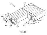
- FIG. 11 is a partially cutaway perspective view of a tank constituting a fifth embodiment of the present invention.
- FIG. 1 shows a tank 1 for storing gas at high pressure, and in a first embodiment of the invention this tank comprises a gas confinement volume 2 constituted by a spiral coil of a metal duct 3 about an axis ZZ′.
- the duct 3 has a section that is flat or oblong in shape and it is coiled as a plurality of adjacent turns to enable the turns to bear against one another via their substantially rectilinear elongate portions 10 , 11 with the exception of the innermost turn and of the outermost turn each of which has only one of its rectilinear portions bearing against an adjacent turn.
- Coiling a duct of flat section so that its turns touch enables the objects of the invention to be achieved, specifically it enables mass, bulk, and cost of the tank to be reduced compared with a conventional tank for storing the same quantity of gas.
- FIG. 2 is a section through the duct 3 showing two rectilinear elongate portions 10 , 11 interconnected by curvilinear portions 12 , 13 .
- the forces exerted by the gas pressure on the elongate portions 10 , 11 are represented by respective series of arrows F 1 and F 2 in a force-cancellation zone h.
- the forces exerted on the outside walls of the duct by the adjacent turns are represented by series of F 1 ′ and F 2 ′ in the zone h.
- the radial forces F 1 , F 2 exerted by the gas pressure inside the duct on the respective rectilinear portions 10 and 11 are compensated respectively by radial forces F 1 ′ and F 2 ′ exerted on the corresponding portions of adjacent turns.
- the gas pressure forces stress only the curvilinear portions 12 , 13 which are subjected respectively to axial forces F 3 and F 4 .
- the thickness of the duct wall can be reduced in proportion to the amount of compensation. Mechanically dimensioning the duct 3 to match the pressure thus amounts to dimensioning a tube of diameter D′ as constituted by combining the two curvilinear portions 12 and 13 .
- the wall thickness of the duct can be greater in the curvilinear portions 12 , 13 than in the rectilinear portions 10 , 11 .
- FIG. 10 shows a section of a tube 30 for containing gas at a given pressure.
- This section has a diameter D and a wall thickness e.
- the saving in mass per unit length is 50%. Nevertheless, it should be observed that the deformed section of the duct 3 is smaller than that of the original tube 30 . In the above example, the tube needs to be lengthened by 33% in order to contain the same volume. The actual saving in mass thus amounts to 33% overall and raises the structural ratio of a tank of the invention to better than 1.5 l/kg.
- the method of manufacture and the tank of the invention are described below with reference to a first embodiment shown in FIGS. 1 to 4 .
- the oblong section duct 3 can be obtained either at low cost by folding and welding a metal strip, or else by drawing a seamless tube, i.e. without any welds.
- One end 16 of the duct 3 as obtained in this way is shaped by metal working to have a cylindro-conical funnel shape 14 as shown in FIG. 4 serving to receive a coupling element 4 and a communication element 5 .
- the communication element 5 may comprise a valve, a piston, or any element enabling the tank to be selectively opened and closed for filling and delivery purposes.
- FIG. 3 shows the other end 15 of the duct 3 which is likewise shaped so as to taper progressively down to a tip which is closed by welding.
- the next operation consists in curving the duct 3 into a spiral coil beginning with the end 16 and ending with the opposite end 15 .
- This curving operation can be performed on a numerically controlled machine and, depending on the characteristics of the profile of the duct 3 , it can be done either by applying a determined pressure to the inside of the duct 3 , or by preheating it, or indeed by a combination of the two.
- the coil blank is then temporarily banded and subject to an appropriate heat-treatment cycle.
- the spiral coil of the duct 3 then becomes fixed in its final shape and needs to be reinforced at its outside surface 17 so as to conserve the coherence and reliability of the coil structure once the duct is under pressure.
- the turns of the duct 3 that bear against one another after the coiling operation may optionally have material interposed between them so as to reduce the friction forces between two rectilinear elongate portions 10 , 11 or 11 , 10 of two adjacent turns.
- the outer cylindrical surface 17 defined by the outermost turn of the coil is banded by winding carbon fiber or glass fiber to form an external hoop 7 surrounding the coil. Then an internal hoop 6 is put into place against the inside surface 9 of the coil.
- the internal hoop 6 comprises a metal ring potted in an epoxy type resin.
- An optional glass fiber protective wrapping 8 can be wound over the entire ring formed by the coil to protect it against impact and chemicals.
- the tank 1 as obtained in this way can for example present a storage capacity of 100 liters by using a coil having 7.5 turns with an outside diameter of 950 mm and an outside height of 190 mm.
- the outer hoop 7 could be made using a metal material.
- FIGS. 7, 8 , and 9 show respectively a second embodiment 100, a third embodiment 200, and a fourth embodiment 300 of the invention. These variant shapes comprise two variant spiral coils, and a coil that is of the helical type. It will be observed that all of the elements of the second, third, and fourth embodiments referenced in FIGS. 7, 8 , and 9 are equivalent in shape and function to elements of the first embodiment of the tank 1 of the invention and are therefore not described in detail.
- FIGS. 7, 8 , and 9 show the second, third, and fourth embodiments of the invention stripped of its covering, i.e. without the wound hoops and wrappings described with reference to FIG. 1 . The person skilled in the art will readily understand that those embodiments can be made to include these elements by implementing the manufacturing method described above.
- FIG. 7 shows a tank 100 shaped as a spiral coil using the manufacturing method described above with reference to FIG. 1, but presenting a final shape that is oval which is obtained by appropriate adjustments during the curving of the duct.
- a tank 200 of the invention can present the shape of an elongate rectangle as shown in FIG. 8 .
- the coiling of the turns begins at one end 315 , e.g. the end that tapers down to a welded tip, and it is coiled upwards about the axis ZZ′ to its other end 316 which is fitted with the coupling and communication means 304 , 305 .
- the set of juxtaposed turns serves to define the longitudinal dimension of the tank along the axis ZZ′.
- FIG. 11 A fifth embodiment of a tank of the invention is shown in FIG. 11 .
- the tank 400 is made by folding a duct 403 into a plurality of touching segments in a zigzag configuration with bends 420 .
- This disposition of the single duct 403 enables the effects desired for the invention to be obtained.
- the elongate portions 410 , 411 of touching segments do indeed bear against corresponding elongate portions of adjacent touching segments of the duct with the exception of the end lengths 416 , 415 which can respectively include either the coupling means 404 , 405 at one end and a tapering duct closure shape at the other end, or else coupling means at both ends.
- the fifth embodiment shown in FIG. 11 serves in particular to obtain tanks in the form of compact rectangular parallelepipeds without any empty space in the center of the tank.
- Tanks of the invention are well suited to storing gas at pressures that can be of the order of 200 bars, for example, or even higher. Such tanks can be of reduced mass, particularly if they are made of a material such as aluminum.
- a tank of the invention When a tank of the invention is integrated in a vehicle, it will be observed that from the safety point of view, because of its shape that implements pseudo-partitioning, the effects of a sudden loss of pressure, e.g. due to an impact, are moderated by the inertia of the stored mass.
- the tank has considerable capacity for absorbing impact in a plane that contains the large dimension of the tank (plane perpendicular to the axis ZZ′ in the embodiments of FIGS. 1, 7 , and 8 , an axial plane containing the axis ZZ′ for the embodiment of FIG. 9, and the lateral plane for the embodiment of FIG. 11 ), with the tank then presenting itself in the form of an elastic “sandwich” structure placed in a vehicle in such a manner as to be suitable for absorbing the kind of impact that is most frequent in this type of use, i.e. lateral impacts.
Landscapes
- Engineering & Computer Science (AREA)
- Mechanical Engineering (AREA)
- General Engineering & Computer Science (AREA)
- Filling Or Discharging Of Gas Storage Vessels (AREA)
Applications Claiming Priority (2)
| Application Number | Priority Date | Filing Date | Title |
|---|---|---|---|
| FR9915957A FR2802612B1 (fr) | 1999-12-17 | 1999-12-17 | Reservoir pour stockage de gaz a haute pression |
| FR9915957 | 1999-12-17 |
Publications (2)
| Publication Number | Publication Date |
|---|---|
| US20010004902A1 US20010004902A1 (en) | 2001-06-28 |
| US6659303B2 true US6659303B2 (en) | 2003-12-09 |
Family
ID=9553396
Family Applications (1)
| Application Number | Title | Priority Date | Filing Date |
|---|---|---|---|
| US09/738,261 Expired - Fee Related US6659303B2 (en) | 1999-12-17 | 2000-12-15 | Tank for storing gas at high pressure |
Country Status (8)
| Country | Link |
|---|---|
| US (1) | US6659303B2 (es) |
| EP (1) | EP1108946A1 (es) |
| JP (1) | JP2001214997A (es) |
| KR (1) | KR20010062514A (es) |
| CN (1) | CN1306173A (es) |
| AR (1) | AR026965A1 (es) |
| CA (1) | CA2328542A1 (es) |
| FR (1) | FR2802612B1 (es) |
Cited By (10)
| Publication number | Priority date | Publication date | Assignee | Title |
|---|---|---|---|---|
| US20070075085A1 (en) * | 2005-10-04 | 2007-04-05 | Gerd Arnold | Tube shaped high pressure storage tank |
| US20100258571A1 (en) * | 2006-10-26 | 2010-10-14 | Altair Engineering, Inc. | Storage Tank Containment System |
| US8851321B2 (en) | 2006-10-26 | 2014-10-07 | Altair Engineering, Inc. | Storage tank containment system |
| US9636652B2 (en) | 2013-12-05 | 2017-05-02 | Exxonmobil Research And Engineering Company | Reactor bed vessel and support assembly |
| US9708120B2 (en) | 2006-10-26 | 2017-07-18 | Altair Engineering, Inc. | Storage tank containment system |
| DE102016208319A1 (de) * | 2016-05-13 | 2017-11-16 | Bayerische Motoren Werke Aktiengesellschaft | Fahrzeugtank für Flüssigkeiten |
| US10352500B2 (en) | 2006-10-26 | 2019-07-16 | Altair Engineering, Inc. | Storage tank containment system |
| US10406497B2 (en) | 2013-12-05 | 2019-09-10 | Exxonmobil Research And Engineering Company | Reactor bed vessel and support assembly |
| US10876686B2 (en) | 2017-08-31 | 2020-12-29 | Altair Engineering, Inc. | Storage tank containment system |
| US11098850B2 (en) | 2006-10-26 | 2021-08-24 | Altair Engineering, Inc. | Storage tank containment system |
Families Citing this family (15)
| Publication number | Priority date | Publication date | Assignee | Title |
|---|---|---|---|---|
| CN2644355Y (zh) * | 2003-09-22 | 2004-09-29 | 牛长义 | 扁形吸管 |
| DE102004041448B3 (de) * | 2004-08-27 | 2005-11-17 | Dräger Medical AG & Co. KGaA | Druckbeständiger Flüssigkeitstank |
| DE102007048096B4 (de) * | 2007-10-05 | 2009-07-09 | Benteler Automobiltechnik Gmbh | Kraftfahrzeug |
| JP5511113B2 (ja) * | 2010-10-06 | 2014-06-04 | エルピガス エスペー ゾオ | 圧力タンク |
| EP2844906B1 (en) * | 2012-05-03 | 2020-09-16 | Other Lab, LLC | Conforming natural energy storage |
| DE102013002944A1 (de) * | 2013-02-21 | 2014-08-21 | Daimler Ag | Vorrichtung zum Speichern von Gas unter hohem Druck |
| US9759379B2 (en) * | 2014-05-15 | 2017-09-12 | Sea Ng Corporation | Gas storage structure and method of manufacture |
| JP6778216B2 (ja) | 2015-06-15 | 2020-10-28 | アザー ラブ リミテッド ライアビリティ カンパニー | 形状適合型圧力容器のためのシステムおよび方法 |
| DE102016110171B4 (de) * | 2015-07-31 | 2017-10-12 | Csi Entwicklungstechnik Gmbh | Speicherbehälter |
| CN108431486A (zh) | 2015-12-02 | 2018-08-21 | 奥特尔实验室有限责任公司 | 用于衬筒编织和树脂涂敷的系统和方法 |
| US10851925B2 (en) | 2016-10-24 | 2020-12-01 | Other Lab, Llc | Fittings for compressed gas storage vessels |
| US20180283612A1 (en) | 2017-03-31 | 2018-10-04 | Other Lab, Llc | Tank filling system and method |
| DE102018218421A1 (de) * | 2018-10-29 | 2020-04-30 | Robert Bosch Gmbh | Einrichtung zur Speicherung von verdichteten Fluiden |
| CN114076255A (zh) * | 2021-08-31 | 2022-02-22 | 海鹰空天材料研究院(苏州)有限责任公司 | 一种一端封底超大尺寸铝合金内胆高压全缠绕气瓶及其制造方法 |
| CN115593809B (zh) * | 2022-12-15 | 2023-04-07 | 中国电建集团华东勘测设计研究院有限公司 | 气水共容罐及抽水压缩空气储能系统 |
Citations (13)
| Publication number | Priority date | Publication date | Assignee | Title |
|---|---|---|---|---|
| US1645944A (en) * | 1923-12-04 | 1927-10-18 | Debor Hermann | Shell-shaped body suitable for the allowance of high-pressure stresses |
| US2250250A (en) * | 1938-09-22 | 1941-07-22 | New York Tank Co | Symmetrically shaped and easily duplicated pressure tank |
| US2451486A (en) * | 1944-09-01 | 1948-10-19 | Chicago Bridge & Iron Co | Vacuum tank for storing liquids at high or low temperatures |
| US3252610A (en) * | 1963-10-30 | 1966-05-24 | Chrysler Corp | Tubular wall reinforced pressure vessel |
| US3409061A (en) * | 1967-03-06 | 1968-11-05 | Arthur D. Struble Jr. | All-plastic, non-rigid cryogenic container |
| US3432060A (en) * | 1965-04-23 | 1969-03-11 | Therapeutic Research Corp Ltd | Tubular pressure vessel |
| US3472414A (en) * | 1965-12-16 | 1969-10-14 | Edouard Georges Daniel Rodrigu | Containers and the like |
| US3505996A (en) * | 1967-03-31 | 1970-04-14 | Abbott Lab | High pressure gas storage and discharge apparatus |
| DE2305840A1 (de) | 1973-02-07 | 1974-08-08 | Wankel Felix Dr Ing H C | Transportabler druckgasbehaelter |
| US4561476A (en) * | 1984-10-11 | 1985-12-31 | The Garrett Corporation | Toroidal pressure vessel |
| US4576015A (en) | 1983-04-14 | 1986-03-18 | Crawford A Gerrit | Lightweight high pressure tubular storage system for compressed gas and method for cryogenic pressurization |
| FR2739912A1 (fr) | 1995-10-17 | 1997-04-18 | Sardou Max | Reservoir moyenne pression a structure multicellulaire moyenne pression et son procede de fabrication |
| WO1999019203A1 (en) | 1997-10-15 | 1999-04-22 | Enron Lng Development Corp. | Ship based gas transport system |
-
1999
- 1999-12-17 FR FR9915957A patent/FR2802612B1/fr not_active Expired - Fee Related
-
2000
- 2000-12-14 EP EP20000403513 patent/EP1108946A1/fr not_active Withdrawn
- 2000-12-15 US US09/738,261 patent/US6659303B2/en not_active Expired - Fee Related
- 2000-12-15 AR ARP000106657 patent/AR026965A1/es unknown
- 2000-12-15 CA CA 2328542 patent/CA2328542A1/en not_active Abandoned
- 2000-12-15 CN CN00135693A patent/CN1306173A/zh active Pending
- 2000-12-16 KR KR1020000077420A patent/KR20010062514A/ko not_active Application Discontinuation
- 2000-12-18 JP JP2000383819A patent/JP2001214997A/ja active Pending
Patent Citations (13)
| Publication number | Priority date | Publication date | Assignee | Title |
|---|---|---|---|---|
| US1645944A (en) * | 1923-12-04 | 1927-10-18 | Debor Hermann | Shell-shaped body suitable for the allowance of high-pressure stresses |
| US2250250A (en) * | 1938-09-22 | 1941-07-22 | New York Tank Co | Symmetrically shaped and easily duplicated pressure tank |
| US2451486A (en) * | 1944-09-01 | 1948-10-19 | Chicago Bridge & Iron Co | Vacuum tank for storing liquids at high or low temperatures |
| US3252610A (en) * | 1963-10-30 | 1966-05-24 | Chrysler Corp | Tubular wall reinforced pressure vessel |
| US3432060A (en) * | 1965-04-23 | 1969-03-11 | Therapeutic Research Corp Ltd | Tubular pressure vessel |
| US3472414A (en) * | 1965-12-16 | 1969-10-14 | Edouard Georges Daniel Rodrigu | Containers and the like |
| US3409061A (en) * | 1967-03-06 | 1968-11-05 | Arthur D. Struble Jr. | All-plastic, non-rigid cryogenic container |
| US3505996A (en) * | 1967-03-31 | 1970-04-14 | Abbott Lab | High pressure gas storage and discharge apparatus |
| DE2305840A1 (de) | 1973-02-07 | 1974-08-08 | Wankel Felix Dr Ing H C | Transportabler druckgasbehaelter |
| US4576015A (en) | 1983-04-14 | 1986-03-18 | Crawford A Gerrit | Lightweight high pressure tubular storage system for compressed gas and method for cryogenic pressurization |
| US4561476A (en) * | 1984-10-11 | 1985-12-31 | The Garrett Corporation | Toroidal pressure vessel |
| FR2739912A1 (fr) | 1995-10-17 | 1997-04-18 | Sardou Max | Reservoir moyenne pression a structure multicellulaire moyenne pression et son procede de fabrication |
| WO1999019203A1 (en) | 1997-10-15 | 1999-04-22 | Enron Lng Development Corp. | Ship based gas transport system |
Cited By (17)
| Publication number | Priority date | Publication date | Assignee | Title |
|---|---|---|---|---|
| US20070075085A1 (en) * | 2005-10-04 | 2007-04-05 | Gerd Arnold | Tube shaped high pressure storage tank |
| DE102006046722B4 (de) * | 2005-10-04 | 2009-04-23 | GM Global Technology Operations, Inc., Detroit | Rohrförmiger Hochdruck-Speichertank |
| US7624761B2 (en) | 2005-10-04 | 2009-12-01 | Gm Global Technology Operations, Inc. | Tube shaped high pressure storage tank |
| US9321588B2 (en) | 2006-10-26 | 2016-04-26 | Altair Engineering, Inc. | Storage tank containment system |
| US9708120B2 (en) | 2006-10-26 | 2017-07-18 | Altair Engineering, Inc. | Storage tank containment system |
| US8851321B2 (en) | 2006-10-26 | 2014-10-07 | Altair Engineering, Inc. | Storage tank containment system |
| US8851320B2 (en) | 2006-10-26 | 2014-10-07 | Altair Engineering, Inc. | Storage tank containment system |
| US9175806B2 (en) | 2006-10-26 | 2015-11-03 | Altair Engineering, Inc. | Storage tank containment system |
| US20100258571A1 (en) * | 2006-10-26 | 2010-10-14 | Altair Engineering, Inc. | Storage Tank Containment System |
| US11098850B2 (en) | 2006-10-26 | 2021-08-24 | Altair Engineering, Inc. | Storage tank containment system |
| US8322551B2 (en) * | 2006-10-26 | 2012-12-04 | Altair Engineering, Inc. | Storage tank containment system |
| US10352500B2 (en) | 2006-10-26 | 2019-07-16 | Altair Engineering, Inc. | Storage tank containment system |
| US10406497B2 (en) | 2013-12-05 | 2019-09-10 | Exxonmobil Research And Engineering Company | Reactor bed vessel and support assembly |
| US9636652B2 (en) | 2013-12-05 | 2017-05-02 | Exxonmobil Research And Engineering Company | Reactor bed vessel and support assembly |
| DE102016208319A1 (de) * | 2016-05-13 | 2017-11-16 | Bayerische Motoren Werke Aktiengesellschaft | Fahrzeugtank für Flüssigkeiten |
| US10876686B2 (en) | 2017-08-31 | 2020-12-29 | Altair Engineering, Inc. | Storage tank containment system |
| US11493173B2 (en) | 2017-08-31 | 2022-11-08 | Altair Engineering, Inc. | Storage tank containment system |
Also Published As
| Publication number | Publication date |
|---|---|
| CA2328542A1 (en) | 2001-06-17 |
| KR20010062514A (ko) | 2001-07-07 |
| AR026965A1 (es) | 2003-03-05 |
| FR2802612A1 (fr) | 2001-06-22 |
| FR2802612B1 (fr) | 2002-03-29 |
| EP1108946A1 (fr) | 2001-06-20 |
| JP2001214997A (ja) | 2001-08-10 |
| US20010004902A1 (en) | 2001-06-28 |
| CN1306173A (zh) | 2001-08-01 |
Similar Documents
| Publication | Publication Date | Title |
|---|---|---|
| US6659303B2 (en) | Tank for storing gas at high pressure | |
| EP2418412B1 (en) | Tank and fabrication method thereof | |
| US3432060A (en) | Tubular pressure vessel | |
| US7744127B2 (en) | Fuel tank mount | |
| US5385262A (en) | Vessel for storing fluid under pressure able to undergo rupture without fragmentation | |
| WO2011154994A1 (ja) | 高圧タンクおよび高圧タンクの製造方法 | |
| MXPA95005276A (es) | Modulo movil de almacenamiento de gas comprimido y cilindros compuestos de peso ligero. | |
| JPH10152U (ja) | 圧力媒体を蓄える圧力容器 | |
| US5830400A (en) | Method of manufacturing a hollow structure for storing pressurized fluids | |
| EP4050249A1 (en) | High-pressure gas storage system having adaptable morphology | |
| KR102251861B1 (ko) | 고압 탱크 | |
| JP4849324B2 (ja) | 高圧タンク | |
| KR102322371B1 (ko) | 실린더부가 보강된 압력 용기 | |
| JP2001021099A (ja) | 圧力容器 | |
| CN101936452A (zh) | 高压气瓶 | |
| CN115143384A (zh) | 高压储罐及其制造方法 | |
| JPH10274391A (ja) | 耐外圧性に優れたfrp圧力容器 | |
| JP7493409B2 (ja) | 一般複合容器 | |
| US20240068624A1 (en) | Gas cylinder bundle | |
| JPH0972494A (ja) | Frp複合容器 | |
| US20220412508A1 (en) | Tank and method of manufacturing the same | |
| JP2008057632A (ja) | 流体貯蔵タンク | |
| JP2020112234A (ja) | 圧力容器 | |
| JP2023180534A (ja) | 高圧タンク用プロテクタおよび高圧タンク | |
| JP2020037961A (ja) | タンクの製造方法 |
Legal Events
| Date | Code | Title | Description |
|---|---|---|---|
| AS | Assignment |
Owner name: SNECMA MOTEURS, FRANCE Free format text: ASSIGNMENT OF ASSIGNORS INTEREST;ASSIGNOR:GARCEAU, PATRICK;REEL/FRAME:011614/0119 Effective date: 20010126 |
|
| REMI | Maintenance fee reminder mailed | ||
| LAPS | Lapse for failure to pay maintenance fees | ||
| STCH | Information on status: patent discontinuation |
Free format text: PATENT EXPIRED DUE TO NONPAYMENT OF MAINTENANCE FEES UNDER 37 CFR 1.362 |
|
| FP | Lapsed due to failure to pay maintenance fee |
Effective date: 20071209 |
|
| AS | Assignment |
Owner name: SNECMA, FRANCE Free format text: CHANGE OF NAME;ASSIGNOR:SNECMA MOTEURS;REEL/FRAME:020609/0569 Effective date: 20050512 Owner name: SNECMA,FRANCE Free format text: CHANGE OF NAME;ASSIGNOR:SNECMA MOTEURS;REEL/FRAME:020609/0569 Effective date: 20050512 |