US6651014B2 - Apparatus for automatically measuring the resistivity of semiconductor boules by using the method of four probes - Google Patents
Apparatus for automatically measuring the resistivity of semiconductor boules by using the method of four probes Download PDFInfo
- Publication number
- US6651014B2 US6651014B2 US10/138,835 US13883502A US6651014B2 US 6651014 B2 US6651014 B2 US 6651014B2 US 13883502 A US13883502 A US 13883502A US 6651014 B2 US6651014 B2 US 6651014B2
- Authority
- US
- United States
- Prior art keywords
- probe
- boule
- axis
- resistivity
- computer processor
- Prior art date
- Legal status (The legal status is an assumption and is not a legal conclusion. Google has not performed a legal analysis and makes no representation as to the accuracy of the status listed.)
- Expired - Fee Related
Links
Images


Classifications
-
- G—PHYSICS
- G01—MEASURING; TESTING
- G01R—MEASURING ELECTRIC VARIABLES; MEASURING MAGNETIC VARIABLES
- G01R27/00—Arrangements for measuring resistance, reactance, impedance, or electric characteristics derived therefrom
- G01R27/02—Measuring real or complex resistance, reactance, impedance, or other two-pole characteristics derived therefrom, e.g. time constant
- G01R27/08—Measuring resistance by measuring both voltage and current
-
- G—PHYSICS
- G01—MEASURING; TESTING
- G01N—INVESTIGATING OR ANALYSING MATERIALS BY DETERMINING THEIR CHEMICAL OR PHYSICAL PROPERTIES
- G01N27/00—Investigating or analysing materials by the use of electric, electrochemical, or magnetic means
- G01N27/02—Investigating or analysing materials by the use of electric, electrochemical, or magnetic means by investigating impedance
- G01N27/04—Investigating or analysing materials by the use of electric, electrochemical, or magnetic means by investigating impedance by investigating resistance
- G01N27/041—Investigating or analysing materials by the use of electric, electrochemical, or magnetic means by investigating impedance by investigating resistance of a solid body
-
- G—PHYSICS
- G01—MEASURING; TESTING
- G01R—MEASURING ELECTRIC VARIABLES; MEASURING MAGNETIC VARIABLES
- G01R31/00—Arrangements for testing electric properties; Arrangements for locating electric faults; Arrangements for electrical testing characterised by what is being tested not provided for elsewhere
- G01R31/26—Testing of individual semiconductor devices
- G01R31/2648—Characterising semiconductor materials
Definitions
- the invention relates to machines for measuring the electrical resistivity of bulk materials; and in particular to a machine for the automated, multi-point, multi-surface measurement of the resistivity of a semiconductor boule.
- ⁇ is the resistivity measured by a collinear four point probe
- s is the spacing of the probes
- V is the measured voltage
- I is the source current
- the correction factor accounts for several variables: the thickness of the sample under investigation, location of the probe from the wafer edge, diameter of the sample and location of the current and voltage probes. In addition there is a correction for temperature.
- temperature plays an important role. Therefore corrections should be made for the measured temperature. It is also important to choose the magnitude of the current to be used for measurement to prevent minority carrier injection as well as localized sample heating.
- equation 3 becomes the control equation since one is measuring bulk resistivity at all times.
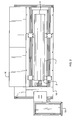
- FIG. 1 is an upper right, operator's side, perspective view of a preferred embodiment of the invention, showing the enclosed steel frame, open cover, probe head at the front end of the frame in home position, carriage rails, four boule supports and support rails, and computer and keyboard tray attached to the front end of the frame.
- FIG. 2 is top view of the FIG. 1 embodiment, but with a boule in position for being measured and the probe in proximity to the first face end of the boule.
- FIG. 3 is a front end elevation of the embodiment of FIG. 1 with the end panel removed but with power and sensor lines and hoses not shown.
- FIG. 4 is an operator's side, elevation of the embodiment of FIG. 1, cover open, panel off, with the probe positioned at the centerpoint of the first face end of a boule as for a resistivity reading.
- FIG. 5 is an operator's side, elevation of the embodiment of FIG. 4, but with the probe underneath the boule and pointed upward to sense proximity as when traversing from one end to the other.
- FIG. 6 is another operator's side, elevation of the embodiment of FIG. 4, but with the probe at the centerpoint of the second face end of the boule at the aft end of the frame as for a resistivity reading.
- FIG. 7 is a close up perspective view of the probe, probe shaft and pulley, and yoke, with the four point probe head and four probe tips and one of two optical sensors clearly visible on the probe head face.
- FIG. 8 is a perspective view of the probe mounted on the probe carriage assembly of the preferred embodiment, with belt driven rotational motion for the probe, and vertical and crosswise linear motion incorporated directly into the probe carriage, which gets lengthwise linear motion by riding on lengthwise rails in the frame underneath the boule support rails.
- FIG. 9 is a diagrammatic view of the control elements of the embodiment of FIG. 1, with power, computer, breakout box, source meter, and four-point probe illustrated.
- FIG. 10 is a representative printout of a ten point resistivity reading, identified by the ID number of the boule to which it applies.
- FIGS. 1-8 there is shown a preferred embodiment of the fully automatic measurement system of the invention, with enclosure panels 17 on in some figures and removed in others, and cover 16 open.
- the computer and keyboard tray 19 and the probe home position shroud 18 are at the front end of frame 10 .
- FIG. 1 there is shown left and right side boule support rails 20 .
- a semiconductor ingot or boule 1 is shown in position on the four point support grid in other than FIG. 1 .
- Boule 1 is a cylindrical bulk of silicon, in the preferred embodiment up to 51 inches in length, 100 to 200 millimeters in diameter, and weighing up to 300 pounds and more, for which electrical resistivity measurements are required.
- the boule has a cropped forward or first end surface 2 , cylinder sidewall surface 3 , and cropped aft or second end surface 4 , which are the surfaces upon which the “four probe” method of resistivity measurement is applied.
- the end surface measurements are referred to as radial resistivity measurements; while the sidewall measurements are referred to as axial resistivity measurements.
- a probe carriage assembly 40 riding on parallel carriage support rails 30 below boule support rails 20 , is comprised of a four point probe head 50 rotatingly mounted in yoke 42 at the top of vertically adjustable post 44 , attached by a collar to cross carriage 46 , which rides on cross rails 48 .
- Probe head 50 is configured with a C4S-67TM standard four-point probe 54 with probe spacing 1.55 mm and tungsten carbide probe tips. Probe pressure varies from 70 grams to 180 grams per probe. Four point probe 54 is actuated electrically for resistivity measurements when probe 50 is in the desired position with four point probe 54 in contact with the boule surface.
- Probe head rotation is provided by pulley and shaft 51 , which is oriented horizontal and parallel to cross rails 48 , and at right angles to the lengthwise orientation of frame 10 and carriage support rails 30 , so that probe head 50 can be rotated to point upward, or towards either end of frame 10 .
- Motor 52 and probe angle drive belt 53 extending along post 44 to shaft 51 , provides for angular position control of probe 50 within yoke 42 .
- Post 44 is vertically adjustable in the z axis by motorized lead screw 45 .
- Cross carriage 46 is motorized for lateral motion in the y axis along cross rails 48 .
- the complete probe head carriage assembly is motorized and configured with twin, teethed drive belts 49 for movement along the x axis, on probe carriage support rails 30 .
- the various stepper motors providing motion in the preferred embodiment are controlled by IM483TM micro stepping drives, controlled by a PCITM Next Move drive control card in computer 13 of FIG. 9 . It will be apparent from the above that three axis linear and single axis rotational adjustment are available to probe head 50 by these mechanisms, so that four-point probe 54 can be oriented and operated by computer control for automated surface mapping and sequential resistivity checks on boule 1 , first end surface 2 ; along the underside length of sidewall surface 3 ; and on second end surface 4 . A centerline track of the probe head assembly through frame 10 under the boule simplifies the routing of supporting electrical connections between probe head 50 and respective power and computer control box terminations mounted within or proximate to frame 10 .
- the preferred embodiment can accommodate semiconductor boule diameters of 100 to 200 millimeters (mm). No adjustment, other than to the aft end boule supports 22 in the case of shorter than usual boules, need to be made while maintaining a clear pathway underneath the boule for transiting of probe carriage assembly 40 on carriage rails 30 over the length of the frame without obstructing access to the necessary boule surface areas.
- the machine frame can be of any useful length, with adequate supports, to accommodate the longest boule, and can be scaled in width for larger and smaller diameter boules if required, as for example up to 300 millimeters or larger.
- Boules are introduced to the apparatus by manually controlled or by automated transport mechanisms, by being placed lengthwise onto the boule support grid. It is not required to bring the boule to an exact position; it needs only to be placed with its forward end in the near vicinity of the home position of the probe, with the forward end boule supports 22 having be previously adjusted so as not to extend significantly out from under the usual boule placement position where interference with probe head motion might occur.
- a computerized probe head mapping sequence provides for automatically locating and measuring the boule within the placement area, as will be further described below.
- the four supports 22 for the boule are cantilevered off frame members 20 and cushioned with a non-conductive material, a firm rubber cushion that is configured with a nearly square support edge.
- the boule rests on a longitudinal outside edge of the rubber cushion on all four supports.
- the long edge of the rubber form inhibits slippage of the boule, lengthwise in particular, during the measurement cycle.
- the rubber edge allows the boule to be partially lifted by the operator and rotated easily about its axis if repositioning is required for any reason.
- a rectangular, four point support grid is especially suitable for a cylindrical form such as a boule, as the cylinder wall is self centering within each of the two end pairs of supports.
- the front or forward pair of supports 22 which is closer to the home position of the probe is fixed to coincide with where the boule end is normally placed.
- the rear or aft end pair of supports 22 are adjustable on rails 20 for lengthwise positioning suitable for the normal length of boules handled, but can be manually repositioned if required, as when the length of the next boule is out of the range of the previous setting. This allows a wide range of length of boules to be handled on the machine. In other embodiments, this adjustment can be automated if boule length is known or is measurable in advance of placement on the support grid.
- a binding strap (not shown) may be attached to forward end supports 22 and manually positioned over the top of the boule and secured to prevent the boule from slipping or tilting during measurements. This optional security measure may also be automated in other embodiments, if shorter boules are the norm.
- a power source 11 for controlling and sensing the current conditions of the four point probe 54 for the resistivity measurements in accordance with the conventional four probe resistivity methodology.
- a fan (not shown) that provides an airflow under slight positive air pressure from a clean air source, when the cover 16 is closed for measurement, to inhibit infiltration of foreign matter into the cabinet during the measurement cycle.
- computer processor 13 is an industrial computer running on a WINDOWS® NT operating platform.
- a commercial control software package TEST POINT® (CEC) or LABVIEW® is used with apparatus specific, custom programming to enhance the operator interface and machine operation.
- Source meter 15 is a high precision programmable constant current KEITILY® source (Model 2400). This model also has a voltage read out facility. Analog to digital interface boards arc used as interface signals from the voltmeter to the computer to a General Purpose Interface Bus (GPIB).
- GPIB General Purpose Interface Bus
- a data entry screen on the operator control/display 12 provides for entering boule identification and other related data for each boule being measured, so that a permanent record of the boule characteristics and resistivity measurements is available for later reference.
- Computer 13 can be networked in any useful manner to coordinate delivery and removal of boules, receive special operating instructions or boule identification data, and share measurement data.
- the probe is set automatically to the home position within shroud 18 , stowed out of the way as in FIG. 1, before the boule is placed on the table.
- the home position is arranged during setup to be a couple of inches away from the forward or first end 2 position where the delivery system will normally place the boule or ingot.
- the mapping sequence occurs first. On the start command, when cover 16 is sensed to be closed, positive air pressure is sensed, and no other safety lockouts are present, probe 50 is rotated to have four point probe 54 directed towards the expected boule position, and probe carriage 40 is advanced on carriage rails 30 towards face 2 of boule 1 until optical sensors 55 on probe 50 signal proximity of boule face 2 , which indicates the lengthwise or X axis location of the first end of the boule. Probe head 50 is then adjusted vertically while sensors 55 are monitored for surface continuity, until the top edge and bottom edge, or Z axis dimensions, of face 2 are established, permitting the computer processor to calculate the boule diameter and the centerpoint.
- a logic pattern is then set where the computer processor automatically calculates the current to be used for the boule under test.
- Probe 50 moves to the center of the boule face and takes a first reading to establish the correct current or “set” current for all measurements on this boule.
- Probe head 50 now swings 90 degree upwards and probe carriage 40 moves aft on rails 30 , driven by belts 49 below and along the boule.
- the same two strategically placed laser sensors 55 on probe 50 are used to sense surface proximity and continuity as the carriage is advanced by teethed belts 49 along rails 30 .
- the continuity ends the aft end X axis location of the boule is presumed to have been found, thus providing the data for calculating the length of the boule.
- Probe head 50 is elevated and positioned sequentially according to the predetermined recipe. At each position, four point probe 54 is moved forward to make contact with face 4 . This is done by a specially spring loaded probe mount on which the four probes are mounted. The probe mount will assure that even if there is a slight taper on the face of the boule, all four probes will make proper contact.
- a constant current level of electricity previously determined by the computer control system during the face 2 set current function, is passed through the boule by the outer two probes in the manner known in the art. The voltage that is developed across the inner two probes is measured simultaneously. Then the polarity of the current in the outer probes is reversed. The above procedure is repeated. The arithmetic average of the two ratios of voltage to current, in other words the electrical resistivity as per equation 3, is computed and stored in memory. The probes are retracted for the next probe head movement and measurement.
- mapping patterns on the face of the boule that are recommended as per ASTM standards.
- the probe has to move to the different required positions on the face of the boule end, such movement being within the three axis motion capability described. Since the center and the diameter is known after the preliminary mapping of the first end 2 , the probe can by standard pattern or recipe provided by computer processor 13 move the probe to any of the required points. Resistivity readings can be taken at all points and data logged in the control computer or remotely. If the user so requires, the system can be programmed to map other than industry standard patterns. For user defined positions, a recipe is first generated. This is done by defining the number of points to be mapped, and converting the points to be mapped into polar coordinates.
- the recipe is stored in a recipe file which can be accessed by the program.
- the resistivity measurements are done as described, such as on the center alone, or at five points or nine points or as otherwise may be required and programmed. After the face 4 measurements, if axial resistivity is not required, the probe is returned to its home position.
- the boule has generally been surface ground earlier to obtain a uniform diameter and wall surface. If starting from home position, the probe moves from its home position and locates the face of the boule as previously described. The probe then slides below the boule starts moving along the sidewall surface below the boule, again as previously described. At preprogrammed positions lengthwise of the boule, the four point probe 54 is elevated and measures the resistivity at that point. It then drops back and moves to the next point along the length of the boule, and makes the measurement again and so on.
- the axial resistivity is to be done concurrently with a radial measurement cycle, it is done after measuring the resistivity on face 4 of the boule. Having already measured the length of the boule using sensors 55 on the probe head during the motion from the front end to the aft end of the boule, computer processor 13 has the information from which to calculate the number of points, spacing and position for the sidewall measurements for axial resistivity. The operator can specify a different or additional number of readings if desired.
- Four point probe head 54 is elevated at the prescribed points along the underside surface 3 of boule 1 while probe 50 is traversed back towards the front end of the frame and its home position. As before, all data is logged automatically.
- proximity sensors 55 are optical sensors that signal proximity of the probe 50 to the boule surface.
- the preferred embodiment also has several induction sensors (not shown) connected to the motor controller breakout box 14 and monitored via the program running on computer processor 13 .
- a Home Position Sensor that signals a home position for the rotation of the probe on shaft 51 . When this sensor is triggered the probe rotation is at its rotational component of home position.
- Home position also requires cross carriage 46 be at the centerline with respect to the Y axis, and typically at lower range Z axis and at the front end limit of the X axis.
- Y Axis Sensors signal Y axis limit positions of the probe head cross carriage 46 on probe carriage 40 .
- the resistivity corrected to 23° C. is given by
- the resistivity units are measured in ohm.cm.
- the data produced by the automated performance of the apparatus may be printed in the form of a report, as illustrated by the example of FIG. 8, where an actual ten point resistivity measurement, including forward, reverse and average resistivity, and temperature corrected resistivity, of a boule identified with an Ingot ID Number is documented.
- the computer is fully equipped with networking capabilities. Data can be stored in several different formats and analyzed. Operators are warned if the readings are out of range. Automatic voltage limit lockouts are provided if the high voltages are sensed due to improper contacts or large resistance when the probes contact the boule. Emergency switches are provided on the machine for the operator to stop operations at any time. Controls to move the probe away are then facilitated by manual operations using controls on the screen. If no boule is placed on the machine and operations are started, the machine will record an error message and will not proceed further.
- an automated measurement system for measuring resistivity of semiconductor boules according to a four probe methodology, consisting of a four point probe with a home position, where the probe is configured with three axis linear motion capability and at least one axis rotation capability, where the linear motion capability and the rotation capability are connected to a power source and controlled by a computer processor for departing from and returning to the home position.
- the four point probe is connected to a current source and a voltage sensor according to four probe methodology, and is further connected to and controlled by the computer processor.
- a boule support grid for supporting a boule with a first face end and a second face end in a horizontal orientation with the first face near the home position, and with the first face and the underside surface centerline and the second face exposed for access by and within reach of the four point probe through its three axis motion capability.
- the computer processor has program steps for directing a boule locating sequence by the four point probe and sensor beginning from the home position and exploring the first face and the underside surface centerline and the second face of the boule, and for deriving the boule diameter and boule length from the data acquired from exploring the boule surfaces.
- the computer processor has program steps for testing a selected point on said boule with the four point probe and calculating a set current according to four probe methodology.
- the computer processor has program steps for conducting radial resistivity measurements with the four point probe of at least one face of the boule.
- the computer processor also has program steps for conducting axial resistivity measurements of the underside surface centerline of the boule.
- the system may have a frame with spaced apart parallel boule support rails, where the boule support grid is made up of fore and aft end boule supports attached to each boule support rail so as to form a four point support grid, with the fore end boule supports located near the probe's home position.
- the system may have a probe carriage to which the probe is attached, where the probe carriage has three axis linear motion capability; the three axis linear motion consisting of lengthwise of the frame as X axis, crosswise of the frame as Y axis and vertical motion as Z axis.
- the four point probe may be mounted by a probe shaft on a Z axis adjustable support post on the probe carriage.
- the frame may have at least one X axis carriage rail, and preferably two parallel rails, upon which the probe carriage travels.
- the probe carriage may have at least one Y axis rail, and preferably two rails, upon which the probe cross carriage and four point probe travels.
- the probe's rotational capability may be provided by a probe shaft in a yoke.
- the system may have stepper motors connected to and controlled by the computer processor for rotating and moving the four point probe and moving the probe carriage.
- the computer processor may be connectable or connected to a computer network.
- the system may be cooperatively operated with an automated system of sequential delivery and removal of boules as in a production environment.
- the system may be substantially enclosed and have a cover closable over a boule on the support grid.
- There may be an air temperature sensor communicating with the computer processor.
- There may be positive pressure airflow source into the enclosed system.
- the steps for directing a boule locating sequence by the four point probe and sensor from home position to first end face and to the underside surface centerline and to the second end face, and for deriving boule face diameter and centerpoint and boule length from that data may include: beginning with the four point probe in the home position and pointed towards the boule support grid where the boule is expected to be; and advancing the four point probe from home position on centerline of the boule support grid towards the first face end until the probe sensor indicates proximity to the first face of the boule, thereby indicating X axis location of said first face.
- the steps for testing a selected point on the boule with the four point probe and calculating a set current according to four probe methodology may include the steps: beginning with the four point probe proximate the first face as indicated by the sensor; moving the four point probe to the centerpoint location on the first face; advancing the probe tips of four point probe into contact with the first face; applying a predetermined test current and sensing a response voltage; and calculating there from a suitable set current for the resistivity testing of the boule according to four probe methodology.
- the steps for conducting radial resistivity measurements with a four point probe of at least one face of the boule may include the steps: beginning with the four point probe proximate the face as indicated by the probe sensor; moving the four point probe along the face to a first radial measurement position of a predetermined face pattern of resistivity measurements; advancing the probe tips of the four point probe into contact with said face; applying the set current and sensing a response voltage; and calculating there from a radial resistivity value according to four probe methodology; and repeating the above steps for additional radial measurement positions of the selected pattern until all positions are measured.
- the steps for conducting axial resistivity measurements with the four point probe of the underside surface centerline of the boule may include: beginning with the four point probe proximate the underside surface centerline as indicated by the probe sensor; moving the four point probe along the surface centerline to a first axial measurement position of a predetermined pattern of axial resistivity measurements; advancing the probe tips of the four point probe into contact with the face; applying the set current and sensing a response voltage and calculating there from a radial resistivity according to four probe methodology; and repeating these steps for additional axial measurement positions until all positions of the selected pattern are measured.
- the program steps of the computer processor may include: making a record of boule diameter, boule length, and resistivity measurements for each boule; and identifying each record with its respective boule.
- the computer processor may be networked for transfer of records to other locations.
- a measurement apparatus for use with a computer processor for the automated measuring of resistivity of semiconductor boules according to a four probe methodology, consisting all of the hardware described in the above embodiment but without a computer processor, while being connectible to such a computer processor or equivalent process controller capability, for all sensory outputs and all control inputs required to operate the apparatus for its intended purpose, where the computer processor is capable of implementing an automated sequence of four probe resistivity measurements utilizing the capability of the hardware as described.
Landscapes
- General Physics & Mathematics (AREA)
- Physics & Mathematics (AREA)
- Chemical & Material Sciences (AREA)
- Immunology (AREA)
- Health & Medical Sciences (AREA)
- Life Sciences & Earth Sciences (AREA)
- General Health & Medical Sciences (AREA)
- Chemical Kinetics & Catalysis (AREA)
- Electrochemistry (AREA)
- Analytical Chemistry (AREA)
- Pathology (AREA)
- Biochemistry (AREA)
- Testing Or Measuring Of Semiconductors Or The Like (AREA)
- Measurement Of Resistance Or Impedance (AREA)
Abstract
Description


Claims (5)
Priority Applications (1)
| Application Number | Priority Date | Filing Date | Title |
|---|---|---|---|
| US10/138,835 US6651014B2 (en) | 2001-05-03 | 2002-05-03 | Apparatus for automatically measuring the resistivity of semiconductor boules by using the method of four probes |
Applications Claiming Priority (2)
| Application Number | Priority Date | Filing Date | Title |
|---|---|---|---|
| US28833701P | 2001-05-03 | 2001-05-03 | |
| US10/138,835 US6651014B2 (en) | 2001-05-03 | 2002-05-03 | Apparatus for automatically measuring the resistivity of semiconductor boules by using the method of four probes |
Publications (2)
| Publication Number | Publication Date |
|---|---|
| US20020177962A1 US20020177962A1 (en) | 2002-11-28 |
| US6651014B2 true US6651014B2 (en) | 2003-11-18 |
Family
ID=23106670
Family Applications (1)
| Application Number | Title | Priority Date | Filing Date |
|---|---|---|---|
| US10/138,835 Expired - Fee Related US6651014B2 (en) | 2001-05-03 | 2002-05-03 | Apparatus for automatically measuring the resistivity of semiconductor boules by using the method of four probes |
Country Status (3)
| Country | Link |
|---|---|
| US (1) | US6651014B2 (en) |
| AU (1) | AU2002308611A1 (en) |
| WO (1) | WO2002090928A2 (en) |
Cited By (6)
| Publication number | Priority date | Publication date | Assignee | Title |
|---|---|---|---|---|
| US7572334B2 (en) | 2006-01-03 | 2009-08-11 | Applied Materials, Inc. | Apparatus for fabricating large-surface area polycrystalline silicon sheets for solar cell application |
| US20120036749A1 (en) * | 2010-08-11 | 2012-02-16 | Edwin Perez | Nautical Navigation Aid With A Photoluminescent Element and A Light Wave Re-Directing Means for Improved Photoluminescence |
| CN102520256A (en) * | 2011-12-22 | 2012-06-27 | 中国地质科学院地球物理地球化学勘查研究所 | Measuring apparatus for measuring electric property of rock-ore and method thereof |
| US9140725B2 (en) | 2012-05-24 | 2015-09-22 | Optera Technology (Xiamen) Co., Ltd. | Resistivity-measuring device |
| CN107247077A (en) * | 2017-06-16 | 2017-10-13 | 江苏协鑫硅材料科技发展有限公司 | A kind of method for characterizing the long crystal boundary face of ingot casting |
| CN107449969A (en) * | 2017-09-14 | 2017-12-08 | 无锡格菲电子薄膜科技有限公司 | The measurement apparatus and measuring method of the resistance of Electric radiant Heating Film |
Families Citing this family (9)
| Publication number | Priority date | Publication date | Assignee | Title |
|---|---|---|---|---|
| US7962287B2 (en) * | 2007-07-23 | 2011-06-14 | Schlumberger Technology Corporation | Method and apparatus for optimizing magnetic signals and detecting casing and resistivity |
| JP2018087754A (en) * | 2016-11-29 | 2018-06-07 | マイクロクラフト株式会社 | Inspection device and inspection method of printed wiring board |
| CN109406982B (en) * | 2018-10-29 | 2024-06-18 | 杭州中为光电技术有限公司 | Automatic parameter detection device for monocrystalline silicon rod |
| RU2699917C1 (en) * | 2018-11-16 | 2019-09-11 | Федеральное Государственное Унитарное Предприятие "Всероссийский Научно-Исследовательский Институт Автоматики Им.Н.Л.Духова" (Фгуп "Внииа") | Method for automated measurement of resistance when using four-contact devices |
| CN110873823A (en) * | 2019-12-04 | 2020-03-10 | 安徽大学 | A kind of resistivity test method of semiconductor material |
| CN110806530B (en) * | 2019-12-17 | 2025-06-06 | 北京好运达智创科技有限公司 | Insulation detection device and method for track plate steel bar skeleton |
| CN112051452B (en) * | 2020-07-27 | 2023-04-28 | 山东天岳先进科技股份有限公司 | High-precision graphite crucible resistivity testing device and method |
| CN115420152B (en) * | 2022-08-30 | 2023-07-18 | 川南航天能源科技有限公司 | Equipment and method for detecting quality of shaped charge liner by resistance method |
| CN121231976B (en) * | 2025-12-01 | 2026-03-03 | 西安唐晶量子科技有限公司 | VCSEL epitaxial wafer resistivity distribution measurement method and system |
Citations (3)
| Publication number | Priority date | Publication date | Assignee | Title |
|---|---|---|---|---|
| US5691648A (en) * | 1992-11-10 | 1997-11-25 | Cheng; David | Method and apparatus for measuring sheet resistance and thickness of thin films and substrates |
| US5698989A (en) | 1994-10-06 | 1997-12-16 | Applied Materilas, Inc. | Film sheet resistance measurement |
| US6435045B1 (en) * | 1998-09-04 | 2002-08-20 | Four Dimensions, Inc. | Apparatus and method for automatically changing the probe head in a four-point probe system |
-
2002
- 2002-05-03 WO PCT/US2002/014258 patent/WO2002090928A2/en not_active Ceased
- 2002-05-03 AU AU2002308611A patent/AU2002308611A1/en not_active Abandoned
- 2002-05-03 US US10/138,835 patent/US6651014B2/en not_active Expired - Fee Related
Patent Citations (3)
| Publication number | Priority date | Publication date | Assignee | Title |
|---|---|---|---|---|
| US5691648A (en) * | 1992-11-10 | 1997-11-25 | Cheng; David | Method and apparatus for measuring sheet resistance and thickness of thin films and substrates |
| US5698989A (en) | 1994-10-06 | 1997-12-16 | Applied Materilas, Inc. | Film sheet resistance measurement |
| US6435045B1 (en) * | 1998-09-04 | 2002-08-20 | Four Dimensions, Inc. | Apparatus and method for automatically changing the probe head in a four-point probe system |
Non-Patent Citations (1)
| Title |
|---|
| Blackburn, David L., "An Automated Photovoltaic System for the Measurement of Resistivity Variations in High-Resistivity Circular Silicon Slices", Nov. 1979, U.S. Department of Energy, pp. 1-35. * |
Cited By (8)
| Publication number | Priority date | Publication date | Assignee | Title |
|---|---|---|---|---|
| US7572334B2 (en) | 2006-01-03 | 2009-08-11 | Applied Materials, Inc. | Apparatus for fabricating large-surface area polycrystalline silicon sheets for solar cell application |
| US20120036749A1 (en) * | 2010-08-11 | 2012-02-16 | Edwin Perez | Nautical Navigation Aid With A Photoluminescent Element and A Light Wave Re-Directing Means for Improved Photoluminescence |
| US8281509B2 (en) * | 2010-08-11 | 2012-10-09 | Edwin Perez | Nautical navigation aid with a photoluminescent element and a light wave re-directing means for improved photoluminescence |
| CN102520256A (en) * | 2011-12-22 | 2012-06-27 | 中国地质科学院地球物理地球化学勘查研究所 | Measuring apparatus for measuring electric property of rock-ore and method thereof |
| US9140725B2 (en) | 2012-05-24 | 2015-09-22 | Optera Technology (Xiamen) Co., Ltd. | Resistivity-measuring device |
| CN107247077A (en) * | 2017-06-16 | 2017-10-13 | 江苏协鑫硅材料科技发展有限公司 | A kind of method for characterizing the long crystal boundary face of ingot casting |
| CN107247077B (en) * | 2017-06-16 | 2019-05-31 | 江苏协鑫硅材料科技发展有限公司 | A method of the characterization long crystal boundary face of ingot casting |
| CN107449969A (en) * | 2017-09-14 | 2017-12-08 | 无锡格菲电子薄膜科技有限公司 | The measurement apparatus and measuring method of the resistance of Electric radiant Heating Film |
Also Published As
| Publication number | Publication date |
|---|---|
| AU2002308611A1 (en) | 2002-11-18 |
| US20020177962A1 (en) | 2002-11-28 |
| WO2002090928A2 (en) | 2002-11-14 |
| WO2002090928A3 (en) | 2003-01-09 |
Similar Documents
| Publication | Publication Date | Title |
|---|---|---|
| US6651014B2 (en) | Apparatus for automatically measuring the resistivity of semiconductor boules by using the method of four probes | |
| US5749142A (en) | Method and device for adjusting nozzle height for recognition in surface mounter | |
| TW469483B (en) | Method and apparatus for aligning a cassette | |
| US9140725B2 (en) | Resistivity-measuring device | |
| US6178961B1 (en) | Wire saw control method and wire saw | |
| CN110542507B (en) | Detection method of detection device of X-ray stress determinator | |
| CN109405748A (en) | A kind of crystal self-checking device and method | |
| CN111141223A (en) | Saw blade detection device and detection method thereof | |
| JPH05213526A (en) | Mobile trolley equipment | |
| US6414480B1 (en) | Method and system for eddy current inspection calibration | |
| CN110605701B (en) | Teaching data generation system and teaching data generation method | |
| KR101209556B1 (en) | Automated contact alignment tool | |
| US4204155A (en) | Automatic four-point probe | |
| KR102040979B1 (en) | Automation apparatus for calibraion of 3d measuring apparatus | |
| CN213482290U (en) | Capacitive screen probe test machine capable of achieving accurate positioning | |
| KR100998506B1 (en) | Non-linear part inspection device of aircraft wing | |
| CN207832946U (en) | Automobile connector PIN needle detection machine | |
| WO1994011745B1 (en) | Method and apparatus for measuring film thickness | |
| US5147174A (en) | Robotic tool end assembly | |
| US5187976A (en) | Mass-moment weighing beam | |
| KR100583821B1 (en) | Cam measuring device | |
| JP2560462B2 (en) | Film thickness measuring device | |
| KR960011213B1 (en) | Contact Imaging Sensor Inspection System | |
| US5195363A (en) | Automated mass-moment weighing system for jet engine blades | |
| KR101817041B1 (en) | Triming method of resisitance sensor for detecting fuel quantity of fuel tank |
Legal Events
| Date | Code | Title | Description |
|---|---|---|---|
| AS | Assignment |
Owner name: G. T. EQUIPMENT TECHNOLOGIES, INC., A NEW HAMPSHIR Free format text: ASSIGNMENT OF ASSIGNORS INTEREST;ASSIGNORS:CHANDRA, MOHAN, CITIZEN OF INDIA;DARLING, DAVID M., CIIZEN OF US;REEL/FRAME:012687/0443 Effective date: 20020502 |
|
| FEPP | Fee payment procedure |
Free format text: PAYOR NUMBER ASSIGNED (ORIGINAL EVENT CODE: ASPN); ENTITY STATUS OF PATENT OWNER: LARGE ENTITY |
|
| AS | Assignment |
Owner name: SILICON VALLEY BANK, CALIFORNIA Free format text: SECURITY AGREEMENT;ASSIGNOR:GT EQUIPMENT TECHNOLOGIES, INC.;REEL/FRAME:017606/0234 Effective date: 20060428 |
|
| AS | Assignment |
Owner name: GT SOLAR INCORPORATED, NEW HAMPSHIRE Free format text: CHANGE OF NAME;ASSIGNOR:GT EQUIPMENT TECHNOLOGIES, INC.;REEL/FRAME:018442/0976 Effective date: 20060808 |
|
| FPAY | Fee payment |
Year of fee payment: 4 |
|
| AS | Assignment |
Owner name: CITIZENS BANK NEW HAMPSHIRE, NEW HAMPSHIRE Free format text: SECURITY AGREEMENT;ASSIGNOR:GT SOLAR INCORPORATED;REEL/FRAME:019215/0856 Effective date: 20070420 |
|
| AS | Assignment |
Owner name: GT EQUIPMENT TECHNOLOGIES, INC., NEW HAMPSHIRE Free format text: RELEASE;ASSIGNOR:SILICON VALLEY BANK;REEL/FRAME:019246/0080 Effective date: 20070424 |
|
| AS | Assignment |
Owner name: BANK OF AMERICA, N.A., AS ADMINISTRATIVE AGENT, CA Free format text: NOTICE OF GRANT OF SECURITY INTEREST IN PATENTS;ASSIGNOR:GT SOLAR INCORPORATED;REEL/FRAME:021311/0953 Effective date: 20080729 |
|
| AS | Assignment |
Owner name: GT SOLAR INCORPORATED, NEW HAMPSHIRE Free format text: TERMINATION OF SECURITY INTEREST IN PATENTS;ASSIGNOR:CITIZENS BANK NEW HAMPSHIRE;REEL/FRAME:021439/0142 Effective date: 20080728 |
|
| AS | Assignment |
Owner name: GT SOLAR INCORPORATED, NEW HAMPSHIRE Free format text: ASSIGNMENT OF ASSIGNORS INTEREST;ASSIGNORS:CHANDRA, MOHAN;DARLING, DAVID M.;ROMAN, DOLAN;AND OTHERS;REEL/FRAME:021590/0069;SIGNING DATES FROM 20080803 TO 20080924 |
|
| AS | Assignment |
Owner name: GT SOLAR INCORPORATED, NEW HAMPSHIRE Free format text: TERMINATION OF SECURITY INTEREST IN PATENTS;ASSIGNOR:BANK OF AMERICA, N.A., AS ADMINISTRATIVE AGENT;REEL/FRAME:024964/0263 Effective date: 20100909 |
|
| AS | Assignment |
Owner name: CREDIT SUISSE AG AS ADMINISTRATIVE AGENT, NEW YORK Free format text: SECURITY AGREEMENT;ASSIGNOR:GT SOLAR INCORPORATED;REEL/FRAME:025497/0406 Effective date: 20101213 |
|
| FPAY | Fee payment |
Year of fee payment: 8 |
|
| AS | Assignment |
Owner name: GTAT CORPORATION (F/K/A GT SOLAR INCORPORATED), NE Free format text: RELEASE OF LIEN ON PATENTS RECORDED AT REEL/FRAMES 025497/0514 AND 025497/0406;ASSIGNOR:CREDIT SUISSE AG, AS COLLATERAL AGENT;REEL/FRAME:027272/0278 Effective date: 20111122 Owner name: GT CRYSTAL SYSTEMS, LLC, MASSACHUSETTS Free format text: RELEASE OF LIEN ON PATENTS RECORDED AT REEL/FRAMES 025497/0514 AND 025497/0406;ASSIGNOR:CREDIT SUISSE AG, AS COLLATERAL AGENT;REEL/FRAME:027272/0278 Effective date: 20111122 |
|
| AS | Assignment |
Owner name: GTAT CORPORATION, NEW HAMPSHIRE Free format text: CHANGE OF NAME;ASSIGNOR:GT SOLAR INCORPORATED;REEL/FRAME:027552/0859 Effective date: 20110803 |
|
| AS | Assignment |
Owner name: BANK OF AMERICA, N.A., NORTH CAROLINA Free format text: SECURITY AGREEMENT;ASSIGNORS:GTAT CORPORATION;GT CRYSTAL SYSTEMS, LLC;GT ADVANCED CZ LLC;REEL/FRAME:027712/0283 Effective date: 20120131 |
|
| AS | Assignment |
Owner name: GT CRYSTAL SYSTEMS, LLC, MASSACHUSETTS Free format text: RELEASE BY SECURED PARTY;ASSIGNOR:BANK OF AMERICA, N.A.;REEL/FRAME:031516/0023 Effective date: 20131030 Owner name: GTAT CORPORATION, NEW HAMPSHIRE Free format text: RELEASE BY SECURED PARTY;ASSIGNOR:BANK OF AMERICA, N.A.;REEL/FRAME:031516/0023 Effective date: 20131030 Owner name: GT ADVANCED CZ LLC, MISSOURI Free format text: RELEASE BY SECURED PARTY;ASSIGNOR:BANK OF AMERICA, N.A.;REEL/FRAME:031516/0023 Effective date: 20131030 |
|
| REMI | Maintenance fee reminder mailed | ||
| LAPS | Lapse for failure to pay maintenance fees | ||
| STCH | Information on status: patent discontinuation |
Free format text: PATENT EXPIRED DUE TO NONPAYMENT OF MAINTENANCE FEES UNDER 37 CFR 1.362 |
|
| STCH | Information on status: patent discontinuation |
Free format text: PATENT EXPIRED DUE TO NONPAYMENT OF MAINTENANCE FEES UNDER 37 CFR 1.362 |
|
| FP | Lapsed due to failure to pay maintenance fee |
Effective date: 20151118 |