US6650876B1 - Methods and arrangement relating to a radio communication network - Google Patents
Methods and arrangement relating to a radio communication network Download PDFInfo
- Publication number
- US6650876B1 US6650876B1 US09/636,328 US63632800A US6650876B1 US 6650876 B1 US6650876 B1 US 6650876B1 US 63632800 A US63632800 A US 63632800A US 6650876 B1 US6650876 B1 US 6650876B1
- Authority
- US
- United States
- Prior art keywords
- radio
- power
- cell
- communication network
- radio signals
- Prior art date
- Legal status (The legal status is an assumption and is not a legal conclusion. Google has not performed a legal analysis and makes no representation as to the accuracy of the status listed.)
- Expired - Lifetime, expires
Links
- 238000004891 communication Methods 0.000 title claims abstract description 70
- 238000000034 method Methods 0.000 title claims description 29
- 230000001413 cellular effect Effects 0.000 claims abstract description 57
- 230000005540 biological transmission Effects 0.000 claims abstract description 33
- 230000006870 function Effects 0.000 claims abstract description 17
- 230000003044 adaptive effect Effects 0.000 claims abstract description 13
- 239000000969 carrier Substances 0.000 claims description 41
- 230000003321 amplification Effects 0.000 claims description 16
- 238000003199 nucleic acid amplification method Methods 0.000 claims description 16
- 230000004044 response Effects 0.000 claims description 3
- 230000001419 dependent effect Effects 0.000 claims description 2
- 230000010267 cellular communication Effects 0.000 claims 7
- GNFTZDOKVXKIBK-UHFFFAOYSA-N 3-(2-methoxyethoxy)benzohydrazide Chemical compound COCCOC1=CC=CC(C(=O)NN)=C1 GNFTZDOKVXKIBK-UHFFFAOYSA-N 0.000 claims 3
- YTAHJIFKAKIKAV-XNMGPUDCSA-N [(1R)-3-morpholin-4-yl-1-phenylpropyl] N-[(3S)-2-oxo-5-phenyl-1,3-dihydro-1,4-benzodiazepin-3-yl]carbamate Chemical compound O=C1[C@H](N=C(C2=C(N1)C=CC=C2)C1=CC=CC=C1)NC(O[C@H](CCN1CCOCC1)C1=CC=CC=C1)=O YTAHJIFKAKIKAV-XNMGPUDCSA-N 0.000 claims 2
- 230000009467 reduction Effects 0.000 abstract description 20
- 101150117600 msc1 gene Proteins 0.000 description 18
- 230000008901 benefit Effects 0.000 description 12
- 238000010586 diagram Methods 0.000 description 8
- 101710150834 Metallocarboxypeptidase A Proteins 0.000 description 4
- 101710099847 Probable metallocarboxypeptidase A Proteins 0.000 description 4
- 238000005259 measurement Methods 0.000 description 4
- 230000000903 blocking effect Effects 0.000 description 3
- 238000005315 distribution function Methods 0.000 description 3
- 101710082751 Carboxypeptidase S1 homolog A Proteins 0.000 description 2
- 230000001186 cumulative effect Effects 0.000 description 2
- 230000006978 adaptation Effects 0.000 description 1
- 238000006243 chemical reaction Methods 0.000 description 1
- 230000001934 delay Effects 0.000 description 1
- 238000013461 design Methods 0.000 description 1
- 230000000694 effects Effects 0.000 description 1
- 230000002452 interceptive effect Effects 0.000 description 1
- 238000012423 maintenance Methods 0.000 description 1
- 230000007257 malfunction Effects 0.000 description 1
- 238000012986 modification Methods 0.000 description 1
- 230000004048 modification Effects 0.000 description 1
- 239000013307 optical fiber Substances 0.000 description 1
- 230000008569 process Effects 0.000 description 1
- 230000008707 rearrangement Effects 0.000 description 1
- 238000006467 substitution reaction Methods 0.000 description 1
Images


Classifications
-
- H—ELECTRICITY
- H01—ELECTRIC ELEMENTS
- H01Q—ANTENNAS, i.e. RADIO AERIALS
- H01Q1/00—Details of, or arrangements associated with, antennas
- H01Q1/12—Supports; Mounting means
- H01Q1/22—Supports; Mounting means by structural association with other equipment or articles
- H01Q1/24—Supports; Mounting means by structural association with other equipment or articles with receiving set
- H01Q1/241—Supports; Mounting means by structural association with other equipment or articles with receiving set used in mobile communications, e.g. GSM
- H01Q1/246—Supports; Mounting means by structural association with other equipment or articles with receiving set used in mobile communications, e.g. GSM specially adapted for base stations
-
- H—ELECTRICITY
- H03—ELECTRONIC CIRCUITRY
- H03F—AMPLIFIERS
- H03F3/00—Amplifiers with only discharge tubes or only semiconductor devices as amplifying elements
- H03F3/60—Amplifiers in which coupling networks have distributed constants, e.g. with waveguide resonators
- H03F3/602—Combinations of several amplifiers
-
- H—ELECTRICITY
- H04—ELECTRIC COMMUNICATION TECHNIQUE
- H04B—TRANSMISSION
- H04B1/00—Details of transmission systems, not covered by a single one of groups H04B3/00 - H04B13/00; Details of transmission systems not characterised by the medium used for transmission
- H04B1/02—Transmitters
- H04B1/04—Circuits
- H04B1/0483—Transmitters with multiple parallel paths
-
- H—ELECTRICITY
- H04—ELECTRIC COMMUNICATION TECHNIQUE
- H04W—WIRELESS COMMUNICATION NETWORKS
- H04W52/00—Power management, e.g. Transmission Power Control [TPC] or power classes
- H04W52/04—Transmission power control [TPC]
- H04W52/18—TPC being performed according to specific parameters
- H04W52/28—TPC being performed according to specific parameters using user profile, e.g. mobile speed, priority or network state, e.g. standby, idle or non-transmission
- H04W52/283—Power depending on the position of the mobile
-
- H—ELECTRICITY
- H04—ELECTRIC COMMUNICATION TECHNIQUE
- H04W—WIRELESS COMMUNICATION NETWORKS
- H04W52/00—Power management, e.g. Transmission Power Control [TPC] or power classes
- H04W52/04—Transmission power control [TPC]
- H04W52/30—Transmission power control [TPC] using constraints in the total amount of available transmission power
- H04W52/34—TPC management, i.e. sharing limited amount of power among users or channels or data types, e.g. cell loading
- H04W52/346—TPC management, i.e. sharing limited amount of power among users or channels or data types, e.g. cell loading distributing total power among users or channels
-
- H—ELECTRICITY
- H03—ELECTRONIC CIRCUITRY
- H03F—AMPLIFIERS
- H03F2200/00—Indexing scheme relating to amplifiers
- H03F2200/198—A hybrid coupler being used as coupling circuit between stages of an amplifier circuit
-
- H—ELECTRICITY
- H04—ELECTRIC COMMUNICATION TECHNIQUE
- H04W—WIRELESS COMMUNICATION NETWORKS
- H04W52/00—Power management, e.g. Transmission Power Control [TPC] or power classes
- H04W52/04—Transmission power control [TPC]
- H04W52/38—TPC being performed in particular situations
- H04W52/44—TPC being performed in particular situations in connection with interruption of transmission
Definitions
- the invention concerns methods and an arrangement related to a radio communication system. More specifically, the invention relates to a method of transmitting radio signals in a terrestrial cellular radio communication network using power amplification resources of a base station in a highly flexible and efficient way.
- the invention includes a terrestrial radio communication network comprising the necessary means to implement the method.
- the invention also includes a method of dimensioning the power amplification resources of the base station.
- a substantial part of the cost of a base station in a terrestrial radio communication system is related to the power amplification of radio signals transmitted by the base station.
- SCPA single carrier power amplifier
- An alternative way of designing the power amplification part of a base station, which is becoming increasingly common, is to equip the base station with so called multi carrier power amplifiers (MCPA) each capable of amplifying a radio signal comprising multiple radio frequency carriers.
- MCPA multi carrier power amplifiers
- a base station serving a single cell is equipped with one MCPA or one group of MCPAs working in parallell
- a base station serving a plurality of (sector) cells is equipped with one MCPA or one group of MCPAs working in parallell for each cell.
- MCPAs instead of SCPAs in a base station.
- DPC Down link Power Control
- DTX discontinuous transmission
- Use of the DPC-function is estimated to give a statistical reduction in the required output power of about 4-6 dB while use of the DTX-function is estimated to cause a reduction of about 3-4 dB, in total a reduction of upto about 10 times.
- an MCPA designed to support a certain number of carriers can be designed to deliver significantly less output power than the total output power required if a plurality of SCPAs were to support the same number of carriers.
- U.S. Pat. No. 5,854,611 discloses a base station, e.g. an Advanced Mobile Phone Service (AMPS) base station, serving a single cell in which a plurality of narrow antenna beams, e.g. 10 beams, are used to provide radio coverage in the cell.
- the base station comprises a first power sharing network coupled to a plurality of linear power amplifiers, which in turn are coupled to a second power sharing network.
- the first power sharing network equally distributes a received input signal from one of its input ports to the plurality of linear power amplifiers coupled thereto in substantially equal power levels and being staggered in phase relative to one another.
- the linear amplifiers independently amplify each respective output signal from the first power network.
- the second power sharing network receives the phase staggered amplified signals and provides an output signal having an average power level relative to the combined power level of the phase staggered amplified input signals to the second power sharing network.
- the output signal from the second power sharing network is then radiated in one of the narrow antenna beams.
- U.S. Pat. No. 4,618,813 describes a power amplifying apparatus in which signals to a plurality of input terminals, which are to be individually provided to a plurality of output terminals, share the sum of the output power capacities of a plurality of amplifiers.
- the patent specification briefly discusses an application of the power amplifying apparatus in a multi-beam satellite communication system
- the problem dealt with by the present invention is how to provide a cost efficient and flexible way of performing radio signal power amplification in a base station in a terrestrial radio communication network.
- the problem is solved essentially by a method and arrangement in which a common set of multi carrier power amplifiers are used to amplify radio signals transmitted by a base station in different cells.
- a first set of low power radio signals comprising at least a first and a second radio signal is generated.
- the first radio signal is generated so as to consist of radio carrier components having frequencies allocated for use in a first cell of the cellular radio communication network.
- the second radio signal is generated so as to consist of radio carrier components having frequencies allocated for use in a second cell of the cellular radio communication network.
- a second set of amplified radio signals corresponding to the first set of radio signals is generated by amplifying the first set of radio signals using the common set of multi carrier power amplifiers.
- the second set of amplified radio signals is radiated in associated antenna beams, wherein the amplified radio signal corresponding to the first radio signal is radiated in an antenna beam associated with the first cell and the amplified radio signal corresponding to the second radio signal is radiated in an antenna beam associated with the second cell.
- a general object of the invention is to provide a cost efficient and flexible way of performing radio signal power amplification in a base station in a terrestrial radio communication network.
- Another object is to reduce the maximum total output power a base station needs to deliver in order to service a certain number of radio carriers or to serve more radio carriers given a certain maximum total output power.
- Still another object is to enable reallocation of output power between different cells served by a base station.
- Yet another object is to enable adaptation of both the available output power and number of radio carrier frequencies in a cell as demand for capacity changes in the cell.
- a general advantage afforded by the invention is that it provides a cost efficient and flexible way of performing radio signal power amplification in a base station in a terrestrial radio communication network.
- a more specific advantage offered by the invention is that the total maximum output power of a base station servicing a certain number of radio carriers can be reduced. This implies that equipment cost, power consumption, size and weight of the base station can be reduced.
- Still another advantage provided by the invention is that output power can be reallocated between different cells served by a base station.
- Yet another advantage of the invention is that both the available output power and number of radio carrier frequencies in a cell can be adapted as demand for capacity changes in the cell.
- FIG. 1 is a schematic view of parts of a terrestrial cellular radio communication network.
- FIG. 2 is a view illustrating a “4/12” cell pattern for frequency reuse.
- FIG. 3 is a diagram illustrating statistical reductions in required total maximum output power due to use of power reducing functions in the downlink direction.
- FIG. 4 is a block diagram illustrating details of the first base station and the mobile services switching centre in FIG. 1 according to a first embodiment of the invention.
- FIGS. 5A-5C are flow diagrams illustrating the method according to the first embodiment of the invention applied in the cellular network of FIG. 1 .
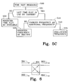
- FIG. 6 is a block diagram illustrating a 180 degrees 3 dB hybrid coupler.
- FIG. 7 is a block diagram illustrating a power amplification arrangement in the first base station.
- FIG. 8 is a flow diagram illustrating a method for dimensioning a power amplifying unit in the first base station.
- FIG. 9 is a diagram illustrating a cummulative distribution function of required output power.
- FIG. 1 illustrates parts of a radio communication system 100 comprising a terrestrial cellular radio communication network 101 , referred to as cellular network 101 in the following, and a set of mobile stations MS 1 -MS 4 .
- cellular network 101 comprises a mobile services switching centre MSC 1 and base stations BS 1 -BS 3 connected to the mobile services switching centre MSC 1 .
- the base stations BS 1 -BS 3 provide radio coverage in a geographical area served by the mobile services switching centre MSC 1 .
- the mobile services switching centre MSC 1 is responsible for switching calls to and from mobile stations MS 1 -MS 4 located in the geographical area served by the mobile services switching centre MSC 1 .
- FIG. 1 only includes elements deemed necessary for illustrating the present invention and that a typical cellular network comprises several mobile services switching centres, a greater number of base stations as well as other types of nodes such as home location registers.
- FIG. 1 illustrates how the geographical area served by the mobile services switching centre MSC 1 is divided into five cells C 1 -C 5 .
- radio coverage is provided by one of the base stations BS 1 -BS 3 respectively.
- the base stations BS 2 and BS 3 provide radio coverage in the cells C 4 and C 5 respectively, i.e.
- the base stations BS 2 and BS 3 provide radio coverage in one cell each, while the base station BS 1 , referred to as the first base station BS 1 in the following, provides radio coverage in the three cells C 1 -C 3 , i.e. the base station BS 1 provides radio coverage in a plurality of cells. Transmissions of radio signals from any one of the base stations BS 1 -BS 3 to the mobile stations MS 1 -MS 4 are said to occur in the downlink direction while transmissions from any one of the mobile stations MS 1 -MS 4 to any one of the base stations BS 1 -BS 3 are said to occur in the uplink direction.
- FIG. 2 illustrates one example of a FCA-scheme in the form of a so called “4/12” cell pattern for frequency reuse.
- the “4/12” cell pattern is applied to the cellular network 101 of FIG. 1 .
- the total frequency band allocated to the cellular network 101 is divided into 12 frequency groups FA 1 -FA 3 , FB 1 -FB 3 , FC 1 -FC 3 and FD 1 -FD 3 .
- Each cell is allocated a frequency group according to the pattern illustrated in FIG. 2, thus e.g. cells C 1 -C 5 are allocated frequency groups FA 1 -FA 3 , FB 2 and FD 1 as illustrated in FIG. 1 .
- Adaptive channel allocation is a method of dynamically allocating frequencies througout a cellular network to maximise network capacity. Under an ACA-scheme, more frequencies would be allocated to busy cells from more lightly loaded cells. In addition, the channels can be allocated such that all links have satisfactory quality.
- ACA-schemes have been proposed such as the schemes proposed in the international patent application WO 97/32444 and the U.S. Pat. No. 5,491,837. It may be noted that there is a distinction between allocation of a frequency for use in a cell, i.e. making the frequency available for use in the cell and actually performing transmission of a radio frequency carrier using the allocated frequency. The two steps of allocating the frequency and actually using the frequency for radio transmission may however occur essentially simultaneously.
- each base station BS 1 -BS 3 in the cellular network 101 is related to the power amplification of radio signals transmitted by the base stations.
- the cost related to power amplification equipment is essentially proportional to the total maximum output power the base station is designed to deliver. Hence, it is important to utilize the available output power in the base station as efficient as possible and strive to minimise the total maximum output power required. Not only the equipment costs but also the power consumption, size and weight will be reduced as a consequence of the base station being designed to deliver less total maximum output power.
- power reducing functions such as power control and discontinuous transmission. (alternatively called voice operated transmission), which when applied to a radio carrier causes a decrease in the average radio carrier signal power.
- voice operated transmission which when applied to a radio carrier causes a decrease in the average radio carrier signal power.
- These power reducing functions have been used to reduce the interference level in a cellular network and improve mobile station operation time by conserving battery power.
- power reducing functions When such power reducing functions are applied to radio carriers transmitted by a base station in the down link direction, they give statistical reductions in the total output power the base station needs to deliver in order to be able to support a certain number of radio carriers. The statistical reductions in the required total output power rely on the observation that if e.g.
- output power is individually set on each time slot on each carrier, it is highly improbable, if there are a sufficient number of radio carriers, that a worst case situation, where all radio carriers simultaneously requires maximum output power, will arise. Due to a very low probability for the worst case scenario, the base station need not be designed to provide enough output power to handle the worst case scenario. Instead the base station can be designed to provide enough output power to ensure that there is an acceptable probability, i.e. a sufficiently low but non-zero probability, for the occurence of situations where the base station cannot provide enough output power.
- FIG. 3 is a diagram illustrating an estimate of the statistical reductions in required total output power PREDI (in dB) as a function of the number N of radio carriers when power control is applied individually to each time slot on each radio carrier in the downlink direction.
- a power amplifier designed to support e.g. 15 radio carriers could be designed to deliver significantly less output power per radio carrier as compared to a power amplifier designed to support e.g. 5 radio carriers.
- the present invention offers a way to further reduce the total maximum output power a base station is required to deliver in situations where there are to few radio carriers in a cell to fully benefit from the use of power reducing functions in the downlink direction.
- Capacity demand in cell C 3 will only be high during office hours.
- the cellular network 101 would be able to adapt the set of frequencies allocated to each of the cells C 1 -C 3 in response to changes in capacity demand in the cells.
- the first base station BS 1 must be able to deliver enough output power in cell C 1 to support downlink transmissions also on the additional frequencies.
- the first base station BS 1 would need to be designed with spare output power capacity in cell C 1 which is very seldom utilized.
- the present invention offers a solution to the problem of enabling the first base station BS 1 to provide enough output power in cell C 1 to support the allocation of additional frequencies to cell C 1 without requiring the first base station BS 1 to be designed with under utilized spare output power capacity in cell C 1 .
- the basic principle of the invention is to use a common set of multi carrier amplifiers to amplify radio signals transmitted by a base station in different cells of a terrestrial cellular network.
- the basic principle of the invention can be applied in different embodiments of the invention to achieve further statistical reductions in required total maximum output power of a base station when downlink power reduction functions are used and/or to avoid the need to design the base station with spare output power capacity in cells to support allocation of additional frequencies using an Adaptive Channel Allocation scheme.
- Using a common set of multi carrier power amplifiers to serve more than one cell instead of individual sets of multi carrier power amplifiers serving each individual cell means that the common set of multi carrier power amplifiers handles an increased number of radio frequency carriers as compared to the number of radio frequency carriers each individual set of multi carrier power amplifiers would have handled.
- the use of the common set of multi carrier power amplifiers in combination with the use of downlink power reduction functions, such as downlink power control or discontinuous transmission causes a reduction in the required total maximum output power of a base station.
- Using a common set of multi carrier power amplifiers to serve more than one cell also enables a base station to distribute varying amounts of the total output power produced by the common set of multi carrier power amplifiers between the different cells. Hence, as long as the total power demand in all cells does not exceed the maximum output power the common set of multi carrier power amplifiers is able to produce, it is possible to distribute output power to a cell in support of additional frequencies allocated to that cell.
- FIG. 4 illustrates more details of the first base station BS 1 and the mobile services switching centre MSC 1 in accordance with the first embodiment of the invention.
- the first base station BS 1 comprises radio signal generating means 401 , a power amplifying unit 402 and an antenna system 403 .
- the radio signal generating means includes a digital base band unit 404 connected to three multi carrier transceivers 405 - 407 .
- the power amplifying unit 402 includes a power sharing network 408 having a plurality of input ports 420 - 423 and output ports 424 - 427 , a common set of multi carrier power amplifiers 409 - 412 each having an input and an output and an inverse power sharing network 413 having a plurality of input ports 428 - 431 and output ports 432 - 435 .
- Each amplifier 409 - 412 is connected with its input port to one of the output ports 424 - 427 of the power sharing network 408 and is connected with its output port to one of the input ports 428 - 431 of the inverse power sharing network 413 .
- the antenna system 403 includes a first antenna 414 , a second antenna 415 and a third antenna 416 .
- the antennas 414 - 416 are each associated with a different one of the three cells C 1 -C 3 and provides an antenna beam 417 - 419 covering the associated cell.
- the first base station BS 1 also comprises one or several control processors (not shown in FIG. 4) controlling the overall operation of the first base station BS 1 and handling communication with the mobile services switching centre MSC 1 .
- the mobile services switching centre MSC 1 comprises one or several control processors 440 executing program instructions stored in one or several memory units 441 .
- the first base station BS 1 and the mobile services switching centre MSC 1 communicate with each other using e.g. an optical fibre or a radio link.
- FIG. 5A illustrates part of the method for transmitting radio signals in the cellular network 101 according to the examplifying first embodiment of the invention.
- a first set of low power radio signals S 11 -S 13 is generated by the radio signal generating means 401 .
- the first set of low power radio signals S 11 -S 13 includes a first radio signal S 11 , a second radio signal S 12 and a third radio signal S 13 .
- the first radio signal S 11 which is associated with the first cell C 1 , is generated so as to consist of radio carrier components having frequencies allocated for use in the first cell C 1 .
- the second radio signal S 12 which is associated with the second cell C 2
- the third radio signal S 13 which is associated with the third cell C 3
- the second radio signal S 12 is generated so as to consist of radio signals having frequencies allocated for use in the second cell C 2
- the third radio signal S 13 which is associated with the third cell C 3
- the base band unit 404 receives instructions from the mobile services switching centre MSC 1 concerning which radio carrier components should be included in each of the three signals S 11 -S 13 and generates three digital base band signals corresponding to said signals S 11 -S 13 .
- the digital signals are passed to the three multi carrier transceivers 405 - 407 which generate the three signals S 11 -S 13 by performing Digital-to-Analog and radio frequency conversion of the corresponding digital base band signal.
- Steps 502 - 504 generate a second set of amplified radio signals S 21 -S 23 corresponding to the first set of radio signals S 11 -S 13 by amplification of the first set of radio signals S 11 -S 13 in the power amplifying unit 402 , i.e. the second set of radio signals S 21 -S 23 consists of amplified versions of each signal in the first set of radio signals S 11 -S 13 .
- a third set of radio signals S 31 -S 34 is provided by the power sharing network 408 on its output ports 424 - 427 .
- the power sharing network 408 receives the first set of radio signals S 11 -S 13 on its input ports 420 - 422 and distributes a portion of each signal in the first set of radio signals S 11 -S 13 to each of its output ports 424 - 427 .
- Each signal in the first set of radio signals S 11 -S 13 is distributed in portions of substantially equal power levels and staggered in phase to each of the output ports 424 - 427 .
- each of the signals S 31 -S 34 in the third set of radio signals will contain an equal portion of e.g. the first radio signal S 11 .
- the portions of the first radio signal S 11 in e.g. signals S 31 and S 32 will however be shifted in phase relative to each other.
- a fourth set of radio signals S 41 -S 44 is provided by amplifying each signal in the third set of radio signals S 31 -S 34 in one of the amplifiers in the common set of multi carrier power amplifiers 409 - 412 .
- the second set of radio signals S 21 -S 23 is provided by the inverse power sharing network 413 on its output ports 432 - 434 .
- the inverse power sharing network 413 performs the inverse operation of the power sharing network 408 on the fourth set of radio signals S 41 -S 44 .
- the inverse power sharing network 413 provides e.g. the signal S 21 , which is the signal in the second set of radio signals which corresponds to the first signal S 1 , by recombining the content of each signal in the third set S 31 -S 34 which originates from the first radio signal S 11 .
- the second set of radio signals S 21 -S 23 corresponding to the first set of radio signals S 11 -S 13 is radiated in the respective associated antenna beam 417 - 419 , i.e. signal S 21 , which is the amplified radio signal corresponding to the first radio signal S 11 , is radiated by the first antenna 414 in its antenna beam 417 , signal S 22 , which is the amplified radio signal corresponding to the second radio signal S 12 , is radiated by the second antenna 415 in its antenna beam 418 and signal S 23 , which is the amplified radio signal corresponding to the third radio signal S 13 , is radiated by the third antenna 414 in its antenna beam 419 .
- FIG. 6 and FIG. 7 gives a detailed example how the power amplification unit 402 in FIG. 4 may be implemented.
- FIG. 6 illustares a 180° 3 dB hybrid coupler 601 . If the input signals to the hybrid coupler 601 are S 61 and S 62 , the output signals S 63 and S 64 are:
- FIG. 7 illustrates how the power sharing network 408 and the inverse power sharing network 413 may be designed as so called Butler matrixes using 180 ° 3 dB hybrid couplers 601 .
- the power sharing network 408 has four input ports 420 - 423 , while only three of these input ports 420 - 422 are used to receive the signals in the first set of radio signals S 11 -S 13 .
- the main reason for designing the power sharing network 408 and the inverse power sharing network 413 as Butler matrixes having four input ports and four output ports, is that Butler matrixes having 2 n input ports and output ports, e.g. 2, 4, 8, or 16 ports, suffers from less losses than Butler matrixes having any other number of ports.
- the power sharing network input port 423 is connected to ground while the inverse power sharing network output port 435 is connected to a monitor 436 .
- the monitor 436 checks that no signal is received on the output port 435 , i.e. that the output port 435 is at ground level. If in fact a signal other than ground is received by the monitor at the output port 435 , this is an indication that there is a malfunction somewhere in the power amplifying unit 402 and the monitor may provide an error indication to operation and maintenance personnel.
- the cellular network 101 applies power control to transmissions in the downlink direction of all cells C 1 -C 5 .
- Applying power control in the downlink direction means that the transmission power for a time slot on a radio carrier in the downlink direction, is adapted to the actual power needed for radio signals to reach a mobile station with sufficient signal strength.
- a Fast Power Control (FPC) bit is specified for use in both the uplink and downlink directions.
- the mobile station measures the received signal quality and requests the first base station to increase or decrease the transmission power by setting the FPC-bit either to 1 or 0 in its transmissions on the corresponding time slot in the uplink direction.
- the first base station BS 1 integrates the received increase/decrease requests in several consecutive FPC-bits to determine whether the downlink transmission power should be adjusted, and hence the mobile station can request the first base station BS 1 to maintain the present output power by transmitting an alternating FPC-bit pattern.
- the first base station BS 1 is designed to benefit from the previously discussed statistical reduction in required output power caused by application of power control in the down link direction.
- the first base station BS 1 may e.g. be designed to support simultaneous transmission of five radio frequency carriers in each of the cells C 1 -C 3 , i.e. the power amplifying unit 402 is designed to deliver a total maximum output power supporting simultaneous transmission of 15 radio frequency carriers.
- An antenna feeder would typically need to be fed with 11 Watt for downlink transmission of a single radio frequency carrier.
- the power amplifying unit would have to be designed to deliver a total maximum output power of about 165 Watt. Due to the use of downlink power control, which for 15 radio frequency carriers causes a statistical reduction in the required output power of about 3.9 dB or about 2.5 times, it is however sufficient that the power amplifying unit 402 is designed to deliver about 66 Watt.
- a base station designed to support simultaneous transmission of five radio frequency carriers in three cells, but having separate power amplifying units for each cell would also have to be designed to deliver a total maximum output power of about 165 Watt if no downlink power reducing functions are used.
- Using downlink power control in each cell would mean a statistical reduction in the required output power of each separate power amplifying unit of only about 2 dB or about 1.6 times and the total maximum output power required would be about 103 Watt.
- FIG. 8 illustrates in more general terms the method according to which the power amplifying unit 402 is dimensioned, i.e. its maximum output power is selected.
- a statistical distribution is determined of the required total output power P REQ of the power amplifying unit 402 for simultaneous transmission of upto a defined maximum number N max of radio frequency carriers in the set of cells C 1 -C 3 for which the power amplifying unit 402 performs power amplification.
- the power amplification unit 402 performs power amplification of all the radio frequency carriers transmitted by the first base station BS 1 in all three cells C 1 -C 3 served by the first base station BS 1 , i.e. the power amplifying unit 402 needs to be able to support a maximum of 15 radio frequency carriers.
- FIG. 9 illustrates a cumulative distribution function 901 of the required total output power P REQ of the power amplifying unit 402 when the first base station BS 1 , using upto 15 radio frequency carriers, is operating under traffic conditions causing a blocking probability of 1%.
- the required total output power PREQ is expressed in terms of how much the total output power is reduced as compared to a total output power corresponding to maximum transmit power on 15 carriers, i.e. 165 Watt. Note that it is only during busy hours that the first base station BS 1 is operating with a blocking probability as high as 1%.
- the power amplifying unit 402 is dimensioned dependent on the statistical distribution determined at step 801 .
- the power amplifying unit 402 is dimensioned for delivering a total maximum output power which provides an acceptable non-zero probability that the power amplifying unit 402 will be incapable of providing enough output power for simultaneous transmission of the defined maximum number of radio frequency carriers.
- a probability of 5% that the power amplifying unit 402 can not provide enough output power when the first base station BS 1 is operating under traffic conditions causing a blocking probability of 1% is considered acceptable and hence, based on the cumulative distribution function 901 in FIG. 9, the power amplifying unit 402 is designed to deliver a total maximum output power of 66 Watt, i.e. 3.9 dB less than 165 Watt.
- the cellular network 101 furthermore employs an Adaptive Channel Allocation scheme allowing the set of frequencies allocated for use in each individual cell C 1 -C 3 to be adapted to changes in capacity demand.
- the channel allocation scheme used in the cellular network 101 in FIG. 1 is based on a fixed channel allocation scheme according to FIG. 2 complemented by the capability of temporarily allocating a borrowed channel for use in a cell requiring additional frequencies to serve the current capacity demand.
- the set of frequencies allocated to a cell comprises a basic set of frequencies allocated according to the basic fixed channel allocation scheme, excluding any frequencies borrowed for use in other cells, and may also comprise a set of additional frequencies borrowed from other cells.
- FIGS. 5B and 5C illustrates the Adaptive Channel Allocation scheme used in the cellular network 101 according to the first exemplifying embodiment of the invention.
- a request for communication in a selected one of the cells C 1 -C 3 is received by the mobile services switching centre MSC 1 .
- the selected cell may e.g. be cell C 1 .
- the mobile services switching centre MSC 1 determines whether the set of frequencies allocated for use in the selected cell C 1 is sufficient to service the request for communication.
- a new frequency is brought into active use.
- a frequency allocated to the cell C 1 but not in active use, is selected, at step 515 the selected frequency is registered as being in active use and at step 516 a time slot on the selected frequency is assigned to service the communication request.
- the mobile services switching centre MSC 1 proceeds at step 517 to determine a candidate set of frequencies allocated for use in the cellular network 101 but which are currently not in active use for communication in the vicinity of the cell C 1 . In the first embodiment of the invention, it is sufficient to include one candidate frequency in the candidate set of frequencies.
- the mobile services switching centre MSC 1 uses configuration data stored in the memory units 441 to determine which cells are in the vicinity of the cell C 1 and examines the registered status of frequencies, i.e. whether they are registered in the memory units 441 as being in active use for communication or inactive, in said cells. Finding a candidate frequency is performed in two steps.
- a potential candidate frequency is identified among the frequencies belonging to the basic set of frequencies allocated to cells immediately adjacent to the cell C 1 and preferrably allocated to one of the other cells C 2 -C 3 served by the first base station (BS 1 ). Then a check is made that the potential candidate frequency is not in active use in any cell within a distance corresponding to the re-use distance, i.e. the distance between two cells allocated the same basic set of frequencies according to the employed “4/12” cell reuse pattern, of cell C 1 . This way it is ensured that no significant additional cochannel interference is introduced in the cellular network 101 when the candidate frequency is temporarily allocated for use in the cell C 1 .
- the mobile services switching centre MSC 1 borrows, i.e. temporarily allocates, the candidate frequency as an additional frequency for use in the cell C 1 .
- the candidate frequency is temporarily deallocated, i.e. marked as unavailable, in cells in the vicinity of cell C 1 .
- the candidate frequency is allocated to cell C 1 , it will not be used for communication in cells in the vicinity of the cell C 1 .
- a time slot on the additional frequency is assigned to service the communication request.
- FIG. 5C illustrates a sequence of steps performed when a communication session is finished.
- a time slot is released.
- a check is made whether the released time slot was the last time slot in use on a radio frequency carrier. If the time slot was not the last time slot (an alternative NO), i.e. the radio frequency carrier is still in active use for communication, the time slot is marked as available at step 532 . If the time slot was indeed determined to be the last time slot at step 531 (an alternative YES), a check is made at step 533 whether the radio carrier frequency is an additional frequency and hence only temporarily assigned to the cell C 1 . If the radio carrier frequency is not an additional frequency (an alternative NO), the radio carrier frequency is registered as being inactive at step 534 .
- the radio carrier frequency is deallocated from cell C 1 at step 535 , i.e. the frequency is once more made available for use in those cells in the vicinity of cell C 1 where the frequency is part of a basic set of frequencies allocated to said cells.
- a check could be made each time a time slot is released whether there is enough capacity within the basic set of frequencies in the cell to handle the ongoing communication sessions and if so, moving communication sessions from the additional frequency to frequencies in the basic set of frequencies and then deallocating the additional frequency.
- the power amplifying unit of the first base station BS 1 could be implemented apart from the specific embodiment disclosed in FIG. 4 and FIG. 7 .
- Examples of other ways of arranging the power amplifying unit can be found in e.g. U.S. Pat. No. 5,854,611 and U.S. Pat. No. 4,618,813.
- the first and second set of radio signal's would include not only one but several radio signals associated with each respective cell. There would be one low power radio signal in the first set of radio signals and a corresponding amplified radio signal in the second set of radio signals for each narrow antenna beam.
- the first base station BS 1 could be adapted to serve only two cells or more than three cells. Furthermore, the first base station BS 1 could be adapted to serve cells arranged in an hierarchical cell structure e.g. by serving an additional umbrella cell providing radio coverage in an area overlapping at least one of the cells C 1 -C 3 .
- the mobile services switching centre MSC 1 and more specifically the control processors 440 and the memory units 441 perform a multitude of different tasks and in particular act as:
- control means for controlling the set of radio carrier componenets included by the radio signal generating means 401 in each signal in the first set of radio signals S 11 -S 13 ;
- adaptive means for adapting the set of frequencies allocated for use in the cells C 1 -C 3 ;
- registering means for registering which frequencies are currently in active use for communication.
- BSC base station controller
- RNC radio network controller
- the power amplifying unit 402 whenever the required output power from the power amplifying unit 402 in a time slot exceeds the power amplifying capacity of the power amplifying unit 402 , the power amplifying unit 402 will be incapable of providing enough output power for transmission of bursts on all active radio frequency carriers in the time slot.
- One way of handling occurences of situations where the power amplifying unit 402 is unable to deliver enough output power, is to refrain from transmitting bursts on one or several active radio frequency carriers so as to ensure that the power amplifying capacity of the power amplifying unit 402 is not exceeded.
- the carriers on which no bursts are transmitted can e.g. be selected randomly.
- Another way of handling these situations is to transmit bursts on all active radio frequency carriers but with reduced power on one or several radio frequency carriers so as to ensure that the power amplifying capacity of the power amplifying unit 402 is not exceeded.
- the transmit power on all active radio frequency carriers can be reduced equally much. If reducing the transmit power on all active radio frequency carriers enables the transmit power on some of the radio frequency carriers to be increased, the transmit power of the carriers with the lowest transmit power is increased first. Alternatively, instead of reducing the transmit power of all active radio carrier frequencies, the transmit power of the strongest radio carrier frequencies can be reduced first.
- the Adaptive Channel Allocation scheme used in the first embodiment of the invention is but one example of a multitude of different ACA-schemes which can be used in the context of the present invention.
- the selection can be based on measurements in the selected cell of interference levels on frequencies currently not allocated to the selected cell.
- the additional frequency selected for allocation to the cell is a measured frequency which is determined to experience interference below a predetermined level. Measurements can be initiated upon receipt of a request for communication in the selected cell when detecting that the set of frequencies allocated for use in the selected cell is insufficient to service the request for communication.
- interference level measurements are preferrably performed continuously. The measurements can be performed by a scanning receiver in the base station serving the selected cell as suggested in the published international patent application WO 97/32444.
- application of the invention is in no way limited to only terrestrial cellular radio communication networks conforming to the EIA/TIA IS-136 specifications.
- the invention is also applicable in cellular networks adhering to e.g. the GSM-, PDC, AMPS, TACS, NMT, or IS-95 specifications and evolutions of these specifications such as EDGE or GPRS.
Landscapes
- Engineering & Computer Science (AREA)
- Computer Networks & Wireless Communication (AREA)
- Signal Processing (AREA)
- Power Engineering (AREA)
- Mobile Radio Communication Systems (AREA)
- Transmitters (AREA)
- Radar Systems Or Details Thereof (AREA)
Applications Claiming Priority (2)
| Application Number | Priority Date | Filing Date | Title |
|---|---|---|---|
| SE9902984 | 1999-08-24 | ||
| SE9902984A SE9902984L (sv) | 1999-08-24 | 1999-08-24 | Förfarande och anordning relaterande till ett radiokommunikationsnät |
Publications (1)
| Publication Number | Publication Date |
|---|---|
| US6650876B1 true US6650876B1 (en) | 2003-11-18 |
Family
ID=20416731
Family Applications (1)
| Application Number | Title | Priority Date | Filing Date |
|---|---|---|---|
| US09/636,328 Expired - Lifetime US6650876B1 (en) | 1999-08-24 | 2000-08-10 | Methods and arrangement relating to a radio communication network |
Country Status (9)
| Country | Link |
|---|---|
| US (1) | US6650876B1 (enExample) |
| EP (1) | EP1206847B1 (enExample) |
| JP (1) | JP2003507956A (enExample) |
| CN (1) | CN1242565C (enExample) |
| AT (1) | ATE363772T1 (enExample) |
| AU (1) | AU6042200A (enExample) |
| DE (1) | DE60035051T2 (enExample) |
| SE (1) | SE9902984L (enExample) |
| WO (1) | WO2001015335A1 (enExample) |
Cited By (10)
| Publication number | Priority date | Publication date | Assignee | Title |
|---|---|---|---|---|
| US20030119541A1 (en) * | 2000-08-29 | 2003-06-26 | Hiromitsu Ubuki | Base station device, control station device, and transmission power control method |
| US20040018843A1 (en) * | 1999-02-22 | 2004-01-29 | Telefonaktiebolaget Lm Ericsson | Mobile radio system and a method for channel allocation in a mobile radio system |
| US20050043858A1 (en) * | 2002-07-16 | 2005-02-24 | Alexander Gelman | Atomic self-healing architecture |
| US20070072645A1 (en) * | 2005-09-29 | 2007-03-29 | Clark Andrew C | Capacity allocation in a wireless communication system |
| WO2007099078A1 (de) * | 2006-03-01 | 2007-09-07 | Nokia Siemens Networks Gmbh & Co. Kg | Anordnung zur sendeleistungserhöhung |
| US20120003942A1 (en) * | 2010-07-01 | 2012-01-05 | Norbert Grunert | Method and system for signal strength measurement |
| US8676264B2 (en) | 2009-07-28 | 2014-03-18 | Huawei Technologies Co., Ltd. | Method and apparatus for power sharing among multi-carrier modules of a multi-carrier base station |
| US20150256134A1 (en) * | 2014-03-04 | 2015-09-10 | Eutelsat Sa | Method for detecting an unbalance and for calibrating a multi-port amplifier of a telecommunications satellite |
| US9253741B2 (en) | 2011-06-17 | 2016-02-02 | Hitachi Kokusai Electric Inc. | Wireless communication system, terminal device, and base station device |
| US10454567B2 (en) | 2016-03-02 | 2019-10-22 | Mitsubishi Electric Corporation | Multi-beam satellite communication system |
Families Citing this family (7)
| Publication number | Priority date | Publication date | Assignee | Title |
|---|---|---|---|---|
| US7110727B2 (en) | 2001-04-17 | 2006-09-19 | Nokia Corporation | Methods for determining the gains of different carriers, radio transmission units and modules for such units |
| CN100334826C (zh) * | 2001-04-17 | 2007-08-29 | 诺基亚公司 | 确定不同载波增益的方法、无线发射装置及用于其的模块 |
| US7411930B2 (en) * | 2003-12-17 | 2008-08-12 | Qualcomm, Incorporated | Apparatus and method for prioritized apportionment of transmission power in a multi-carrier terminal |
| KR100735316B1 (ko) | 2005-06-29 | 2007-07-04 | 삼성전자주식회사 | 통신 시스템에서 신호 송신 시스템 및 방법 |
| FR2891421B1 (fr) * | 2005-09-23 | 2007-11-23 | Alcatel Sa | Dispositif d'emission et/ou reception de signaux a reutilisation de frequence par affectation d'une cellule par terminal, pour un satellite de communication |
| EP2346175B1 (en) * | 2010-01-15 | 2015-03-11 | Telefonaktiebolaget L M Ericsson | A method and apparatuses for transmitter to multi-carrier power amplifier configuration |
| WO2012060750A1 (en) * | 2010-11-04 | 2012-05-10 | Telefonaktiebolaget L M Ericsson (Publ) | Method and arrangement for power sharing in a base station |
Citations (13)
| Publication number | Priority date | Publication date | Assignee | Title |
|---|---|---|---|---|
| US4618831A (en) | 1984-09-25 | 1986-10-21 | Nippon Telegraph & Telephone Corporation | Power amplifying apparatus |
| US5491837A (en) | 1994-03-07 | 1996-02-13 | Ericsson Inc. | Method and system for channel allocation using power control and mobile-assisted handover measurements |
| US5610617A (en) * | 1995-07-18 | 1997-03-11 | Lucent Technologies Inc. | Directive beam selectivity for high speed wireless communication networks |
| US5646631A (en) * | 1995-12-15 | 1997-07-08 | Lucent Technologies Inc. | Peak power reduction in power sharing amplifier networks |
| EP0786826A2 (en) | 1996-01-29 | 1997-07-30 | He Holdings, Inc. Dba Hughes Electronics | Intermodulation scattering communications apparatus |
| WO1997032444A1 (en) | 1996-02-29 | 1997-09-04 | Telefonaktiebolaget Lm Ericsson (Publ) | Adaptive frequency allocation in a telecommunication system |
| WO1997041704A1 (en) | 1996-04-29 | 1997-11-06 | Radio Design Innovation Ab | Method and arrangement of converting a cellular telecommunication system |
| US5726978A (en) * | 1995-06-22 | 1998-03-10 | Telefonaktiebolaget L M Ericsson Publ. | Adaptive channel allocation in a frequency division multiplexed system |
| US5764104A (en) | 1996-05-31 | 1998-06-09 | Motorola, Inc. | Method and system for reducing noise in a hybrid matrix amplifier |
| US5809423A (en) * | 1995-03-09 | 1998-09-15 | Lucent Technologies, Inc. | Adaptive-Dynamic channel assignment organization system and method |
| US5854611A (en) | 1995-07-24 | 1998-12-29 | Lucent Technologies Inc. | Power shared linear amplifier network |
| US5987037A (en) * | 1996-02-26 | 1999-11-16 | Lucent Technologies Inc. | Multiple beam wireless telecommunication system |
| US6091934A (en) * | 1997-09-02 | 2000-07-18 | Hughes Electronics Corporation | Dynamic power allocation system and method for multi-beam satellite amplifiers |
Family Cites Families (3)
| Publication number | Priority date | Publication date | Assignee | Title |
|---|---|---|---|---|
| JPS60119103A (ja) * | 1983-11-30 | 1985-06-26 | Mitsubishi Electric Corp | 送信空中線装置 |
| TW280064B (enExample) * | 1994-09-29 | 1996-07-01 | Radio Frequency Systems Inc | |
| US5834972A (en) * | 1996-10-11 | 1998-11-10 | Motorola, Inc. | Method and system in a hybrid matrix amplifier for configuring a digital transformer |
-
1999
- 1999-08-24 SE SE9902984A patent/SE9902984L/ not_active IP Right Cessation
-
2000
- 2000-07-04 AU AU60422/00A patent/AU6042200A/en not_active Abandoned
- 2000-07-04 AT AT00946706T patent/ATE363772T1/de not_active IP Right Cessation
- 2000-07-04 EP EP00946706A patent/EP1206847B1/en not_active Expired - Lifetime
- 2000-07-04 DE DE60035051T patent/DE60035051T2/de not_active Expired - Lifetime
- 2000-07-04 WO PCT/SE2000/001422 patent/WO2001015335A1/en not_active Ceased
- 2000-07-04 JP JP2001518943A patent/JP2003507956A/ja active Pending
- 2000-07-04 CN CNB008119759A patent/CN1242565C/zh not_active Expired - Fee Related
- 2000-08-10 US US09/636,328 patent/US6650876B1/en not_active Expired - Lifetime
Patent Citations (14)
| Publication number | Priority date | Publication date | Assignee | Title |
|---|---|---|---|---|
| US4618831B1 (en) | 1984-09-25 | 1997-01-07 | Nippon Telegraph & Telephone | Power amplifying apparatus |
| US4618831A (en) | 1984-09-25 | 1986-10-21 | Nippon Telegraph & Telephone Corporation | Power amplifying apparatus |
| US5491837A (en) | 1994-03-07 | 1996-02-13 | Ericsson Inc. | Method and system for channel allocation using power control and mobile-assisted handover measurements |
| US5809423A (en) * | 1995-03-09 | 1998-09-15 | Lucent Technologies, Inc. | Adaptive-Dynamic channel assignment organization system and method |
| US5726978A (en) * | 1995-06-22 | 1998-03-10 | Telefonaktiebolaget L M Ericsson Publ. | Adaptive channel allocation in a frequency division multiplexed system |
| US5610617A (en) * | 1995-07-18 | 1997-03-11 | Lucent Technologies Inc. | Directive beam selectivity for high speed wireless communication networks |
| US5854611A (en) | 1995-07-24 | 1998-12-29 | Lucent Technologies Inc. | Power shared linear amplifier network |
| US5646631A (en) * | 1995-12-15 | 1997-07-08 | Lucent Technologies Inc. | Peak power reduction in power sharing amplifier networks |
| EP0786826A2 (en) | 1996-01-29 | 1997-07-30 | He Holdings, Inc. Dba Hughes Electronics | Intermodulation scattering communications apparatus |
| US5987037A (en) * | 1996-02-26 | 1999-11-16 | Lucent Technologies Inc. | Multiple beam wireless telecommunication system |
| WO1997032444A1 (en) | 1996-02-29 | 1997-09-04 | Telefonaktiebolaget Lm Ericsson (Publ) | Adaptive frequency allocation in a telecommunication system |
| WO1997041704A1 (en) | 1996-04-29 | 1997-11-06 | Radio Design Innovation Ab | Method and arrangement of converting a cellular telecommunication system |
| US5764104A (en) | 1996-05-31 | 1998-06-09 | Motorola, Inc. | Method and system for reducing noise in a hybrid matrix amplifier |
| US6091934A (en) * | 1997-09-02 | 2000-07-18 | Hughes Electronics Corporation | Dynamic power allocation system and method for multi-beam satellite amplifiers |
Non-Patent Citations (2)
| Title |
|---|
| Blomqvist, F.; International-Type Search Report, Search Request No. SE99/01113, Jun. 21, 2000, pp. 1-4. |
| Kennington, P.B., et al.; "A Multi-Carrier Amplifier for Future Mobile Communications Systems," Sixth International Conference on Mobile Radio and Personal Communications, 199 pp. 151-156. |
Cited By (17)
| Publication number | Priority date | Publication date | Assignee | Title |
|---|---|---|---|---|
| US20040018843A1 (en) * | 1999-02-22 | 2004-01-29 | Telefonaktiebolaget Lm Ericsson | Mobile radio system and a method for channel allocation in a mobile radio system |
| US6868277B1 (en) * | 1999-02-22 | 2005-03-15 | Telefonaktiebolaget Lm Ericsson | Mobile radio system and a method for channel allocation in a radio system |
| US7130635B2 (en) * | 1999-02-22 | 2006-10-31 | Telefonaktiebolaget Lm Ericsson (Publ) | Mobile radio system and a method for channel allocation in a mobile radio system |
| US20030119541A1 (en) * | 2000-08-29 | 2003-06-26 | Hiromitsu Ubuki | Base station device, control station device, and transmission power control method |
| US7054655B2 (en) * | 2000-08-29 | 2006-05-30 | Matsushita Electric Industrial Co., Ltd. | Base station device, control station device, and transmission power control method |
| US20050043858A1 (en) * | 2002-07-16 | 2005-02-24 | Alexander Gelman | Atomic self-healing architecture |
| US9236770B2 (en) * | 2002-07-16 | 2016-01-12 | Stmicroelectronics, Inc. | Atomic self-healing architecture in an electric power network |
| US7477902B2 (en) * | 2005-09-29 | 2009-01-13 | Alcatel-Lucent Usa Inc. | Capacity allocation in a wireless communication system |
| US20070072645A1 (en) * | 2005-09-29 | 2007-03-29 | Clark Andrew C | Capacity allocation in a wireless communication system |
| WO2007099078A1 (de) * | 2006-03-01 | 2007-09-07 | Nokia Siemens Networks Gmbh & Co. Kg | Anordnung zur sendeleistungserhöhung |
| US8676264B2 (en) | 2009-07-28 | 2014-03-18 | Huawei Technologies Co., Ltd. | Method and apparatus for power sharing among multi-carrier modules of a multi-carrier base station |
| US20120003942A1 (en) * | 2010-07-01 | 2012-01-05 | Norbert Grunert | Method and system for signal strength measurement |
| US8457561B2 (en) * | 2010-07-01 | 2013-06-04 | Broadcom Corporation | Method and system for signal strength measurement |
| US9253741B2 (en) | 2011-06-17 | 2016-02-02 | Hitachi Kokusai Electric Inc. | Wireless communication system, terminal device, and base station device |
| US20150256134A1 (en) * | 2014-03-04 | 2015-09-10 | Eutelsat Sa | Method for detecting an unbalance and for calibrating a multi-port amplifier of a telecommunications satellite |
| US9641135B2 (en) * | 2014-03-04 | 2017-05-02 | Eutelsat S A | Method for detecting an unbalance and for calibrating a multi-port amplifier of a telecommunications satellite |
| US10454567B2 (en) | 2016-03-02 | 2019-10-22 | Mitsubishi Electric Corporation | Multi-beam satellite communication system |
Also Published As
| Publication number | Publication date |
|---|---|
| AU6042200A (en) | 2001-03-19 |
| DE60035051T2 (de) | 2008-01-24 |
| EP1206847B1 (en) | 2007-05-30 |
| CN1242565C (zh) | 2006-02-15 |
| CN1371556A (zh) | 2002-09-25 |
| ATE363772T1 (de) | 2007-06-15 |
| WO2001015335A1 (en) | 2001-03-01 |
| SE9902984L (sv) | 2001-02-25 |
| EP1206847A1 (en) | 2002-05-22 |
| DE60035051D1 (de) | 2007-07-12 |
| SE9902984D0 (sv) | 1999-08-24 |
| JP2003507956A (ja) | 2003-02-25 |
Similar Documents
| Publication | Publication Date | Title |
|---|---|---|
| US6650876B1 (en) | Methods and arrangement relating to a radio communication network | |
| JP2974981B2 (ja) | サテライトをベースとするテレコミュニケーションシステムのためのパワーコントロール方法及び装置 | |
| US5966094A (en) | Base station antenna arrangement | |
| US6246674B1 (en) | Antenna deployment sector cell shaping system and method | |
| JP3936420B2 (ja) | セルラー再利用分割を用いた隣接チャンネル干渉の処理装置及び方法 | |
| US6259922B1 (en) | Managing interference in channelized cellular systems | |
| EP0932946B1 (en) | Method for improving co-channel interference in a cellular system | |
| CN100542345C (zh) | 操作时分双工/虚拟频分双工分级蜂窝电信系统的方法 | |
| US6804214B1 (en) | System and method for implementing multiple carriers in cellular networks | |
| US6167036A (en) | Method and apparatus for a sectored cell of a cellular radio communications system | |
| US5734983A (en) | Frequency assignment in a cellular radio system | |
| US20120202416A1 (en) | Multi-Hop Load Balancing | |
| US6788943B1 (en) | Channel allocation in the base stations of a cellular radio system | |
| EP1799000B1 (en) | Dynamic cell reconfiguring method and cellular network system | |
| JPH03145227A (ja) | 移動通信システムにおいてコール・セットアップまたはハンドオーバ時に基地局、無線チャネル及びタイム・スロットを移動局で選択する方法 | |
| CN100490572C (zh) | 蜂窝无线网络的动态覆盖范围和容量的解决方案 | |
| JP2878456B2 (ja) | セルラ無線システム | |
| US6128497A (en) | High capacity cell planning based on fractional frequency reuse | |
| CN117560769A (zh) | 一种卫星通信星载基站波束管理的方法 | |
| US7200407B1 (en) | Multiple reuse patterns for channels of wireless networks | |
| US6370383B1 (en) | Adaptive power level tiered cellular mobile communications systems | |
| US6334058B1 (en) | Method and apparatus for radio power allocation to a channel during channel assignment based on current system conditions | |
| US5970411A (en) | N=4 directional frequency assignment in a cellular radio system | |
| US20050288032A1 (en) | Resource allocation system and method | |
| SE516365C2 (en) | Terrestrial cellular radio communication network has controllers that instruct radio signal generator to generate radio signal consists of radio carrier components with frequencies allocated for use in cell |
Legal Events
| Date | Code | Title | Description |
|---|---|---|---|
| AS | Assignment |
Owner name: TELEFONAKTIEBOLAGET LM ERICSSON (PUBL), SWEDEN Free format text: ASSIGNMENT OF ASSIGNORS INTEREST;ASSIGNOR:UTTERBORN, CEYLON;REEL/FRAME:011359/0124 Effective date: 20000808 Owner name: TELEFONAKTIEBOLAGET LM ERICSSON (PUBL), SWEDEN Free format text: ASSIGNMENT OF ASSIGNORS INTEREST;ASSIGNOR:STOLT, TOMAS;REEL/FRAME:011359/0136 Effective date: 20000808 Owner name: TELEFONAKTIEBOLAGET LM ERICSSON (PUBL), SWEDEN Free format text: ASSIGNMENT OF ASSIGNORS INTEREST;ASSIGNOR:OSTMAN, THOMAS;REEL/FRAME:011364/0874 Effective date: 20000808 |
|
| STCF | Information on status: patent grant |
Free format text: PATENTED CASE |
|
| FPAY | Fee payment |
Year of fee payment: 4 |
|
| FPAY | Fee payment |
Year of fee payment: 8 |
|
| FPAY | Fee payment |
Year of fee payment: 12 |