US6589212B1 - Guide for surgical device - Google Patents
Guide for surgical device Download PDFInfo
- Publication number
- US6589212B1 US6589212B1 US09/436,118 US43611899A US6589212B1 US 6589212 B1 US6589212 B1 US 6589212B1 US 43611899 A US43611899 A US 43611899A US 6589212 B1 US6589212 B1 US 6589212B1
- Authority
- US
- United States
- Prior art keywords
- guide
- shaft
- tip
- outer diameter
- assembly
- Prior art date
- Legal status (The legal status is an assumption and is not a legal conclusion. Google has not performed a legal analysis and makes no representation as to the accuracy of the status listed.)
- Expired - Lifetime
Links
Images


Classifications
-
- A—HUMAN NECESSITIES
- A61—MEDICAL OR VETERINARY SCIENCE; HYGIENE
- A61M—DEVICES FOR INTRODUCING MEDIA INTO, OR ONTO, THE BODY; DEVICES FOR TRANSDUCING BODY MEDIA OR FOR TAKING MEDIA FROM THE BODY; DEVICES FOR PRODUCING OR ENDING SLEEP OR STUPOR
- A61M25/00—Catheters; Hollow probes
- A61M25/01—Introducing, guiding, advancing, emplacing or holding catheters
- A61M25/06—Body-piercing guide needles or the like
- A61M25/0662—Guide tubes
- A61M25/0668—Guide tubes splittable, tear apart
-
- A—HUMAN NECESSITIES
- A61—MEDICAL OR VETERINARY SCIENCE; HYGIENE
- A61B—DIAGNOSIS; SURGERY; IDENTIFICATION
- A61B17/00—Surgical instruments, devices or methods, e.g. tourniquets
- A61B17/34—Trocars; Puncturing needles
- A61B17/3417—Details of tips or shafts, e.g. grooves, expandable, bendable; Multiple coaxial sliding cannulas, e.g. for dilating
- A61B17/3421—Cannulas
- A61B17/3439—Cannulas with means for changing the inner diameter of the cannula, e.g. expandable
-
- A—HUMAN NECESSITIES
- A61—MEDICAL OR VETERINARY SCIENCE; HYGIENE
- A61M—DEVICES FOR INTRODUCING MEDIA INTO, OR ONTO, THE BODY; DEVICES FOR TRANSDUCING BODY MEDIA OR FOR TAKING MEDIA FROM THE BODY; DEVICES FOR PRODUCING OR ENDING SLEEP OR STUPOR
- A61M25/00—Catheters; Hollow probes
- A61M25/0017—Catheters; Hollow probes specially adapted for long-term hygiene care, e.g. urethral or indwelling catheters to prevent infections
-
- A—HUMAN NECESSITIES
- A61—MEDICAL OR VETERINARY SCIENCE; HYGIENE
- A61B—DIAGNOSIS; SURGERY; IDENTIFICATION
- A61B17/00—Surgical instruments, devices or methods, e.g. tourniquets
- A61B17/34—Trocars; Puncturing needles
- A61B17/3415—Trocars; Puncturing needles for introducing tubes or catheters, e.g. gastrostomy tubes, drain catheters
-
- A—HUMAN NECESSITIES
- A61—MEDICAL OR VETERINARY SCIENCE; HYGIENE
- A61B—DIAGNOSIS; SURGERY; IDENTIFICATION
- A61B17/00—Surgical instruments, devices or methods, e.g. tourniquets
- A61B2017/00831—Material properties
- A61B2017/00867—Material properties shape memory effect
-
- A—HUMAN NECESSITIES
- A61—MEDICAL OR VETERINARY SCIENCE; HYGIENE
- A61M—DEVICES FOR INTRODUCING MEDIA INTO, OR ONTO, THE BODY; DEVICES FOR TRANSDUCING BODY MEDIA OR FOR TAKING MEDIA FROM THE BODY; DEVICES FOR PRODUCING OR ENDING SLEEP OR STUPOR
- A61M25/00—Catheters; Hollow probes
- A61M25/01—Introducing, guiding, advancing, emplacing or holding catheters
- A61M25/02—Holding devices, e.g. on the body
- A61M25/04—Holding devices, e.g. on the body in the body, e.g. expansible
-
- A—HUMAN NECESSITIES
- A61—MEDICAL OR VETERINARY SCIENCE; HYGIENE
- A61M—DEVICES FOR INTRODUCING MEDIA INTO, OR ONTO, THE BODY; DEVICES FOR TRANSDUCING BODY MEDIA OR FOR TAKING MEDIA FROM THE BODY; DEVICES FOR PRODUCING OR ENDING SLEEP OR STUPOR
- A61M25/00—Catheters; Hollow probes
- A61M25/01—Introducing, guiding, advancing, emplacing or holding catheters
- A61M25/06—Body-piercing guide needles or the like
- A61M25/0606—"Over-the-needle" catheter assemblies, e.g. I.V. catheters
Definitions
- This invention relates to a surgical implement guide and more particularly to a flexible guide used to percutaneously introduce a surgical instrument, including a cannula and a trocar, into or through various tissue.
- Peritoneal dialysis is a procedure in which a sterile glucose and salt solution is placed into the peritoneal cavity. The solution plus impurities are removed from the blood at some later time and fresh fluid is reinfused or the cycle can repeat itself. Peritoneal dialysis is effective for treatment of kidney failure and has been used for more than 30 years for this purpose.
- the Tenckhoff catheter developed in the mid 1960's.
- This catheter is a silicon rubber tube with numerous drainage holes on its inner portion.
- the catheter has two polyester (e.g. Dacron R ) “cuffs” which are respectively placed in the subcutaneous tissue and the muscle layer of the patient. These cuffs serve to limit peritoneal leakage, minimize infection and enclose the catheter in the body. The issue arises in the placement of the catheter.
- insertion of catheters into blood vessels is frequently accomplished percutaneously, where a needle with a guide wire is used to initially enter the vessel, rather than use a surgical cut-down procedure.
- Early procedures used the puncture needle itself as the direct conduit into the abdomen or a blood vessel for a catheter of sufficiently small diameter.
- Subsequent art first developed metal sheaths and/or trocars that were formed with a slot, or were split into two distinct pieces for subsequent removal. Rapid development in the art substituted thin-walled plastic sheaths, or other suitable material, for the metal sheaths.
- the most common such prior art sheath is generally known as a “split sheath”. It consists of a cylindrical sheath which, at the distal end is formed to taper to a small diameter opening to permit insertion of a guide wire.
- the opposing proximal end typically has two handles or finger stops formed on opposing sides of the sheath. Score marks are formed along the full length of the sheath and are designed to cause the guide to split apart when the handles are pulled, facilitating the removal of the guide from the body.
- the process of implanting a catheter with this type of split sheath is called the Seldinger Technique. Specifically, in this technique a needle is inserted into a blood vessel. A stainless steel braided wire is then inserted through the needle into the blood vessel, and then the needle is retracted.
- the catheter is inserted into the sheath and the opposite or trailing edge of the wire is inserted into the distal opening of the sheath.
- the wire is pushed through the distal end of the catheter and out the proximal end.
- the sheath with the catheter is pushed into the blood vessel, using the wire as a guide.
- the cone-shaped end of the guide/sheath enters the vessel wall so that the main body of the sheath can be inserted into the blood vessel.
- the wire is removed by pulling it out through the sheath tip.
- sheath becomes covered in fluid, making it difficult to grasp.
- both hands must be employed to remove the sheath, leaving the catheter unattended, unless an assistant is present.
- pulling on the sheath caused it to tear prematurely.
- Another example of a split sheath is disclosed in Y.TEC's Peritoneoscopic Placement of Peritoneal Dialysis Catheters. This sheath attempts to solve some of the disadvantages of the prior art, displaying a guide with a tip and a substantially flat tab. The tab is substantially flat and smooth and can be difficult to grab when it becomes covered in fluid. Again, both hands must be employed, or some other device, such as a hemostat, must be used.
- the present invention provides a device which overcomes the above discussed problems using a surgical implement guide sized for insertion into tissue.
- the guide includes a shaft formed of a flexible material with memory to return to a predetermined configuration, or with ability to have a new or different memory set into it, an opening and passage way of infinitely adjustable dimensions between a predetermined minimum and maximum dimension extendable through the entire length of the shaft and an elongated tab member having at least one textured surface extending from the shaft that acts as a handle for placing, removing or controlling the guide.
- the present invention comprises a surgical implement guide sized for insertion into tissue and a surgical assembly employing the guide.
- the guide includes a shaft formed of a flexible material with memory to return to its predetermined configuration.
- the shaft is adapted to receive a catheter in a chamber defined in the shaft.
- the shaft includes an elongated tab member, preferably a tab integral with the shaft, extending from the shaft that is used as a handle to both place, control and remove the guide.
- the guide further includes an opening and passageway of adjustable dimensions as well as a tip portion for the shaft.
- the tip is integral with the shaft.
- the passageway preferably extends axially the entire length of the shaft, although some lesser distance can be utilized depending on the application as long as it allows for removal of the catheter.
- the tip is situated opposite the elongated tab member. The tip configuration can vary and is selected to assist in the insertion of the guide.
- the guide may have many different forms to accommodate different surgical instruments, surgical procedures, patients or surgeons.
- the tab member can be integral with the shaft or joined thereto, and have a width substantially equal to or less than an outer circumference of the shaft.
- the tab can be substantially flat, curved or pointed in relation to the shaft and rectangular, angled or curved in shape.
- the guide and the tab can have at least one smooth surface and one textured surface, or portion thereof, or two textured surfaces or portions thereof.
- the tip and shaft configurations can vary depending on the application.
- the tip can have an outer diameter substantially equal to or less than the outer diameter of the shaft, so that the tip is pointed, blunted, round, angled or even curved in some fashion.
- the shaft's outer diameter can be substantially the same over its entire length, so that it is substantially cylindrical in shape, or it can vary over the length of the shaft so that it is substantially conical or truncated in shape.
- FIG. 1 is a top plan view of a surgical implement guide in accordance with the present invention
- FIG. 2 is a side elevational view of the surgical implement guide of FIG. 1;
- FIG. 3 is an end view of the surgical implement guide of FIG. 1;
- FIG. 4 is an end view of the surgical implement guide of FIG. 2;
- FIG. 5 is a cross-sectional view of the surgical implement guide of FIG. 1 taken substantially along line 5 — 5 ;
- FIG. 6 is a side elevational view of a first alternate embodiment of the surgical implement guide of FIG. 1;
- FIG. 7 is a top plan view of the surgical implement guide of FIG. 6;
- FIG. 8 is a top plan view of second alternate embodiment of the surgical implement guide of FIG. 1;
- FIG. 9 is a side elevational view of the second alternate embodiment of the surgical implement guide of FIG. 8;
- FIG. 10 is a top plan view of third alternate embodiment of the surgical implement guide of FIG. 1;
- FIG. 11 is a side elevational view of the third alternate embodiment of the surgical implement guide of FIG. 10;
- FIG. 12 is a top plan view of fourth alternate embodiment of the surgical implement guide of FIG. 1;
- FIG. 13 is a side elevational view of the fourth alternate embodiment of the surgical implement guide of FIG. 12;
- FIG. 14 is a side elevational view of fifth alternate embodiment of the surgical implement guide of FIG. 1;
- FIG. 15 is a bottom plan view of the fifth alternate embodiment of the surgical implement guide of FIG. 14;
- FIG. 16 is a perspective view of the surgical implement assembly including the trocar in accordance with the present invention.
- FIG. 17 is an exploded view of the assembly of FIG. 16 depicting the guide and trocar with the obturator removed from the cannula;
- FIG. 18 is a perspective view of the scope used with the cannula
- FIG. 19 is an enlarged partial view of the tip of the guide, with the tip turned in towards the chamber;
- FIG. 20 is an enlarged partial view of the tip of the guide, with the tip secured by the trocar;
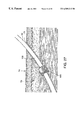
- FIG. 21 a schematic representation of the assembly of FIG. 16 being used on a patient
- FIG. 22 is a schematic representation of the guide implanted in the patient.
- FIG. 23 is a schematic representation of the dilator used with the guide
- FIG. 24 is an enlarged partial view of the dilator and guide of FIG. 23;
- FIG. 25 is a schematic representation of the flexible catheter inserted through the guide of FIG. 16;
- FIG. 26 is an enlarged partial view of the flexible catheter and guide of FIG. 25.
- FIG. 27 is a schematic representation of the final implanted position of the flexible catheter of FIGS. 25 and 26 .
- guide 10 includes an elongated shaft 12 formed of a flexible material with memory to return to an original configuration. Any suitable material, such as biocompatible polyurethane, is contemplated.
- shaft 12 is comprised of polypropylene or other similar material, and may either be clear, opaque or tinted.
- guide 10 could be of any length, however it is preferred that guide 10 be between about 4 inches and about 24 inches long, where shaft 12 is preferably between about 1 inch and about 22 inches in length.
- Shaft 12 is shown with an outer surface 14 and opposed proximal and distal ends 16 and 18 , where it is contemplated that proximal end 16 is straight or flared, and where shaft 12 is adapted to receive a catheter (not shown) or other suitable device in a passageway defined therein (best illustrated in FIG. 5 ).
- shaft 12 is formed of a flexible material allowing opposing sides 24 of shaft 12 to slidably pass one over the other so that the guide 10 may be “rolled” into a diameter slightly smaller than its normal diameter prior to insertion into tissue.
- guide 10 is formed of a material with memory to return to its original configuration, guide 10 will be biased to return to its original shape.
- slot 20 are adjustable depending on the length of the shaft 12 , so that slot 20 is extendable through the entire length thereof.
- slot 20 axially extends from proximal end 16 to distal end 20 as shown in FIG. 1, providing for easy insertion and removal of the catheter.
- slot 20 may not extend the entire length of the shaft 12 , but extend some lesser distance.
- end 16 can be straight or flared to accommodate and/or encapsulate the catheter.
- shaft 12 can have more than one slot 20 , preferably parallel to each other, although other arrangements are contemplated, which are used to position the guide 10 , place the catheter, or position tools used to place the catheter.
- An elongated tab member 26 extends from proximal end 16 of shaft 12 , where the elongated member 26 acts as a tab or handle, providing a sure grip for the user during insertion or withdrawal of the guide 10 , or removal of the catheter therefrom.
- elongated member 26 is a tab 28 joined to shaft 12 at proximal end 16 , in one preferred embodiment, tab 28 is formed integral with shaft 12 .
- FIG. 1 illustrates a tab 28 which is substantially rectangular in shape, having proximal and distal ends 30 and 32 respectively, where distal end 32 is connected to, and preferably integral with, proximal end 16 . While a rectangular embodiment is depicted for tab 28 , many shapes are contemplated, including an angled or curved tab. Tab 28 could further be formed with a blunt proximal end 30 suitable to push the guide 10 into the tissue, or tab 28 could be flared to accommodate and encapsulate various hubs, knobs, etc.
- tab 28 is substantially curved or flat depending on the application. In one embodiment, depicted in FIGS. 1 and 2, tab 28 has a width less than the outer circumference of the shaft 12 , so that tab 28 is substantially flat (best seen in FIGS. 3 and 4 ). While tab 28 has a slight curve when viewed from the end, it is substantially fiat in relation to shaft 12 . Moreover, other embodiments are contemplated in which tab 28 has a width substantially equal to the outer circumference of shaft 12 .
- Tab 28 is formed with two surfaces, first and second surfaces 34 and 36 respectively. As provided above, tab 28 acts as a handle, providing a sure grip for the user during insertion or withdrawal of the guide 10 , or removal of the catheter therefrom. Therefore, it is contemplated that tab 28 has at least one surface with a texture on all or portion thereof, first surface 34 for example (or second surface 36 ), which would provide a non-slip surface to assure a good grip. In this instance, the other surface, second surface 36 would be smooth. Alternatively, it is contemplated that all or a portion of first and second surfaces 34 , 36 could be textured, or that first surface 34 , for example, could be texture and only a portion of second surface 36 textured, all to provide a good gripping surface.
- FIGS. 3 and 4 depict an end view of the guide 10 of FIGS. 1 and 2, respectively.
- shaft 12 includes a shaft wall 38 , with an inner surface 40 defining passageway or chamber 42 .
- outer surface 14 is merged with, and is integral, with second surface 36 while inner surface 40 merges with first surface 34 .
- guide 10 includes a first opening 43 defined by edges 44 and 45 at proximal end 16 . Edges 44 and 45 provide a convenient abutment which coacts with the instrument or catheter within the guide 10 . This arrangement provides visual confirmation of the encapsulation of the instrument or catheter.
- FIG. 5 is a cross-sectional view of the guide 10 of FIG. 1 taken substantially along line 5 — 5 thereof.
- FIG. 5 reveals that slot 20 is formed in shaft wall 38 of shaft 12 and in fluid communication with chamber 42 . In this manner, a catheter can be passed through slot 20 into chamber 42 and retained therein.
- FIG. 5 further reveals that shaft 12 can be rolled into the smaller diameter so that opposing sides 24 slidingly pass one over the other.
- guide 10 further includes a tip 46 having proximal and distal ends 48 and 50 , located opposite tab 28 at shaft distal end 18 . While it is understood that tip 46 can be joined to guide 12 by bonding, gluing or the like, it is preferred that tip 46 is integral with guide 12 . Moreover, it is preferred that slot 20 could extend through tip 46 into, and in fluid communication with, tip opening 52 defined at tip distal end 50 , where tip opening 52 is in fluid communication with chamber 42 . However, it is also contemplated that slot 20 could terminate proximate shaft distal end 18 as discussed above.
- tip 46 could have a large variety of configurations depending on the application. It is also contemplated that tip 46 could be designed so that it fits snugly around or fully encloses the catheter.
- tip 46 can be pointed, rounded, angled or blunted depending on the application.
- tip 46 has an outer diameter substantially equal to an outer diameter of shaft 12 , so that shaft 12 and tip 46 are substantially cylindrical in shape.
- tip 46 as shown in FIGS. 1 and 2
- Tip 46 could also have a smaller outer diameter than shaft 12 and yet not be as pointed as depicted, i.e., tip 46 could be angled, blunted or rounded.
- shaft 12 could have many configurations depending on the application.
- the outer diameter of shaft 12 is substantially the same over its entire length, so that shaft 12 is substantially cylindrical in shape.
- the outer diameter of shaft 12 varies over the length of the shaft 12 .
- the outer diameter of shaft 12 at proximal end 16 could be greater than the outer diameter at distal end 18 so that shaft 12 is substantially conical or truncated.
- FIGS. 6 and 7 an alternate embodiment of the guide 10 of FIGS. 1-5 is depicted.
- the last two digits in the 200 series of numerals depicted in FIGS. 6 and 7 are connected to elements which have the same function and/or structure as those described with regard to FIGS. 1-5.
- FIGS. 6 and 7 depict a guide 210 similar to guide 10 of FIGS. 1 and 2, however tip 246 and tab 228 differ from tip 46 and tab 28 .
- tab 228 is shown with tab proximal end 230 having a more blunted appearance (best seen in FIG. 7) than proximal end 30 (best seen in FIG. 2) providing a better holding surface for pushing guide 210 into the tissue when compared with guide 10 .
- tab distal end 232 has a more blunted or squared appearance when compared to the distal end 32 .
- Tip 246 also differs from tip 46 .
- Tip 246 is not as pointed as tip 46 , instead tip 246 has a blunted distal end 250 in addition to a concave transition portion 254 which is in communication with both proximal and distal ends 248 and 250 .
- Transition portion 254 in combination with slot 220 , provides for easier insertion of the guide into the body.
- the bevel formed by converging edges 243 accommodates manufacturing tolerance variations.
- guide 210 is formed so that first opening 343 is defined by edges 244 and 245 in fluid communication with chamber 242 . Edges 244 and 245 also provide a convenient abutment which coacts with the instrument or catheter within the guide 210 . Again, this arrangement provides visual confirmation of the encapsulation of the instrument or catheter.
- FIGS. 8 and 9 Yet another alternate embodiment of the present invention is revealed in FIGS. 8 and 9.
- the last two digits in the 300 series of numerals depicted in FIGS. 8 and 9 are connected to elements which have the same function and/or structure as those described with regard to FIGS. 1-7.
- FIGS. 8 and 9 depict a guide 310 similar to guide 10 and 210 of FIGS. 1, 2 , 6 and 7 , however here again tip 346 is different.
- tab 328 is shown with tab proximal end 330 having a blunted appearance (best seen in FIG. 9) than distal end 30 (best seen in FIG. 2) providing a better surface for holding guide 310 in the tissue when compared with guide 10 .
- tab distal end 332 has a more blunted or squared appearance when compared to the distal end 32 .
- Edges 344 and 345 define opening 343 and provide an abutment similar to that provided by edges 44 and 45 shown in FIG. 1 .
- Tip 346 also differs from tips 46 and 246 .
- Tip 346 is not as pointed as tip 46 , instead tip 346 has a more angled appearance in addition to having a convex transition portion 354 which is in communication with both proximal and distal ends 348 and 350 .
- tip opening 352 is larger than tip opening 52 but smaller than tip opening 252 .
- Tip opening 352 in combination with transition portion 354 and slot 320 , provides for easy insertion of the guide.
- FIGS. 10 and 11 depict a third alternate embodiment of the present invention similarly to the guide 310 of FIGS. 8 and 9.
- the last two digits in the 400 series of numerals depicted in FIGS. 10 and 11 are connected to elements which have the same function and/or structure as those described with regard to FIGS. 1-9.
- FIGS. 10 and 11 depict a guide 410 with tab 426 and similar to guide 310 of FIGS. 8 and 9, however again tip 446 is different, having a more angled convex transition portion and larger tip opening 452 .
- Edges 444 and 445 provide an abutment which coacts with the instrument or catheter within the guide similar to edges 44 and 45 .
- tip opening 452 is larger than tip opening 52 and 352 but smaller than tip opening 252 .
- Tip opening 452 in combination with transition portion 454 and slot 420 , provides for easy insertion of the guide 410 . It is also contemplated that tip 446 could be designed so that it fits snugly around or fully encloses the catheter.
- FIGS. 12 and 13 yet another alternate embodiment of the present invention is revealed.
- the last two digits in the 500 series of numerals depicted in FIGS. 12 and 13 are connected to elements which have the same function and/or structure as those described with regard to FIGS. 1-11.
- FIGS. 12 and 13 depict a guide 510 with tab 526 similar to guides 10 , 210 , 310 and 410 above, however again tip 546 differs.
- tab 528 is shown with tab proximal end 530 having a blunted appearance (best seen in FIG. 13) than distal end 30 (best seen in FIG. 2) providing a better surface for holding guide 510 in the tissue when compared with guide 10 .
- tab distal end 532 has a more blunted or squared appearance when compared to the distal end 32 .
- Edges 544 and 545 also define opening 543 and provide an abutment which coacts with the instrument or catheter within the guide 510 similar to the edges discussed above.
- Tip 546 also differs from tips 46 , 246 , 346 and 446 .
- Tip 546 has squared, blunted appearance with a blunted tip distal end 550 , in addition to an angled transition portion 554 .
- tip opening 552 is larger than tip opening 52 but smaller than tip opening 252 .
- tip opening 552 is approximately equal to tip opening 452 .
- Tip opening 552 in combination with transition portion 554 and slot 520 , provides for easy insertion of the guide when compared to guide 10 . It is further contemplated that tip 546 could be designed so that it fits snugly around or fully encloses the catheter.
- FIGS. 14 and 15 reveal yet one more alternate embodiment of the present invention.
- the last two digits in the 600 series of numerals depicted in FIGS. 14 and 15 are connected to elements which have the same function and/or structure as those described with regard to FIGS. 1-13.
- FIGS. 14 and 15 depict guide 610 with tab 626 which is similar to the guides discussed above.
- edges 644 and 645 also provide visual confirmation of the encapsulated instrument or catheter.
- tip 646 is different.
- tab 628 is shown with tab proximal end 630 having a more blunted appearance (best seen in FIG. 14) than distal end 30 (best seen in FIG. 2) but not as blunt as tab proximal ends 230 , 330 , 430 and 530 .
- tab proximal end 630 still provides a good surface for holding guide 610 in the tissue.
- tab distal end 632 has a more blunted or squared appearance when compared to the distal end 32 .
- edges 644 and 645 define opening 643 at proximal end 616 .
- Edges 644 and 645 provide as abutment which coacts with the instrument or catheter within the guide 610 , that provides visual confirmation of the encapsulation of the instrument or catheter.
- Tip 646 also differs from tips 46 , 246 , 346 , 446 and 546 .
- Tip 646 has round appearance with a rounded tip distal end 650 .
- tip 646 portion has an outer diameter substantially equal to an outer diameter of the shaft 612 , so that guide 610 has a cylindrical appearance.
- tip opening 652 is larger than tip opening 52 but smaller than tip opening 252 .
- tip opening 652 in combination with slot 620 , is sized to accommodate various sizes and types of catheters, instruments and tools.
- guide 610 includes at least one notch 656 defined by wall 638 in shaft 612 . While only one notch 656 is depicted, two or more notches 656 are contemplated. For some applications notch 656 can be omitted, if desired. It is contemplated that notch 656 has many uses, including being used for measuring increments or for attaching to or aligning with other surgical tools to help implant the catheter. However, in a preferred embodiment, it is contemplated that notch 656 is used to position the guide 610 relative to other surgical tools.
- FIGS. 16-28 a method of implanting a catheter, preferably a flexible catheter, or other device is shown.
- FIGS. 16 and 17 depict a surgical implement assembly 58 sized for insertion into a tissue, where the assembly includes a trocar 60 , with a cannula 62 and obturator 64 , received within guide 10 . While guide 10 is referred to, this discussion of the assembly 58 is generally applicable to any of the guides 210 , 310 , 410 , 510 and 610 provided above.
- trocar 60 or cannula 62 is operably assembled with the guide 10 in any number of ways.
- a clip 72 compressedly urges guide 10 against cannula hub 17 , to secure the guide 10 thereto and assist the user in proper placement thereof.
- hub 17 has a groove formed therein for receiving clip 72 . The groove assures proper placement of the clip 72 and good compressed contact.
- guide 10 is operably connected to cannula 62 by adhesive tape, (not shown), where the adhesive tape is wrapped around guide 10 and compressedly urges guide 10 against cannula hub 17 .
- an adhesive is provided on hub 17 so that the adhesive removably bonds the guide 10 to the cannula 62 .
- guide 10 can be removably joined to cannula 62 by a temporary heat bond.
- the guide 10 is “rolled” into a diameter slightly smaller than its normal diameter prior to insertion and operably connected to the trocar 60 , preferably to cannula 62 , either using the means discussed above, or by fitting the guide 10 tightly to the cannula 62 , so that tip 46 is mechanically interlocked with cannula 62 (best seen in FIGS. 19 and 20 ).
- the patient's skin is anesthetized over the desired location in a vertical or horizontal direction for about 3 cm.
- the skin is then incised with a scalpel, creating about a 2-3 cm long primary incision forming entry point 73 .
- a closed hemostat is inserted through the incision until the tip meets the resistance of the external fascia of the abdominal wall, where upon the hemostat is opened and withdrawn.
- a needle preferably a 21-gauge needle, is inserted through the skin to anesthetize the abdominal wall, directing the needle towards the coccyx.
- the assembly 58 including the trocar 60 consisting of the obturator 64 and cannula 62 shown in FIGS. 16 and 17, are removed from their packing with the obturator 64 firmly seated in the cannula 62 so that knob 78 of the obturator 64 opposite pointed tip 79 is fully exposed outside of the cannula 62 .
- the assembly 58 is held so that the knob 78 of the obturator 64 is seated in the palm of the hand, with the operator's first finger placed at the middle on the assembly 58 pointing to the tip 46 .
- the assembly 58 is inserted into the entry point 73 at a predetermined angle, preferably between about 20° to about 30° from vertical towards the coccyx, best seen in FIG. 21 .
- the assembly 58 is advanced through the subcutaneous tissue 74 and abdominal musculature 76 using a slight twisting/rotating motion in a direction towards the coccyx. Two “pops” should be discerned. Approximately half of the assembly 58 will pass through the skin while at least pointed tip 79 and tip 46 enters the peritoneum.
- the obturator 64 is removed from the trocar 60 and a scope 80 , consisting of a viewing portion 82 and tip 84 as shown in FIG. 18, is fully inserted into the cannula 62 . It is important that the scope 80 and cannula 62 be fully locked together. Initially very bright white, but occasionally red, blood vessels may be seen when viewed through viewing portion 82 of the scope 80 . Typically tip 84 is in contact with the visceral peritoneum and fixed in stationary position. The assembly 58 and scope 80 is withdrawn in 1 mm increments. At this time, a sweeping cranial-coccyxid movement of visceral surface should be viewed, which is one indication that the assembly 58 is in the correct intraperitoneal position.
- the scope 80 and cannula 62 are advanced slightly.
- the scope 80 is removed from the cannula 62 and placed in a sterilization tray and the patient placed in a Trendelenburg position so that the apex of the peritoneum is above the end of the cannula 62 within the peritoneum. Up to 1.5 liters of air is infused.
- any air bubbles observed moving up between the guide 10 and the cannula 62 during insufflation indicate that the distal tip 86 of the cannula 62 is touching the viscera. This indicates that the infusion of air is blocked so that the air is forced back up between the cannula 62 and guide 10 . Withdrawing the cannula 62 between about 1 and about 2 mm will help remedy that situation, as will compressing the guide onto the cannula 62 while insufflating. After enough air has been infused, the tubing is disconnected from the cannula 62 .
- the scope 80 is reinserted and locked into the cannula 62 . If the tip of the scope 80 rests upon the visceral peritoneum, a highly reflective surface that moves with inspiration will be observed. The scope 80 should be retracted millimeter by millimeter while inspecting the images. When the tip 84 enters the edge of the airspace, the surfaces of the bowel and omentum will be seen several centimeters from scope 80 .
- the cannula 62 is advanced until hub 17 of the cannula 62 meets the skin surface, or until the tip of the scope 80 reaches the distant peritoneal surface.
- the scope 80 is removed from the cannula 62 and returned to the sterilization tray.
- the assembly 58 is rotated so that tab 28 of guide 10 is next to the patient's abdomen and the slot 20 is facing up.
- the tab 28 is firmly gripped, in one preferred embodiment by hand or by attaching a hemostat to the tab 28 at a point between about 1 to about 2 mm from the hub 17 of the cannula 62 .
- clip 72 or any other securing device including restraining tape should be removed.
- the cannula 62 is removed by twisting it gently back and forth while pulling up to dislodge the tip 46 of the guide 10 from the cannula 62 . If there is resistance and the tip 46 does not release immediately, the cannula 62 is reinserted and twisted while pulling upward on the cannula 62 until only guide 10 remains as shown in FIG. 22 .
- the diameter of the guide 10 and the “hole”, i.e., entry point 73 , within the musculature 76 is too small to insert the standard peritoneal dialysis catheter and thus needs to be dilated.
- a small dilator 88 shown in FIGS. 23 and 24 having a handle 90 and distal tip 92 , is wet with saline.
- the dilator 88 is inserted into the guide 10 and slowly advanced with a slight twisting motion as passes through the musculature 76 and the peritoneum. Advancement of the dilator 88 is stopped as resistance decreases as it passes through the abdominal wall. The dilator 88 is moved in and out of the musculature 76 several times until resistance is minimal.
- cuff portion 96 is comprised of proximal and distal cuffs 96 and 98 respectively.
- Sterile saline is also injected through the catheter 94 via a syringe.
- the catheter 94 With the wetted stylette in the catheter 94 , the catheter 94 is grasped by the surgeon about 12 to about 15 cm (5 to about 6 inches) from the distal end and inserted firmly into the guide 10 as shown in FIGS. 25 and 26. The tip 104 of catheter 94 is watched to ascertain that it is within the guide 10 . The catheter 94 is steadily advanced about 2 to about 3 cm at a time until the distal cuff 100 reaches the anterior sheath of the rectus muscle.
- the catheter 94 is stopped due to the fact that the dilation diameter of the musculature matches that of the catheter 94 , but the cuff portion 96 diameter is larger.
- the final position of catheter 94 can be reached by continuing to advance the catheter 94 , about 1 cm, so that the cuff portion 94 will dilate, reaching its own final position within the muscle.
- the depth and position of the cuff portion 94 can be difficult to control.
- the distal cuff 100 should be placed within the rectus muscle. (FIG. 27)
- One secure way to position the distal cuff 100 within the rectus muscle is to use a cuff implantor.
- the catheter stylette remains in the catheter 94 which is still inside the guide 10 .
- the implantor “snaps” onto the catheter 94 between the distal and proximal cuffs 100 and 98 and is slid down the catheter 94 inside the guide 10 until the leading edge of the implantor touches the distal cuff 100 .
- the implantor is carefully advanced about 1 cm, pushing cuff 100 before it into the rectus muscle.
- a “finger” on the implantor inhibits the implantor and, therefore, the cuff 100 itself from going through the rectus muscle.
- fibroblasts can and will grow rapidly into the distal cuff 100 .
- the catheter 94 is anchored within the rectus by the cuff 100 , the risks of peri-catheter leaks, peri-catheter hernias and catheter extrusion are greatly reduced.
- An alternative method to position the distal cuff 100 within the muscle is to take a second hemostat, open the tips, and slide the tips within the guide 10 to the cuff 100 .
- Distal cuff 100 is firmly and gently advanced about 1 cm into the muscle until properly positioned.
Landscapes
- Health & Medical Sciences (AREA)
- Life Sciences & Earth Sciences (AREA)
- Animal Behavior & Ethology (AREA)
- General Health & Medical Sciences (AREA)
- Veterinary Medicine (AREA)
- Engineering & Computer Science (AREA)
- Biomedical Technology (AREA)
- Heart & Thoracic Surgery (AREA)
- Public Health (AREA)
- Surgery (AREA)
- Pathology (AREA)
- Molecular Biology (AREA)
- Medical Informatics (AREA)
- Nuclear Medicine, Radiotherapy & Molecular Imaging (AREA)
- Biophysics (AREA)
- Pulmonology (AREA)
- Anesthesiology (AREA)
- Hematology (AREA)
- Epidemiology (AREA)
- Urology & Nephrology (AREA)
- Media Introduction/Drainage Providing Device (AREA)
- Surgical Instruments (AREA)
Priority Applications (6)
| Application Number | Priority Date | Filing Date | Title |
|---|---|---|---|
| US09/436,118 US6589212B1 (en) | 1999-11-08 | 1999-11-08 | Guide for surgical device |
| EP00979147.6A EP1231971B1 (fr) | 1999-11-08 | 2000-11-08 | Guide pour instrument chirurgical |
| JP2001536233A JP2004500166A (ja) | 1999-11-08 | 2000-11-08 | 外科用器具ガイド |
| PCT/US2000/030752 WO2001034238A1 (fr) | 1999-11-08 | 2000-11-08 | Guide pour instrument chirurgical |
| ES00979147T ES2530871T3 (es) | 1999-11-08 | 2000-11-08 | Guía para dispositivo quirúrgico |
| CA002390543A CA2390543C (fr) | 1999-11-08 | 2000-11-08 | Guide pour instrument chirurgical |
Applications Claiming Priority (1)
| Application Number | Priority Date | Filing Date | Title |
|---|---|---|---|
| US09/436,118 US6589212B1 (en) | 1999-11-08 | 1999-11-08 | Guide for surgical device |
Publications (1)
| Publication Number | Publication Date |
|---|---|
| US6589212B1 true US6589212B1 (en) | 2003-07-08 |
Family
ID=23731183
Family Applications (1)
| Application Number | Title | Priority Date | Filing Date |
|---|---|---|---|
| US09/436,118 Expired - Lifetime US6589212B1 (en) | 1999-11-08 | 1999-11-08 | Guide for surgical device |
Country Status (6)
| Country | Link |
|---|---|
| US (1) | US6589212B1 (fr) |
| EP (1) | EP1231971B1 (fr) |
| JP (1) | JP2004500166A (fr) |
| CA (1) | CA2390543C (fr) |
| ES (1) | ES2530871T3 (fr) |
| WO (1) | WO2001034238A1 (fr) |
Cited By (24)
| Publication number | Priority date | Publication date | Assignee | Title |
|---|---|---|---|---|
| US20040138676A1 (en) * | 2003-01-14 | 2004-07-15 | Crabtree John H. | Tunnel port apparatus with serial gas-check assembly |
| US20040138675A1 (en) * | 2003-01-14 | 2004-07-15 | Crabtree John H | Tunnel port apparatus |
| US6871740B1 (en) * | 2000-05-25 | 2005-03-29 | Codman & Shurtleff, Inc | Slit tip ventricular catheter |
| US20050234497A1 (en) * | 2001-04-16 | 2005-10-20 | David Hung | Externally positioned medical dilator |
| EP1738701A1 (fr) * | 2005-06-30 | 2007-01-03 | Tyco Healthcare Group Lp | Instrument chirurgical d'insertion biseauté avec protubérances de verrouillage |
| US20070005085A1 (en) * | 2003-06-24 | 2007-01-04 | Lambert Surgical Developments Ltd | Subcutaneous tunneller |
| US20070189968A1 (en) * | 1999-06-11 | 2007-08-16 | Annette Bianchi | Gel composition for filling a breast milk duct prior to surgical excision of the duct or other breast tissue |
| US20080235888A1 (en) * | 2007-04-02 | 2008-10-02 | Vaillancourt Michael J | Microbial scrub brush |
| US20090093821A1 (en) * | 2007-10-03 | 2009-04-09 | Cytyc Corporation | Slide Guide Apparatus & Method |
| US20100083452A1 (en) * | 2008-10-02 | 2010-04-08 | Vaillancourt Michael J | Site scrub brush |
| US20110022165A1 (en) * | 2009-07-23 | 2011-01-27 | Edwards Lifesciences Corporation | Introducer for prosthetic heart valve |
| US20110030726A1 (en) * | 2007-04-02 | 2011-02-10 | C. R. Bard, Inc. | Insert for a microbial scrubbing device |
| US7914481B1 (en) * | 2007-08-30 | 2011-03-29 | Spectra Medical Devices, Inc. | Epidural needle for electrode epidural catheter and method of manufacture |
| US8336151B2 (en) | 2007-04-02 | 2012-12-25 | C. R. Bard, Inc. | Microbial scrubbing device |
| US8430851B2 (en) | 2005-10-14 | 2013-04-30 | Applied Medical Resources Corporation | Surgical access port |
| US8696820B2 (en) | 2008-03-31 | 2014-04-15 | Bard Access Systems, Inc. | Method of removing a biofilm from a surface |
| WO2015047989A1 (fr) * | 2013-09-24 | 2015-04-02 | Merit Medical Systems, Inc. | Ensemble et méthodes de guidage d'instrument chirurgical |
| EP2913014A1 (fr) * | 2014-02-27 | 2015-09-02 | ShineIN Biotechnology Co., Ltd. | Surtube |
| US9192449B2 (en) | 2007-04-02 | 2015-11-24 | C. R. Bard, Inc. | Medical component scrubbing device with detachable cap |
| US9320508B2 (en) | 2014-02-27 | 2016-04-26 | Gyrus Acmi, Inc. | Expandable medical access sheath |
| USD833606S1 (en) * | 2016-02-29 | 2018-11-13 | Csp Technologies, Inc. | Cannula sensor carrier |
| USD842984S1 (en) * | 2015-12-09 | 2019-03-12 | Dentsply Ih Ab | Catheter |
| US20200376236A1 (en) * | 2017-11-26 | 2020-12-03 | Ibrahim Al-Rashdan | Sheathless guide introducer |
| US11511084B2 (en) * | 2016-08-11 | 2022-11-29 | Boston Scientific Scimed, Inc. | Introducer sheath |
Families Citing this family (10)
| Publication number | Priority date | Publication date | Assignee | Title |
|---|---|---|---|---|
| US6890342B2 (en) | 2000-08-02 | 2005-05-10 | Loma Linda University | Method and apparatus for closing vascular puncture using hemostatic material |
| JP4544991B2 (ja) | 2002-06-14 | 2010-09-15 | ローマ リンダ ユニヴァーシティ メディカル センター | 血管の創傷をふさぐ装置および方法 |
| FI20021817A (fi) * | 2002-10-14 | 2004-04-15 | Mirhava Ltd | Kanyyli |
| EP2345371B1 (fr) | 2003-08-14 | 2014-07-16 | Loma Linda University Medical Center | Dispositif de fermeture de lesion vasculaire |
| JP2007105170A (ja) * | 2005-10-12 | 2007-04-26 | Japan Lifeline Co Ltd | ガイドワイヤ用ディスペンサ |
| US8012127B2 (en) * | 2007-02-28 | 2011-09-06 | Medtronic, Inc. | Systems and methods for gaining access around an implanted medical device |
| US8469987B2 (en) | 2007-08-09 | 2013-06-25 | Senorx, Inc. | Split sheath for trocar assembly |
| US9421346B2 (en) | 2009-04-16 | 2016-08-23 | Covidien Lp | IUPC introducer |
| DE102011084916A1 (de) * | 2011-10-20 | 2013-04-25 | Digital Endoscopy OEM GmbH | Einführelement |
| US20140073859A1 (en) * | 2012-09-12 | 2014-03-13 | Codman & Shurtleff, Inc. | Low profile, multi probe, cranial fixation device and method of use |
Citations (11)
| Publication number | Priority date | Publication date | Assignee | Title |
|---|---|---|---|---|
| US3877429A (en) * | 1973-11-30 | 1975-04-15 | David L Rasumoff | Catheter placement device |
| US4023559A (en) * | 1975-01-28 | 1977-05-17 | Smith & Nephew (Australia) Pty. Limited | Sampling catheter device |
| US4252131A (en) * | 1978-04-17 | 1981-02-24 | American Home Products Corporation | Catheter for measuring intrauterine pressure |
| US4498902A (en) | 1982-11-13 | 1985-02-12 | Purdue Research Foundation | Catheter guide |
| US4581025A (en) * | 1983-11-14 | 1986-04-08 | Cook Incorporated | Sheath |
| US4596559A (en) * | 1984-11-02 | 1986-06-24 | Fleischhacker John J | Break-away handle for a catheter introducer set |
| US4921479A (en) | 1987-10-02 | 1990-05-01 | Joseph Grayzel | Catheter sheath with longitudinal seam |
| US4946446A (en) * | 1989-06-14 | 1990-08-07 | Vadher Dinesh L | Retractable needle |
| US5221263A (en) * | 1992-07-30 | 1993-06-22 | Gesco International, Inc. | Catheter emplacement apparatus |
| US5397311A (en) * | 1992-09-09 | 1995-03-14 | Menlo Care, Inc. | Bloodless splittable introducer |
| US5501670A (en) * | 1995-03-31 | 1996-03-26 | Sak; Robert F. | Syringe system providing retraction of needle cannula into disposable cartridge |
Family Cites Families (5)
| Publication number | Priority date | Publication date | Assignee | Title |
|---|---|---|---|---|
| US4512351A (en) * | 1982-11-19 | 1985-04-23 | Cordis Corporation | Percutaneous lead introducing system and method |
| US5242439A (en) * | 1990-01-12 | 1993-09-07 | Laserscope | Means for inserting instrumentation for a percutaneous diskectomy using a laser |
| US5188605A (en) * | 1991-05-08 | 1993-02-23 | Cordis Corporation | Separable insertion tool |
| DE69305040T2 (de) * | 1992-04-09 | 1997-04-10 | Medtronic Inc | Elektrodeneinfuehreinrichtung mit mechanish oeffnendem ventil |
| US5807018A (en) * | 1996-08-29 | 1998-09-15 | Illinois Tool Works Inc. | Sidewinder clip |
-
1999
- 1999-11-08 US US09/436,118 patent/US6589212B1/en not_active Expired - Lifetime
-
2000
- 2000-11-08 WO PCT/US2000/030752 patent/WO2001034238A1/fr active Application Filing
- 2000-11-08 CA CA002390543A patent/CA2390543C/fr not_active Expired - Lifetime
- 2000-11-08 EP EP00979147.6A patent/EP1231971B1/fr not_active Expired - Lifetime
- 2000-11-08 ES ES00979147T patent/ES2530871T3/es not_active Expired - Lifetime
- 2000-11-08 JP JP2001536233A patent/JP2004500166A/ja active Pending
Patent Citations (11)
| Publication number | Priority date | Publication date | Assignee | Title |
|---|---|---|---|---|
| US3877429A (en) * | 1973-11-30 | 1975-04-15 | David L Rasumoff | Catheter placement device |
| US4023559A (en) * | 1975-01-28 | 1977-05-17 | Smith & Nephew (Australia) Pty. Limited | Sampling catheter device |
| US4252131A (en) * | 1978-04-17 | 1981-02-24 | American Home Products Corporation | Catheter for measuring intrauterine pressure |
| US4498902A (en) | 1982-11-13 | 1985-02-12 | Purdue Research Foundation | Catheter guide |
| US4581025A (en) * | 1983-11-14 | 1986-04-08 | Cook Incorporated | Sheath |
| US4596559A (en) * | 1984-11-02 | 1986-06-24 | Fleischhacker John J | Break-away handle for a catheter introducer set |
| US4921479A (en) | 1987-10-02 | 1990-05-01 | Joseph Grayzel | Catheter sheath with longitudinal seam |
| US4946446A (en) * | 1989-06-14 | 1990-08-07 | Vadher Dinesh L | Retractable needle |
| US5221263A (en) * | 1992-07-30 | 1993-06-22 | Gesco International, Inc. | Catheter emplacement apparatus |
| US5397311A (en) * | 1992-09-09 | 1995-03-14 | Menlo Care, Inc. | Bloodless splittable introducer |
| US5501670A (en) * | 1995-03-31 | 1996-03-26 | Sak; Robert F. | Syringe system providing retraction of needle cannula into disposable cartridge |
Non-Patent Citations (1)
| Title |
|---|
| Medigroup, Inc. Peritoneoscopic Placement of Catheters, 11/97. |
Cited By (50)
| Publication number | Priority date | Publication date | Assignee | Title |
|---|---|---|---|---|
| US20070189968A1 (en) * | 1999-06-11 | 2007-08-16 | Annette Bianchi | Gel composition for filling a breast milk duct prior to surgical excision of the duct or other breast tissue |
| US20110200695A1 (en) * | 1999-06-11 | 2011-08-18 | Annette Bianchi | Gel composition for filling a breast milk duct prior to surgical excision of the duct or other breast tissue |
| US6871740B1 (en) * | 2000-05-25 | 2005-03-29 | Codman & Shurtleff, Inc | Slit tip ventricular catheter |
| US20050234497A1 (en) * | 2001-04-16 | 2005-10-20 | David Hung | Externally positioned medical dilator |
| US7217275B2 (en) | 2003-01-14 | 2007-05-15 | Crabtree John H | Tunnel port apparatus with serial gas-check assembly |
| US7214228B2 (en) | 2003-01-14 | 2007-05-08 | Crabtree John H | Tunnel port apparatus |
| WO2004064899A1 (fr) * | 2003-01-14 | 2004-08-05 | Crabtree John H | Appareil a port tunnel |
| US20040138675A1 (en) * | 2003-01-14 | 2004-07-15 | Crabtree John H | Tunnel port apparatus |
| US20040138676A1 (en) * | 2003-01-14 | 2004-07-15 | Crabtree John H. | Tunnel port apparatus with serial gas-check assembly |
| US20070005085A1 (en) * | 2003-06-24 | 2007-01-04 | Lambert Surgical Developments Ltd | Subcutaneous tunneller |
| EP1738701A1 (fr) * | 2005-06-30 | 2007-01-03 | Tyco Healthcare Group Lp | Instrument chirurgical d'insertion biseauté avec protubérances de verrouillage |
| US20070005089A1 (en) * | 2005-06-30 | 2007-01-04 | Smith Robert C | Beveled access apparatus with locking ribs elements |
| AU2006202604B2 (en) * | 2005-06-30 | 2011-09-22 | Covidien Lp | Beveled access apparatus with locking ribs elements |
| US10478219B2 (en) | 2005-10-14 | 2019-11-19 | Applied Medical Resources Corporation | Surgical access port |
| US9833259B2 (en) | 2005-10-14 | 2017-12-05 | Applied Medical Resources Corporation | Surgical access port |
| US8430851B2 (en) | 2005-10-14 | 2013-04-30 | Applied Medical Resources Corporation | Surgical access port |
| US8968250B2 (en) | 2005-10-14 | 2015-03-03 | Applied Medical Resources Corporation | Surgical access port |
| US11504157B2 (en) | 2005-10-14 | 2022-11-22 | Applied Medical Resources Corporation | Surgical access port |
| US20080235888A1 (en) * | 2007-04-02 | 2008-10-02 | Vaillancourt Michael J | Microbial scrub brush |
| US8065773B2 (en) * | 2007-04-02 | 2011-11-29 | Bard Access Systems, Inc. | Microbial scrub brush |
| US8336151B2 (en) | 2007-04-02 | 2012-12-25 | C. R. Bard, Inc. | Microbial scrubbing device |
| US8336152B2 (en) | 2007-04-02 | 2012-12-25 | C. R. Bard, Inc. | Insert for a microbial scrubbing device |
| US20110030726A1 (en) * | 2007-04-02 | 2011-02-10 | C. R. Bard, Inc. | Insert for a microbial scrubbing device |
| US9352140B2 (en) | 2007-04-02 | 2016-05-31 | C. R. Bard, Inc. | Medical component scrubbing device with detachable cap |
| US8671496B2 (en) | 2007-04-02 | 2014-03-18 | C.R. Bard, Inc. | Insert for a microbial scrubbing device |
| US9192449B2 (en) | 2007-04-02 | 2015-11-24 | C. R. Bard, Inc. | Medical component scrubbing device with detachable cap |
| US9186707B2 (en) | 2007-04-02 | 2015-11-17 | C. R. Bard, Inc. | Insert for a microbial scrubbing device |
| US7914481B1 (en) * | 2007-08-30 | 2011-03-29 | Spectra Medical Devices, Inc. | Epidural needle for electrode epidural catheter and method of manufacture |
| US20090093821A1 (en) * | 2007-10-03 | 2009-04-09 | Cytyc Corporation | Slide Guide Apparatus & Method |
| US8696820B2 (en) | 2008-03-31 | 2014-04-15 | Bard Access Systems, Inc. | Method of removing a biofilm from a surface |
| US8069523B2 (en) | 2008-10-02 | 2011-12-06 | Bard Access Systems, Inc. | Site scrub brush |
| US20100083452A1 (en) * | 2008-10-02 | 2010-04-08 | Vaillancourt Michael J | Site scrub brush |
| US8858621B2 (en) * | 2009-07-23 | 2014-10-14 | Edwards Lifesciences Corporation | Methods of implanting a prosthetic heart valve |
| US20130282112A1 (en) * | 2009-07-23 | 2013-10-24 | Edwards Lifesciences Corporation | Methods of implanting a prosthetic heart valve |
| US20110022165A1 (en) * | 2009-07-23 | 2011-01-27 | Edwards Lifesciences Corporation | Introducer for prosthetic heart valve |
| EP3049002A1 (fr) * | 2013-09-24 | 2016-08-03 | Merit Medical Systems, Inc. | Ensemble et méthodes de guidage d'instrument chirurgical |
| US9474887B2 (en) | 2013-09-24 | 2016-10-25 | Merit Medical Systems, Inc. | Surgical implement guide assembly and methods |
| EP3049002A4 (fr) * | 2013-09-24 | 2017-03-29 | Merit Medical Systems, Inc. | Ensemble et méthodes de guidage d'instrument chirurgical |
| WO2015047989A1 (fr) * | 2013-09-24 | 2015-04-02 | Merit Medical Systems, Inc. | Ensemble et méthodes de guidage d'instrument chirurgical |
| EP2913014A1 (fr) * | 2014-02-27 | 2015-09-02 | ShineIN Biotechnology Co., Ltd. | Surtube |
| US9320508B2 (en) | 2014-02-27 | 2016-04-26 | Gyrus Acmi, Inc. | Expandable medical access sheath |
| US10426451B2 (en) | 2014-02-27 | 2019-10-01 | Gyrus Acmi, Inc. | Expandable medical access sheath |
| USD882762S1 (en) | 2015-12-09 | 2020-04-28 | Dentsply Ih Ab | Catheter |
| USD882763S1 (en) | 2015-12-09 | 2020-04-28 | Dentsply Ih Ab | Catheter |
| USD842984S1 (en) * | 2015-12-09 | 2019-03-12 | Dentsply Ih Ab | Catheter |
| USD886280S1 (en) | 2015-12-09 | 2020-06-02 | Dentsply Ih Ab | Catheter |
| USD833606S1 (en) * | 2016-02-29 | 2018-11-13 | Csp Technologies, Inc. | Cannula sensor carrier |
| US11511084B2 (en) * | 2016-08-11 | 2022-11-29 | Boston Scientific Scimed, Inc. | Introducer sheath |
| US11857740B2 (en) | 2016-08-11 | 2024-01-02 | Boston Scientific Scimed, Inc. | Introducer sheath |
| US20200376236A1 (en) * | 2017-11-26 | 2020-12-03 | Ibrahim Al-Rashdan | Sheathless guide introducer |
Also Published As
| Publication number | Publication date |
|---|---|
| JP2004500166A (ja) | 2004-01-08 |
| EP1231971A1 (fr) | 2002-08-21 |
| CA2390543A1 (fr) | 2001-05-17 |
| WO2001034238A1 (fr) | 2001-05-17 |
| CA2390543C (fr) | 2007-09-25 |
| EP1231971B1 (fr) | 2014-12-17 |
| EP1231971A4 (fr) | 2007-09-19 |
| ES2530871T3 (es) | 2015-03-06 |
Similar Documents
| Publication | Publication Date | Title |
|---|---|---|
| US6589212B1 (en) | Guide for surgical device | |
| US5205830A (en) | Catheter assembly | |
| US20220409863A1 (en) | Anchor instrumentation and methods | |
| US4895564A (en) | Percutaneous femoral bypass system | |
| JP3586424B2 (ja) | カテーテル導入器 | |
| US5843113A (en) | Endocystotomy tool | |
| US4994027A (en) | Percutaneous femoral bypass system | |
| US5217005A (en) | Apparatus for performing percutaneous tracheostomies and cricothyroidectomies | |
| US3742958A (en) | Suprapubic catheter inserter | |
| US3860006A (en) | Suprapubic catheter system using an internal stylet | |
| US7300430B2 (en) | Multi-lumen catheter with attachable hub | |
| EP0585406B1 (fr) | Dilateur a expansion radiale | |
| US5857999A (en) | Small diameter introducer for laparoscopic instruments | |
| US20110152836A1 (en) | Method and Apparatus for Arterial and Venous Cannulation | |
| JP2007516052A (ja) | 目盛り付き拡張器・シース・アッセンブリ | |
| EP0611013A1 (fr) | Canule d'artère fémorale | |
| WO2008098262A1 (fr) | Dispositif de retrait de conduit de fluide destiné à retirer un conduit de fluide d'un corps et procédés apparentés | |
| JP2004526481A (ja) | 取付け可能なハブを有する多内腔カテーテル | |
| US9694164B2 (en) | Medical instrument for inserting a chest drainage tube | |
| GB2103936A (en) | Catheter guide | |
| US20220023513A1 (en) | Methods of chest tube insertion | |
| CN111655321A (zh) | 穿刺系统 | |
| CN213312821U (zh) | 一种导管鞘以及扩张组件 | |
| JP2020523167A (ja) | 医療用穿刺器具 | |
| JPH11514248A (ja) | 血管アクセス装置 |
Legal Events
| Date | Code | Title | Description |
|---|---|---|---|
| AS | Assignment |
Owner name: JANIN GROUP, INC., ILLINOIS Free format text: ASSIGNMENT OF ASSIGNORS INTEREST;ASSIGNOR:NAVIS, JOHN A.;REEL/FRAME:010613/0702 Effective date: 20000106 |
|
| STCF | Information on status: patent grant |
Free format text: PATENTED CASE |
|
| FPAY | Fee payment |
Year of fee payment: 4 |
|
| FPAY | Fee payment |
Year of fee payment: 8 |
|
| SULP | Surcharge for late payment |
Year of fee payment: 7 |
|
| FEPP | Fee payment procedure |
Free format text: PAYOR NUMBER ASSIGNED (ORIGINAL EVENT CODE: ASPN); ENTITY STATUS OF PATENT OWNER: LARGE ENTITY Free format text: PAT HOLDER NO LONGER CLAIMS SMALL ENTITY STATUS, ENTITY STATUS SET TO UNDISCOUNTED (ORIGINAL EVENT CODE: STOL); ENTITY STATUS OF PATENT OWNER: LARGE ENTITY |
|
| AS | Assignment |
Owner name: MERIT MEDICAL SYSTEMS, INC., UTAH Free format text: ASSIGNMENT OF ASSIGNORS INTEREST;ASSIGNOR:JANIN GROUP, INC.;REEL/FRAME:029402/0445 Effective date: 20121118 |
|
| AS | Assignment |
Owner name: WELLS FARGO BANK, NATIONAL ASSOCIATION, AS ADMINIS Free format text: PATENT SECURITY AGREEMENT;ASSIGNOR:MERIT MEDICAL SYSTEMS, INC.;REEL/FRAME:029698/0033 Effective date: 20121219 Owner name: WELLS FARGO BANK, NATIONAL ASSOCIATION, AS ADMINISTRATIVE AGENT, UTAH Free format text: PATENT SECURITY AGREEMENT;ASSIGNOR:MERIT MEDICAL SYSTEMS, INC.;REEL/FRAME:029698/0033 Effective date: 20121219 |
|
| FPAY | Fee payment |
Year of fee payment: 12 |