US6565661B1 - High flow conductance and high thermal conductance showerhead system and method - Google Patents
High flow conductance and high thermal conductance showerhead system and method Download PDFInfo
- Publication number
- US6565661B1 US6565661B1 US09/325,835 US32583599A US6565661B1 US 6565661 B1 US6565661 B1 US 6565661B1 US 32583599 A US32583599 A US 32583599A US 6565661 B1 US6565661 B1 US 6565661B1
- Authority
- US
- United States
- Prior art keywords
- precursor
- showerhead
- delivery
- showerhead plate
- plate
- Prior art date
- Legal status (The legal status is an assumption and is not a legal conclusion. Google has not performed a legal analysis and makes no representation as to the accuracy of the status listed.)
- Expired - Lifetime, expires
Links
Images


Classifications
-
- C—CHEMISTRY; METALLURGY
- C23—COATING METALLIC MATERIAL; COATING MATERIAL WITH METALLIC MATERIAL; CHEMICAL SURFACE TREATMENT; DIFFUSION TREATMENT OF METALLIC MATERIAL; COATING BY VACUUM EVAPORATION, BY SPUTTERING, BY ION IMPLANTATION OR BY CHEMICAL VAPOUR DEPOSITION, IN GENERAL; INHIBITING CORROSION OF METALLIC MATERIAL OR INCRUSTATION IN GENERAL
- C23C—COATING METALLIC MATERIAL; COATING MATERIAL WITH METALLIC MATERIAL; SURFACE TREATMENT OF METALLIC MATERIAL BY DIFFUSION INTO THE SURFACE, BY CHEMICAL CONVERSION OR SUBSTITUTION; COATING BY VACUUM EVAPORATION, BY SPUTTERING, BY ION IMPLANTATION OR BY CHEMICAL VAPOUR DEPOSITION, IN GENERAL
- C23C16/00—Chemical coating by decomposition of gaseous compounds, without leaving reaction products of surface material in the coating, i.e. chemical vapour deposition [CVD] processes
- C23C16/44—Chemical coating by decomposition of gaseous compounds, without leaving reaction products of surface material in the coating, i.e. chemical vapour deposition [CVD] processes characterised by the method of coating
- C23C16/455—Chemical coating by decomposition of gaseous compounds, without leaving reaction products of surface material in the coating, i.e. chemical vapour deposition [CVD] processes characterised by the method of coating characterised by the method used for introducing gases into reaction chamber or for modifying gas flows in reaction chamber
- C23C16/45563—Gas nozzles
- C23C16/4557—Heated nozzles
-
- C—CHEMISTRY; METALLURGY
- C23—COATING METALLIC MATERIAL; COATING MATERIAL WITH METALLIC MATERIAL; CHEMICAL SURFACE TREATMENT; DIFFUSION TREATMENT OF METALLIC MATERIAL; COATING BY VACUUM EVAPORATION, BY SPUTTERING, BY ION IMPLANTATION OR BY CHEMICAL VAPOUR DEPOSITION, IN GENERAL; INHIBITING CORROSION OF METALLIC MATERIAL OR INCRUSTATION IN GENERAL
- C23C—COATING METALLIC MATERIAL; COATING MATERIAL WITH METALLIC MATERIAL; SURFACE TREATMENT OF METALLIC MATERIAL BY DIFFUSION INTO THE SURFACE, BY CHEMICAL CONVERSION OR SUBSTITUTION; COATING BY VACUUM EVAPORATION, BY SPUTTERING, BY ION IMPLANTATION OR BY CHEMICAL VAPOUR DEPOSITION, IN GENERAL
- C23C16/00—Chemical coating by decomposition of gaseous compounds, without leaving reaction products of surface material in the coating, i.e. chemical vapour deposition [CVD] processes
- C23C16/44—Chemical coating by decomposition of gaseous compounds, without leaving reaction products of surface material in the coating, i.e. chemical vapour deposition [CVD] processes characterised by the method of coating
- C23C16/455—Chemical coating by decomposition of gaseous compounds, without leaving reaction products of surface material in the coating, i.e. chemical vapour deposition [CVD] processes characterised by the method of coating characterised by the method used for introducing gases into reaction chamber or for modifying gas flows in reaction chamber
- C23C16/45563—Gas nozzles
- C23C16/45565—Shower nozzles
Definitions
- This invention relates to an apparatus for use in the integrated circuit (IC) fabrication processes and, more particularly to a high flow conductance and high thermal conductance showerhead and method to deliver precursor to a substrate.
- CVD chemical vapor deposition
- etching processes use vapor precursors for the etching of thin films on an IC substrate.
- the basic differences between CVD and etching processes are the precursors used and the process conditions applied, since the reaction systems used in both processes are similar.
- the reactor used for both processes consists of a reactor chamber, a precursor delivery system, a susceptor to hold the IC substrate and an energy source to decompose the precursor vapor to a reactive species to allow a thin film to form on the IC substrate (CVD process) or to etch an existing thin film on the IC substrate (etch process).
- Effective power sources are heat (in the case of thermal reactors) and plasma energy (in the case of plasma reactors) such as radio frequency (RF) power, microwave energy (MW) power, low frequency (10 KHz-1 MHz) power, optical energy (e.g. a laser or ultraviolet light) to decompose the introduced precursors.
- RF radio frequency
- MW microwave energy
- low frequency (10 KHz-1 MHz) power optical energy (e.g. a laser or ultraviolet light) to decompose the introduced precursors.
- the IC substrate could be biased or heated (100° C.-1200° C.) through the susceptor, often in the case of CVD processes, to promote the reaction of the decomposed atoms or molecules and to control the physical properties of the formed films.
- the basic function of the susceptor is to hold the IC substrate, such as a wafer.
- the simplest susceptor consists of 3 pins to hold the wafer.
- Another possible function of the susceptor is to transfer thermal energy to the wafer using an embedded heater. It is not desirable to transfer thermal energy to any other surfaces but the wafer, therefore the susceptor often employs elaborate means to insulate other surfaces and possible cooling means to reduce the thermal energy unavoidably leaking to these surfaces.
- the heated susceptor has been a separate entity in the reactor system.
- the precursor delivery system often consists of a showerhead-type disperser for the introduction of precursor vapor into the reactor.
- the showerhead could incorporated a heat transfer structure whereby the temperature of the precursors is controllably maintained at the desired temperature level for efficient operation.
- Precursors are the chemical compounds that could be brought together in a reactor chamber.
- the reactive precursors either decompose or react with each other under a catalyst or an energy source.
- Non-reactive precursors such as helium, nitrogen, argon sometimes are used to dilute the reactive precursors or to provide a curtain wall.
- the precursors should be in the gaseous state before reaching the IC substrate to ensure uniform coating (CVD) or uniform etching (etching system), and to allow efficient molecular interaction.
- the precursors could be in gaseous, liquid or solid state.
- Gaseous state precursors are the simplest form in IC processing since no extra work will be involve in the delivery of the precursors to the substrate.
- Liquid precursors require a vaporizer to convert to the gaseous state before exiting the showerhead. Solid precursors also need to be converted into the gaseous state.
- a vaporizer is normally a heated plate where the thermal energy supplied can vaporize the liquid precursor at the inlet and release vapor precursor at the outlet.
- FIG. 1 is a prior art schematic diagram showing a typical showerhead.
- the showerhead consists of the body structure, enclosing an interior volume.
- the principle component of the showerhead is the showerhead plate 4 , having thickness t and delivery holes 5 .
- the precursor enters through the inlet port 1 , disperses in the interior volume, and exits through the outlet ports 2 to a wafer sitting on top of the substrate.
- the baffle 8 is used to disperse the inlet precursor for a more uniform delivery.
- the heater 3 is used to maintain the showerhead at the desired temperature.
- the basic structure of the showerhead is the thin thickness t of the showerhead plate, typically less than 2 mm. The thickness t is thin to have a high flow conductance across the showerhead plate 4 .
- the drawback of the thin showerhead plate is the low thermal conductance from the heater 3 .
- the baffle also has very low thermal conductance due to high contact resistance.
- gaseous precursors such as SiH 4 , NH 3
- the low thermal conductance poses little any difficulty during the operation of the showerhead.
- low thermal conductance is not desirable because the precursor, or its by-products, could condense at regions of low temperature.
- liquid precursors require much more energy to convert to gaseous state, therefore low thermal conductance showerhead plate is not quite suitable for liquid precursors.
- FIG. 2 is another prior art schematic diagram of the showerhead.
- the delivery holes 6 of the showerhead plate have variable diameters, larger diameter facing the precursor inlet and smaller diameter facing the precursor outlet.
- the showerhead plate 4 is still very thin, and supported by the support structure 7 .
- the variable diameter of the delivery holes further improves the high flow conductance of the showerhead plate 4 , but the thermal conductance in this design is much worse due to the high contact resistance between the showerhead plate 4 and the support structure 7 .
- the prior art showerheads are adequate for many gaseous precursors, but not adequate for liquid precursors, especially at high liquid flow rate. A temperature drop will condense the precursor back into its liquid state, and significant thermal energy is required to convert it back to gaseous state, thus lower the showerhead temperature even more.
- a high thermal conductance showerhead is critical to maintain a constant temperature. High flow conductance is also critial to prevent condensation of the liquid precursors.
- showerhead design has high thermal conductance to provide fast thermal energy to the showerhead to prevent liquid precursor from condensation.
- the showerhead design has high flow conductance to prevent pressure built up inside the showerhead, leading to the condensation of the liquid precursor.
- showerhead baffle has high thermal conductance to provide fast thermal energy to the showerhead baffle to prevent liquid precursor from condensation.
- showerhead baffle could distribute the precursor more uniformly inside the showerhead.
- a high flow conductance and high thermal conductance showerhead plate for a showerhead-type precursor delivery apparatus comprises:
- a heater means to provide desired temperature to the showerhead plate
- said showerhead plate having sufficient thickness for high thermal conduction from the heater means to maintain the showerhead plate at the desired temperature after the heat loss by supplying to the precursor.
- the invention provides a thick showerhead plate (3-50 times thicker than prior art showerhead plate) to improve the thermal conduction.
- the delivery holes have variable size. The smaller portion serves to control the uniform flow at every holes of the showerhead, and the larger portion serves to increase the flow conductance. Accordingly, the heat supplied to the showerhead plate will be constant with respect to the flow of liquid precursor entering the showerhead.
- the showerhead plate could be made of metal such as stainless steel, aluminum, or anodized aluminum. High thermal conductance metals are desirable materials.
- One piece showerhead plate is important to maintain the high thermal conductance between the heater means and the showerhead plate. Poor contact resistance such as two-piece construction will lead to low thermal conductance.
- the metal showerhead also could be used as an electrode in generating a plasma for the reactor.
- the showerhead plate thickness ranges from 3 mm to 20 mm.
- the high thickness of the showerhead plate will ensure the high thermal conductance between the heater means and the showerhead plate.
- the smaller size portion of the delivery holes is a hollow cylinder with the first diameter between 0.2 mm and 2 mm and first length between 0.5 mm and 5 mm.
- the smaller size portion of the delivery holes serves to maintain the desired pressure difference across the showerhead plate. Proper pressure difference (order of 1 T) has to be maintained because too low pressure difference will result in non-uniform delivery of the precursor, and high pressure difference will result in condensation of the precursor inside the showerhead.
- the pressure difference is a function of delivery hole diameter and length.
- the larger size portion of the delivery holes is a hollow cylinder with the second diameter between 2 mm and 15 mm. This larger size portion of the delivery holes maintains the high flow conductance of the thick showerhead. In other aspects of the invention, the larger size portion of the delivery holes has a cone shape with the largest size between 2 mm and 15 mm.
- the larger size portion of the delivery holes is facing the side of the precursor inlet.
- the precursor exiting the showerhead plate will be more directional.
- the larger size portion of the delivery holes is facing the side of the precursor outlet.
- the precursor exiting the showerhead plate will be more diffusive.
- the larger size portion of the delivery holes is at both precursor inlet and outlet sides, sandwiching the smaller size portion. Since the larger size portion also is facing the side of the precursor outlet, the exiting precursor will be more diffusive. This particular aspect of the invention is useful when the showerhead plate is very thick, or when the delivery holes are very close to each other.
- the delivery holes are perpendicular to the showerhead plate plane.
- the precursor outlet flow will be perpendicular to the showerhead plane, and also to the substrate plane.
- the precursor will be delivered to an area of the same size as the area of the delivery holes.
- the delivery holes are tilted outward for delivering the precursor vapor to a greater area than the area containing the delivery holes. This aspect of the invention is useful when the area to be delivered is larger than the area covered by the delivery holes.
- the delivery holes are tilted inward for delivering the precursor vapor to a smaller area than the area containing the delivery holes. This aspect of the invention is useful when the area to be delivered is smaller than the area covered by the delivery holes.
- the heater means is embedded in the showerhead plate. Better heat transfer is achieved using an embedded heater since the thermal conduction is much higher.
- the showerhead plate needs to be reasonably thick to accommodate the embedded heater.
- the delivery holes having a concentric circles pattern. In other aspects of the invention the delivery holes having a repeated polygonal pattern.
- the delivery holes are arranged in such a configuration as to provide uniform delivery of the precursor vapor to the substrate. Concentric circles, repeated polygons such as a hexagon, square, or triangle pattern are some examples of the delivery holes pattern.
- a high flow conductance and high thermal conductance showerhead system for a precursor delivery apparatus comprises:
- the present invention provides a showerhead system using the high flow conductance and high thermal conductance showerhead plate.
- the showerhead system comprises a plurality of precursor inlet ports, a showerhead body having the high flow conductance and high thermal conductance showerhead plate.
- the showerhead plate also comprises precursor outlet ports, or delivery holes, and heater means to maintain the showerhead plate at the desired temperature.
- the precursor inlet port could be singular or multiple. Typical distribution of the multiple inlet ports is concentric circles or polygon patterns. With 3 inlet ports, the pattern is triangular. With 4 inlet ports, the pattern is square. With 7 inlet ports, the pattern is hexagonal with a center inlet port.
- the showerhead system further included a baffle plate at the precursor inlet ports to diffuse the inlet precursor.
- the showerhead system further including a second high flow conductance and high thermal conductance showerhead plate at the precursor inlet ports to diffuse the inlet precursor.
- the second high flow conductance and high thermal conductance showerhead plate serves as the showerhead baffle to diffuse the inlet precursor with the added benefit of high thermal conductance.
- the showerhead system with two high flow conductance and high thermal conductance showerhead plates has
- the area containing the delivery holes of the second high flow conductance and high thermal conductance showerhead plate is smaller than the area containing the delivery holes of the first high flow conductance and high thermal conductance showerhead plate;
- the delivery holes of the second high flow conductance and high thermal conductance showerhead plate are tilted outward for delivering the precursor uniformly at a greater area.
- the precursor inlet is small, typically from 0.25′′ to 3′′ in diameter.
- the substrate area is typical 8′′ or 12′′ in diameter. Therefore a diffuser is needed to diffuse the precursor from the small inlet to the larger area.
- the second high flow conductance and high thermal conductance showerhead plate having smaller area and tilted delivery holes can serve as the diffuser to improve the uniformity of the precursor delivery at the outlet.
- Another aspect of the invention is the method of supplying precursor to the substrate using the high flow conductance and high thermal conductance showerhead plate showerhead.
- the method comprises the steps of:
- Step a a further step precedes Step a), of heating the showerhead to the desired temperature.
- Step b a further step after Step b), of applying a power source to generate a plasma between the showerhead and the substrate.
- FIG. 1 is a schematic of a prior art showerhead.
- FIG. 2 is a schematic of a prior art showerhead with variable size delivery holes.
- FIG. 3 shows the present invention high flow conductance and high thermal conductance showerhead plate.
- FIG. 4 shows a variation of the present invention high flow conductance and high thermal conductance showerhead plate.
- FIG. 5 shows various variations of the high flow conductance and high thermal conductance showerhead plate with different arrangement of larger and smaller delivery holes.
- FIG. 6 shows a variation of the high flow conductance and high thermal conductance showerhead with tilted delivery holes.
- FIG. 7 shows a variation of the high flow conductance and high thermal conductance showerhead with the embedded heater means.
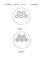
- FIG. 8 shows a circular outlet port pattern
- FIG. 9 shows a portion of a repeated hexagonal outlet port pattern.
- FIG. 10 shows a portion of a repeated triangular outlet port pattern.
- FIG. 11 shows a portion of a repeated square outlet port pattern.
- FIG. 12 shows the present invention of the high flow conductance and high thermal conductance showerhead system with a baffle.
- FIG. 13 shows a variation of the high flow conductance and high thermal conductance showerhead system with a baffle.
- FIG. 14 shows a variation of the high flow conductance and high thermal conductance showerhead system with a second high flow conductance and high thermal conductance showerhead plate acting as a baffle.
- FIG. 15 shows another variation of the high flow conductance and high thermal conductance showerhead system with a second high flow conductance and high thermal conductance showerhead plate acting as a baffle.
- FIG. 3 illustrates a high flow conductance and high thermal conductance showerhead plate according to one embodiment of the invention.
- the showerhead plate is composed of a plate 14 with thickness T having various delivery holes 18 .
- the delivery holes have different sizes, a larger size 19 and a smaller size 18 .
- the plate is heated by the heater means 13 .
- the thickness T between 3 mm and 20 mm is much thicker than prior art showerhead plate, which is typically about 1 mm. This thickness T allows a high thermal conductance from the heater means 13 to the showerhead plate 14 .
- the delivery holes have variable sizes 18 and 19 .
- the smaller size 18 between 0.2 mm and 2 mm in diameter and between 0.5 mm and 5 mm in length, allows the setting of the pressure difference across the showerhead plate.
- the larger size between 2 mm and 15 mm in dimension, allows the high flow conductance across the showerhead plate.
- the precursor flow 11 is introduced into the showerhead plate at the precursor inlet size, pass through the delivery holes 18 , and exits to the precursor outlet size 12 onto the substrate.
- the heater means 13 serves to controllably maintain the showerhead at the desired temperature for efficient operation.
- Some precursors and their by-products, especially the metal-organic precursors such as copper(hfac)L with L is a ligand such as trimethylvinylsilane, tetrakisdimethylaminetitanium (TDMAT), tetrakisdiethylaminetitanium (TDEAT), pentadiethylaminetantalum (PDMAT), condense at room temperature. Therefore the showerhead is heated above room temperature to prevent condensation. Another purpose of the heated showerhead is to maintain a warm wall environment for desorption of condensable gases that could adversely affect the chemical reaction process.
- TDMAT tetrakisdimethylaminetitanium
- TDEAT tetrakisdiethylaminetitanium
- PDMAT pentadiethylaminetantalum
- FIG. 4 illustrates a high flow conductance and high thermal conductance showerhead plate 24 according to another embodiment of the invention.
- the showerhead plate thickness T* outside the area having delivery holes 18 is much thicker than the thickness T inside the area having delivery holes 18 . This design allows higher thermal conductance from the heater means 13 while maintain the same high flow conductance across the showerhead plate 24 .
- FIG. 5 illustrates various high flow conductance and high thermal conductance showerhead plate 14 , 34 , 44 , 54 , 64 , 74 , and 84 .
- the delivery holes of the showerhead plate 14 and 44 has the larger size portion facing the side of the precursor inlet and the smaller size portion facing the precursor outlet. This design allows a more directional flow of the precursor in the outlet when exiting the showerhead plate.
- the delivery holes of the showerhead plate 34 and 54 has the smaller size portion facing the side of the precursor inlet and the larger size portion facing the precursor outlet. This design allows a more diffusive flow of the precursor in the outlet when exiting the showerhead plate.
- the delivery holes of the showerhead plate 64 , 74 and 84 has the larger size portion sandwiching the smaller size portion with the larger size portion facing both the precursor inlet and outlet. Similar to 34 and 54 design, this design allows a more diffusive flow of the precursor in the outlet when exiting the showerhead plate.
- FIG. 6 illustrates a high flow conductance and high thermal conductance showerhead plate 14 according to another embodiment of the invention.
- the delivery holes 29 are tilted outward to deliver precursor to an area larger than the area covered by the delivery holes 29 .
- This design allows the distribution of the outlet precursor to be more uniform in a larger area.
- the area covered by the precursor outlet is the same as the area covered by the delivery holes.
- FIG. 7 illustrates a high flow conductance and high thermal conductance showerhead plate 14 according to another embodiment of the invention.
- the heater means 23 is embedded in the showerhead plate 14 . This design allows much higher thermal conductance to the showerhead plate at the expense of fabrication complexity.
- FIG. 8 shows the concentric ring pattern of the outlet ports for the showerhead plate.
- the smaller portion of the outlet ports diameter ranges from 0.2 mm to 2 mm and the larger portion of the outlet ports diameter ranges from mm to 15 mm.
- the number of concentric ring ranges from 5 to 40.
- FIG. 9 shows the hexagonal pattern of the outlet ports.
- the diameter of the hexagonal ranges from 5 mm to 20 mm.
- FIG. 10 shows the triangular pattern of the outlet ports.
- the distance between 2 adjacent inlet ports ranges from 2 mm to 15 mm.
- FIG. 11 shows the square pattern of the outlet ports.
- the distance between 2 adjacent inlet ports ranges from 2 mm to 15 mm.
- FIG. 12 illustrates a high flow conductance and high thermal conductance showerhead system according to one embodiment of the invention.
- the showerhead system employs a high flow conductance and high thermal conductance showerhead plate 104 .
- the precursor enters the inlet port 101 , diffuses through the baffle 110 , mixing in the showerhead interior volume, and exits through the showerhead plate 104 by the delivery holes 108 to the substrate below 102 .
- the delivery holes has a larger size portion 109 to maintain high flow conductance and a smaller size portion 108 to maintain the desired pressure difference.
- the heater means 103 serves to transfer thermal energy to the showerhead plate 104 .
- the showerhead plate 104 has high thermal conductance due to its design to allow efficient heat transfer from the heater means 103 .
- FIG. 13 illustrates another high flow conductance and high thermal conductance showerhead system according to one embodiment of the invention.
- the showerhead system employs a high flow conductance and high thermal conductance showerhead plate 104 together with the plate cover 112 .
- the showerhead plate 104 and the plate cover 112 forms the showerhead interior volume for precursor mixing before exiting to the substrate.
- the plate cover 112 is heated by a second heater means 111 .
- FIG. 14 illustrates another high flow conductance and high thermal conductance showerhead system according to one embodiment of the invention.
- the showerhead system employs two high flow conductance and high thermal conductance showerhead plates 104 and 204 .
- the first showerhead plate 204 serves as a baffle to bring the precursor inlet 101 from a small area to a much larger area 211 .
- the second showerhead plate 104 delivers precursor perpendicular 102 to the substrate.
- the delivery holes 229 of the first showerhead plate 204 are tilted outward to diffuse the precursor while the delivery holes 108 of the second showerhead plate 104 are perpendicular to deliver the precursor uniformly.
- Heater means 203 supplies thermal energy to the first showerhead plate 204 and heater means 103 supplies thermal energy to the second showerhead plate 104 .
- FIG. 15 illustrates another high flow conductance and high thermal conductance showerhead system according to one embodiment of the invention.
- the showerhead system employs two high flow conductance and high thermal conductance showerhead plates 104 and 304 .
- the first showerhead plate 304 has two different thickness, one at the area of the delivery holes and another, thicker, at the edge of the showerhead plate for better thermal conduction.
Abstract
Description
Claims (11)
Priority Applications (1)
| Application Number | Priority Date | Filing Date | Title |
|---|---|---|---|
| US09/325,835 US6565661B1 (en) | 1999-06-04 | 1999-06-04 | High flow conductance and high thermal conductance showerhead system and method |
Applications Claiming Priority (1)
| Application Number | Priority Date | Filing Date | Title |
|---|---|---|---|
| US09/325,835 US6565661B1 (en) | 1999-06-04 | 1999-06-04 | High flow conductance and high thermal conductance showerhead system and method |
Publications (1)
| Publication Number | Publication Date |
|---|---|
| US6565661B1 true US6565661B1 (en) | 2003-05-20 |
Family
ID=23269650
Family Applications (1)
| Application Number | Title | Priority Date | Filing Date |
|---|---|---|---|
| US09/325,835 Expired - Lifetime US6565661B1 (en) | 1999-06-04 | 1999-06-04 | High flow conductance and high thermal conductance showerhead system and method |
Country Status (1)
| Country | Link |
|---|---|
| US (1) | US6565661B1 (en) |
Cited By (174)
| Publication number | Priority date | Publication date | Assignee | Title |
|---|---|---|---|---|
| US20020020767A1 (en) * | 2000-06-19 | 2002-02-21 | Pyo Sung Gyu | Showerhead and liquid raw material supply apparatus using the same |
| US20030097987A1 (en) * | 2001-11-27 | 2003-05-29 | Asm Japan K.K. | Plasma CVD apparatus conducting self-cleaning and method of self-cleaning |
| US20040052969A1 (en) * | 2002-09-16 | 2004-03-18 | Applied Materials, Inc. | Methods for operating a chemical vapor deposition chamber using a heated gas distribution plate |
| US20040060514A1 (en) * | 2002-01-25 | 2004-04-01 | Applied Materials, Inc. A Delaware Corporation | Gas distribution showerhead |
| US20040123800A1 (en) * | 2002-08-08 | 2004-07-01 | Ole Schlottmann | Showerheads |
| US20040129211A1 (en) * | 2003-01-07 | 2004-07-08 | Applied Materials, Inc. | Tunable gas distribution plate assembly |
| US20040166695A1 (en) * | 2002-09-19 | 2004-08-26 | Applied Materials, Inc. | Limited thermal budget formation of PMD layers |
| US6793733B2 (en) * | 2002-01-25 | 2004-09-21 | Applied Materials Inc. | Gas distribution showerhead |
| US20040206305A1 (en) * | 2003-04-16 | 2004-10-21 | Applied Materials, Inc. | Gas distribution plate assembly for large area plasma enhanced chemical vapor deposition |
| US20040235299A1 (en) * | 2003-05-22 | 2004-11-25 | Axcelis Technologies, Inc. | Plasma ashing apparatus and endpoint detection process |
| US20040238123A1 (en) * | 2003-05-22 | 2004-12-02 | Axcelis Technologies, Inc. | Plasma apparatus, gas distribution assembly for a plasma apparatus and processes therewith |
| US20050056217A1 (en) * | 2003-08-06 | 2005-03-17 | Takakazu Yamada | Shower head, device and method for manufacturing thin films |
| US20050098106A1 (en) * | 2003-11-12 | 2005-05-12 | Tokyo Electron Limited | Method and apparatus for improved electrode plate |
| US20050223986A1 (en) * | 2004-04-12 | 2005-10-13 | Choi Soo Y | Gas diffusion shower head design for large area plasma enhanced chemical vapor deposition |
| US20050251990A1 (en) * | 2004-05-12 | 2005-11-17 | Applied Materials, Inc. | Plasma uniformity control by gas diffuser hole design |
| US20060021703A1 (en) * | 2004-07-29 | 2006-02-02 | Applied Materials, Inc. | Dual gas faceplate for a showerhead in a semiconductor wafer processing system |
| US20060030165A1 (en) * | 2004-08-04 | 2006-02-09 | Applied Materials, Inc. A Delaware Corporation | Multi-step anneal of thin films for film densification and improved gap-fill |
| US20060086319A1 (en) * | 2003-06-10 | 2006-04-27 | Tokyo Electron Limited | Processing gas supply mechanism, film forming apparatus and method, and computer storage medium storing program for controlling same |
| US20060124061A1 (en) * | 2004-12-13 | 2006-06-15 | Tateo Saito | Molecule supply source for use in thin-film forming |
| US20060289116A1 (en) * | 2001-03-28 | 2006-12-28 | Tadahiro Ohmi | Plasma processing apparatus |
| US20070059896A1 (en) * | 2002-09-19 | 2007-03-15 | Applied Materials, Inc. | Nitrous oxide anneal of teos/ozone cvd for improved gapfill |
| US20070144671A1 (en) * | 2003-12-26 | 2007-06-28 | Foundation For Advacement Of International Science | Shower plate, plasma processing apparatus, and product manufacturing method |
| US20070163497A1 (en) * | 2006-01-17 | 2007-07-19 | Eastman Kodak Company | Two-dimensional aperture array for vapor deposition |
| US20070212850A1 (en) * | 2002-09-19 | 2007-09-13 | Applied Materials, Inc. | Gap-fill depositions in the formation of silicon containing dielectric materials |
| US20070212847A1 (en) * | 2004-08-04 | 2007-09-13 | Applied Materials, Inc. | Multi-step anneal of thin films for film densification and improved gap-fill |
| US20070281106A1 (en) * | 2006-05-30 | 2007-12-06 | Applied Materials, Inc. | Process chamber for dielectric gapfill |
| US20080000424A1 (en) * | 2006-06-29 | 2008-01-03 | Aviza Technology, Inc. | Showerhead for a Gas Supply Apparatus |
| US20080020146A1 (en) * | 2004-05-12 | 2008-01-24 | Choi Soo Y | Diffuser plate with slit valve compensation |
| US20080078744A1 (en) * | 2006-09-28 | 2008-04-03 | Lam Research Corporation | High chamber temperature process and chamber design for photo-resist stripping and post-metal etch passivation |
| US20080115726A1 (en) * | 2004-08-27 | 2008-05-22 | Applied Materials, Inc. | gap-fill depositions introducing hydroxyl-containing precursors in the formation of silicon containing dielectric materials |
| US20080141941A1 (en) * | 2006-12-18 | 2008-06-19 | Lam Research Corporation | Showerhead electrode assembly with gas flow modification for extended electrode life |
| US20080152840A1 (en) * | 2006-12-22 | 2008-06-26 | Applied Materials, Inc. | Apparatus for integrated gas and radiation delivery |
| US20080156264A1 (en) * | 2006-12-27 | 2008-07-03 | Novellus Systems, Inc. | Plasma Generator Apparatus |
| US7456116B2 (en) | 2002-09-19 | 2008-11-25 | Applied Materials, Inc. | Gap-fill depositions in the formation of silicon containing dielectric materials |
| US20090044753A1 (en) * | 2006-06-23 | 2009-02-19 | Deenesh Padhi | Methods to improve the in-film defectivity of pecvd amorphous carbon films |
| US20090061083A1 (en) * | 2007-09-05 | 2009-03-05 | Chiang Tony P | Vapor based combinatorial processing |
| US20090120584A1 (en) * | 2007-11-08 | 2009-05-14 | Applied Materials, Inc. | Counter-balanced substrate support |
| US20090120368A1 (en) * | 2007-11-08 | 2009-05-14 | Applied Materials, Inc. | Rotating temperature controlled substrate pedestal for film uniformity |
| US20090159001A1 (en) * | 2004-08-11 | 2009-06-25 | Pyung-Yong Um | Shower head of chemical vapor deposition apparatus |
| US20090236313A1 (en) * | 2008-03-20 | 2009-09-24 | Novellus Systems, Inc. | Gas flow distribution receptacles, plasma generator systems, and methods for performing plasma stripping processes |
| US20090250334A1 (en) * | 2008-04-03 | 2009-10-08 | Novellus Systems, Inc. | Plasma generator systems and methods of forming plasma |
| US20090275210A1 (en) * | 2008-05-02 | 2009-11-05 | Sunil Shanker | Combinatorial plasma enhanced deposition techniques |
| US20090277587A1 (en) * | 2008-05-09 | 2009-11-12 | Applied Materials, Inc. | Flowable dielectric equipment and processes |
| US20100136216A1 (en) * | 2008-12-01 | 2010-06-03 | Applied Materials, Inc. | Gas distribution blocker apparatus |
| US20100166957A1 (en) * | 2003-08-07 | 2010-07-01 | Sundew Technologies, Llc | Perimeter partition-valve with protected seals and associated small size process chambers and multiple chamber systems |
| US20100170441A1 (en) * | 2006-07-10 | 2010-07-08 | Won Seok-Jun | Method of Forming Metal Oxide and Apparatus for Performing the Same |
| US20100247766A1 (en) * | 2009-03-25 | 2010-09-30 | University Of Michigan | Nozzle geometry for organic vapor jet printing |
| US20100311249A1 (en) * | 2009-06-09 | 2010-12-09 | Applied Materials, Inc. | Multi-gas flow diffuser |
| DE102010000388A1 (en) * | 2010-02-11 | 2011-08-11 | Aixtron Ag, 52134 | Gas inlet element with baffle plate arrangement |
| US20110256692A1 (en) * | 2010-04-14 | 2011-10-20 | Applied Materials, Inc. | Multiple precursor concentric delivery showerhead |
| US20120034786A1 (en) * | 2010-08-04 | 2012-02-09 | Lam Research Corporation | Plasma Processing Chamber with Dual Axial Gas Injection and Exhaust |
| US20120073753A1 (en) * | 2010-09-27 | 2012-03-29 | Tokyo Electron Limited | Electrode plate for plasma etching and plasma etching apparatus |
| WO2012084661A1 (en) * | 2010-12-23 | 2012-06-28 | Element Six Limited | A microwave plasma reactor for manufacturing synthetic diamond material |
| US20120247673A1 (en) * | 2011-03-31 | 2012-10-04 | Tokyo Electron Limited | Electrode having gas discharge function and plasma processing apparatus |
| EP2656370A2 (en) | 2010-12-23 | 2013-10-30 | Element Six Limited | Microwave plasma reactors and substrates for synthetic diamond manufacture |
| US20140116339A1 (en) * | 2011-06-11 | 2014-05-01 | Tokyo Electron Limited | Process gas diffuser assembly for vapor deposition system |
| DE102012111218A1 (en) * | 2012-11-21 | 2014-05-22 | Emdeoled Gmbh | Material discharge head of material discharge device comprises material discharge surface comprising material discharge openings, and connecting channel for direct connection to the material discharge opening with material storage container |
| US20140165911A1 (en) * | 2012-12-14 | 2014-06-19 | Applied Materials, Inc. | Apparatus for providing plasma to a process chamber |
| US20140202388A1 (en) * | 2008-09-30 | 2014-07-24 | Eugene Technology Co., Ltd. | Shower head unit and chemical vapor deposition apparatus |
| US8916022B1 (en) | 2008-09-12 | 2014-12-23 | Novellus Systems, Inc. | Plasma generator systems and methods of forming plasma |
| US20150007771A1 (en) * | 2011-07-12 | 2015-01-08 | Aixtron Se | Gas inlet member of a cvd reactor |
| US20150007770A1 (en) * | 2013-07-03 | 2015-01-08 | Novellus Systems, Inc. | Multi-plenum, dual-temperature showerhead |
| US8955456B2 (en) | 2010-12-23 | 2015-02-17 | Element Six Limited | Microwave plasma reactor for manufacturing synthetic diamond material |
| US9018108B2 (en) | 2013-01-25 | 2015-04-28 | Applied Materials, Inc. | Low shrinkage dielectric films |
| JP2015096463A (en) * | 2010-12-23 | 2015-05-21 | エレメント シックス リミテッド | Doping control of synthetic diamond material |
| US20150214009A1 (en) * | 2014-01-25 | 2015-07-30 | Yuri Glukhoy | Showerhead-cooler system of a semiconductor-processing chamber for semiconductor wafers of large area |
| US9129778B2 (en) | 2011-03-18 | 2015-09-08 | Lam Research Corporation | Fluid distribution members and/or assemblies |
| US9144147B2 (en) | 2011-01-18 | 2015-09-22 | Applied Materials, Inc. | Semiconductor processing system and methods using capacitively coupled plasma |
| US9142389B2 (en) | 2010-12-23 | 2015-09-22 | Element Six Technologies Limited | Microwave power delivery system for plasma reactors |
| US20150315706A1 (en) * | 2014-05-05 | 2015-11-05 | Lam Research Corporation | Low volume showerhead with porous baffle |
| US9184028B2 (en) | 2010-08-04 | 2015-11-10 | Lam Research Corporation | Dual plasma volume processing apparatus for neutral/ion flux control |
| US9410242B2 (en) | 2010-12-23 | 2016-08-09 | Element Six Technologies Limited | Microwave plasma reactor for manufacturing synthetic diamond material |
| US20170062184A1 (en) * | 2015-08-27 | 2017-03-02 | Applied Materials, Inc. | Plasma etching systems and methods with secondary plasma injection |
| US20170268711A1 (en) * | 2016-03-15 | 2017-09-21 | Kabushiki Kaisha Toshiba | Branching structure |
| US20180096821A1 (en) * | 2016-10-04 | 2018-04-05 | Applied Materials, Inc. | Dual-channel showerhead with improved profile |
| US9947549B1 (en) | 2016-10-10 | 2018-04-17 | Applied Materials, Inc. | Cobalt-containing material removal |
| US9966240B2 (en) | 2014-10-14 | 2018-05-08 | Applied Materials, Inc. | Systems and methods for internal surface conditioning assessment in plasma processing equipment |
| US9978564B2 (en) | 2012-09-21 | 2018-05-22 | Applied Materials, Inc. | Chemical control features in wafer process equipment |
| US10023959B2 (en) | 2015-05-26 | 2018-07-17 | Lam Research Corporation | Anti-transient showerhead |
| US10026621B2 (en) | 2016-11-14 | 2018-07-17 | Applied Materials, Inc. | SiN spacer profile patterning |
| US10032606B2 (en) | 2012-08-02 | 2018-07-24 | Applied Materials, Inc. | Semiconductor processing with DC assisted RF power for improved control |
| US10043674B1 (en) | 2017-08-04 | 2018-08-07 | Applied Materials, Inc. | Germanium etching systems and methods |
| US10043684B1 (en) | 2017-02-06 | 2018-08-07 | Applied Materials, Inc. | Self-limiting atomic thermal etching systems and methods |
| US10049891B1 (en) | 2017-05-31 | 2018-08-14 | Applied Materials, Inc. | Selective in situ cobalt residue removal |
| US10062585B2 (en) | 2016-10-04 | 2018-08-28 | Applied Materials, Inc. | Oxygen compatible plasma source |
| US10062575B2 (en) | 2016-09-09 | 2018-08-28 | Applied Materials, Inc. | Poly directional etch by oxidation |
| US10128086B1 (en) | 2017-10-24 | 2018-11-13 | Applied Materials, Inc. | Silicon pretreatment for nitride removal |
| US10147620B2 (en) | 2015-08-06 | 2018-12-04 | Applied Materials, Inc. | Bolted wafer chuck thermal management systems and methods for wafer processing systems |
| US10163696B2 (en) | 2016-11-11 | 2018-12-25 | Applied Materials, Inc. | Selective cobalt removal for bottom up gapfill |
| US10170336B1 (en) | 2017-08-04 | 2019-01-01 | Applied Materials, Inc. | Methods for anisotropic control of selective silicon removal |
| US10186428B2 (en) | 2016-11-11 | 2019-01-22 | Applied Materials, Inc. | Removal methods for high aspect ratio structures |
| US10224180B2 (en) | 2016-10-04 | 2019-03-05 | Applied Materials, Inc. | Chamber with flow-through source |
| US10224210B2 (en) | 2014-12-09 | 2019-03-05 | Applied Materials, Inc. | Plasma processing system with direct outlet toroidal plasma source |
| US10221484B2 (en) | 2007-10-16 | 2019-03-05 | Novellus Systems, Inc. | Temperature controlled showerhead |
| US10242908B2 (en) | 2016-11-14 | 2019-03-26 | Applied Materials, Inc. | Airgap formation with damage-free copper |
| US10256079B2 (en) | 2013-02-08 | 2019-04-09 | Applied Materials, Inc. | Semiconductor processing systems having multiple plasma configurations |
| US10256112B1 (en) | 2017-12-08 | 2019-04-09 | Applied Materials, Inc. | Selective tungsten removal |
| US10283324B1 (en) | 2017-10-24 | 2019-05-07 | Applied Materials, Inc. | Oxygen treatment for nitride etching |
| US10283321B2 (en) | 2011-01-18 | 2019-05-07 | Applied Materials, Inc. | Semiconductor processing system and methods using capacitively coupled plasma |
| US20190145001A1 (en) * | 2017-11-16 | 2019-05-16 | Samsung Electronics Co., Ltd. | Deposition apparatus including upper shower head and lower shower head |
| US10297458B2 (en) | 2017-08-07 | 2019-05-21 | Applied Materials, Inc. | Process window widening using coated parts in plasma etch processes |
| US10319603B2 (en) | 2016-10-07 | 2019-06-11 | Applied Materials, Inc. | Selective SiN lateral recess |
| US10316409B2 (en) | 2012-12-21 | 2019-06-11 | Novellus Systems, Inc. | Radical source design for remote plasma atomic layer deposition |
| US10319649B2 (en) | 2017-04-11 | 2019-06-11 | Applied Materials, Inc. | Optical emission spectroscopy (OES) for remote plasma monitoring |
| US10319600B1 (en) | 2018-03-12 | 2019-06-11 | Applied Materials, Inc. | Thermal silicon etch |
| US10319739B2 (en) | 2017-02-08 | 2019-06-11 | Applied Materials, Inc. | Accommodating imperfectly aligned memory holes |
| US10354889B2 (en) | 2017-07-17 | 2019-07-16 | Applied Materials, Inc. | Non-halogen etching of silicon-containing materials |
| US20190221403A1 (en) * | 2018-01-15 | 2019-07-18 | Samsung Electronics Co., Ltd. | Plasma processing apparatus including shower head with sub-gas ports and related shower heads |
| US10378107B2 (en) | 2015-05-22 | 2019-08-13 | Lam Research Corporation | Low volume showerhead with faceplate holes for improved flow uniformity |
| US10403507B2 (en) | 2017-02-03 | 2019-09-03 | Applied Materials, Inc. | Shaped etch profile with oxidation |
| US10400333B2 (en) | 2011-03-04 | 2019-09-03 | Novellus Systems, Inc. | Hybrid ceramic showerhead |
| US10403477B2 (en) | 2010-12-23 | 2019-09-03 | Element Six Technologies Limited | Microwave plasma reactor for manufacturing synthetic diamond material |
| US10424464B2 (en) | 2015-08-07 | 2019-09-24 | Applied Materials, Inc. | Oxide etch selectivity systems and methods |
| US10424485B2 (en) | 2013-03-01 | 2019-09-24 | Applied Materials, Inc. | Enhanced etching processes using remote plasma sources |
| US20190295826A1 (en) * | 2010-10-15 | 2019-09-26 | Applied Materials, Inc. | Method and apparatus for reducing particle defects in plasma etch chambers |
| US10431429B2 (en) | 2017-02-03 | 2019-10-01 | Applied Materials, Inc. | Systems and methods for radial and azimuthal control of plasma uniformity |
| US10468276B2 (en) | 2015-08-06 | 2019-11-05 | Applied Materials, Inc. | Thermal management systems and methods for wafer processing systems |
| US10468267B2 (en) | 2017-05-31 | 2019-11-05 | Applied Materials, Inc. | Water-free etching methods |
| US10468285B2 (en) | 2015-02-03 | 2019-11-05 | Applied Materials, Inc. | High temperature chuck for plasma processing systems |
| US10465294B2 (en) | 2014-05-28 | 2019-11-05 | Applied Materials, Inc. | Oxide and metal removal |
| US10490406B2 (en) | 2018-04-10 | 2019-11-26 | Appled Materials, Inc. | Systems and methods for material breakthrough |
| US10497573B2 (en) | 2018-03-13 | 2019-12-03 | Applied Materials, Inc. | Selective atomic layer etching of semiconductor materials |
| US10504754B2 (en) | 2016-05-19 | 2019-12-10 | Applied Materials, Inc. | Systems and methods for improved semiconductor etching and component protection |
| US10522371B2 (en) | 2016-05-19 | 2019-12-31 | Applied Materials, Inc. | Systems and methods for improved semiconductor etching and component protection |
| US10541246B2 (en) | 2017-06-26 | 2020-01-21 | Applied Materials, Inc. | 3D flash memory cells which discourage cross-cell electrical tunneling |
| US10541184B2 (en) | 2017-07-11 | 2020-01-21 | Applied Materials, Inc. | Optical emission spectroscopic techniques for monitoring etching |
| US10566206B2 (en) | 2016-12-27 | 2020-02-18 | Applied Materials, Inc. | Systems and methods for anisotropic material breakthrough |
| US10573496B2 (en) | 2014-12-09 | 2020-02-25 | Applied Materials, Inc. | Direct outlet toroidal plasma source |
| US10573527B2 (en) | 2018-04-06 | 2020-02-25 | Applied Materials, Inc. | Gas-phase selective etching systems and methods |
| US10593523B2 (en) | 2014-10-14 | 2020-03-17 | Applied Materials, Inc. | Systems and methods for internal surface conditioning in plasma processing equipment |
| US10593560B2 (en) | 2018-03-01 | 2020-03-17 | Applied Materials, Inc. | Magnetic induction plasma source for semiconductor processes and equipment |
| US10604841B2 (en) | 2016-12-14 | 2020-03-31 | Lam Research Corporation | Integrated showerhead with thermal control for delivering radical and precursor gas to a downstream chamber to enable remote plasma film deposition |
| US10615047B2 (en) | 2018-02-28 | 2020-04-07 | Applied Materials, Inc. | Systems and methods to form airgaps |
| KR20200038317A (en) * | 2017-08-31 | 2020-04-10 | 램 리써치 코포레이션 | PECVD deposition system for deposition on selected sides of the substrate |
| US10629473B2 (en) | 2016-09-09 | 2020-04-21 | Applied Materials, Inc. | Footing removal for nitride spacer |
| US10672642B2 (en) | 2018-07-24 | 2020-06-02 | Applied Materials, Inc. | Systems and methods for pedestal configuration |
| DE102018130859A1 (en) * | 2018-12-04 | 2020-06-04 | Aixtron Se | CVD reactor with a gas inlet element covered by a screen plate arrangement |
| US10679870B2 (en) | 2018-02-15 | 2020-06-09 | Applied Materials, Inc. | Semiconductor processing chamber multistage mixing apparatus |
| US10699879B2 (en) | 2018-04-17 | 2020-06-30 | Applied Materials, Inc. | Two piece electrode assembly with gap for plasma control |
| US10727080B2 (en) | 2017-07-07 | 2020-07-28 | Applied Materials, Inc. | Tantalum-containing material removal |
| US10755941B2 (en) | 2018-07-06 | 2020-08-25 | Applied Materials, Inc. | Self-limiting selective etching systems and methods |
| US10854426B2 (en) | 2018-01-08 | 2020-12-01 | Applied Materials, Inc. | Metal recess for semiconductor structures |
| US10872778B2 (en) | 2018-07-06 | 2020-12-22 | Applied Materials, Inc. | Systems and methods utilizing solid-phase etchants |
| US10886137B2 (en) | 2018-04-30 | 2021-01-05 | Applied Materials, Inc. | Selective nitride removal |
| US10892198B2 (en) | 2018-09-14 | 2021-01-12 | Applied Materials, Inc. | Systems and methods for improved performance in semiconductor processing |
| US10903054B2 (en) | 2017-12-19 | 2021-01-26 | Applied Materials, Inc. | Multi-zone gas distribution systems and methods |
| US10920320B2 (en) | 2017-06-16 | 2021-02-16 | Applied Materials, Inc. | Plasma health determination in semiconductor substrate processing reactors |
| US10920319B2 (en) | 2019-01-11 | 2021-02-16 | Applied Materials, Inc. | Ceramic showerheads with conductive electrodes |
| US10943834B2 (en) | 2017-03-13 | 2021-03-09 | Applied Materials, Inc. | Replacement contact process |
| US10964512B2 (en) | 2018-02-15 | 2021-03-30 | Applied Materials, Inc. | Semiconductor processing chamber multistage mixing apparatus and methods |
| US11015247B2 (en) | 2017-12-08 | 2021-05-25 | Lam Research Corporation | Integrated showerhead with improved hole pattern for delivering radical and precursor gas to a downstream chamber to enable remote plasma film deposition |
| US11018045B2 (en) | 2017-11-16 | 2021-05-25 | Samsung Electronics Co., Ltd. | Deposition apparatus including upper shower head and lower shower head |
| US11049755B2 (en) | 2018-09-14 | 2021-06-29 | Applied Materials, Inc. | Semiconductor substrate supports with embedded RF shield |
| US11062887B2 (en) | 2018-09-17 | 2021-07-13 | Applied Materials, Inc. | High temperature RF heater pedestals |
| US11121002B2 (en) | 2018-10-24 | 2021-09-14 | Applied Materials, Inc. | Systems and methods for etching metals and metal derivatives |
| US11205751B2 (en) | 2012-03-13 | 2021-12-21 | Universal Display Corporation | Nozzle design for organic vapor jet printing |
| US11239061B2 (en) | 2014-11-26 | 2022-02-01 | Applied Materials, Inc. | Methods and systems to enhance process uniformity |
| US11257693B2 (en) | 2015-01-09 | 2022-02-22 | Applied Materials, Inc. | Methods and systems to improve pedestal temperature control |
| US11276559B2 (en) | 2017-05-17 | 2022-03-15 | Applied Materials, Inc. | Semiconductor processing chamber for multiple precursor flow |
| US11276590B2 (en) | 2017-05-17 | 2022-03-15 | Applied Materials, Inc. | Multi-zone semiconductor substrate supports |
| US11286565B2 (en) * | 2018-12-13 | 2022-03-29 | Xia Tai Xin Semiconductor (Qing Dao) Ltd. | Apparatus and method for semiconductor fabrication |
| US11328909B2 (en) | 2017-12-22 | 2022-05-10 | Applied Materials, Inc. | Chamber conditioning and removal processes |
| US11332827B2 (en) * | 2019-03-27 | 2022-05-17 | Applied Materials, Inc. | Gas distribution plate with high aspect ratio holes and a high hole density |
| US11384432B2 (en) * | 2015-04-22 | 2022-07-12 | Applied Materials, Inc. | Atomic layer deposition chamber with funnel-shaped gas dispersion channel and gas distribution plate |
| US11417534B2 (en) | 2018-09-21 | 2022-08-16 | Applied Materials, Inc. | Selective material removal |
| US11437242B2 (en) | 2018-11-27 | 2022-09-06 | Applied Materials, Inc. | Selective removal of silicon-containing materials |
| WO2022258446A1 (en) | 2021-06-09 | 2022-12-15 | Aixtron Se | Gas-inlet element for a cvd reactor |
| US11584993B2 (en) * | 2020-10-19 | 2023-02-21 | Applied Materials, Inc. | Thermally uniform deposition station |
| US11594428B2 (en) | 2015-02-03 | 2023-02-28 | Applied Materials, Inc. | Low temperature chuck for plasma processing systems |
| US11598003B2 (en) * | 2017-09-12 | 2023-03-07 | Applied Materials, Inc. | Substrate processing chamber having heated showerhead assembly |
| US11682560B2 (en) | 2018-10-11 | 2023-06-20 | Applied Materials, Inc. | Systems and methods for hafnium-containing film removal |
| US11721527B2 (en) | 2019-01-07 | 2023-08-08 | Applied Materials, Inc. | Processing chamber mixing systems |
| US11859284B2 (en) * | 2019-08-23 | 2024-01-02 | Taiwan Semiconductor Manufacturing Company Ltd. | Shower head structure and plasma processing apparatus using the same |
| US11946142B2 (en) | 2019-08-16 | 2024-04-02 | Lam Research Corporation | Spatially tunable deposition to compensate within wafer differential bow |
Citations (7)
| Publication number | Priority date | Publication date | Assignee | Title |
|---|---|---|---|---|
| JPS5737821A (en) * | 1980-08-20 | 1982-03-02 | Kokusai Electric Co Ltd | Vapor phase reaction device |
| US4590042A (en) * | 1984-12-24 | 1986-05-20 | Tegal Corporation | Plasma reactor having slotted manifold |
| US4792378A (en) * | 1987-12-15 | 1988-12-20 | Texas Instruments Incorporated | Gas dispersion disk for use in plasma enhanced chemical vapor deposition reactor |
| US5268034A (en) * | 1991-06-25 | 1993-12-07 | Lsi Logic Corporation | Fluid dispersion head for CVD appratus |
| US5464499A (en) | 1992-06-24 | 1995-11-07 | Texas Instruments Incorporated | Multi-electrode plasma processing apparatus |
| US5624498A (en) * | 1993-12-22 | 1997-04-29 | Samsung Electronics Co., Ltd. | Showerhead for a gas supplying apparatus |
| US5728223A (en) * | 1995-06-09 | 1998-03-17 | Ebara Corporation | Reactant gas ejector head and thin-film vapor deposition apparatus |
-
1999
- 1999-06-04 US US09/325,835 patent/US6565661B1/en not_active Expired - Lifetime
Patent Citations (7)
| Publication number | Priority date | Publication date | Assignee | Title |
|---|---|---|---|---|
| JPS5737821A (en) * | 1980-08-20 | 1982-03-02 | Kokusai Electric Co Ltd | Vapor phase reaction device |
| US4590042A (en) * | 1984-12-24 | 1986-05-20 | Tegal Corporation | Plasma reactor having slotted manifold |
| US4792378A (en) * | 1987-12-15 | 1988-12-20 | Texas Instruments Incorporated | Gas dispersion disk for use in plasma enhanced chemical vapor deposition reactor |
| US5268034A (en) * | 1991-06-25 | 1993-12-07 | Lsi Logic Corporation | Fluid dispersion head for CVD appratus |
| US5464499A (en) | 1992-06-24 | 1995-11-07 | Texas Instruments Incorporated | Multi-electrode plasma processing apparatus |
| US5624498A (en) * | 1993-12-22 | 1997-04-29 | Samsung Electronics Co., Ltd. | Showerhead for a gas supplying apparatus |
| US5728223A (en) * | 1995-06-09 | 1998-03-17 | Ebara Corporation | Reactant gas ejector head and thin-film vapor deposition apparatus |
Cited By (293)
| Publication number | Priority date | Publication date | Assignee | Title |
|---|---|---|---|---|
| US20020020767A1 (en) * | 2000-06-19 | 2002-02-21 | Pyo Sung Gyu | Showerhead and liquid raw material supply apparatus using the same |
| US20060289116A1 (en) * | 2001-03-28 | 2006-12-28 | Tadahiro Ohmi | Plasma processing apparatus |
| US20030097987A1 (en) * | 2001-11-27 | 2003-05-29 | Asm Japan K.K. | Plasma CVD apparatus conducting self-cleaning and method of self-cleaning |
| US20050242061A1 (en) * | 2001-11-27 | 2005-11-03 | Hideaki Fukuda | Self-cleaning method for plasma CVD apparatus |
| US6793733B2 (en) * | 2002-01-25 | 2004-09-21 | Applied Materials Inc. | Gas distribution showerhead |
| US20040060514A1 (en) * | 2002-01-25 | 2004-04-01 | Applied Materials, Inc. A Delaware Corporation | Gas distribution showerhead |
| US20040123800A1 (en) * | 2002-08-08 | 2004-07-01 | Ole Schlottmann | Showerheads |
| US20040052969A1 (en) * | 2002-09-16 | 2004-03-18 | Applied Materials, Inc. | Methods for operating a chemical vapor deposition chamber using a heated gas distribution plate |
| US20040166695A1 (en) * | 2002-09-19 | 2004-08-26 | Applied Materials, Inc. | Limited thermal budget formation of PMD layers |
| US20070212850A1 (en) * | 2002-09-19 | 2007-09-13 | Applied Materials, Inc. | Gap-fill depositions in the formation of silicon containing dielectric materials |
| US7431967B2 (en) | 2002-09-19 | 2008-10-07 | Applied Materials, Inc. | Limited thermal budget formation of PMD layers |
| US7456116B2 (en) | 2002-09-19 | 2008-11-25 | Applied Materials, Inc. | Gap-fill depositions in the formation of silicon containing dielectric materials |
| US20070059896A1 (en) * | 2002-09-19 | 2007-03-15 | Applied Materials, Inc. | Nitrous oxide anneal of teos/ozone cvd for improved gapfill |
| US7674727B2 (en) | 2002-09-19 | 2010-03-09 | Applied Materials, Inc. | Nitrous oxide anneal of TEOS/ozone CVD for improved gapfill |
| US20040129211A1 (en) * | 2003-01-07 | 2004-07-08 | Applied Materials, Inc. | Tunable gas distribution plate assembly |
| US7270713B2 (en) | 2003-01-07 | 2007-09-18 | Applied Materials, Inc. | Tunable gas distribution plate assembly |
| US6942753B2 (en) * | 2003-04-16 | 2005-09-13 | Applied Materials, Inc. | Gas distribution plate assembly for large area plasma enhanced chemical vapor deposition |
| US20040206305A1 (en) * | 2003-04-16 | 2004-10-21 | Applied Materials, Inc. | Gas distribution plate assembly for large area plasma enhanced chemical vapor deposition |
| US20100055807A1 (en) * | 2003-05-22 | 2010-03-04 | Axcelis Technologies, Inc. | Plasma ashing apparatus and endpoint detection process |
| US8268181B2 (en) | 2003-05-22 | 2012-09-18 | Axcelis Technologies, Inc. | Plasma ashing apparatus and endpoint detection process |
| US20040235299A1 (en) * | 2003-05-22 | 2004-11-25 | Axcelis Technologies, Inc. | Plasma ashing apparatus and endpoint detection process |
| US20040238123A1 (en) * | 2003-05-22 | 2004-12-02 | Axcelis Technologies, Inc. | Plasma apparatus, gas distribution assembly for a plasma apparatus and processes therewith |
| US8580076B2 (en) * | 2003-05-22 | 2013-11-12 | Lam Research Corporation | Plasma apparatus, gas distribution assembly for a plasma apparatus and processes therewith |
| US20060086319A1 (en) * | 2003-06-10 | 2006-04-27 | Tokyo Electron Limited | Processing gas supply mechanism, film forming apparatus and method, and computer storage medium storing program for controlling same |
| US20050056217A1 (en) * | 2003-08-06 | 2005-03-17 | Takakazu Yamada | Shower head, device and method for manufacturing thin films |
| US8262798B2 (en) * | 2003-08-06 | 2012-09-11 | Ulvac, Inc. | Shower head, device and method for manufacturing thin films |
| US20100166957A1 (en) * | 2003-08-07 | 2010-07-01 | Sundew Technologies, Llc | Perimeter partition-valve with protected seals and associated small size process chambers and multiple chamber systems |
| US8252116B2 (en) * | 2003-08-07 | 2012-08-28 | Sundew Technologies, Llc | Perimeter partition-valve with protected seals and associated small size process chambers and multiple chamber systems |
| WO2005033361A1 (en) * | 2003-09-29 | 2005-04-14 | Applied Materials, Inc. | Gas distribution showerhead |
| US20050098106A1 (en) * | 2003-11-12 | 2005-05-12 | Tokyo Electron Limited | Method and apparatus for improved electrode plate |
| US20070144671A1 (en) * | 2003-12-26 | 2007-06-28 | Foundation For Advacement Of International Science | Shower plate, plasma processing apparatus, and product manufacturing method |
| US7879182B2 (en) * | 2003-12-26 | 2011-02-01 | Foundation For Advancement Of International Science | Shower plate, plasma processing apparatus, and product manufacturing method |
| US20050223986A1 (en) * | 2004-04-12 | 2005-10-13 | Choi Soo Y | Gas diffusion shower head design for large area plasma enhanced chemical vapor deposition |
| US11692268B2 (en) * | 2004-04-12 | 2023-07-04 | Applied Materials, Inc. | Gas diffusion shower head design for large area plasma enhanced chemical vapor deposition |
| US20090104376A1 (en) * | 2004-04-12 | 2009-04-23 | Soo Young Choi | Gas diffusion shower head design for large area plasma enhanced chemical vapor deposition |
| US8795793B2 (en) | 2004-04-12 | 2014-08-05 | Applied Materials, Inc. | Gas diffusion shower head design for large area plasma enhanced chemical vapor deposition |
| US20140230730A1 (en) * | 2004-04-12 | 2014-08-21 | Applied Materials, Inc. | Gas diffusion shower head design for large area plasma enhanced chemical vapor deposition |
| US20080020146A1 (en) * | 2004-05-12 | 2008-01-24 | Choi Soo Y | Diffuser plate with slit valve compensation |
| US8083853B2 (en) | 2004-05-12 | 2011-12-27 | Applied Materials, Inc. | Plasma uniformity control by gas diffuser hole design |
| US20050251990A1 (en) * | 2004-05-12 | 2005-11-17 | Applied Materials, Inc. | Plasma uniformity control by gas diffuser hole design |
| US20060236934A1 (en) * | 2004-05-12 | 2006-10-26 | Choi Soo Y | Plasma uniformity control by gas diffuser hole design |
| US9200368B2 (en) | 2004-05-12 | 2015-12-01 | Applied Materials, Inc. | Plasma uniformity control by gas diffuser hole design |
| US10262837B2 (en) | 2004-05-12 | 2019-04-16 | Applied Materials, Inc. | Plasma uniformity control by gas diffuser hole design |
| US8328939B2 (en) | 2004-05-12 | 2012-12-11 | Applied Materials, Inc. | Diffuser plate with slit valve compensation |
| US10312058B2 (en) | 2004-05-12 | 2019-06-04 | Applied Materials, Inc. | Plasma uniformity control by gas diffuser hole design |
| US20060021703A1 (en) * | 2004-07-29 | 2006-02-02 | Applied Materials, Inc. | Dual gas faceplate for a showerhead in a semiconductor wafer processing system |
| US20070212847A1 (en) * | 2004-08-04 | 2007-09-13 | Applied Materials, Inc. | Multi-step anneal of thin films for film densification and improved gap-fill |
| US7642171B2 (en) | 2004-08-04 | 2010-01-05 | Applied Materials, Inc. | Multi-step anneal of thin films for film densification and improved gap-fill |
| US20060030165A1 (en) * | 2004-08-04 | 2006-02-09 | Applied Materials, Inc. A Delaware Corporation | Multi-step anneal of thin films for film densification and improved gap-fill |
| US20070000897A1 (en) * | 2004-08-04 | 2007-01-04 | Applied Materials, Inc. | Multi-step anneal of thin films for film densification and improved gap-fill |
| US20090159001A1 (en) * | 2004-08-11 | 2009-06-25 | Pyung-Yong Um | Shower head of chemical vapor deposition apparatus |
| US20080115726A1 (en) * | 2004-08-27 | 2008-05-22 | Applied Materials, Inc. | gap-fill depositions introducing hydroxyl-containing precursors in the formation of silicon containing dielectric materials |
| JP2006169551A (en) * | 2004-12-13 | 2006-06-29 | Nippon Biitec:Kk | Molecule feeder for thin film deposition |
| US20060124061A1 (en) * | 2004-12-13 | 2006-06-15 | Tateo Saito | Molecule supply source for use in thin-film forming |
| JP4560394B2 (en) * | 2004-12-13 | 2010-10-13 | 長州産業株式会社 | Molecule supply equipment for thin film formation |
| US7645483B2 (en) | 2006-01-17 | 2010-01-12 | Eastman Kodak Company | Two-dimensional aperture array for vapor deposition |
| US20070163497A1 (en) * | 2006-01-17 | 2007-07-19 | Eastman Kodak Company | Two-dimensional aperture array for vapor deposition |
| US20070281106A1 (en) * | 2006-05-30 | 2007-12-06 | Applied Materials, Inc. | Process chamber for dielectric gapfill |
| US8282734B2 (en) * | 2006-06-23 | 2012-10-09 | Applied Materials, Inc. | Methods to improve the in-film defectivity of PECVD amorphous carbon films |
| US20090044753A1 (en) * | 2006-06-23 | 2009-02-19 | Deenesh Padhi | Methods to improve the in-film defectivity of pecvd amorphous carbon films |
| US20080000424A1 (en) * | 2006-06-29 | 2008-01-03 | Aviza Technology, Inc. | Showerhead for a Gas Supply Apparatus |
| US20100170441A1 (en) * | 2006-07-10 | 2010-07-08 | Won Seok-Jun | Method of Forming Metal Oxide and Apparatus for Performing the Same |
| US20080078744A1 (en) * | 2006-09-28 | 2008-04-03 | Lam Research Corporation | High chamber temperature process and chamber design for photo-resist stripping and post-metal etch passivation |
| US7476291B2 (en) * | 2006-09-28 | 2009-01-13 | Lam Research Corporation | High chamber temperature process and chamber design for photo-resist stripping and post-metal etch passivation |
| US8702866B2 (en) * | 2006-12-18 | 2014-04-22 | Lam Research Corporation | Showerhead electrode assembly with gas flow modification for extended electrode life |
| US20080141941A1 (en) * | 2006-12-18 | 2008-06-19 | Lam Research Corporation | Showerhead electrode assembly with gas flow modification for extended electrode life |
| US9093483B2 (en) | 2006-12-18 | 2015-07-28 | Lam Research Corporation | Showerhead electrode assembly with gas flow modification for extended electrode life |
| US7922863B2 (en) * | 2006-12-22 | 2011-04-12 | Applied Materials, Inc. | Apparatus for integrated gas and radiation delivery |
| US20080152840A1 (en) * | 2006-12-22 | 2008-06-26 | Applied Materials, Inc. | Apparatus for integrated gas and radiation delivery |
| US8864935B2 (en) | 2006-12-27 | 2014-10-21 | Novellus Systems, Inc. | Plasma generator apparatus |
| US20080156264A1 (en) * | 2006-12-27 | 2008-07-03 | Novellus Systems, Inc. | Plasma Generator Apparatus |
| US20090061083A1 (en) * | 2007-09-05 | 2009-03-05 | Chiang Tony P | Vapor based combinatorial processing |
| WO2009032958A1 (en) * | 2007-09-05 | 2009-03-12 | Intermolecular, Inc. | Vapor based combinatorial processing |
| TWI398547B (en) * | 2007-09-05 | 2013-06-11 | Intermolecular Inc | Vapor based combinatorial processing |
| US8440259B2 (en) | 2007-09-05 | 2013-05-14 | Intermolecular, Inc. | Vapor based combinatorial processing |
| US10221484B2 (en) | 2007-10-16 | 2019-03-05 | Novellus Systems, Inc. | Temperature controlled showerhead |
| US10584415B2 (en) | 2007-10-16 | 2020-03-10 | Novellus Systems, Inc. | Temperature controlled showerhead |
| US20090120368A1 (en) * | 2007-11-08 | 2009-05-14 | Applied Materials, Inc. | Rotating temperature controlled substrate pedestal for film uniformity |
| US20090120584A1 (en) * | 2007-11-08 | 2009-05-14 | Applied Materials, Inc. | Counter-balanced substrate support |
| US20150144061A1 (en) * | 2008-01-14 | 2015-05-28 | Intermolecular, Inc. | Combinatorial Plasma Enhanced Deposition Techniques |
| US8110068B2 (en) * | 2008-03-20 | 2012-02-07 | Novellus Systems, Inc. | Gas flow distribution receptacles, plasma generator systems, and methods for performing plasma stripping processes |
| US9209000B2 (en) * | 2008-03-20 | 2015-12-08 | Novellus Systems, Inc. | Gas flow distribution receptacles, plasma generator systems, and methods for performing plasma stripping processes |
| US20120097331A1 (en) * | 2008-03-20 | 2012-04-26 | Novellus Systems, Inc. | Gas flow distribution receptacles, plasma generator systems, and methods for performing plasma stripping processes |
| US20090236313A1 (en) * | 2008-03-20 | 2009-09-24 | Novellus Systems, Inc. | Gas flow distribution receptacles, plasma generator systems, and methods for performing plasma stripping processes |
| US20090250334A1 (en) * | 2008-04-03 | 2009-10-08 | Novellus Systems, Inc. | Plasma generator systems and methods of forming plasma |
| US9591738B2 (en) | 2008-04-03 | 2017-03-07 | Novellus Systems, Inc. | Plasma generator systems and methods of forming plasma |
| US8129288B2 (en) | 2008-05-02 | 2012-03-06 | Intermolecular, Inc. | Combinatorial plasma enhanced deposition techniques |
| US20090275210A1 (en) * | 2008-05-02 | 2009-11-05 | Sunil Shanker | Combinatorial plasma enhanced deposition techniques |
| US20090277587A1 (en) * | 2008-05-09 | 2009-11-12 | Applied Materials, Inc. | Flowable dielectric equipment and processes |
| US8916022B1 (en) | 2008-09-12 | 2014-12-23 | Novellus Systems, Inc. | Plasma generator systems and methods of forming plasma |
| US20140202388A1 (en) * | 2008-09-30 | 2014-07-24 | Eugene Technology Co., Ltd. | Shower head unit and chemical vapor deposition apparatus |
| US9493875B2 (en) * | 2008-09-30 | 2016-11-15 | Eugene Technology Co., Ltd. | Shower head unit and chemical vapor deposition apparatus |
| US20100136216A1 (en) * | 2008-12-01 | 2010-06-03 | Applied Materials, Inc. | Gas distribution blocker apparatus |
| US9714465B2 (en) | 2008-12-01 | 2017-07-25 | Applied Materials, Inc. | Gas distribution blocker apparatus |
| US10480056B2 (en) * | 2009-03-25 | 2019-11-19 | The Regents Of The University Of Michigan | Nozzle geometry for organic vapor jet printing |
| US20100247766A1 (en) * | 2009-03-25 | 2010-09-30 | University Of Michigan | Nozzle geometry for organic vapor jet printing |
| US10941481B2 (en) | 2009-03-25 | 2021-03-09 | The Regents Of The University Of Michigan | Nozzle geometry for organic vapor jet printing |
| US8931431B2 (en) * | 2009-03-25 | 2015-01-13 | The Regents Of The University Of Michigan | Nozzle geometry for organic vapor jet printing |
| US20100311249A1 (en) * | 2009-06-09 | 2010-12-09 | Applied Materials, Inc. | Multi-gas flow diffuser |
| US8147614B2 (en) | 2009-06-09 | 2012-04-03 | Applied Materials, Inc. | Multi-gas flow diffuser |
| DE102010000388A1 (en) * | 2010-02-11 | 2011-08-11 | Aixtron Ag, 52134 | Gas inlet element with baffle plate arrangement |
| WO2011098420A1 (en) | 2010-02-11 | 2011-08-18 | Aixtron Se | Gas inlet member with baffle plate arrangement |
| US20110256692A1 (en) * | 2010-04-14 | 2011-10-20 | Applied Materials, Inc. | Multiple precursor concentric delivery showerhead |
| US20120034786A1 (en) * | 2010-08-04 | 2012-02-09 | Lam Research Corporation | Plasma Processing Chamber with Dual Axial Gas Injection and Exhaust |
| US9793128B2 (en) * | 2010-08-04 | 2017-10-17 | Lam Research Corporation | Plasma processing chamber with dual axial gas injection and exhaust |
| US20150004793A1 (en) * | 2010-08-04 | 2015-01-01 | Lam Research Corporation | Plasma Processing Chamber with Dual Axial Gas Injection and Exhaust |
| US8869742B2 (en) * | 2010-08-04 | 2014-10-28 | Lam Research Corporation | Plasma processing chamber with dual axial gas injection and exhaust |
| US9184028B2 (en) | 2010-08-04 | 2015-11-10 | Lam Research Corporation | Dual plasma volume processing apparatus for neutral/ion flux control |
| US9818583B2 (en) * | 2010-09-27 | 2017-11-14 | Tokyo Electron Limited | Electrode plate for plasma etching and plasma etching apparatus |
| US20120073753A1 (en) * | 2010-09-27 | 2012-03-29 | Tokyo Electron Limited | Electrode plate for plasma etching and plasma etching apparatus |
| US20150348762A1 (en) * | 2010-09-27 | 2015-12-03 | Tokyo Electron Limited | Electrode plate for plasma etching and plasma etching apparatus |
| US9117635B2 (en) * | 2010-09-27 | 2015-08-25 | Tokyo Electron Limited | Electrode plate for plasma etching and plasma etching apparatus |
| US11488812B2 (en) * | 2010-10-15 | 2022-11-01 | Applied Materials, Inc. | Method and apparatus for reducing particle defects in plasma etch chambers |
| US20190295826A1 (en) * | 2010-10-15 | 2019-09-26 | Applied Materials, Inc. | Method and apparatus for reducing particle defects in plasma etch chambers |
| JP2015096463A (en) * | 2010-12-23 | 2015-05-21 | エレメント シックス リミテッド | Doping control of synthetic diamond material |
| US9410242B2 (en) | 2010-12-23 | 2016-08-09 | Element Six Technologies Limited | Microwave plasma reactor for manufacturing synthetic diamond material |
| US9142389B2 (en) | 2010-12-23 | 2015-09-22 | Element Six Technologies Limited | Microwave power delivery system for plasma reactors |
| US20150030786A1 (en) * | 2010-12-23 | 2015-01-29 | Element Six Limited | Microwave plasma reactor for manufacturing synthetic diamond material |
| US11488805B2 (en) | 2010-12-23 | 2022-11-01 | Element Six Technologies Limited | Microwave plasma reactor for manufacturing synthetic diamond material |
| JP2014503035A (en) * | 2010-12-23 | 2014-02-06 | エレメント シックス リミテッド | Microwave plasma reactor for producing synthetic diamond materials |
| EP2656373A1 (en) | 2010-12-23 | 2013-10-30 | Element Six Limited | A microwave plasma reactor for manufacturing synthetic diamond material |
| US11371147B2 (en) * | 2010-12-23 | 2022-06-28 | Element Six Technologies Limited | Microwave plasma reactor for manufacturing synthetic diamond material |
| CN103354946B (en) * | 2010-12-23 | 2016-06-29 | 六号元素有限公司 | For manufacturing the microwave plasma reactor of diamond synthesis material |
| US9738970B2 (en) | 2010-12-23 | 2017-08-22 | Element Six Limited | Microwave plasma reactors and substrates for synthetic diamond manufacture |
| US8859058B2 (en) | 2010-12-23 | 2014-10-14 | Element Six Limited | Microwave plasma reactors and substrates for synthetic diamond manufacture |
| US10403477B2 (en) | 2010-12-23 | 2019-09-03 | Element Six Technologies Limited | Microwave plasma reactor for manufacturing synthetic diamond material |
| WO2012084661A1 (en) * | 2010-12-23 | 2012-06-28 | Element Six Limited | A microwave plasma reactor for manufacturing synthetic diamond material |
| EP2656370A2 (en) | 2010-12-23 | 2013-10-30 | Element Six Limited | Microwave plasma reactors and substrates for synthetic diamond manufacture |
| US8955456B2 (en) | 2010-12-23 | 2015-02-17 | Element Six Limited | Microwave plasma reactor for manufacturing synthetic diamond material |
| CN103354946A (en) * | 2010-12-23 | 2013-10-16 | 六号元素有限公司 | A microwave plasma reactor for manufacturing synthetic diamond material |
| US9637838B2 (en) | 2010-12-23 | 2017-05-02 | Element Six Limited | Methods of manufacturing synthetic diamond material by microwave plasma enhanced chemical vapor deposition from a microwave generator and gas inlet(s) disposed opposite the growth surface area |
| US9144147B2 (en) | 2011-01-18 | 2015-09-22 | Applied Materials, Inc. | Semiconductor processing system and methods using capacitively coupled plasma |
| US10283321B2 (en) | 2011-01-18 | 2019-05-07 | Applied Materials, Inc. | Semiconductor processing system and methods using capacitively coupled plasma |
| US10400333B2 (en) | 2011-03-04 | 2019-09-03 | Novellus Systems, Inc. | Hybrid ceramic showerhead |
| US9129778B2 (en) | 2011-03-18 | 2015-09-08 | Lam Research Corporation | Fluid distribution members and/or assemblies |
| US9082593B2 (en) * | 2011-03-31 | 2015-07-14 | Tokyo Electron Limited | Electrode having gas discharge function and plasma processing apparatus |
| US20120247673A1 (en) * | 2011-03-31 | 2012-10-04 | Tokyo Electron Limited | Electrode having gas discharge function and plasma processing apparatus |
| US20140116339A1 (en) * | 2011-06-11 | 2014-05-01 | Tokyo Electron Limited | Process gas diffuser assembly for vapor deposition system |
| US9587312B2 (en) * | 2011-07-12 | 2017-03-07 | Aixtron Se | Gas inlet member of a CVD reactor |
| US20150007771A1 (en) * | 2011-07-12 | 2015-01-08 | Aixtron Se | Gas inlet member of a cvd reactor |
| US11205751B2 (en) | 2012-03-13 | 2021-12-21 | Universal Display Corporation | Nozzle design for organic vapor jet printing |
| US10032606B2 (en) | 2012-08-02 | 2018-07-24 | Applied Materials, Inc. | Semiconductor processing with DC assisted RF power for improved control |
| US9978564B2 (en) | 2012-09-21 | 2018-05-22 | Applied Materials, Inc. | Chemical control features in wafer process equipment |
| US11264213B2 (en) | 2012-09-21 | 2022-03-01 | Applied Materials, Inc. | Chemical control features in wafer process equipment |
| US10354843B2 (en) | 2012-09-21 | 2019-07-16 | Applied Materials, Inc. | Chemical control features in wafer process equipment |
| DE102012111218A1 (en) * | 2012-11-21 | 2014-05-22 | Emdeoled Gmbh | Material discharge head of material discharge device comprises material discharge surface comprising material discharge openings, and connecting channel for direct connection to the material discharge opening with material storage container |
| TWI608517B (en) * | 2012-12-14 | 2017-12-11 | 應用材料股份有限公司 | Process chamber and apparatus for providing plasma to a process chamber |
| US20140165911A1 (en) * | 2012-12-14 | 2014-06-19 | Applied Materials, Inc. | Apparatus for providing plasma to a process chamber |
| US11053587B2 (en) | 2012-12-21 | 2021-07-06 | Novellus Systems, Inc. | Radical source design for remote plasma atomic layer deposition |
| US10316409B2 (en) | 2012-12-21 | 2019-06-11 | Novellus Systems, Inc. | Radical source design for remote plasma atomic layer deposition |
| US9018108B2 (en) | 2013-01-25 | 2015-04-28 | Applied Materials, Inc. | Low shrinkage dielectric films |
| US10256079B2 (en) | 2013-02-08 | 2019-04-09 | Applied Materials, Inc. | Semiconductor processing systems having multiple plasma configurations |
| US11024486B2 (en) | 2013-02-08 | 2021-06-01 | Applied Materials, Inc. | Semiconductor processing systems having multiple plasma configurations |
| US10424485B2 (en) | 2013-03-01 | 2019-09-24 | Applied Materials, Inc. | Enhanced etching processes using remote plasma sources |
| US9677176B2 (en) * | 2013-07-03 | 2017-06-13 | Novellus Systems, Inc. | Multi-plenum, dual-temperature showerhead |
| US20150007770A1 (en) * | 2013-07-03 | 2015-01-08 | Novellus Systems, Inc. | Multi-plenum, dual-temperature showerhead |
| US9484190B2 (en) * | 2014-01-25 | 2016-11-01 | Yuri Glukhoy | Showerhead-cooler system of a semiconductor-processing chamber for semiconductor wafers of large area |
| US20150214009A1 (en) * | 2014-01-25 | 2015-07-30 | Yuri Glukhoy | Showerhead-cooler system of a semiconductor-processing chamber for semiconductor wafers of large area |
| US10741365B2 (en) * | 2014-05-05 | 2020-08-11 | Lam Research Corporation | Low volume showerhead with porous baffle |
| US20150315706A1 (en) * | 2014-05-05 | 2015-11-05 | Lam Research Corporation | Low volume showerhead with porous baffle |
| US10465294B2 (en) | 2014-05-28 | 2019-11-05 | Applied Materials, Inc. | Oxide and metal removal |
| US10796922B2 (en) | 2014-10-14 | 2020-10-06 | Applied Materials, Inc. | Systems and methods for internal surface conditioning assessment in plasma processing equipment |
| US10490418B2 (en) | 2014-10-14 | 2019-11-26 | Applied Materials, Inc. | Systems and methods for internal surface conditioning assessment in plasma processing equipment |
| US9966240B2 (en) | 2014-10-14 | 2018-05-08 | Applied Materials, Inc. | Systems and methods for internal surface conditioning assessment in plasma processing equipment |
| US10707061B2 (en) | 2014-10-14 | 2020-07-07 | Applied Materials, Inc. | Systems and methods for internal surface conditioning in plasma processing equipment |
| US10593523B2 (en) | 2014-10-14 | 2020-03-17 | Applied Materials, Inc. | Systems and methods for internal surface conditioning in plasma processing equipment |
| US11239061B2 (en) | 2014-11-26 | 2022-02-01 | Applied Materials, Inc. | Methods and systems to enhance process uniformity |
| US11637002B2 (en) | 2014-11-26 | 2023-04-25 | Applied Materials, Inc. | Methods and systems to enhance process uniformity |
| US10573496B2 (en) | 2014-12-09 | 2020-02-25 | Applied Materials, Inc. | Direct outlet toroidal plasma source |
| US10224210B2 (en) | 2014-12-09 | 2019-03-05 | Applied Materials, Inc. | Plasma processing system with direct outlet toroidal plasma source |
| US11257693B2 (en) | 2015-01-09 | 2022-02-22 | Applied Materials, Inc. | Methods and systems to improve pedestal temperature control |
| US10468285B2 (en) | 2015-02-03 | 2019-11-05 | Applied Materials, Inc. | High temperature chuck for plasma processing systems |
| US11594428B2 (en) | 2015-02-03 | 2023-02-28 | Applied Materials, Inc. | Low temperature chuck for plasma processing systems |
| US11932939B2 (en) | 2015-04-22 | 2024-03-19 | Applied Materials, Inc. | Lids and lid assembly kits for atomic layer deposition chambers |
| US11384432B2 (en) * | 2015-04-22 | 2022-07-12 | Applied Materials, Inc. | Atomic layer deposition chamber with funnel-shaped gas dispersion channel and gas distribution plate |
| US10378107B2 (en) | 2015-05-22 | 2019-08-13 | Lam Research Corporation | Low volume showerhead with faceplate holes for improved flow uniformity |
| US10494717B2 (en) | 2015-05-26 | 2019-12-03 | Lam Research Corporation | Anti-transient showerhead |
| US10023959B2 (en) | 2015-05-26 | 2018-07-17 | Lam Research Corporation | Anti-transient showerhead |
| US10607867B2 (en) | 2015-08-06 | 2020-03-31 | Applied Materials, Inc. | Bolted wafer chuck thermal management systems and methods for wafer processing systems |
| US10468276B2 (en) | 2015-08-06 | 2019-11-05 | Applied Materials, Inc. | Thermal management systems and methods for wafer processing systems |
| US11158527B2 (en) | 2015-08-06 | 2021-10-26 | Applied Materials, Inc. | Thermal management systems and methods for wafer processing systems |
| US10147620B2 (en) | 2015-08-06 | 2018-12-04 | Applied Materials, Inc. | Bolted wafer chuck thermal management systems and methods for wafer processing systems |
| US10424463B2 (en) | 2015-08-07 | 2019-09-24 | Applied Materials, Inc. | Oxide etch selectivity systems and methods |
| US10424464B2 (en) | 2015-08-07 | 2019-09-24 | Applied Materials, Inc. | Oxide etch selectivity systems and methods |
| TWI720010B (en) * | 2015-08-27 | 2021-03-01 | 美商應用材料股份有限公司 | Plasma etching systems and methods with secondary plasma injection |
| CN106486335B (en) * | 2015-08-27 | 2020-03-17 | 应用材料公司 | Plasma etching system and method using secondary plasma implantation |
| US10504700B2 (en) * | 2015-08-27 | 2019-12-10 | Applied Materials, Inc. | Plasma etching systems and methods with secondary plasma injection |
| CN106486335A (en) * | 2015-08-27 | 2017-03-08 | 应用材料公司 | Plasma etch system and method using secondary plasma injection |
| US11476093B2 (en) | 2015-08-27 | 2022-10-18 | Applied Materials, Inc. | Plasma etching systems and methods with secondary plasma injection |
| US20170062184A1 (en) * | 2015-08-27 | 2017-03-02 | Applied Materials, Inc. | Plasma etching systems and methods with secondary plasma injection |
| US20170268711A1 (en) * | 2016-03-15 | 2017-09-21 | Kabushiki Kaisha Toshiba | Branching structure |
| US10504754B2 (en) | 2016-05-19 | 2019-12-10 | Applied Materials, Inc. | Systems and methods for improved semiconductor etching and component protection |
| US11735441B2 (en) | 2016-05-19 | 2023-08-22 | Applied Materials, Inc. | Systems and methods for improved semiconductor etching and component protection |
| US10522371B2 (en) | 2016-05-19 | 2019-12-31 | Applied Materials, Inc. | Systems and methods for improved semiconductor etching and component protection |
| US10062575B2 (en) | 2016-09-09 | 2018-08-28 | Applied Materials, Inc. | Poly directional etch by oxidation |
| US10629473B2 (en) | 2016-09-09 | 2020-04-21 | Applied Materials, Inc. | Footing removal for nitride spacer |
| US20180096819A1 (en) * | 2016-10-04 | 2018-04-05 | Applied Materials, Inc. | Dual-channel showerhead with improved profile |
| US10062585B2 (en) | 2016-10-04 | 2018-08-28 | Applied Materials, Inc. | Oxygen compatible plasma source |
| US10224180B2 (en) | 2016-10-04 | 2019-03-05 | Applied Materials, Inc. | Chamber with flow-through source |
| US11049698B2 (en) * | 2016-10-04 | 2021-06-29 | Applied Materials, Inc. | Dual-channel showerhead with improved profile |
| US10541113B2 (en) | 2016-10-04 | 2020-01-21 | Applied Materials, Inc. | Chamber with flow-through source |
| US10546729B2 (en) * | 2016-10-04 | 2020-01-28 | Applied Materials, Inc. | Dual-channel showerhead with improved profile |
| US20180096821A1 (en) * | 2016-10-04 | 2018-04-05 | Applied Materials, Inc. | Dual-channel showerhead with improved profile |
| US10319603B2 (en) | 2016-10-07 | 2019-06-11 | Applied Materials, Inc. | Selective SiN lateral recess |
| US9947549B1 (en) | 2016-10-10 | 2018-04-17 | Applied Materials, Inc. | Cobalt-containing material removal |
| US10770346B2 (en) | 2016-11-11 | 2020-09-08 | Applied Materials, Inc. | Selective cobalt removal for bottom up gapfill |
| US10186428B2 (en) | 2016-11-11 | 2019-01-22 | Applied Materials, Inc. | Removal methods for high aspect ratio structures |
| US10163696B2 (en) | 2016-11-11 | 2018-12-25 | Applied Materials, Inc. | Selective cobalt removal for bottom up gapfill |
| US10600639B2 (en) | 2016-11-14 | 2020-03-24 | Applied Materials, Inc. | SiN spacer profile patterning |
| US10026621B2 (en) | 2016-11-14 | 2018-07-17 | Applied Materials, Inc. | SiN spacer profile patterning |
| US10242908B2 (en) | 2016-11-14 | 2019-03-26 | Applied Materials, Inc. | Airgap formation with damage-free copper |
| US10604841B2 (en) | 2016-12-14 | 2020-03-31 | Lam Research Corporation | Integrated showerhead with thermal control for delivering radical and precursor gas to a downstream chamber to enable remote plasma film deposition |
| US11608559B2 (en) | 2016-12-14 | 2023-03-21 | Lam Research Corporation | Integrated showerhead with thermal control for delivering radical and precursor gas to a downstream chamber to enable remote plasma film deposition |
| US11101164B2 (en) | 2016-12-14 | 2021-08-24 | Lam Research Corporation | Integrated showerhead with thermal control for delivering radical and precursor gas to a downstream chamber to enable remote plasma film deposition |
| US10566206B2 (en) | 2016-12-27 | 2020-02-18 | Applied Materials, Inc. | Systems and methods for anisotropic material breakthrough |
| US10903052B2 (en) | 2017-02-03 | 2021-01-26 | Applied Materials, Inc. | Systems and methods for radial and azimuthal control of plasma uniformity |
| US10403507B2 (en) | 2017-02-03 | 2019-09-03 | Applied Materials, Inc. | Shaped etch profile with oxidation |
| US10431429B2 (en) | 2017-02-03 | 2019-10-01 | Applied Materials, Inc. | Systems and methods for radial and azimuthal control of plasma uniformity |
| US10043684B1 (en) | 2017-02-06 | 2018-08-07 | Applied Materials, Inc. | Self-limiting atomic thermal etching systems and methods |
| US10529737B2 (en) | 2017-02-08 | 2020-01-07 | Applied Materials, Inc. | Accommodating imperfectly aligned memory holes |
| US10325923B2 (en) | 2017-02-08 | 2019-06-18 | Applied Materials, Inc. | Accommodating imperfectly aligned memory holes |
| US10319739B2 (en) | 2017-02-08 | 2019-06-11 | Applied Materials, Inc. | Accommodating imperfectly aligned memory holes |
| US10943834B2 (en) | 2017-03-13 | 2021-03-09 | Applied Materials, Inc. | Replacement contact process |
| US10319649B2 (en) | 2017-04-11 | 2019-06-11 | Applied Materials, Inc. | Optical emission spectroscopy (OES) for remote plasma monitoring |
| US11915950B2 (en) | 2017-05-17 | 2024-02-27 | Applied Materials, Inc. | Multi-zone semiconductor substrate supports |
| US11276590B2 (en) | 2017-05-17 | 2022-03-15 | Applied Materials, Inc. | Multi-zone semiconductor substrate supports |
| US11276559B2 (en) | 2017-05-17 | 2022-03-15 | Applied Materials, Inc. | Semiconductor processing chamber for multiple precursor flow |
| US11361939B2 (en) | 2017-05-17 | 2022-06-14 | Applied Materials, Inc. | Semiconductor processing chamber for multiple precursor flow |
| US10468267B2 (en) | 2017-05-31 | 2019-11-05 | Applied Materials, Inc. | Water-free etching methods |
| US10049891B1 (en) | 2017-05-31 | 2018-08-14 | Applied Materials, Inc. | Selective in situ cobalt residue removal |
| US10497579B2 (en) | 2017-05-31 | 2019-12-03 | Applied Materials, Inc. | Water-free etching methods |
| US10920320B2 (en) | 2017-06-16 | 2021-02-16 | Applied Materials, Inc. | Plasma health determination in semiconductor substrate processing reactors |
| US10541246B2 (en) | 2017-06-26 | 2020-01-21 | Applied Materials, Inc. | 3D flash memory cells which discourage cross-cell electrical tunneling |
| US10727080B2 (en) | 2017-07-07 | 2020-07-28 | Applied Materials, Inc. | Tantalum-containing material removal |
| US10541184B2 (en) | 2017-07-11 | 2020-01-21 | Applied Materials, Inc. | Optical emission spectroscopic techniques for monitoring etching |
| US10354889B2 (en) | 2017-07-17 | 2019-07-16 | Applied Materials, Inc. | Non-halogen etching of silicon-containing materials |
| US10170336B1 (en) | 2017-08-04 | 2019-01-01 | Applied Materials, Inc. | Methods for anisotropic control of selective silicon removal |
| US10043674B1 (en) | 2017-08-04 | 2018-08-07 | Applied Materials, Inc. | Germanium etching systems and methods |
| US10593553B2 (en) | 2017-08-04 | 2020-03-17 | Applied Materials, Inc. | Germanium etching systems and methods |
| US10297458B2 (en) | 2017-08-07 | 2019-05-21 | Applied Materials, Inc. | Process window widening using coated parts in plasma etch processes |
| US11101136B2 (en) | 2017-08-07 | 2021-08-24 | Applied Materials, Inc. | Process window widening using coated parts in plasma etch processes |
| KR20200038317A (en) * | 2017-08-31 | 2020-04-10 | 램 리써치 코포레이션 | PECVD deposition system for deposition on selected sides of the substrate |
| US11441222B2 (en) | 2017-08-31 | 2022-09-13 | Lam Research Corporation | PECVD deposition system for deposition on selective side of the substrate |
| US11725283B2 (en) | 2017-08-31 | 2023-08-15 | Lam Research Corporation | PECVD deposition system for deposition on selective side of the substrate |
| US11851760B2 (en) | 2017-08-31 | 2023-12-26 | Lam Research Corporation | PECVD deposition system for deposition on selective side of the substrate |
| US11598003B2 (en) * | 2017-09-12 | 2023-03-07 | Applied Materials, Inc. | Substrate processing chamber having heated showerhead assembly |
| US10283324B1 (en) | 2017-10-24 | 2019-05-07 | Applied Materials, Inc. | Oxygen treatment for nitride etching |
| US10128086B1 (en) | 2017-10-24 | 2018-11-13 | Applied Materials, Inc. | Silicon pretreatment for nitride removal |
| US11018045B2 (en) | 2017-11-16 | 2021-05-25 | Samsung Electronics Co., Ltd. | Deposition apparatus including upper shower head and lower shower head |
| US20190145001A1 (en) * | 2017-11-16 | 2019-05-16 | Samsung Electronics Co., Ltd. | Deposition apparatus including upper shower head and lower shower head |
| US11345998B2 (en) * | 2017-11-16 | 2022-05-31 | Samsung Electronics Co., Ltd. | Deposition apparatus including upper shower head and lower shower head |
| US11015247B2 (en) | 2017-12-08 | 2021-05-25 | Lam Research Corporation | Integrated showerhead with improved hole pattern for delivering radical and precursor gas to a downstream chamber to enable remote plasma film deposition |
| US10256112B1 (en) | 2017-12-08 | 2019-04-09 | Applied Materials, Inc. | Selective tungsten removal |
| US10903054B2 (en) | 2017-12-19 | 2021-01-26 | Applied Materials, Inc. | Multi-zone gas distribution systems and methods |
| US11328909B2 (en) | 2017-12-22 | 2022-05-10 | Applied Materials, Inc. | Chamber conditioning and removal processes |
| US10861676B2 (en) | 2018-01-08 | 2020-12-08 | Applied Materials, Inc. | Metal recess for semiconductor structures |
| US10854426B2 (en) | 2018-01-08 | 2020-12-01 | Applied Materials, Inc. | Metal recess for semiconductor structures |
| US20190221403A1 (en) * | 2018-01-15 | 2019-07-18 | Samsung Electronics Co., Ltd. | Plasma processing apparatus including shower head with sub-gas ports and related shower heads |
| US10699921B2 (en) | 2018-02-15 | 2020-06-30 | Applied Materials, Inc. | Semiconductor processing chamber multistage mixing apparatus |
| US10679870B2 (en) | 2018-02-15 | 2020-06-09 | Applied Materials, Inc. | Semiconductor processing chamber multistage mixing apparatus |
| US10964512B2 (en) | 2018-02-15 | 2021-03-30 | Applied Materials, Inc. | Semiconductor processing chamber multistage mixing apparatus and methods |
| US10615047B2 (en) | 2018-02-28 | 2020-04-07 | Applied Materials, Inc. | Systems and methods to form airgaps |
| US10593560B2 (en) | 2018-03-01 | 2020-03-17 | Applied Materials, Inc. | Magnetic induction plasma source for semiconductor processes and equipment |
| US11004689B2 (en) | 2018-03-12 | 2021-05-11 | Applied Materials, Inc. | Thermal silicon etch |
| US10319600B1 (en) | 2018-03-12 | 2019-06-11 | Applied Materials, Inc. | Thermal silicon etch |
| US10497573B2 (en) | 2018-03-13 | 2019-12-03 | Applied Materials, Inc. | Selective atomic layer etching of semiconductor materials |
| US10573527B2 (en) | 2018-04-06 | 2020-02-25 | Applied Materials, Inc. | Gas-phase selective etching systems and methods |
| US10490406B2 (en) | 2018-04-10 | 2019-11-26 | Appled Materials, Inc. | Systems and methods for material breakthrough |
| US10699879B2 (en) | 2018-04-17 | 2020-06-30 | Applied Materials, Inc. | Two piece electrode assembly with gap for plasma control |
| US10886137B2 (en) | 2018-04-30 | 2021-01-05 | Applied Materials, Inc. | Selective nitride removal |
| US10872778B2 (en) | 2018-07-06 | 2020-12-22 | Applied Materials, Inc. | Systems and methods utilizing solid-phase etchants |
| US10755941B2 (en) | 2018-07-06 | 2020-08-25 | Applied Materials, Inc. | Self-limiting selective etching systems and methods |
| US10672642B2 (en) | 2018-07-24 | 2020-06-02 | Applied Materials, Inc. | Systems and methods for pedestal configuration |
| US10892198B2 (en) | 2018-09-14 | 2021-01-12 | Applied Materials, Inc. | Systems and methods for improved performance in semiconductor processing |
| US11049755B2 (en) | 2018-09-14 | 2021-06-29 | Applied Materials, Inc. | Semiconductor substrate supports with embedded RF shield |
| US11062887B2 (en) | 2018-09-17 | 2021-07-13 | Applied Materials, Inc. | High temperature RF heater pedestals |
| US11417534B2 (en) | 2018-09-21 | 2022-08-16 | Applied Materials, Inc. | Selective material removal |
| US11682560B2 (en) | 2018-10-11 | 2023-06-20 | Applied Materials, Inc. | Systems and methods for hafnium-containing film removal |
| US11121002B2 (en) | 2018-10-24 | 2021-09-14 | Applied Materials, Inc. | Systems and methods for etching metals and metal derivatives |
| US11437242B2 (en) | 2018-11-27 | 2022-09-06 | Applied Materials, Inc. | Selective removal of silicon-containing materials |
| WO2020114933A1 (en) | 2018-12-04 | 2020-06-11 | Aixtron Se | Cvd reactor with a gas inlet member covered by a shielding plate arrangement |
| DE102018130859A1 (en) * | 2018-12-04 | 2020-06-04 | Aixtron Se | CVD reactor with a gas inlet element covered by a screen plate arrangement |
| US11286565B2 (en) * | 2018-12-13 | 2022-03-29 | Xia Tai Xin Semiconductor (Qing Dao) Ltd. | Apparatus and method for semiconductor fabrication |
| US20220178030A1 (en) * | 2018-12-13 | 2022-06-09 | Xia Tai Xin Semiconductor (Qing Dao) Ltd. | Apparatus and method for semiconductor fabrication |
| US11680321B2 (en) * | 2018-12-13 | 2023-06-20 | Xia Tai Xin Semiconductor (Qing Dao) Ltd. | Apparatus and method for semiconductor fabrication |
| US11721527B2 (en) | 2019-01-07 | 2023-08-08 | Applied Materials, Inc. | Processing chamber mixing systems |
| US10920319B2 (en) | 2019-01-11 | 2021-02-16 | Applied Materials, Inc. | Ceramic showerheads with conductive electrodes |
| US11332827B2 (en) * | 2019-03-27 | 2022-05-17 | Applied Materials, Inc. | Gas distribution plate with high aspect ratio holes and a high hole density |
| US11946142B2 (en) | 2019-08-16 | 2024-04-02 | Lam Research Corporation | Spatially tunable deposition to compensate within wafer differential bow |
| US11859284B2 (en) * | 2019-08-23 | 2024-01-02 | Taiwan Semiconductor Manufacturing Company Ltd. | Shower head structure and plasma processing apparatus using the same |
| US11584993B2 (en) * | 2020-10-19 | 2023-02-21 | Applied Materials, Inc. | Thermally uniform deposition station |
| WO2022258446A1 (en) | 2021-06-09 | 2022-12-15 | Aixtron Se | Gas-inlet element for a cvd reactor |
| DE102021114868A1 (en) | 2021-06-09 | 2022-12-15 | Aixtron Se | Gas inlet element for a CVD reactor |
Similar Documents
| Publication | Publication Date | Title |
|---|---|---|
| US6565661B1 (en) | High flow conductance and high thermal conductance showerhead system and method | |
| US6444039B1 (en) | Three-dimensional showerhead apparatus | |
| TWI713525B (en) | Low volume showerhead with faceplate holes for improved flow uniformity | |
| US8123860B2 (en) | Apparatus for cyclical depositing of thin films | |
| KR0166973B1 (en) | Apparatus and method for treating flat substrates under reduced pressure | |
| US6740367B2 (en) | Plasma CVD film-forming device | |
| US6085689A (en) | Apparatus to increase gas residence time in a reactor | |
| US8419854B2 (en) | Film-forming apparatus | |
| US7674352B2 (en) | System and method for depositing a gaseous mixture onto a substrate surface using a showerhead apparatus | |
| KR100550342B1 (en) | Method for scattering a gas, and shower head, and apparatus having a shower head for manufacturing a semiconductor substrate | |
| US11186910B2 (en) | Apparatus for multi-flow precursor dosage | |
| US8048226B2 (en) | Method and system for improving deposition uniformity in a vapor deposition system | |
| CN115584488A (en) | Showerhead curtain gas method and system for film profile adjustment | |
| US20080283086A1 (en) | Substrate processing apparatus and cleaning method therefor | |
| US20120135609A1 (en) | Apparatus and Process for Atomic Layer Deposition | |
| JPWO2005024928A1 (en) | Gas processing apparatus and heat dissipation method | |
| TWI733838B (en) | Plasma film forming device and substrate mounting table | |
| US20020011216A1 (en) | Integral susceptor-wall reactor system and method | |
| TW201303973A (en) | Process gas diffuser assembly for vapor deposition system | |
| WO2005059974A1 (en) | Edge flow faceplate for improvement of cvd film properties | |
| JP2020510307A (en) | Diffuser design for fluidity CVD | |
| KR102572740B1 (en) | Temperature Controlled Gas Diffusers for Flat Panel Process Equipment | |
| US6706647B1 (en) | Method of and apparatus for manufacturing semiconductors | |
| JP2751015B2 (en) | Processing method of the object | |
| US20140116339A1 (en) | Process gas diffuser assembly for vapor deposition system |
Legal Events
| Date | Code | Title | Description |
|---|---|---|---|
| STCF | Information on status: patent grant |
Free format text: PATENTED CASE |
|
| AS | Assignment |
Owner name: SIMPLUS SYSTEMS CORPORATION, CALIFORNIA Free format text: ASSIGNMENT OF ASSIGNORS INTEREST;ASSIGNOR:NGUYEN, TUE;REEL/FRAME:014326/0291 Effective date: 20000622 |
|
| AS | Assignment |
Owner name: TEGAL CORPORATION, CALIFORNIA Free format text: ASSIGNMENT OF ASSIGNORS INTEREST;ASSIGNOR:SIMPLUS SYSTEMS CORPORATION;REEL/FRAME:014327/0484 Effective date: 20031110 Owner name: TEGAL CORPORATION,CALIFORNIA Free format text: ASSIGNMENT OF ASSIGNORS INTEREST;ASSIGNOR:SIMPLUS SYSTEMS CORPORATION;REEL/FRAME:014327/0484 Effective date: 20031110 |
|
| AS | Assignment |
Owner name: TEGAL CORPORATION, CALIFORNIA Free format text: ASSIGNMENT OF ASSIGNORS INTEREST;ASSIGNOR:SIMPLUS SYSTEMS CORPORATION;REEL/FRAME:015083/0228 Effective date: 20031110 Owner name: TEGAL CORPORATION,CALIFORNIA Free format text: ASSIGNMENT OF ASSIGNORS INTEREST;ASSIGNOR:SIMPLUS SYSTEMS CORPORATION;REEL/FRAME:015083/0228 Effective date: 20031110 |
|
| FPAY | Fee payment |
Year of fee payment: 4 |
|
| FPAY | Fee payment |
Year of fee payment: 8 |
|
| FEPP | Fee payment procedure |
Free format text: PAT HOLDER NO LONGER CLAIMS SMALL ENTITY STATUS, ENTITY STATUS SET TO UNDISCOUNTED (ORIGINAL EVENT CODE: STOL); ENTITY STATUS OF PATENT OWNER: LARGE ENTITY |
|
| AS | Assignment |
Owner name: LAM RESEARCH CORPORATION, CALIFORNIA Free format text: ASSIGNMENT OF ASSIGNORS INTEREST;ASSIGNOR:TEGAL CORPORATION;REEL/FRAME:027579/0964 Effective date: 20120110 |
|
| FPAY | Fee payment |
Year of fee payment: 12 |