US6563944B1 - Image processing apparatus and method that automatically selects a substitute output device - Google Patents
Image processing apparatus and method that automatically selects a substitute output device Download PDFInfo
- Publication number
- US6563944B1 US6563944B1 US09/296,625 US29662599A US6563944B1 US 6563944 B1 US6563944 B1 US 6563944B1 US 29662599 A US29662599 A US 29662599A US 6563944 B1 US6563944 B1 US 6563944B1
- Authority
- US
- United States
- Prior art keywords
- output device
- printer
- substitute
- color
- indicated
- Prior art date
- Legal status (The legal status is an assumption and is not a legal conclusion. Google has not performed a legal analysis and makes no representation as to the accuracy of the status listed.)
- Expired - Fee Related
Links
Images


Classifications
-
- G—PHYSICS
- G06—COMPUTING OR CALCULATING; COUNTING
- G06F—ELECTRIC DIGITAL DATA PROCESSING
- G06F3/00—Input arrangements for transferring data to be processed into a form capable of being handled by the computer; Output arrangements for transferring data from processing unit to output unit, e.g. interface arrangements
- G06F3/12—Digital output to print unit, e.g. line printer, chain printer
- G06F3/1201—Dedicated interfaces to print systems
- G06F3/1223—Dedicated interfaces to print systems specifically adapted to use a particular technique
- G06F3/1237—Print job management
- G06F3/126—Job scheduling, e.g. queuing, determine appropriate device
- G06F3/1261—Job scheduling, e.g. queuing, determine appropriate device by using alternate printing
-
- G—PHYSICS
- G06—COMPUTING OR CALCULATING; COUNTING
- G06F—ELECTRIC DIGITAL DATA PROCESSING
- G06F3/00—Input arrangements for transferring data to be processed into a form capable of being handled by the computer; Output arrangements for transferring data from processing unit to output unit, e.g. interface arrangements
- G06F3/12—Digital output to print unit, e.g. line printer, chain printer
- G06F3/1201—Dedicated interfaces to print systems
- G06F3/1202—Dedicated interfaces to print systems specifically adapted to achieve a particular effect
- G06F3/1203—Improving or facilitating administration, e.g. print management
- G06F3/1204—Improving or facilitating administration, e.g. print management resulting in reduced user or operator actions, e.g. presetting, automatic actions, using hardware token storing data
-
- G—PHYSICS
- G06—COMPUTING OR CALCULATING; COUNTING
- G06F—ELECTRIC DIGITAL DATA PROCESSING
- G06F3/00—Input arrangements for transferring data to be processed into a form capable of being handled by the computer; Output arrangements for transferring data from processing unit to output unit, e.g. interface arrangements
- G06F3/12—Digital output to print unit, e.g. line printer, chain printer
- G06F3/1201—Dedicated interfaces to print systems
- G06F3/1202—Dedicated interfaces to print systems specifically adapted to achieve a particular effect
- G06F3/1203—Improving or facilitating administration, e.g. print management
- G06F3/1208—Improving or facilitating administration, e.g. print management resulting in improved quality of the output result, e.g. print layout, colours, workflows, print preview
-
- G—PHYSICS
- G06—COMPUTING OR CALCULATING; COUNTING
- G06F—ELECTRIC DIGITAL DATA PROCESSING
- G06F3/00—Input arrangements for transferring data to be processed into a form capable of being handled by the computer; Output arrangements for transferring data from processing unit to output unit, e.g. interface arrangements
- G06F3/12—Digital output to print unit, e.g. line printer, chain printer
- G06F3/1201—Dedicated interfaces to print systems
- G06F3/1223—Dedicated interfaces to print systems specifically adapted to use a particular technique
- G06F3/1229—Printer resources management or printer maintenance, e.g. device status, power levels
- G06F3/1234—Errors handling and recovery, e.g. reprinting
-
- G—PHYSICS
- G06—COMPUTING OR CALCULATING; COUNTING
- G06F—ELECTRIC DIGITAL DATA PROCESSING
- G06F3/00—Input arrangements for transferring data to be processed into a form capable of being handled by the computer; Output arrangements for transferring data from processing unit to output unit, e.g. interface arrangements
- G06F3/12—Digital output to print unit, e.g. line printer, chain printer
- G06F3/1201—Dedicated interfaces to print systems
- G06F3/1278—Dedicated interfaces to print systems specifically adapted to adopt a particular infrastructure
- G06F3/1285—Remote printer device, e.g. being remote from client or server
-
- G—PHYSICS
- G06—COMPUTING OR CALCULATING; COUNTING
- G06F—ELECTRIC DIGITAL DATA PROCESSING
- G06F3/00—Input arrangements for transferring data to be processed into a form capable of being handled by the computer; Output arrangements for transferring data from processing unit to output unit, e.g. interface arrangements
- G06F3/12—Digital output to print unit, e.g. line printer, chain printer
- G06F3/1201—Dedicated interfaces to print systems
- G06F3/1202—Dedicated interfaces to print systems specifically adapted to achieve a particular effect
- G06F3/121—Facilitating exception or error detection and recovery, e.g. fault, media or consumables depleted
-
- G—PHYSICS
- G06—COMPUTING OR CALCULATING; COUNTING
- G06F—ELECTRIC DIGITAL DATA PROCESSING
- G06F3/00—Input arrangements for transferring data to be processed into a form capable of being handled by the computer; Output arrangements for transferring data from processing unit to output unit, e.g. interface arrangements
- G06F3/12—Digital output to print unit, e.g. line printer, chain printer
- G06F3/1201—Dedicated interfaces to print systems
- G06F3/1223—Dedicated interfaces to print systems specifically adapted to use a particular technique
- G06F3/1237—Print job management
- G06F3/1253—Configuration of print job parameters, e.g. using UI at the client
Definitions
- the present invention relates to image processing apparatus and method for automatically selecting a substitute output device substituted for an indicated output device, and a storage medium for storing a program to execute the image processing method.
- a color printer has a different range capable of reproducing color (referred as color gamut hereinafter), in accordance with characteristics (ink characteristic, toner characteristic, recording method and the like) of the printer.
- FIG. 1 shows an example of such the color gamut.
- x and y coordinates called as chromaticity coordinates are frequently used in a case where the color gamut of the color printer (or color device) is represented in a two-dimensional area.
- the areas respectively indicated by the solid line, the dashed line and the alternate short and long dashed line represent the color reproducible areas of color printers A, B and C, respectively.
- the color gamut of the printer A is wider than that of the printer C
- the color gamut of the printer C is wider than that of the printer B
- the color gamut of the printer B is completely included in the color gamut of the printer A. Namely, all the colors reproducible by the printer B are also reproducible by the printer A.
- FIG. 2 shows an example of the structure of a printer profile according to ICC (International Color Consortium) profile specifications.
- the profile is composed of a header section which stores therein information used in profile management, a tag table which stores therein pointers used to access tag data, and a tag data storage section which stores therein a required tag, an optional tag and a private tag.
- the header section stores therein device information representing which device (e.g., monitor) the profile corresponds to, CMM (color management module) information representing which CMM the profile is used in, and the like.
- the tag data storage section stores therein profile description information for discriminating the profile.
- the profile discrimination information e.g., information representing a maker name and a product name such as “CANON LBP-2030” is stored.
- the required tag includes a gamut tag as the data representing the color gamut of the printer.
- FIG. 3 is a view showing the data structure of the gamut tag.
- the gamut tag stores therein the data for checking whether or not input device-independent color (CIE XYZ color space or CIE LAB (referred as L*a*b* hereinafter) color space) can be output by the printer in question. If the gamut tag has the data for checking all combinations of input data, the data capacity of the tag becomes tremendously large. Therefore, in order to prevent this, generally, the three-dimensional input color space is divided into plural grids, the gamut tag has the data only for the grids, and interpolation based on the data of the peripheral grids is performed for the input color not corresponding to any grids to obtain the output color. In the example shown in FIG.
- the input L*a*b* color space is divided into four grids. Then, for each grid, if the input color data can be output by the printer, ON data is stored in the tag, while if the input color data can not be output, OFF data is stored. Further, for the color data between adjacent grid points (i.e., color data not corresponding to any grids), the interpolation based on the data of the grids being the vertexes of the cube surrounding or enclosing the data in question is performed, and either of the ON and OFF data is obtained for such the data.
- FIG. 4 is a view for explaining the gamut check function of the CMM.
- the gamut check function is to judge whether or not input R (red), G (green) and B (blue) data of which characteristics are defined by a source profile (i.e., scanner profile or monitor profile) can be output by the printer of which characteristic is defined by a printer profile.
- a gamut check function in the CMM checks whether or not the input R, G and B data can be output by the printer, on the basis of the information of the source profile and the data in the gamut tag of the printer profile. If the data can be output by the printer, the gamut check function outputs the ON data, while if the data can not be output, the function outputs the OFF data.
- FIG. 5 is a view for explaining in detail the process of the gamut check function shown in FIG. 4 .
- the input R, G and B data are initially converted into L*a*b* data on the basis of the information (i.e., data necessary to convert R, G and B data into data of device-independent L*a*b* color space) in the source profile. Then, it is judged whether or not the obtained L*a*b* data can be output by the printer, by using the data of the gamut tag in the printer profile. If the data can be output by the printer, the gamut check function outputs the ON data, while if the data can not be output, the function outputs the OFF data.
- the image data can not be output by using a substitute color printer automatically selected in view of color reproduction.
- An object of the present invention is to enable an image processing apparatus to automatically select a substitute output device which is substituted for an indicated output device and can reproduce a color image equivalent to that output by the indicated output device.
- the object is to enable the apparatus to obtain a satisfactory substitute output by automatically selecting the substitute output device substituted for the indicated output device, on the basis of gamut data important in the color reproduction.
- the image processing apparatus which automatically selects the substitute output device substituted for the indicated output device, the apparatus comprising:
- a selection function for selecting, in a case where it is judged by said judgment function that the output is not to be performed by the indicated output device, the substitute output device on the basis of color reproduction information of output devices being candidates for the indicated output device.
- Another object of the present invention is to enable an image processing apparatus to easily construct a system from an existing system by selecting a substitute output device with use of gamut data stored in a profile used for a color matching process.
- the image processing method which automatically selects the substitute output device substituted for an indicated output device, the method comprising the steps of:
- Still another object of the present invention is to enable a user to select a substitute output device according to user's purposes.
- FIG. 1 is a view showing an example of the color gamut of a color printer
- FIG. 2 is a view showing an example of the structure of a printer profile according to ICC (International Color Consortium) profile specifications;
- FIG. 3 is a view for explaining the data structure of a gamut tag
- FIG. 4 is a view for explaining the function of gamut check in a CMM (color management module);
- FIG. 5 is a view for explaining in detail a process by the gamut check function shown in FIG. 4;
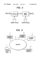
- FIG. 6 is a view showing the structure of a network system according to one embodiment of the present invention.
- FIG. 7 is a block diagram showing the structure of a client PC 1 shown in FIG. 6;
- FIG. 8 is a flow chart showing a process which is to be performed when a printer B is selected and color data is output by the selected printer B, in a case where the color data is printed on the basis of an application software 19 in a network system;
- FIG. 9 is a view showing a display dialog-box in a step S 103 of FIG. 8;
- FIG. 10 is a flow chart showing the detailed process in a step S 105 of FIG. 8;
- FIG. 11 is a flow chart showing the detailed process in a step S 200 of FIG. 10;
- FIG. 12 is a flow chart showing the detailed process in the step S 200 of FIG. 10.
- FIG. 13 is a flow chart showing the detailed process in the step S 200 of FIG. 10 .
- FIG. 6 is a view showing the structure of a network system according to one embodiment of the present invention.
- the network system is composed of a client personal computer (PC) 1 , a network server 2 , network printers 4 , 5 and 6 , and a network 3 .
- the client PC 1 , the server 2 and the printers 4 to 6 are all connected to the network 3 .
- the network server 4 has a CPU (central processing unit), a RAM (random access memory), a hard disk and the like necessary for an image process and a printing process, and has a communication function necessary for network communication.
- the network printers 4 , 5 and 6 correspond to printers A, B and C, respectively.
- FIG. 7 is a block diagram showing the structure of the client PC 1 shown in FIG. 6 .
- the client PC 1 has a CPU, a VRAM (video random access memory) and the like necessary for monitor display and image process.
- the client PC 1 has an OS (operating system) 10 for providing a basic function necessary for an operation of a software such as an application software or the like, a monitor 11 , a monitor driver 12 for controlling the monitor display, a network interface (I/F) 13 for connecting the client PC 1 with the network 3 , a CMM 14 being a module for performing a color matching process, a printer driver storage unit 15 for storing printer drivers A, B and C respectively corresponding to the network printers A, B and C, a HDD (hard disk) 16 , a RAM/ROM (random access memory/read-only memory) 17 used as a working memory by the application software and the OS in the color matching process and the like, a profile storage unit 18 for storing printer profiles A, B and C respectively corresponding to the
- FIG. 8 is a flow chart showing the process which is to be performed when the printer B is selected and color data is output by the selected printer B, in a case where the color data is printed based on the application software 19 in the network system.
- a step S 100 the printer driver B for the printer B is selected from the printer driver storage unit 15 , and the printing by the printer B is instructed. Then, the flow advances to a step S 101 .
- step S 101 it is judged whether or not the printing is possible by using the printer B. If judged that the printing of the printer B is possible, the flow advances to a step S 102 to perform the printing by using the printer B. Then, the process terminates.
- step S 101 determines whether the printing is impossible by using the printer B due to mass printing, some error or the like. If judged in the step S 101 that the printing is impossible by using the printer B due to mass printing, some error or the like, the flow advances to a step S 103 .
- step S 103 in order to notify the user that the printing of the printer B is impossible, such a state is displayed on the dialog-box of the application software 19 . Then, the flow advances to a step S 104 .
- step S 104 it is checked whether or not the printing is to be performed by using another network printer.
- the printing by using another network printer is called as substitute printing hereinafter.
- the operation in this step can be realized by displaying “Substitute another printer for printer B?” on the dialog-box such that the user can select “YES” or “NO”. If judged in the step S 104 that the substitute printing is not to be performed, then the process terminates. On the other hand, if judged that the substitute printing is to be performed, the flow advances to a step S 105 to automatically select one of the other network printers (i.e., printer A or C in the present embodiment), and then advances to a step S 106 .
- a step S 105 to automatically select one of the other network printers (i.e., printer A or C in the present embodiment), and then advances to a step S 106 .
- the printing is performed by using the printer selected in the step S 105 , and then the process terminates.
- the monitor profile is given to the CMM 14 as the source profile
- the printer profile corresponding to the printer selected in the step S 105 is given to the CMM 14 as the printer profile
- the color matching process as shown in FIG. 4 is performed.
- the image data subjected to the color matching process is given to the printer driver corresponding to the selected printer, whereby the printing process is performed.
- FIG. 9 shows an example of the display dialog-box mentioned in the step S 103 of FIG. 8 .
- the dialog-box in FIG. 9 displays that the printing by the printer B is impossible, thereby asking the user whether he intends to continue the printing by using another printer. In response to such asking, the user may select “YES” if he intends to do so, while the user may select “NO” if he does not intend to do so.
- FIG. 10 is a flow chart showing the details of the automatic selection process in the step S 105 of FIG. 8 .
- a step S 200 the gamut size of the printer A is compared with that of the printer B to check the area common to the printers A and B, and the flow advances to a step S 201 .
- step S 201 the result checked in the step S 200 is stored as C BA (constant), and the flow advances to a step S 202 .
- step S 202 the gamut size of the printer B is compared with that of the printer C to check the area common to the printers B and C, and the flow advances to a step S 203 .
- step S 203 the result checked in the step S 202 is stored as C BC (constant), and the flow advances to a step S 204 .
- step S 204 the values of the constants C BA and C BC are compared with each other.
- the flow advances to a step S 205 to select the printer C as the printer substituted for the printer B, and the flow further advances to a step S 208 .
- the judgment standard in the step S 204 corresponds to priority order of the printers previously set by the user (e.g., network manager).
- step S 204 if the value of the constant C BC is equal to that of the constant C BA , this means that the common area of the printers C and B is identical with that of the printers A and B. Therefore, it is possible to judge from the viewpoint of color reproduction that each of the printers C and A is suitable for the substitute printer. Then, the flow advances to a step S 206 to select the printer A as the printer substituted for the printer B, and the flow further advances to the step S 208 .
- step S 204 if the value of the constant C BC is smaller than that of the constant C BA , this means that the common area of the printers A and B is larger than that of the printers C and B. Therefore, it is possible to judge from the viewpoint of color reproduction that the printer A is suitable for the substitute printer rather than the printer C. Then, the flow advances to a step S 207 to select the printer A as the printer substituted for the printer B, and the flow further advances to the step S 208 .
- step S 208 the printer driver selected in the step S 205 , S 206 or S 207 is selected, and then the process terminates.
- the gamut data in the printer profile for the printer B is compared with that for the other printers, and the printer of which area in the gamut common to that of the printer B is largest is selected, whereby it is possible to select the optimum substitute printer from the viewpoint of color reproduction.
- FIGS. 11, 12 and 13 are flow charts showing the details of the process in the step S 200 of FIG. 10 . It should be noted that, if the printer A is replaced with the printer C in the step S 202 of FIG. 10, the process of the step S 202 becomes identical with that of the step S 200 .
- a step S 300 the number of grids of the gamut data stored in the gamut tag of the printer profile for the printer B is compared with the number of grids of the gamut data stored in the gamut tag of the printer profile for the printer A, and the flow advances to a step S 301 .
- step S 301 if the number of grids for the printer B is equal to the number of grids for the printer A, the flow advances to a step S 303 .
- the flow advances to a step S 302 to convert the gamut data in the printer profile for the printer A in accordance with the number of grids of the gamut data for the printer B, and the flow further advances to the step S 303 .
- step S 302 it is possible to make the number of grids of the gamut data for the printer A coincident with the number of grids of the gamut data for the printer B, whereby it is possible to effectively perform following comparison processes. Further, since the number of grids of the substitute output device is made coincident with the number of grids of the output device indicated in the step S 100 , it is possible to effectively perform the comparison processes from the viewpoint of both color reproduction and processing speed.
- step S 303 the number:of grids of the gamut data for the printer B is set as a constant “k”, and the flow advances to a step S 304 .
- step S 304 “0” is set to constants “l”, “m”, “n” and “j” respectively, and the flow advances to a step S 305 .
- step S 305 the output value stored for the grids (l, m, n) in the gamut data for the printer B is set as “OutB”, and the flow advances to a step S 306 .
- step S 306 the output value stored for the grids (l, m, n) in the gamut data for the printer A is set as “OutA”, and the flow advances to a step S 307 .
- step S 307 AND (logical product) of the values “OutB” and “OutA” is obtained, and the obtained value is stored as the value “Out”.
- step S 308 the value “Out” is checked. If the value “Out” is not “ON”, the flow advances to a step S 310 . On the other hand, if the value “Out” is “ON”, the flow advances to a step S 309 to perform increment of the constant “j” by one, and the flow advances to the step S 310 .
- step S 310 the value of the constant “l” is checked.
- step S 311 if the value of the constant “l” is different from the value of the constant “k”, the flow advances to a step S 311 to perform increment of the constant “l” by one and then returns to the step S 305 .
- step S 312 if the value of the constant “l” is equal to the value of the constant “k”, the flow advances to a step S 312 to check the value of the constant “m”. If the value of the constant “m” is different from the value of the constant “k”, the flow advances to a step S 313 to perform increment of the constant “m” by one and then returns to the step S 305 .
- step S 314 If the value of the constant “m” is equal to the value of the constant “k”, the flow advances to a step S 314 to check the value of the constant “n”. Then, if the value of the constant “n” is different from the value of the constant “k”, the flow advances to a step S 315 to perform increment of the value “n” by one and then returns to the step S 305 . On the other hand, if the value of the constant “n” is equal to the value of the constant “k”, the flow advances to a step S 316 to set the value of the constant “j” as the result of the entire output value check. Then, the process terminates.
- any one of the plural color printers in the network system is selected to perform the outputting, if it is impossible for the selected printer to perform the printing, then it is possible to automatically select the substitute output device on the basis of the gamut data important in the color reproduction. Therefore, by using the substitute output device, it is possible to output the image having the tint close to that of the image output by the selected printer.
- the gamut data stored in the profile to be used in the conventional color matching process is used, it is possible to easily realize the function of selecting the substitute output device even in the conventional system.
- the first embodiment supposes the small-scale network system as shown in FIG. 6 .
- the second embodiment is a modification derived from the first embodiment. That is, the second embodiment to be explained hereinafter supposes a large-scale network system. In the large-scale network system, there is a possibility that a number of printers are connected thereto. Moreover, there is a possibility that some of these printers are put at considerably distant positions.
- the gamut of the printer indicated in the step S 100 is compared with the gamuts of the printers within the group previously set by the user, to select the optimum substitute printer.
- the printers are grouped according to a printing system such as an electrophotographic system, an inkjet system or the like. It has been known that, if the printing system varies, then the color reproducibility also varies. Therefore, even if the gamut of one printer is common to that of the other printer, it is thought that a tint or hue of the image printed by one printer is different from that of the image printed by the other printer. For this reason, by previously grouping the plural printers according to the printing system, it is possible to automatically select the substitute printer in consideration of not only the gamut but also the printing system, thereby guaranteeing high-precision color reproducibility in the substitute printing.
- a printing system such as an electrophotographic system, an inkjet system or the like.
- the comparison process for the color gamuts is performed every time the substitute output device is selected.
- the present invention is not limited to this. That is, it is possible to register the result obtained in one comparison process and then select the substitute output device on the basis of the registered result.
- the above substitute output device selecting process to a case where the substitute output device is selected as it attaches importance to the color reproducibility. Further, for example, it is possible to apply this selecting process to not only the above case where it is impossible for the indicated output device to perform the outputting but also to other processes such as a proof process and the like.
- the present invention also includes a case where, in order to realize the functions explained in, e.g., FIGS. 8 to 13 , program codes of software for realizing the functions of the above embodiments are supplied to a computer (CPU or MPU) in an apparatus or a system, and thus the computer in the apparatus or the system operates the various devices according to the supplied program codes.
- a computer CPU or MPU
- the program codes themselves realize the functions of the above embodiments. Therefore, the program codes themselves and a means for supplying the program codes to the computer (e.g., storage medium storing program codes) constitute the present invention.
- the storage medium for storing the program codes it is possible to use, e.g., a floppy disk, a hard disk, an optical disk, a magneto-optical disk, a CD-ROM, a magnetic tape, a non-volatile memory card, a ROM and the like.
- the present invention also includes a case where, after the supplied program codes are stored in a memory of a function expansion board in the computer or a memory of a function expansion unit connected to the computer, a CPU or the like provided in the function expansion board or the function expansion unit performs a part or all of the actual processes on the basis of instructions of the program codes, and thus the functions of the above embodiments are realized by such the processes.
Landscapes
- Engineering & Computer Science (AREA)
- Theoretical Computer Science (AREA)
- Human Computer Interaction (AREA)
- Physics & Mathematics (AREA)
- General Engineering & Computer Science (AREA)
- General Physics & Mathematics (AREA)
- Quality & Reliability (AREA)
- Color Image Communication Systems (AREA)
- Facsimile Image Signal Circuits (AREA)
Applications Claiming Priority (2)
| Application Number | Priority Date | Filing Date | Title |
|---|---|---|---|
| JP11689798A JPH11305970A (ja) | 1998-04-27 | 1998-04-27 | 画像処理装置、方法および記録媒体 |
| JP10-116897 | 1998-04-27 |
Publications (1)
| Publication Number | Publication Date |
|---|---|
| US6563944B1 true US6563944B1 (en) | 2003-05-13 |
Family
ID=14698358
Family Applications (1)
| Application Number | Title | Priority Date | Filing Date |
|---|---|---|---|
| US09/296,625 Expired - Fee Related US6563944B1 (en) | 1998-04-27 | 1999-04-23 | Image processing apparatus and method that automatically selects a substitute output device |
Country Status (2)
| Country | Link |
|---|---|
| US (1) | US6563944B1 (enExample) |
| JP (1) | JPH11305970A (enExample) |
Cited By (19)
| Publication number | Priority date | Publication date | Assignee | Title |
|---|---|---|---|---|
| US20020041708A1 (en) * | 2000-08-31 | 2002-04-11 | Pettitt Gregory S. | Automated color matching for tiled projection system |
| US20020154335A1 (en) * | 2001-04-06 | 2002-10-24 | Tatsuo Matoba | Printing system, print managing device and method, computer program and computer-readable storing medium |
| US20020163666A1 (en) * | 2000-04-07 | 2002-11-07 | Fumihiko Iwata | Control of distributed printers |
| US20020163570A1 (en) * | 2001-05-07 | 2002-11-07 | Phillips Quintin T. | System and methods for adjusting color gamut based on printer consumable condition |
| US20020163665A1 (en) * | 2000-04-07 | 2002-11-07 | Fumihiko Iwata | Control of decentralized printing by printers |
| US20030081242A1 (en) * | 2001-10-31 | 2003-05-01 | Simpson Shell S. | Printing system |
| US20030103233A1 (en) * | 2001-12-05 | 2003-06-05 | Christian Struble | Methods and apparatus for retrieving information for imaging apparatus |
| US20030128376A1 (en) * | 2002-01-04 | 2003-07-10 | Simpson Shell Sterling | System and method for color gamut inadequacy notification |
| US20040136020A1 (en) * | 2002-10-31 | 2004-07-15 | Canon Kabushiki Kaisha | Image processing appartus and method |
| US20040208500A1 (en) * | 2003-04-15 | 2004-10-21 | Fuji Xerox Co., Ltd. | Print service support system |
| US20050024698A1 (en) * | 2003-06-23 | 2005-02-03 | Logo Beteiligungsges, Mbh | Process for the output of a digital document on an output device |
| US20060224939A1 (en) * | 2005-04-01 | 2006-10-05 | Canon Kabushiki Kaisha | Document management system, document management method, and program |
| US20080068630A1 (en) * | 2002-06-28 | 2008-03-20 | Canon Kabkushiki Kaisha | Image processing apparatus and its method, and control method |
| US20080115059A1 (en) * | 2006-11-14 | 2008-05-15 | Canon Kabushiki Kaisha | Information processing apparatus, method of controlling same, program and storage medium |
| US20080137137A1 (en) * | 2006-12-11 | 2008-06-12 | Canon Kabushiki Kaisha | Image processing system configured to perform image processing with a plurality of devices operating in cooperation with each other |
| US20080180704A1 (en) * | 2007-01-12 | 2008-07-31 | Sharp Kabushiki Kaisha | Image document creation device, method for printing image document, program for printing image document, and recording medium |
| US20080212113A1 (en) * | 2007-01-09 | 2008-09-04 | Samsung Electronics Co., Ltd. | Host device having a printer driver and control method of the printer driver |
| US20140032743A1 (en) * | 2012-07-30 | 2014-01-30 | James S. Hiscock | Selecting equipment associated with provider entities for a client request |
| US20190258437A1 (en) * | 2018-02-20 | 2019-08-22 | Ricoh Company, Ltd. | Dynamic color matching between printers and print jobs |
Families Citing this family (3)
| Publication number | Priority date | Publication date | Assignee | Title |
|---|---|---|---|---|
| JP3638228B2 (ja) | 1999-06-11 | 2005-04-13 | コニカミノルタビジネステクノロジーズ株式会社 | 画像出力システム |
| JP4882527B2 (ja) * | 2006-06-09 | 2012-02-22 | 富士ゼロックス株式会社 | 画像処理システム及び画像処理装置 |
| JP5929161B2 (ja) * | 2011-12-21 | 2016-06-01 | 株式会社リコー | 画像処理装置、画像出力システム、画像処理制御方法及び画像処理制御プログラム |
Citations (11)
| Publication number | Priority date | Publication date | Assignee | Title |
|---|---|---|---|---|
| US4941038A (en) * | 1987-05-11 | 1990-07-10 | The Mead Corporation | Method for color image processing |
| US5268754A (en) * | 1991-03-01 | 1993-12-07 | Barco Graphics N.V. | Method and a device for converting a color coordinate set |
| US5323249A (en) * | 1993-01-12 | 1994-06-21 | E. I. Du Pont De Nemours And Company | Method for reproducing color images having one color gamut with a device having a different color gamut |
| US5384901A (en) * | 1992-10-22 | 1995-01-24 | Xerox Corporation | Method of rendering a color image for an output medium from symbolic image data |
| US5402361A (en) * | 1991-04-18 | 1995-03-28 | X-Rite, Incorporated | Apparatus for method for logging, storing, and redirection of process related non-densitometric data generated by color processing equipment for use by an off site host computer |
| US5668890A (en) * | 1992-04-06 | 1997-09-16 | Linotype-Hell Ag | Method and apparatus for the automatic analysis of density range, color cast, and gradation of image originals on the BaSis of image values transformed from a first color space into a second color space |
| US5754184A (en) * | 1993-01-06 | 1998-05-19 | Eastman Kodak Company | Digital color system and method which provides a visual match across different input and output viewing conditions |
| US5835624A (en) * | 1995-10-20 | 1998-11-10 | Brother Kogyo Kabushiki Kaisha | Color conversion device |
| US5907667A (en) * | 1996-01-25 | 1999-05-25 | Dainippon Screen Manufacturing Co., Ltd. | Image matching with equivalent sharpness enhancement |
| US5907415A (en) * | 1995-12-15 | 1999-05-25 | Canon Kabushiki Kaisha | Image processing apparatus with color gamut dependent on color mode |
| US6204939B1 (en) * | 1998-03-30 | 2001-03-20 | Seiko Epson Corporation | Color matching accuracy inside and outside the gamut |
-
1998
- 1998-04-27 JP JP11689798A patent/JPH11305970A/ja active Pending
-
1999
- 1999-04-23 US US09/296,625 patent/US6563944B1/en not_active Expired - Fee Related
Patent Citations (11)
| Publication number | Priority date | Publication date | Assignee | Title |
|---|---|---|---|---|
| US4941038A (en) * | 1987-05-11 | 1990-07-10 | The Mead Corporation | Method for color image processing |
| US5268754A (en) * | 1991-03-01 | 1993-12-07 | Barco Graphics N.V. | Method and a device for converting a color coordinate set |
| US5402361A (en) * | 1991-04-18 | 1995-03-28 | X-Rite, Incorporated | Apparatus for method for logging, storing, and redirection of process related non-densitometric data generated by color processing equipment for use by an off site host computer |
| US5668890A (en) * | 1992-04-06 | 1997-09-16 | Linotype-Hell Ag | Method and apparatus for the automatic analysis of density range, color cast, and gradation of image originals on the BaSis of image values transformed from a first color space into a second color space |
| US5384901A (en) * | 1992-10-22 | 1995-01-24 | Xerox Corporation | Method of rendering a color image for an output medium from symbolic image data |
| US5754184A (en) * | 1993-01-06 | 1998-05-19 | Eastman Kodak Company | Digital color system and method which provides a visual match across different input and output viewing conditions |
| US5323249A (en) * | 1993-01-12 | 1994-06-21 | E. I. Du Pont De Nemours And Company | Method for reproducing color images having one color gamut with a device having a different color gamut |
| US5835624A (en) * | 1995-10-20 | 1998-11-10 | Brother Kogyo Kabushiki Kaisha | Color conversion device |
| US5907415A (en) * | 1995-12-15 | 1999-05-25 | Canon Kabushiki Kaisha | Image processing apparatus with color gamut dependent on color mode |
| US5907667A (en) * | 1996-01-25 | 1999-05-25 | Dainippon Screen Manufacturing Co., Ltd. | Image matching with equivalent sharpness enhancement |
| US6204939B1 (en) * | 1998-03-30 | 2001-03-20 | Seiko Epson Corporation | Color matching accuracy inside and outside the gamut |
Cited By (36)
| Publication number | Priority date | Publication date | Assignee | Title |
|---|---|---|---|---|
| US7167260B2 (en) * | 2000-04-07 | 2007-01-23 | Seiko Epson Corporation | Control of distributed printers using virtual printer driver execute module |
| US20020163666A1 (en) * | 2000-04-07 | 2002-11-07 | Fumihiko Iwata | Control of distributed printers |
| US20020163665A1 (en) * | 2000-04-07 | 2002-11-07 | Fumihiko Iwata | Control of decentralized printing by printers |
| US7173718B2 (en) * | 2000-04-07 | 2007-02-06 | Seiko Epson Corporation | Control of distributed printing using data output control module |
| US7515746B2 (en) * | 2000-08-31 | 2009-04-07 | Texas Instruments Incorporated | Automated color matching for tiled projection system |
| US20020041708A1 (en) * | 2000-08-31 | 2002-04-11 | Pettitt Gregory S. | Automated color matching for tiled projection system |
| US20020154335A1 (en) * | 2001-04-06 | 2002-10-24 | Tatsuo Matoba | Printing system, print managing device and method, computer program and computer-readable storing medium |
| US7170623B2 (en) * | 2001-04-06 | 2007-01-30 | Canon Kabushiki Kaisha | Transferring print data between print management apparatuses |
| US20020163570A1 (en) * | 2001-05-07 | 2002-11-07 | Phillips Quintin T. | System and methods for adjusting color gamut based on printer consumable condition |
| US20030081242A1 (en) * | 2001-10-31 | 2003-05-01 | Simpson Shell S. | Printing system |
| US20030103233A1 (en) * | 2001-12-05 | 2003-06-05 | Christian Struble | Methods and apparatus for retrieving information for imaging apparatus |
| US20030128376A1 (en) * | 2002-01-04 | 2003-07-10 | Simpson Shell Sterling | System and method for color gamut inadequacy notification |
| US7420704B2 (en) * | 2002-01-04 | 2008-09-02 | Hewlett-Packard Development Company, L.L.P. | System and method for color gamut inadequacy notification |
| US20100328693A1 (en) * | 2002-06-28 | 2010-12-30 | Canon Kabushiki Kaisha | Image processing apparatus and its method, and control method |
| US20080068630A1 (en) * | 2002-06-28 | 2008-03-20 | Canon Kabkushiki Kaisha | Image processing apparatus and its method, and control method |
| US8203758B2 (en) | 2002-06-28 | 2012-06-19 | Canon Kabushiki Kaisha | Image processing apparatus and its method, and control method |
| US7880931B2 (en) | 2002-06-28 | 2011-02-01 | Canon Kabushiki Kaisha | Image processing apparatus and its method, and control method |
| US7554694B2 (en) * | 2002-06-28 | 2009-06-30 | Canon Kabushiki Kaisha | Image processing apparatus and its method, and control method |
| US20090244557A1 (en) * | 2002-06-28 | 2009-10-01 | Canon Kabushiki Kaisha | Image processing apparatus and its method, and control method |
| US20040136020A1 (en) * | 2002-10-31 | 2004-07-15 | Canon Kabushiki Kaisha | Image processing appartus and method |
| US20040208500A1 (en) * | 2003-04-15 | 2004-10-21 | Fuji Xerox Co., Ltd. | Print service support system |
| US20050024698A1 (en) * | 2003-06-23 | 2005-02-03 | Logo Beteiligungsges, Mbh | Process for the output of a digital document on an output device |
| US20060224939A1 (en) * | 2005-04-01 | 2006-10-05 | Canon Kabushiki Kaisha | Document management system, document management method, and program |
| US7777906B2 (en) * | 2005-04-01 | 2010-08-17 | Canon Kabushiki Kaisha | Document management system, document management method, and program |
| US7904816B2 (en) * | 2006-11-14 | 2011-03-08 | Canon Kabushiki Kaisha | Information processing apparatus, method of controlling same, program and storage medium |
| US20110126112A1 (en) * | 2006-11-14 | 2011-05-26 | Canon Kabushiki Kaisha | Information processing apparatus, method of controlling same, program and storage medium |
| US20080115059A1 (en) * | 2006-11-14 | 2008-05-15 | Canon Kabushiki Kaisha | Information processing apparatus, method of controlling same, program and storage medium |
| US8769411B2 (en) | 2006-11-14 | 2014-07-01 | Canon Kabushiki Kaisha | Information processing apparatus, method of controlling same, program and storage medium |
| US20080137137A1 (en) * | 2006-12-11 | 2008-06-12 | Canon Kabushiki Kaisha | Image processing system configured to perform image processing with a plurality of devices operating in cooperation with each other |
| US8508789B2 (en) | 2006-12-11 | 2013-08-13 | Canon Kabushiki Kaisha | Determining a degree of fit between an image data input device and an image data output device |
| US20080212113A1 (en) * | 2007-01-09 | 2008-09-04 | Samsung Electronics Co., Ltd. | Host device having a printer driver and control method of the printer driver |
| US20080180704A1 (en) * | 2007-01-12 | 2008-07-31 | Sharp Kabushiki Kaisha | Image document creation device, method for printing image document, program for printing image document, and recording medium |
| US7933042B2 (en) * | 2007-01-12 | 2011-04-26 | Sharp Kabushiki Kaisha | Image document creation device, method for printing image document, program for printing image document, and recording medium |
| US20140032743A1 (en) * | 2012-07-30 | 2014-01-30 | James S. Hiscock | Selecting equipment associated with provider entities for a client request |
| US20190258437A1 (en) * | 2018-02-20 | 2019-08-22 | Ricoh Company, Ltd. | Dynamic color matching between printers and print jobs |
| US10419645B2 (en) * | 2018-02-20 | 2019-09-17 | Ricoh Company, Ltd. | Dynamic color matching between printers and print jobs |
Also Published As
| Publication number | Publication date |
|---|---|
| JPH11305970A (ja) | 1999-11-05 |
Similar Documents
| Publication | Publication Date | Title |
|---|---|---|
| US6563944B1 (en) | Image processing apparatus and method that automatically selects a substitute output device | |
| US6549654B1 (en) | Image processing method and apparatus and storage medium storing processes of executing the method | |
| US5960162A (en) | Image processing apparatus which converts multi-value density data and outputs the converted data | |
| EP0679019B1 (en) | Image processing apparatus and method | |
| EP0706285B1 (en) | Image processing apparatus and method therefor | |
| EP0881826B1 (en) | Image processing method, and image processing apparatus | |
| EP0700198B1 (en) | System for correcting color images using tetrahedral interpolation over a hexagonal lattice | |
| US5572632A (en) | Universal frame buffer for a rendering device | |
| US7619773B2 (en) | Color management system using measured device data | |
| US7239425B2 (en) | Color processing method and apparatus for generating a conversion condition for converting data in a device independent color space into data in a device dependent color space | |
| JP2000196909A (ja) | ルックアップテ―ブルの精度の改良方法 | |
| US7813001B2 (en) | Color image processing method, color image processor and storage medium | |
| US7366346B2 (en) | Color descriptor data structure | |
| US7126718B1 (en) | Adjustment of color appearance models | |
| US20050253866A1 (en) | Method and apparatus for creating profile | |
| US5915075A (en) | Image processing apparatus for converting input color chart data into color data for an output device | |
| US20060028665A1 (en) | Method of creating color conversion table and image processing apparatus | |
| JP3915879B2 (ja) | カラーデータ処理装置、カラーデータ処理方法、及び記憶媒体 | |
| JPH0795427A (ja) | 画像処理方法及び装置 | |
| JP3854644B2 (ja) | 画像処理方法及び装置 | |
| US7145575B2 (en) | Color image processing device, color image processing method, recording medium, and program | |
| JP2001197323A (ja) | プロファイル作成方法およびプロファイル作成装置 | |
| JP2004112270A (ja) | 色変換テーブル作成方法および色変換テーブル作成装置並びにプログラム | |
| GB2426657A (en) | Colour space conversion | |
| JP4095436B2 (ja) | カラー画像処理装置、カラー画像処理方法、記憶媒体、プログラム |
Legal Events
| Date | Code | Title | Description |
|---|---|---|---|
| AS | Assignment |
Owner name: CANON KABUSHIKI KAISHA, JAPAN Free format text: ASSIGNMENT OF ASSIGNORS INTEREST;ASSIGNOR:KUMADA, SHUICHI;REEL/FRAME:010080/0913 Effective date: 19990519 |
|
| FEPP | Fee payment procedure |
Free format text: PAYOR NUMBER ASSIGNED (ORIGINAL EVENT CODE: ASPN); ENTITY STATUS OF PATENT OWNER: LARGE ENTITY |
|
| FPAY | Fee payment |
Year of fee payment: 4 |
|
| FPAY | Fee payment |
Year of fee payment: 8 |
|
| REMI | Maintenance fee reminder mailed | ||
| LAPS | Lapse for failure to pay maintenance fees | ||
| STCH | Information on status: patent discontinuation |
Free format text: PATENT EXPIRED DUE TO NONPAYMENT OF MAINTENANCE FEES UNDER 37 CFR 1.362 |
|
| FP | Lapsed due to failure to pay maintenance fee |
Effective date: 20150513 |