US6559448B1 - Passive infrared detector - Google Patents
Passive infrared detector Download PDFInfo
- Publication number
- US6559448B1 US6559448B1 US09/663,494 US66349400A US6559448B1 US 6559448 B1 US6559448 B1 US 6559448B1 US 66349400 A US66349400 A US 66349400A US 6559448 B1 US6559448 B1 US 6559448B1
- Authority
- US
- United States
- Prior art keywords
- surveillance
- sub
- row
- subzones
- focusing
- Prior art date
- Legal status (The legal status is an assumption and is not a legal conclusion. Google has not performed a legal analysis and makes no representation as to the accuracy of the status listed.)
- Expired - Lifetime, expires
Links
- 241001465754 Metazoa Species 0.000 claims abstract description 19
- 241000282414 Homo sapiens Species 0.000 claims abstract description 18
- 230000003247 decreasing effect Effects 0.000 claims abstract description 3
- 230000005855 radiation Effects 0.000 claims description 10
- 241000791900 Selene vomer Species 0.000 claims description 9
- 230000035945 sensitivity Effects 0.000 claims description 4
- 230000003287 optical effect Effects 0.000 claims description 3
- 241000282472 Canis lupus familiaris Species 0.000 description 20
- 238000001514 detection method Methods 0.000 description 5
- 238000001746 injection moulding Methods 0.000 description 4
- 230000036039 immunity Effects 0.000 description 3
- 238000004519 manufacturing process Methods 0.000 description 3
- 230000001960 triggered effect Effects 0.000 description 3
- 241000202252 Cerberus Species 0.000 description 2
- 238000012423 maintenance Methods 0.000 description 2
- 239000007787 solid Substances 0.000 description 2
- 230000009471 action Effects 0.000 description 1
- 230000008901 benefit Effects 0.000 description 1
- 230000037396 body weight Effects 0.000 description 1
- 238000010586 diagram Methods 0.000 description 1
- 230000004069 differentiation Effects 0.000 description 1
- 230000009977 dual effect Effects 0.000 description 1
- 238000005516 engineering process Methods 0.000 description 1
- 208000024798 heartburn Diseases 0.000 description 1
- 230000009467 reduction Effects 0.000 description 1
- 230000004044 response Effects 0.000 description 1
Images


Classifications
-
- G—PHYSICS
- G08—SIGNALLING
- G08B—SIGNALLING OR CALLING SYSTEMS; ORDER TELEGRAPHS; ALARM SYSTEMS
- G08B13/00—Burglar, theft or intruder alarms
- G08B13/18—Actuation by interference with heat, light, or radiation of shorter wavelength; Actuation by intruding sources of heat, light, or radiation of shorter wavelength
- G08B13/189—Actuation by interference with heat, light, or radiation of shorter wavelength; Actuation by intruding sources of heat, light, or radiation of shorter wavelength using passive radiation detection systems
- G08B13/19—Actuation by interference with heat, light, or radiation of shorter wavelength; Actuation by intruding sources of heat, light, or radiation of shorter wavelength using passive radiation detection systems using infrared-radiation detection systems
- G08B13/193—Actuation by interference with heat, light, or radiation of shorter wavelength; Actuation by intruding sources of heat, light, or radiation of shorter wavelength using passive radiation detection systems using infrared-radiation detection systems using focusing means
Definitions
- the present invention relates to a passive infrared detector having a heat-sensitive sensor and a focusing device for focusing thermal rays incident from the room under surveillance incident on the detector on to the sensor, and more particularly the focusing device having focusing elements for the surveillance regions having different positions in the room under surveillance.
- Passive infrared detectors of this type have been known for years and are widespread. They serve, in particular, to detect the presence of unauthorized individuals into the room under surveillance by detecting the typical infrared radiation that is emitted by individuals which is guided by a focusing element onto the sensor.
- Known focusing devices include Fresnel lenses that are incorporated into the entrance window for the infrared radiation disposed on the front of the detector casing (in this connection, see, for example, EP--A-0 559 110) or a mirror that is disposed in the interior of the detector casing and that comprises individual reflectors (in this connection, see U.S. Pat. No. 4,880,980).
- a plurality of rows of reflectors is provided, each row corresponding to a particular surveillance zone, for example, remote zone, middle zone, near zone and look-down zone.
- each surveillance zone is divided into surveillance regions and the room to be kept under surveillance is thus covered in a fanshaped manner by surveillance regions emanating from the detector. Consequently, each reflector determines a surveillance region with a defined position in the room under surveillance. As soon as an object emitting thermal radiation intrudes into the room, the sensor detects the thermal radiation emitted by the object. The detection is most reliable if the object moves transversely with respect to the surveillance region.
- passive infrared detectors of the present generation can detect intruders within the active region of the detector very reliably, they are not generally able to distinguish human beings from fairly large domestic animals, such as, for example, dogs, and emit an alarm even when an animal is detected. The longer these false alarms are, the less they are tolerated and the protection of passive infrared detectors, against false alarms triggered by domestic animals moving through the room under surveillance, described as domestic animal immunity, has recently developed as an essential requirement of the market. This feature is increasingly being demanded even of passive infrared detectors in the lower price segment of the market.
- the focusing device is formed by a lens arrangement having a plurality of differently aligned, non-overlapping fields of view or surveillance regions that extend in a fan-shaped manner from the lens arrangement into the room under surveillance. These surveillance regions are staggered vertically, approximately equally such that relatively large gaps are formed between the individual regions.
- An intruder having a certain minimum height will always cross at least one surveillance region and consequently always generate a sensor signal.
- An intruder below the minimum height will cross surveillance regions and gaps only alternately and in the latter case will not generate a sensor signal. In this way, a human being, if he moves through the room under surveillance will generate a steady sensor signal having approximately constant amplitude, whereas an animal triggers a pulse-shaped signal of substantially lower maximum amplitude.
- the object of the invention is therefore to provide a passive infrared detector of the type mentioned at the outset whose ability to distinguish between human beings and animals is substantially improved.
- each focusing element comprises a number of sub-elements so that the surveillance regions are split up vertically into subzones having slightly different elevation and in that the human beings are distinguished from animals on the basis of the amplitude of the sensor signal.
- the achievement according to the invention has the advantage that even a very large animal is always reliably distinguished from a human being provided its height is less than that of an human being.
- a human being walking upright still always crosses a plurality of subzones of remote and middle zones, or middle and near zones, etc., and therefore triggers a much greater sensor signal than an animal of smaller height.
- the latter will cross markedly fewer subzones and generate a markedly reduced sensor signal.
- a dog of normal height will cross one subzone or at most two, but this only partly, and will consequently trigger a signal reduced to one half or one third compared with the detector described in U.S. Pat. No. 4,880,980.
- a first embodiment of the passive infrared detector according to the invention is characterized in that the elevation of the sub-elements is chosen so that, in the majority of the surveillance regions, at most only an insignificant overlapping of the subzones occurs.
- a second embodiment is characterized in that the number of sub-elements and, correspondingly, the number of subzones increases with decreasing radial distance of the respective surveillance region from the detector.
- a third embodiment of the detector according to the invention is characterized in that the subzones are arranged in layers in a stack-like manner on top of one another and that the chosen layering is such that a sequence of dense curtains is produced and the sensitivity in the individual subzones being approximately equal. The latter is achieved by avoiding overlapping of the individual subzones.
- a fourth embodiment of the detector according to the invention is characterized in that the weighting of the individual sub-elements, in particular their optical aperture and area, is chosen in such a way that an animal that is moving transversely with respect to the coverage pattern formed by the surveillance region and that is of any optional size delivers an approximately equally small signal for all distances between animal and detector.
- the animal is a hair-coated dog with a length of 80 cm and a height of 60 cm.
- a fifth embodiment of the detector according to the invention is characterized in that the focusing device is formed by a mirror arrangement having reflectors forming the focusing elements and each reflector is split up into sub-areas.
- the sub-areas which are, as a rule, paraboloid sub-areas, can be combined to form groups of mirror regions that are joined together for the production of the injection-molding tool for the mirror arrangement, resulting in a less expensive production and maintenance of the injection-molding tool.
- a sixth embodiment is characterized in that the mirror arrangement has a first reflector row for a remote zone, a second reflector row for a middle zone, a third reflector zone for a near zone and a fourth reflector row for a look-down zone and in that the reflectors of the first row and the reflectors of the second row are each split up into three sub-areas and the reflectors of the third row are split up into four sub-areas and the reflector of the fourth row is split up into five sub-areas.
- a further embodiment of the detector according to the invention is characterized in that the sensor has four sensor elements that are combined in pairs and that form two independent channels and in that the respective signal is evaluated in each channel.
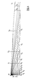
- FIG. 1 shows a diagrammatic front view of the focusing of a detector according to the invention formed by a mirror arrangement
- FIG. 2 shows a section along the line II—II in FIG. 1;
- FIG. 3 shows a plan view of the coverage pattern produced by the mirror arrangement in FIGS. 1 and 2;
- FIG. 4 shows a side view of the coverage pattern in FIG. 3;
- FIG. 5 shows a schematic view of a quad element pyrosensor having four flakes F 1 to F 4 , wherein the upper flakes F 1 , F 2 and the lower flakes F 1 , F 4 each form a channel;
- FIG. 6 shows a schematic view of long flake pyrosensors F 5 F 6 .
- the mirror arrangement 1 depicted in FIGS. 1 and 2 is a further development of the mirror described in U.S. Pat. No. 4,880,980 that improves the mirror in such a way that it is immune to domestic animals in its active region.
- a Fresnel lens arrangement can also be used as an alternative to the mirror arrangement 1 .
- the mirror arrangement 1 comprises a number of reflectors that are designed so that the room under surveillance is covered in a fan-shaped manner by surveillance regions originating from the detector.
- a plurality of such “fan areas” or surveillance zones are provided that correspond to different distances from the detector.
- Four surveillance zones are distinguished, for example, such as a remote zone, a middle zone, a near zone and a so-called look-down zone, that are covered by four rows of reflectors offset in the vertical direction.
- the rows are row R 1 for the remote zone, row R 2 for the middle zone, row R 3 for the near zone and the row R 4 for the look-down zone, the latter row having only a single reflector.
- the fan-shaped coverage is achieved by mutually offsetting the reflectors of each row in the horizontal direction with the number of reflectors per row increasing with the distance of the respective surveillance zone from the detector to achieve an approximately uniform overlap pattern.
- Each reflector “looks” into a particular solid angle of a particular zone, receives the thermal radiation incident from the corresponding solid angle and focuses it on the heat-sensitive sensor S (FIG. 2 ), which is formed, for example, by a pyrosensor.
- the pyrosensor is preferably a so-called standard dual-element pyrosensor, such as is used, for example, in the passive infrared detectors of Siemens Building Technologies AG, Cerberus Division, formerly Cerberus AG (in this connection, see U.S. Pat. No. 4,880,980).
- the sensor detects thermal radiation emitted by the object, whereupon the detector emits an alarm signal.
- the alarm signal indicates that an object, for example an intruder, is in the room under surveillance.
- the reflector row R 1 for the remote zone comprises seven paraboloidal strip-type reflectors 2 to 8
- the reflector row R 2 for the middle zone comprises five reflectors 9 to 13
- the reflector row R 3 for the near zone comprises three reflectors 14 to 16
- the reflector zone R 4 for the look-down zone comprises a single reflector 17 .
- the individual reflectors do not form a single, uniformly curved area, but have in each case a plurality of sub-areas of different vertical orientation, which splits the assigned surveillance regions up into subzones.
- the junctions between the sub-areas are indicated in FIGS. 1 and 2 by broken horizontal lines or curves.
- the reflectors 2 to 8 for the remote zone and the reflectors 9 to 13 for the middle zone each comprise three sub-areas
- the reflectors 14 to 16 for the near zone each comprise four sub-areas
- the reflector 17 for the look-down zone comprises five sub-areas.
- the individual sub-areas are weighted, i.e., their optical aperture and their area are chosen, in such a way that a dog of a particular size (for example, a hair-covered dog 80 cm long and 60 cm high) moving transversely to the coverage pattern (FIG. 3) produces a signal that is approximately equally small for any distance of the dog from the detector.
- the width of the mirror arrangement is 38 mm at its widest point and the various segments illustrated in FIGS. 1 and 2 are scaled accordingly.
- FIG. 3 shows the coverage pattern of the surveillance regions corresponding to reflectors of the mirror arrangement 1 (FIG. 1) on the floor of the room to be kept under surveillance
- FIG. 4 shows the path of thermal radiation from the surveillance regions to the detector denoted by the reference symbol 18 along the horizontal diagonal of the square shown by a dash-dot line in FIG. 3 and symbolizing a square room under surveillance.
- the surveillance regions along the diagonal correspond to FIG. 1, denoted by 5 1 , 5 2 , 5 3 for the remote zone, 11 1 , 11 2 , 11 3 for the middle zone, 15 1 , 15 2 , 15 3 , 15 4 for the near zone and 17 1 , 17 2 , 17 3 , 17 4 and 17 5 for the look-down zone.
- the surveillance regions have become substantially longer as a result of splitting up into subzones.
- the subzones are arranged in layers in a stack-like manner on top of one another. They are in contact with one another, but have minimal overlap with one another, with the result that no regions of greater sensitivity are produced.
- thermal radiation would, after all, be focused on the sensor from the two respective surveillance regions simultaneously in the overlap region and a correspondingly stronger signal would consequently be produced.
- the mutual non-overlapping relationship does not apply to the surveillance regions 5 1 , 5 2 , 5 3 of the remote zone because overlapping cannot be avoided here owing to the oblique path of the beams.
- the elevation of the sub-areas is chosen so that the surveillance regions overlap in the manner shown in FIG. 4 . Since, however, the remote zone is at a relatively large distance of approximately 12 to 15 m in front of the detector, fluctuations in signal amplitude are not critical here.
- the detector 18 is at a height of 2.25 m above the floor, and the two horizontal lines H and M correspond to a height of 0.6 and 1.8 m, respectively. These lines symbolize the movement of a dog (H) or human being (M) in the surveillance room.
- H dog
- M human being
- a dog crosses only one subzone completely or two subzones partially in the active region of the detector.
- the signal of the sensor S (FIG. 1) is reduced by approximately 50% to 70%.
- an intruder walking upright always crosses a plurality of subzones of the remote and middle zones or middle and near zones or near and look-down zones and consequently produces a many times greater signal than the dog.
- each pair of sensor elements forms a channel, the two channels corresponding in their action to a vertical splitting-up of the surveillance regions.
- even a large dog will never be able to deliver a signal above the detection threshold in the upper channel, with the result that even large dogs cannot trigger a false alarm outside the detector's active region.
- a less expensive, but also less effective, variant compared with the quad-element pyrosensor would be to use longflake pyros.
- the image of a dog of medium size covers markedly more that 50% of the height of the flakes (sensor elements), and the image of a human being walking upright projects far above the height of the flakes, but the part projecting above the flakes does not contribute to the sensor signal. If the height of the flakes were to be doubled, for example, the difference between the signals triggered by a dog and a human being would be substantially larger, which would improve the differentiation.
- the gain factor (increase in the signal of a human being) compared with a dual sensor would be approximately 1.4, but in the case of the quadsensor it would be 2.5 to 3.
Landscapes
- Physics & Mathematics (AREA)
- General Physics & Mathematics (AREA)
- Geophysics And Detection Of Objects (AREA)
- Burglar Alarm Systems (AREA)
- Photometry And Measurement Of Optical Pulse Characteristics (AREA)
- Glass Compositions (AREA)
- Light Guides In General And Applications Therefor (AREA)
Applications Claiming Priority (2)
| Application Number | Priority Date | Filing Date | Title |
|---|---|---|---|
| EP99119496A EP1089245B1 (de) | 1999-10-01 | 1999-10-01 | Passiv-Infrarotmelder |
| EP99119496 | 1999-10-01 |
Publications (1)
| Publication Number | Publication Date |
|---|---|
| US6559448B1 true US6559448B1 (en) | 2003-05-06 |
Family
ID=8239099
Family Applications (1)
| Application Number | Title | Priority Date | Filing Date |
|---|---|---|---|
| US09/663,494 Expired - Lifetime US6559448B1 (en) | 1999-10-01 | 2000-09-18 | Passive infrared detector |
Country Status (8)
| Country | Link |
|---|---|
| US (1) | US6559448B1 (de) |
| EP (1) | EP1089245B1 (de) |
| AT (2) | ATE263403T1 (de) |
| DE (2) | DE59909044D1 (de) |
| DK (1) | DK1089245T3 (de) |
| ES (1) | ES2218927T3 (de) |
| IL (1) | IL138059A (de) |
| PT (1) | PT1089245E (de) |
Cited By (21)
| Publication number | Priority date | Publication date | Assignee | Title |
|---|---|---|---|---|
| US20050231353A1 (en) * | 2004-04-16 | 2005-10-20 | Dipoala William S | Intrusion detection system including over-under passive infrared optics and a microwave transceiver |
| US20050236572A1 (en) * | 2003-03-14 | 2005-10-27 | Micko Eric S | PIR motion sensor |
| EP1656649A2 (de) * | 2003-08-18 | 2006-05-17 | Honeywell International Inc. | Logische pet-immune eindringdetektionsvorrichtung und verfahren |
| WO2007108790A1 (en) * | 2006-03-17 | 2007-09-27 | Adt Security Services, Inc. | Motion detector having asymmetric zones for determining direction of movement and method therefore |
| US20090206161A1 (en) * | 2008-02-12 | 2009-08-20 | Datalogic Scanning, Inc. | Systems and methods for forming a composite image of multiple portions of an object from multiple perspectives |
| US20100163626A1 (en) * | 2008-12-26 | 2010-07-01 | Datalogic Scanning, Inc. | Data reader having compact arrangement for acquisition of multiple views of an object |
| US20100163622A1 (en) * | 2008-02-12 | 2010-07-01 | Datalogic Scanning, Inc. | Monolithic mirror structure for use in a multi-perspective optical code reader |
| US20100163628A1 (en) * | 2008-02-12 | 2010-07-01 | Datalogic Scanning, Inc. | Two-plane optical code reader for acquisition of multiple views an object |
| US20100163627A1 (en) * | 2008-12-26 | 2010-07-01 | Datalogic Scanning, Inc. | Image-based code reader for acquisition of multiple views of an object and methods for employing same |
| US20110118817A1 (en) * | 2009-11-17 | 2011-05-19 | Boston Scientific Scimed, Inc. | Stent delivery system |
| US20120228477A1 (en) * | 2011-03-10 | 2012-09-13 | Siemens Aktiengesellschaft | Detector |
| US8746569B2 (en) | 2008-02-12 | 2014-06-10 | Datalogic ADC, Inc. | Systems and methods for forming a composite image of multiple portions of an object from multiple perspectives |
| US20150359486A1 (en) * | 2014-06-12 | 2015-12-17 | PhysioWave, Inc. | Device and method having automatic user-responsive and user-specific physiological-meter platform |
| US20160021241A1 (en) * | 2014-07-20 | 2016-01-21 | Motorola Mobility Llc | Electronic Device and Method for Detecting Presence and Motion |
| US9255786B2 (en) | 2013-12-09 | 2016-02-09 | Greenwave Systems Pte Ltd | Motion detection |
| US9301412B2 (en) | 2014-06-02 | 2016-03-29 | Greenwave Systems Pte. Ltd. | Dual fixed angle security mount |
| US9611978B2 (en) | 2014-06-02 | 2017-04-04 | Greenwave Systems Pte Ltd | Magnetic mount for security device |
| US9943241B2 (en) | 2014-06-12 | 2018-04-17 | PhysioWave, Inc. | Impedance measurement devices, systems, and methods |
| US10445998B2 (en) | 2016-02-24 | 2019-10-15 | Greenwave Systems Pte. Ltd. | Motion sensor for occupancy detection and intrusion detection |
| US10739190B2 (en) | 2016-02-03 | 2020-08-11 | Greenwave Systems Pte. Ltd. | Motion sensor using linear array of infrared detectors |
| US11080974B2 (en) | 2013-12-13 | 2021-08-03 | Utc Fire & Security Americas Corporation, Inc. | Selective intrusion detection systems |
Citations (7)
| Publication number | Priority date | Publication date | Assignee | Title |
|---|---|---|---|---|
| DE3112529A1 (de) | 1981-03-30 | 1982-11-11 | Fritz Fuss Kg, 7470 Albstadt | Spiegelanordnung fuer eine meldeeinrichtung |
| US4697081A (en) | 1985-02-08 | 1987-09-29 | U.S. Philips Corp. | Infra-red radiation detector devices |
| US4849635A (en) * | 1986-01-24 | 1989-07-18 | Optex Co., Ltd. | Intruder perceiving apparatus by means of infrared detection |
| US4880980A (en) | 1987-08-11 | 1989-11-14 | Cerberus Ag | Intrusion detector |
| US4990783A (en) * | 1988-09-22 | 1991-02-05 | Cerberus A.G. | Range insensitive infrared intrusion detector |
| US5187360A (en) | 1990-11-30 | 1993-02-16 | Combined Optical Industries Limited | Aspheric lens having a plurality of lenslets disposed substantially contiguously in an array |
| US5923250A (en) * | 1997-01-27 | 1999-07-13 | Digital Security Controls Ltd. | Size discriminating dual element PIR detector |
-
1999
- 1999-10-01 DE DE59909044T patent/DE59909044D1/de not_active Expired - Lifetime
- 1999-10-01 PT PT99119496T patent/PT1089245E/pt unknown
- 1999-10-01 AT AT99119496T patent/ATE263403T1/de not_active IP Right Cessation
- 1999-10-01 ES ES99119496T patent/ES2218927T3/es not_active Expired - Lifetime
- 1999-10-01 DK DK99119496T patent/DK1089245T3/da active
- 1999-10-01 EP EP99119496A patent/EP1089245B1/de not_active Expired - Lifetime
-
2000
- 2000-05-29 AT AT00111473T patent/ATE263402T1/de not_active IP Right Cessation
- 2000-05-29 DE DE50005874T patent/DE50005874D1/de not_active Expired - Fee Related
- 2000-08-24 IL IL13805900A patent/IL138059A/en active IP Right Grant
- 2000-09-18 US US09/663,494 patent/US6559448B1/en not_active Expired - Lifetime
Patent Citations (7)
| Publication number | Priority date | Publication date | Assignee | Title |
|---|---|---|---|---|
| DE3112529A1 (de) | 1981-03-30 | 1982-11-11 | Fritz Fuss Kg, 7470 Albstadt | Spiegelanordnung fuer eine meldeeinrichtung |
| US4697081A (en) | 1985-02-08 | 1987-09-29 | U.S. Philips Corp. | Infra-red radiation detector devices |
| US4849635A (en) * | 1986-01-24 | 1989-07-18 | Optex Co., Ltd. | Intruder perceiving apparatus by means of infrared detection |
| US4880980A (en) | 1987-08-11 | 1989-11-14 | Cerberus Ag | Intrusion detector |
| US4990783A (en) * | 1988-09-22 | 1991-02-05 | Cerberus A.G. | Range insensitive infrared intrusion detector |
| US5187360A (en) | 1990-11-30 | 1993-02-16 | Combined Optical Industries Limited | Aspheric lens having a plurality of lenslets disposed substantially contiguously in an array |
| US5923250A (en) * | 1997-01-27 | 1999-07-13 | Digital Security Controls Ltd. | Size discriminating dual element PIR detector |
Cited By (41)
| Publication number | Priority date | Publication date | Assignee | Title |
|---|---|---|---|---|
| US20050236572A1 (en) * | 2003-03-14 | 2005-10-27 | Micko Eric S | PIR motion sensor |
| US7755052B2 (en) * | 2003-03-14 | 2010-07-13 | Suren Systems, Ltd. | PIR motion sensor |
| EP1656649A2 (de) * | 2003-08-18 | 2006-05-17 | Honeywell International Inc. | Logische pet-immune eindringdetektionsvorrichtung und verfahren |
| EP1656649A4 (de) * | 2003-08-18 | 2008-04-02 | Honeywell Int Inc | Logische pet-immune eindringdetektionsvorrichtung und verfahren |
| US20050231353A1 (en) * | 2004-04-16 | 2005-10-20 | Dipoala William S | Intrusion detection system including over-under passive infrared optics and a microwave transceiver |
| US7034675B2 (en) | 2004-04-16 | 2006-04-25 | Robert Bosch Gmbh | Intrusion detection system including over-under passive infrared optics and a microwave transceiver |
| US20100238030A1 (en) * | 2006-03-17 | 2010-09-23 | Adt Security Services, Inc. | Motion detector having asymmetric zones for determining direction of movement and method therefore |
| WO2007108790A1 (en) * | 2006-03-17 | 2007-09-27 | Adt Security Services, Inc. | Motion detector having asymmetric zones for determining direction of movement and method therefore |
| US8009044B2 (en) | 2006-03-17 | 2011-08-30 | Sensormatic Electronics, LLC | Motion detector having asymmetric zones for determining direction of movement and method therefore |
| US8746569B2 (en) | 2008-02-12 | 2014-06-10 | Datalogic ADC, Inc. | Systems and methods for forming a composite image of multiple portions of an object from multiple perspectives |
| US20100163622A1 (en) * | 2008-02-12 | 2010-07-01 | Datalogic Scanning, Inc. | Monolithic mirror structure for use in a multi-perspective optical code reader |
| US20100163628A1 (en) * | 2008-02-12 | 2010-07-01 | Datalogic Scanning, Inc. | Two-plane optical code reader for acquisition of multiple views an object |
| US20090206161A1 (en) * | 2008-02-12 | 2009-08-20 | Datalogic Scanning, Inc. | Systems and methods for forming a composite image of multiple portions of an object from multiple perspectives |
| US8353457B2 (en) * | 2008-02-12 | 2013-01-15 | Datalogic ADC, Inc. | Systems and methods for forming a composite image of multiple portions of an object from multiple perspectives |
| US8678287B2 (en) | 2008-02-12 | 2014-03-25 | Datalogic ADC, Inc. | Two-plane optical code reader for acquisition of multiple views of an object |
| US8608076B2 (en) * | 2008-02-12 | 2013-12-17 | Datalogic ADC, Inc. | Monolithic mirror structure for use in a multi-perspective optical code reader |
| US20100163627A1 (en) * | 2008-12-26 | 2010-07-01 | Datalogic Scanning, Inc. | Image-based code reader for acquisition of multiple views of an object and methods for employing same |
| US8322621B2 (en) | 2008-12-26 | 2012-12-04 | Datalogic ADC, Inc. | Image-based code reader for acquisition of multiple views of an object and methods for employing same |
| US8608077B2 (en) | 2008-12-26 | 2013-12-17 | Datalogic ADC, Inc. | Image-based code reader for acquisition of multiple views of an object and methods for employing same |
| US8261990B2 (en) | 2008-12-26 | 2012-09-11 | Datalogic ADC, Inc. | Data reader having compact arrangement for acquisition of multiple views of an object |
| US20100163626A1 (en) * | 2008-12-26 | 2010-07-01 | Datalogic Scanning, Inc. | Data reader having compact arrangement for acquisition of multiple views of an object |
| US20110118817A1 (en) * | 2009-11-17 | 2011-05-19 | Boston Scientific Scimed, Inc. | Stent delivery system |
| US20120228477A1 (en) * | 2011-03-10 | 2012-09-13 | Siemens Aktiengesellschaft | Detector |
| US8772702B2 (en) * | 2011-03-10 | 2014-07-08 | Siemens Ab | Detector |
| US9304044B2 (en) | 2013-12-09 | 2016-04-05 | Greenwave Systems Pte. Ltd. | Motion detection |
| US10460594B2 (en) | 2013-12-09 | 2019-10-29 | Greenwave Systems Pte. Ltd. | Motion sensor |
| US10055973B2 (en) | 2013-12-09 | 2018-08-21 | Greenwave Systems PTE Ltd. | Infrared detector |
| US9255786B2 (en) | 2013-12-09 | 2016-02-09 | Greenwave Systems Pte Ltd | Motion detection |
| US9569953B2 (en) | 2013-12-09 | 2017-02-14 | Greenwave Systems Pte Ltd | Motion sensor |
| US11080974B2 (en) | 2013-12-13 | 2021-08-03 | Utc Fire & Security Americas Corporation, Inc. | Selective intrusion detection systems |
| US11776368B2 (en) | 2013-12-13 | 2023-10-03 | Utc Fire & Security Americas Corporation, Inc. | Selective intrusion detection systems |
| US9301412B2 (en) | 2014-06-02 | 2016-03-29 | Greenwave Systems Pte. Ltd. | Dual fixed angle security mount |
| US9611978B2 (en) | 2014-06-02 | 2017-04-04 | Greenwave Systems Pte Ltd | Magnetic mount for security device |
| US20150359486A1 (en) * | 2014-06-12 | 2015-12-17 | PhysioWave, Inc. | Device and method having automatic user-responsive and user-specific physiological-meter platform |
| US9943241B2 (en) | 2014-06-12 | 2018-04-17 | PhysioWave, Inc. | Impedance measurement devices, systems, and methods |
| US10130273B2 (en) * | 2014-06-12 | 2018-11-20 | PhysioWave, Inc. | Device and method having automatic user-responsive and user-specific physiological-meter platform |
| US20160022156A1 (en) * | 2014-07-15 | 2016-01-28 | PhysioWave, Inc. | Device and method having automatic user-responsive and user-specific physiological-meter platform |
| US10122847B2 (en) * | 2014-07-20 | 2018-11-06 | Google Technology Holdings LLC | Electronic device and method for detecting presence and motion |
| US20160021241A1 (en) * | 2014-07-20 | 2016-01-21 | Motorola Mobility Llc | Electronic Device and Method for Detecting Presence and Motion |
| US10739190B2 (en) | 2016-02-03 | 2020-08-11 | Greenwave Systems Pte. Ltd. | Motion sensor using linear array of infrared detectors |
| US10445998B2 (en) | 2016-02-24 | 2019-10-15 | Greenwave Systems Pte. Ltd. | Motion sensor for occupancy detection and intrusion detection |
Also Published As
| Publication number | Publication date |
|---|---|
| PT1089245E (pt) | 2004-08-31 |
| IL138059A (en) | 2004-07-25 |
| DK1089245T3 (da) | 2004-07-12 |
| ATE263402T1 (de) | 2004-04-15 |
| IL138059A0 (en) | 2001-10-31 |
| EP1089245A1 (de) | 2001-04-04 |
| ATE263403T1 (de) | 2004-04-15 |
| DE50005874D1 (de) | 2004-05-06 |
| EP1089245B1 (de) | 2004-03-31 |
| ES2218927T3 (es) | 2004-11-16 |
| DE59909044D1 (de) | 2004-05-06 |
Similar Documents
| Publication | Publication Date | Title |
|---|---|---|
| US6559448B1 (en) | Passive infrared detector | |
| US7504633B2 (en) | Passive infra-red detectors | |
| US7075431B2 (en) | Logical pet immune intrusion detection apparatus and method | |
| US6215399B1 (en) | Passive infrared motion detector and method | |
| CA2242843C (en) | Passive infra-red intrusion sensor | |
| US7034675B2 (en) | Intrusion detection system including over-under passive infrared optics and a microwave transceiver | |
| US4990783A (en) | Range insensitive infrared intrusion detector | |
| US4880980A (en) | Intrusion detector | |
| US4238675A (en) | Optics for infrared intrusion detector | |
| US6265972B1 (en) | Pet resistant pir detector | |
| EP1264292B1 (de) | Pir-detektor mit verbesserter falschen alarmmeldung von haustieren | |
| US8368535B2 (en) | Intrusion detector | |
| AU2001242129A1 (en) | Pet resistant PIR detector | |
| GB2369450A (en) | Array of cylindrical lenses and passive infra-red intrusion sensor | |
| GB2470128A (en) | PIR sensor | |
| RU2292597C1 (ru) | Охранный извещатель с инфракрасным каналом обнаружения | |
| CA1095302A (en) | Optics for infrared intrusion detector | |
| RU2265872C1 (ru) | Оптическое устройство для инфракрасного прибора обнаружения | |
| RU49318U1 (ru) | Охранный извещатель с инфракрасным каналом обнаружения | |
| JP2756472B2 (ja) | 熱線式検出器 | |
| JPH02272390A (ja) | 移動物体検出方式 | |
| WO2006083011A1 (ja) | 高エネルギー線源方向判別システム |
Legal Events
| Date | Code | Title | Description |
|---|---|---|---|
| AS | Assignment |
Owner name: SIEMENS BUILDING TECHNOLOGIES AG, SWITZERLAND Free format text: ASSIGNMENT OF ASSIGNORS INTEREST;ASSIGNORS:MULLER, KURT;ALLEMANN, MARTIN;REEL/FRAME:011104/0249 Effective date: 20000912 |
|
| FEPP | Fee payment procedure |
Free format text: PAYOR NUMBER ASSIGNED (ORIGINAL EVENT CODE: ASPN); ENTITY STATUS OF PATENT OWNER: LARGE ENTITY |
|
| STCF | Information on status: patent grant |
Free format text: PATENTED CASE |
|
| FPAY | Fee payment |
Year of fee payment: 4 |
|
| AS | Assignment |
Owner name: SIEMENS AKTIENGESELLSCHAFT, GERMANY Free format text: ASSIGNMENT OF ASSIGNORS INTEREST;ASSIGNOR:SIEMENS SCHWEIZ AG (FORMERLY KNOWN AS SIEMENS BUILDING TECHNOLOGIES AG);REEL/FRAME:024915/0644 Effective date: 20020527 |
|
| FPAY | Fee payment |
Year of fee payment: 8 |
|
| FEPP | Fee payment procedure |
Free format text: PAYER NUMBER DE-ASSIGNED (ORIGINAL EVENT CODE: RMPN); ENTITY STATUS OF PATENT OWNER: LARGE ENTITY Free format text: PAYOR NUMBER ASSIGNED (ORIGINAL EVENT CODE: ASPN); ENTITY STATUS OF PATENT OWNER: LARGE ENTITY |
|
| FPAY | Fee payment |
Year of fee payment: 12 |
|
| AS | Assignment |
Owner name: VANDERBILT INTERNATIONAL GMBH, GERMANY Free format text: ASSIGNMENT OF ASSIGNORS INTEREST;ASSIGNOR:SIEMENS AKTIENGESELLSCHAFT;REEL/FRAME:037382/0759 Effective date: 20141017 |