US6512189B1 - Rotary switch - Google Patents
Rotary switch Download PDFInfo
- Publication number
- US6512189B1 US6512189B1 US09/715,173 US71517300A US6512189B1 US 6512189 B1 US6512189 B1 US 6512189B1 US 71517300 A US71517300 A US 71517300A US 6512189 B1 US6512189 B1 US 6512189B1
- Authority
- US
- United States
- Prior art keywords
- rotary
- knob
- switch
- members
- key
- Prior art date
- Legal status (The legal status is an assumption and is not a legal conclusion. Google has not performed a legal analysis and makes no representation as to the accuracy of the status listed.)
- Expired - Fee Related
Links
- 230000000994 depressogenic effect Effects 0.000 description 2
- 230000013011 mating Effects 0.000 description 2
- 208000027418 Wounds and injury Diseases 0.000 description 1
- 230000008878 coupling Effects 0.000 description 1
- 238000010168 coupling process Methods 0.000 description 1
- 238000005859 coupling reaction Methods 0.000 description 1
- 230000006378 damage Effects 0.000 description 1
- 208000014674 injury Diseases 0.000 description 1
- 238000000034 method Methods 0.000 description 1
Images


Classifications
-
- G—PHYSICS
- G05—CONTROLLING; REGULATING
- G05G—CONTROL DEVICES OR SYSTEMS INSOFAR AS CHARACTERISED BY MECHANICAL FEATURES ONLY
- G05G1/00—Controlling members, e.g. knobs or handles; Assemblies or arrangements thereof; Indicating position of controlling members
- G05G1/08—Controlling members for hand actuation by rotary movement, e.g. hand wheels
- G05G1/10—Details, e.g. of discs, knobs, wheels or handles
- G05G1/105—Details, e.g. of discs, knobs, wheels or handles comprising arrangements for illumination
-
- H—ELECTRICITY
- H01—ELECTRIC ELEMENTS
- H01H—ELECTRIC SWITCHES; RELAYS; SELECTORS; EMERGENCY PROTECTIVE DEVICES
- H01H19/00—Switches operated by an operating part which is rotatable about a longitudinal axis thereof and which is acted upon directly by a solid body external to the switch, e.g. by a hand
- H01H19/02—Details
- H01H19/10—Movable parts; Contacts mounted thereon
- H01H19/14—Operating parts, e.g. turn knob
-
- H—ELECTRICITY
- H01—ELECTRIC ELEMENTS
- H01H—ELECTRIC SWITCHES; RELAYS; SELECTORS; EMERGENCY PROTECTIVE DEVICES
- H01H3/00—Mechanisms for operating contacts
- H01H3/02—Operating parts, i.e. for operating driving mechanism by a mechanical force external to the switch
- H01H3/08—Turn knobs
-
- H—ELECTRICITY
- H01—ELECTRIC ELEMENTS
- H01H—ELECTRIC SWITCHES; RELAYS; SELECTORS; EMERGENCY PROTECTIVE DEVICES
- H01H3/00—Mechanisms for operating contacts
- H01H3/02—Operating parts, i.e. for operating driving mechanism by a mechanical force external to the switch
- H01H2003/026—Operating parts, i.e. for operating driving mechanism by a mechanical force external to the switch specially adapted to avoid injury to occupants of a car during an accident
-
- H—ELECTRICITY
- H01—ELECTRIC ELEMENTS
- H01H—ELECTRIC SWITCHES; RELAYS; SELECTORS; EMERGENCY PROTECTIVE DEVICES
- H01H3/00—Mechanisms for operating contacts
- H01H3/02—Operating parts, i.e. for operating driving mechanism by a mechanical force external to the switch
- H01H2003/0286—Operating parts, i.e. for operating driving mechanism by a mechanical force external to the switch having a weak point breaking or uncoupling on abnormal external force
-
- H—ELECTRICITY
- H01—ELECTRIC ELEMENTS
- H01H—ELECTRIC SWITCHES; RELAYS; SELECTORS; EMERGENCY PROTECTIVE DEVICES
- H01H3/00—Mechanisms for operating contacts
- H01H3/02—Operating parts, i.e. for operating driving mechanism by a mechanical force external to the switch
- H01H3/08—Turn knobs
- H01H2003/085—Retractable turn knobs, e.g. flush mounted
Definitions
- the present invention relates to a rotary switch having a rotary knob, or button, with a rotary-knob lower part.
- Rotary switches are often used in dashboard panels and other places in automotive engineering. Such rotary switches or rotary resistors are known from German Patent 197 12 294 C1, German Patent 196 36 643 C1 as well as German Patent Application 198 34 374 A1. In a particular structure, rotary switches are also structured as compact rotary controllers.
- An object of this invention is to provide a rotary switch that conforms to head-impact criteria, or requirements.
- a rotary switch has predetermined yield, or breaking, points, or areas, which are provided on a rotary knob or a rotary-knob lower part so that when a high force acts on the rotary switch these members are collapsed at these yield points and the rotary knob is shifted toward a rotary-knob lower part.
- This invention is based on the idea of integrating a displaceable, or collapsible, material into a rotary switch, for example by having yield points which permit the rotary switch to sink into a front panel of a passenger vehicle or commercial vehicle under increased pressure of an impact.
- Fracture, or breaking, point members may be structured as ribs that yield and have the predetermined yield points or they may be structured as spring elements.
- hollow spaces are created into which the rotary knob, or a rotary-knob lower part, can be depressed, for which purpose these hollow spaces are built into the respective mating piece. These spaces are structured so that the ribs and spring elements have the opportunity to sink further in the event of a impact.
- FIG. 1 is a vertical sectional view of a rotary switch of this invention in a particular structure as a rotary controller and having spring elements;
- FIG. 2 is a view similar to FIG. 1 of a rotary switch of this invention having ribs;
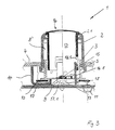
- FIG. 3 is a vertical sectional view of a rotary controller of this invention in an embodiment having a key function.
- FIG. 1 shows a simplified representation of a rotary switch 1 , represented here as a rotary controller, including a hollow rotary knob 2 that cooperates with a rotary-knob lower part 3 and is mounted in a panel 4 , such as a front panel of a dashboard of a motor vehicle.
- a rotary switch 1 represented here as a rotary controller, including a hollow rotary knob 2 that cooperates with a rotary-knob lower part 3 and is mounted in a panel 4 , such as a front panel of a dashboard of a motor vehicle.
- the rotary-knob lower part 3 (or rotary knob 2 , which is not shown in detail here) has spring elements 5 distributed on its outer perimeter, extending into recesses in the rotary-knob lower part 3 or rotary knob 2 . Between the rotary knob 2 and the rotary-knob lower part 3 there is a clearance, or space, 8 .
- the rotary controller 1 has a bore 9 , for example in the rotary-knob lower part 3 , for a light coupling (not shown in detail here).
- a wiper plate 10 is mounted on the rotary-knob lower part 3 from which a signal is picked up in a known manner by a contact, or wiper, 11 of a base plate 7 .
- FIG. 2 shows basically the rotary controller 1 from FIG. 1, but with frangible ribs 6 . These ribs 6 have intended breaking point(s) 6 . 1 in predetermined areas.
- frangible ribs 6 have intended breaking point(s) 6 . 1 in predetermined areas.
- the same reference numbers are used in FIG. 2 as in FIG. 1, so that it is not necessary to repeat the reference numbers again in further describing FIG. 2 .
- a higher force acts on the rotary controller 1 from the rear toward a direction of travel, for example due to an impact of a driver's body, this force being greater than a force of the spring elements 5 or the stability of ribs 6 .
- the rotary knob 2 is no longer supported due to the yielding, or breaking, away of the spring elements 5 or the ribs 6 at the so-called yield or breaking points, and it moves through the panel 4 in the direction of the rotary-knob lower part 3 and the base plate 7 due to the acting force.
- the collapsed, or crushed, parts and rotary-knob lower part 3 are then pressed into the clearance, or space, 8 in the rotary knob 2 .
- a key 13 is integrated into a rotary knob 2 of the type in FIG. 1, the key being held mechanically by a holder 14 .
- the rotary-knob lower part 3 is then supported on the holder 14 .
- the key 13 has vertical guide grooves 13 . 1 in which the holder 14 engages with its retaining fingers 14 . 1 .
- three guide grooves 13 . 1 are provided.
- the key path here is limited by a depression 2 . 1 in the rotary knob top part 2 .
- the retaining fingers 14 . 1 preferably engage with the guide grooves 13 . 1 from the inside.
- the key 13 has a light guide 15 , one end of which preferably extends into the key 13 and projects into a head area of the key 13 to illuminate a key symbol 16 .
- This light guide 15 engages with a contact dome 17 that has a central passage 17 . 1 for a light of a light element 18 of a circuit board 19 , for example an LED. Closing the contacts in the contact dome 17 with contacts on the circuit board 19 takes place via the contact dome 17 when the key 13 is depressed.
- the rotary-knob lower part 3 On impact of a vehicle, which is not shown in detail here, the rotary-knob lower part 3 is pushed into the clearance space 8 ′ between the key 13 and the rotary knob 2 upon breakage, or yielding, of the upper part of the spring element 5 or the intended breaking points 6 . 1 of the ribs 6 of the rotary controller 1 .
- the retaining fingers 14 . 1 leave the guide groove 13 . 1 in this process and bend into the hollow part of the key 13 .
- the retaining fingers 14 . 1 were acting on the key 13 from the outside, they would also be displaced into the clearance 8 ′n, but a larger clearance 8 ′ would have to be provided between the key 13 and the rotary knob 2 , so that, in addition to the rotary-knob lower part 3 , the retaining fingers 14 . 1 would also have room in this clearance space 8 ′.
- this invention is not limited just to motor vehicles and commercial vehicles.
- the rotary controller 1 disclosed here may also be used in aircraft and in rail vehicles that must meet similar requirements, that is, the requirement that the rotary knob top part 2 should not continue to project out of the panel 4 when high forces are acting on it from the outside, so that the risk of injury can be reduced.
Landscapes
- Physics & Mathematics (AREA)
- General Physics & Mathematics (AREA)
- Engineering & Computer Science (AREA)
- Automation & Control Theory (AREA)
- Rotary Switch, Piano Key Switch, And Lever Switch (AREA)
- Switch Cases, Indication, And Locking (AREA)
- Switches With Compound Operations (AREA)
Abstract
A rotary switch or controller is structured to have a so-called impact criteria or characteristic by having members with predetermined yield, or breaking, points (5, 6) which are integrated into the rotary switch (1) so that when a high force acts on the rotary switch (1), a top part (2) of a rotary switch or rotary controller (1) is allowed to be collapsed into a front panel (4) of a passenger vehicle or commercial vehicle on which the rotary switch is used. These yield elements (5, 6) may be structured as ribs (6) that have intended breaking points (6.1) therebetween, or may be structured as spring elements (5).
Description
This application claims a priority based on German application 199 64 133.1, filed Nov. 22, 1999, and the contents of that application are incorporated herein by reference.
The present invention relates to a rotary switch having a rotary knob, or button, with a rotary-knob lower part.
Rotary switches are often used in dashboard panels and other places in automotive engineering. Such rotary switches or rotary resistors are known from German Patent 197 12 294 C1, German Patent 196 36 643 C1 as well as German Patent Application 198 34 374 A1. In a particular structure, rotary switches are also structured as compact rotary controllers.
It is a disadvantage that known rotary switches, or rotary controllers, do not meet head-impact criteria, in that they often project too far out of the front panel of the dashboard of the vehicle in the event of a crash.
An object of this invention is to provide a rotary switch that conforms to head-impact criteria, or requirements.
According to principles of this invention, a rotary switch has predetermined yield, or breaking, points, or areas, which are provided on a rotary knob or a rotary-knob lower part so that when a high force acts on the rotary switch these members are collapsed at these yield points and the rotary knob is shifted toward a rotary-knob lower part.
This invention is based on the idea of integrating a displaceable, or collapsible, material into a rotary switch, for example by having yield points which permit the rotary switch to sink into a front panel of a passenger vehicle or commercial vehicle under increased pressure of an impact. Fracture, or breaking, point members may be structured as ribs that yield and have the predetermined yield points or they may be structured as spring elements. For deformation of the rotary switch into itself, hollow spaces are created into which the rotary knob, or a rotary-knob lower part, can be depressed, for which purpose these hollow spaces are built into the respective mating piece. These spaces are structured so that the ribs and spring elements have the opportunity to sink further in the event of a impact.
Further benefits, characteristics and details of the invention are explained in more detail below using an embodiment shown in the drawings. The described and drawn features, can be used individually or in preferred combinations in other embodiments of the invention. The foregoing and other objects, features and advantages of the invention will be apparent from the following more particular description of the preferred embodiment of the invention, as illustrated in the accompanying drawings in which reference characters refer to the same parts throughout the different views. The drawings are not necessarily to scale, emphasis instead being placed upon illustrating principles of the invention in a clear manner.
FIG. 1 is a vertical sectional view of a rotary switch of this invention in a particular structure as a rotary controller and having spring elements;
FIG. 2 is a view similar to FIG. 1 of a rotary switch of this invention having ribs; and
FIG. 3 is a vertical sectional view of a rotary controller of this invention in an embodiment having a key function.
FIG. 1 shows a simplified representation of a rotary switch 1, represented here as a rotary controller, including a hollow rotary knob 2 that cooperates with a rotary-knob lower part 3 and is mounted in a panel 4, such as a front panel of a dashboard of a motor vehicle.
For meeting button impact criteria, or requirements, the rotary-knob lower part 3 (or rotary knob 2, which is not shown in detail here) has spring elements 5 distributed on its outer perimeter, extending into recesses in the rotary-knob lower part 3 or rotary knob 2. Between the rotary knob 2 and the rotary-knob lower part 3 there is a clearance, or space, 8. In addition, the rotary controller 1 has a bore 9, for example in the rotary-knob lower part 3, for a light coupling (not shown in detail here). A wiper plate 10 is mounted on the rotary-knob lower part 3 from which a signal is picked up in a known manner by a contact, or wiper, 11 of a base plate 7.
FIG. 2 shows basically the rotary controller 1 from FIG. 1, but with frangible ribs 6. These ribs 6 have intended breaking point(s) 6.1 in predetermined areas. For the sake of simplicity, the same reference numbers are used in FIG. 2 as in FIG. 1, so that it is not necessary to repeat the reference numbers again in further describing FIG. 2.
A function of the spring elements 5 and the ribs 6 is described below.
In a case of an impact of a vehicle (not shown here) a higher force acts on the rotary controller 1 from the rear toward a direction of travel, for example due to an impact of a driver's body, this force being greater than a force of the spring elements 5 or the stability of ribs 6. This results in a yielding or collapsing of them, either at upper parts of the spring elements 5 or at the predetermined breaking points 6.1 of the ribs 6. The rotary knob 2 is no longer supported due to the yielding, or breaking, away of the spring elements 5 or the ribs 6 at the so-called yield or breaking points, and it moves through the panel 4 in the direction of the rotary-knob lower part 3 and the base plate 7 due to the acting force. The collapsed, or crushed, parts and rotary-knob lower part 3 are then pressed into the clearance, or space, 8 in the rotary knob 2.
If the spring elements 5 or the ribs 6 were on the rotary knob 2, the same movement would take place, and the rotary knob 2 would still move in the direction of the rotary-knob lower part 3, but in this case the clearance space would have to be present in the mating piece, that is, in the rotary-knob lower part 3.
In another embodiment of FIG. 3, a key 13 is integrated into a rotary knob 2 of the type in FIG. 1, the key being held mechanically by a holder 14. The rotary-knob lower part 3 is then supported on the holder 14. The key 13 has vertical guide grooves 13.1 in which the holder 14 engages with its retaining fingers 14.1. For uniform keying, preferably three guide grooves 13.1 are provided. The key path here is limited by a depression 2.1 in the rotary knob top part 2. If the key 13 is a hollow key element as in this embodiment, the retaining fingers 14.1 preferably engage with the guide grooves 13.1 from the inside.
The key 13 has a light guide 15, one end of which preferably extends into the key 13 and projects into a head area of the key 13 to illuminate a key symbol 16. This light guide 15 engages with a contact dome 17 that has a central passage 17.1 for a light of a light element 18 of a circuit board 19, for example an LED. Closing the contacts in the contact dome 17 with contacts on the circuit board 19 takes place via the contact dome 17 when the key 13 is depressed.
On impact of a vehicle, which is not shown in detail here, the rotary-knob lower part 3 is pushed into the clearance space 8′ between the key 13 and the rotary knob 2 upon breakage, or yielding, of the upper part of the spring element 5 or the intended breaking points 6.1 of the ribs 6 of the rotary controller 1. The retaining fingers 14.1 leave the guide groove 13.1 in this process and bend into the hollow part of the key 13.
If the retaining fingers 14.1 were acting on the key 13 from the outside, they would also be displaced into the clearance 8′n, but a larger clearance 8′ would have to be provided between the key 13 and the rotary knob 2, so that, in addition to the rotary-knob lower part 3, the retaining fingers 14.1 would also have room in this clearance space 8′.
However, this invention is not limited just to motor vehicles and commercial vehicles. The rotary controller 1 disclosed here may also be used in aircraft and in rail vehicles that must meet similar requirements, that is, the requirement that the rotary knob top part 2 should not continue to project out of the panel 4 when high forces are acting on it from the outside, so that the risk of injury can be reduced.
Claims (15)
1. A rotary switch having a rotary knob and a rotary-knob lower part formed as a separate piece from said rotary knob but cooperating therewith to transmit switch adjustments, wherein the rotary switch has members with predetermined yield points located on an outer perimeter of one of the rotary knob and the rotary-knob lower part for supporting the rotary knob, so that when a high force acts on the rotary switch, the members with predetermined yield points yield at these yield points and the rotary knob is collapsed toward the rotary-knob lower part, wherein the members with the predetermined yield points are formed as pieces separate from said rotary knob and the rotary-knob lower part; and
wherein there is a key element that is additionally integrated into the rotary knob top part, and a holder that mechanically holds the key element, with the rotary-knob lower part being positioned on the holder, wherein said holder has retaining fingers engaging in guide grooves in the periphery of the key element.
2. The rotary switch of claim 1 , wherein the members with predetermined yield points are crushed when they collapse.
3. The rotary switch of claim 1 , wherein the one of the rotary knob and the rotary-knob lower part on whose outer perimeter the members with the predetermined yield points are located, are driven into a hollow cavity of the other of the rotary knob and the rotary-knob lower part, along with the members with the predetermined yield points when the rotary knob is collapsed toward the rotary-knob lower part.
4. The rotary switch of claim 1 , wherein the members with predetermined yield points are formed by spring elements.
5. The rotary switch of claim 1 , wherein the members with predetermined yield points are formed by ribs with intended breaking points.
6. The rotary switch of claim 1 , wherein the members with predetermined yield points are driven into a hollow cavity between the rotary knob and the rotary-knob lower part while the retaining fingers leave the guide grooves.
7. The rotary switch of claim 6 , wherein the key is placed over a light guide, which illuminates a facing area of the key to illuminate a key symbol thereon, and wherein the key engages a contact dome having a central opening.
8. A rotary switch as in claim 1 , wherein the rotary-knob lower part has an electrical-contact wiper blade mounted thereon for further transmitting said switch adjustments.
9. A rotary switch having a rotary knob and a rotary-knob lower part formed as a separate piece from said rotary knob but cooperating therewith to transmit switch adjustments,
wherein the rotary switch has members with predetermined yield points located on an outer perimeter of one of the rotary knob and the rotary-knob lower part for supporting the rotary knob, so that when a high force acts on the rotary switch, the members with predetermined yield points yield at these yield points and the rotary knob is collapsed toward the rotary-knob lower part,
wherein the members with predetermined yield points are formed of pieces separate from said rotary knob and the rotary-knob lower part and they are located in recesses of the one of the rotary knob and the rotary-knob lower part before the rotary knob is collapsed toward the rotary-knob lower part.
10. The rotary switch of claim 1 , wherein there is a key element that is additionally integrated into the rotary knob top part, and a holder that mechanically holds the key element, with the rotary-knob lower part being positioned on the holder, wherein said holder has retaining fingers engaging in guide grooves in the periphery of the key element.
11. The rotary switch of claim 10 , wherein the members with predetermined yield points are driven into a hollow cavity between the rotary knob and the rotary-knob lower part while the retaining fingers leave the guide grooves.
12. The rotary switch of claim 11 , wherein the key is placed over a light guide, which illuminates a facing area of the key to illuminate a key symbol thereon, and wherein the key engages a contact dome having a central opening.
13. A rotary switch having a rotary knob and a rotary-knob lower part formed as a separate piece from said rotary knob but cooperating therewith to transmit switch adjustments,
wherein the rotary switch has members with predetermined yield points located on an outer perimeter of one of the rotary knob and the rotary-knob lower part for supporting the rotary knob, so that when a high force acts on the rotary switch, the members with predetermined yield points yield at these yield points and the rotary knob is collapsed toward the rotary-knob lower part,
wherein there is a key element that is additionally integrated into the rotary knob top part, and a holder that mechanically holds the key element, with the rotary-knob lower part being positioned on the holder, wherein said holder has retaining fingers engaging in guide grooves in the periphery of the key element.
14. The rotary switch of claim 13 , wherein the members with predetermined yield points are driven into a hollow cavity between the rotary knob and the rotary-knob lower part while the retaining fingers leave the guide grooves.
15. The rotary switch of claim 14 , wherein the key is placed over a light guide, which illuminates a facing area of the key to illuminate a key symbol thereon, and wherein the key engages a contact dome central opening.
Applications Claiming Priority (2)
| Application Number | Priority Date | Filing Date | Title |
|---|---|---|---|
| DE19964133 | 1999-11-22 | ||
| DE19964133A DE19964133A1 (en) | 1999-11-22 | 1999-11-22 | Rotary switch |
Publications (1)
| Publication Number | Publication Date |
|---|---|
| US6512189B1 true US6512189B1 (en) | 2003-01-28 |
Family
ID=7935229
Family Applications (1)
| Application Number | Title | Priority Date | Filing Date |
|---|---|---|---|
| US09/715,173 Expired - Fee Related US6512189B1 (en) | 1999-11-22 | 2000-11-20 | Rotary switch |
Country Status (4)
| Country | Link |
|---|---|
| US (1) | US6512189B1 (en) |
| EP (1) | EP1102289B1 (en) |
| JP (1) | JP2001189116A (en) |
| DE (2) | DE19964133A1 (en) |
Cited By (18)
| Publication number | Priority date | Publication date | Assignee | Title |
|---|---|---|---|---|
| US20020145337A1 (en) * | 2001-04-04 | 2002-10-10 | Halla Climate Control Corporation | Mode switch assembly of automobile having impact/load absorbing apparatus |
| US6670567B1 (en) * | 2000-02-24 | 2003-12-30 | Zexel Valeo Climate Control Corporation | Rotary switch mechanism for operation panel |
| US6674026B2 (en) * | 2002-05-10 | 2004-01-06 | Tektronix, Inc. | Rear mounted integrated rotary encoder including a pushbutton switch |
| US6686551B2 (en) * | 2001-09-21 | 2004-02-03 | Menber's Spa | Switch, in particular battery cutout switch for vehicles and the like |
| US20040105246A1 (en) * | 2002-11-28 | 2004-06-03 | Heiko Glienicke | Control element |
| EP1477876A1 (en) * | 2003-05-13 | 2004-11-17 | Matsuhita Electric Industrial Co., Ltd. | Electronic equipment |
| US20050023121A1 (en) * | 2003-07-29 | 2005-02-03 | Jin Seong-Ki | Switch assembly |
| US20060181434A1 (en) * | 2005-02-17 | 2006-08-17 | Takashi Ichihara | Electronic apparatus |
| US20060283285A1 (en) * | 2004-08-27 | 2006-12-21 | Hiroyuki Yabashi | Operation mechanism |
| US20070103884A1 (en) * | 2005-11-09 | 2007-05-10 | Popowich David J | Illuminated dial |
| US20080023313A1 (en) * | 2006-07-28 | 2008-01-31 | Sack James A | Control knob with safety feature |
| US20080023309A1 (en) * | 2006-07-31 | 2008-01-31 | Montalvo Juan J | Rotary knob with a display |
| US20080236329A1 (en) * | 2007-03-30 | 2008-10-02 | Motorola, Inc. | Rotary knob assembly |
| US20080263830A1 (en) * | 2007-04-26 | 2008-10-30 | Denso Corporation | Operating knob |
| US20090260963A1 (en) * | 2008-04-17 | 2009-10-22 | Hideaki Eto | Vehicle switch |
| CN101490775B (en) * | 2006-07-12 | 2011-07-06 | 住友电装株式会社 | vehicle switch |
| CN103363091A (en) * | 2013-07-12 | 2013-10-23 | 浙江吉利汽车研究院有限公司杭州分公司 | Knob type gear shifting device |
| CN112413864A (en) * | 2020-11-25 | 2021-02-26 | 重庆瑞阳吉星科技有限公司 | Double-temperature-zone air conditioner controller |
Families Citing this family (16)
| Publication number | Priority date | Publication date | Assignee | Title |
|---|---|---|---|---|
| DE10135734A1 (en) * | 2001-07-21 | 2003-02-06 | Bosch Gmbh Robert | operating element |
| DE20120667U1 (en) * | 2001-12-20 | 2002-12-12 | Siemens AG, 80333 München | Deformable push button |
| DE10236066B4 (en) * | 2002-08-07 | 2009-01-15 | Preh Gmbh | Operating element with a mechanical detent |
| DE10257258B3 (en) | 2002-12-07 | 2004-09-30 | Preh Gmbh | operating element |
| DE10261831A1 (en) * | 2002-12-20 | 2004-07-01 | Trw Automotive Electronics & Components Gmbh & Co. Kg | Crash responsive actuator element is displaced axially when crash force exceeds a set threshold value |
| DE10261284B4 (en) * | 2002-12-27 | 2017-12-07 | Volkswagen Ag | Rotatable control with display unit |
| DE10314315B4 (en) * | 2003-03-29 | 2006-03-30 | Preh Gmbh | operating element |
| DE10357138B3 (en) * | 2003-12-06 | 2005-06-23 | Behr Gmbh & Co. Kg | Operating and / or display device for the interior of a vehicle, in particular vehicle control unit |
| DE102007042765A1 (en) | 2007-09-07 | 2009-03-12 | Preh Gmbh | Push button/rotary switch/rotating actuator for commercial motor vehicle, has lining or system panel of passenger cabin accommodated in actuator, where actuator is movable from operating position to sinking position by applying force |
| DE102007046546A1 (en) * | 2007-09-27 | 2009-04-09 | Preh Gmbh | Multiple switch/rotary actuator for use in interior of vehicle, has inner control button moveable from operating position into depressed position or vice versa, where inner button is circularly enclosed by outer control button |
| DE102008046652B4 (en) * | 2007-10-29 | 2021-06-02 | Volkswagen Ag | Foot pedal on motor vehicles |
| JP5549406B2 (en) * | 2010-06-17 | 2014-07-16 | パナソニック株式会社 | Rotation switch |
| JP5697469B2 (en) | 2011-01-31 | 2015-04-08 | トヨタ自動車株式会社 | Operating device |
| DE102011089765A1 (en) | 2011-12-23 | 2013-06-27 | Behr-Hella Thermocontrol Gmbh | Operating and/or display device e.g. vehicle component operating and/or display unit for interior of vehicle, has guide sleeve and retaining ring that are automatically assembled by two-component injection molding process finished unit |
| CN106114437B (en) * | 2016-06-24 | 2018-08-28 | 惠州市德赛西威汽车电子股份有限公司 | A kind of collapsible supporting mechanism of automotive interior protrusion |
| CN108081955A (en) * | 2016-11-23 | 2018-05-29 | 宝沃汽车(中国)有限公司 | Vehicle and its knob assembly |
Citations (4)
| Publication number | Priority date | Publication date | Assignee | Title |
|---|---|---|---|---|
| US3066550A (en) * | 1960-06-20 | 1962-12-04 | Whirlpool Co | Home appliance control element |
| DE2941626A1 (en) | 1979-10-13 | 1981-04-23 | Fa. Leopold Kostal, 5880 Lüdenscheid | Collapsible knob for vehicle instrument panels - has partitioned inverted pyramid sides which fold together into knob top |
| DE19712294A1 (en) | 1997-03-24 | 1998-10-01 | Preh Elektro Feinmechanik | Rotational resistance |
| DE19834374A1 (en) | 1998-07-30 | 2000-02-03 | Preh Elektro Feinmechanik | Knob of a control unit |
Family Cites Families (4)
| Publication number | Priority date | Publication date | Assignee | Title |
|---|---|---|---|---|
| US3182162A (en) * | 1962-01-22 | 1965-05-04 | Gen Motors Corp | Safety switch for automobile instrument panel |
| DE1965600U (en) * | 1967-03-11 | 1967-08-03 | Happich Gmbh Gebr | CONTROL KNOB, ESPECIALLY FOR SWITCHES, SLIDES, WINDOW HANDLES, OR WINDOW HANDLES TO BE MOUNTED IN MOTOR VEHICLES DGL. |
| US3645353A (en) * | 1970-04-23 | 1972-02-29 | Gen Motors Corp | Control element mounting arrangement |
| DE19636643C1 (en) * | 1996-09-10 | 1998-02-12 | Preh Elektro Feinmechanik | Knob top |
-
1999
- 1999-11-22 DE DE19964133A patent/DE19964133A1/en not_active Ceased
-
2000
- 2000-10-21 DE DE50012850T patent/DE50012850D1/en not_active Expired - Lifetime
- 2000-10-21 EP EP00122923A patent/EP1102289B1/en not_active Expired - Lifetime
- 2000-11-17 JP JP2000351206A patent/JP2001189116A/en not_active Withdrawn
- 2000-11-20 US US09/715,173 patent/US6512189B1/en not_active Expired - Fee Related
Patent Citations (4)
| Publication number | Priority date | Publication date | Assignee | Title |
|---|---|---|---|---|
| US3066550A (en) * | 1960-06-20 | 1962-12-04 | Whirlpool Co | Home appliance control element |
| DE2941626A1 (en) | 1979-10-13 | 1981-04-23 | Fa. Leopold Kostal, 5880 Lüdenscheid | Collapsible knob for vehicle instrument panels - has partitioned inverted pyramid sides which fold together into knob top |
| DE19712294A1 (en) | 1997-03-24 | 1998-10-01 | Preh Elektro Feinmechanik | Rotational resistance |
| DE19834374A1 (en) | 1998-07-30 | 2000-02-03 | Preh Elektro Feinmechanik | Knob of a control unit |
Cited By (31)
| Publication number | Priority date | Publication date | Assignee | Title |
|---|---|---|---|---|
| US6670567B1 (en) * | 2000-02-24 | 2003-12-30 | Zexel Valeo Climate Control Corporation | Rotary switch mechanism for operation panel |
| US6696769B2 (en) * | 2001-04-04 | 2004-02-24 | Halla Climate Control Corporation | Mode switch assembly of automobile having impact/load absorbing apparatus |
| US20020145337A1 (en) * | 2001-04-04 | 2002-10-10 | Halla Climate Control Corporation | Mode switch assembly of automobile having impact/load absorbing apparatus |
| US6686551B2 (en) * | 2001-09-21 | 2004-02-03 | Menber's Spa | Switch, in particular battery cutout switch for vehicles and the like |
| US6674026B2 (en) * | 2002-05-10 | 2004-01-06 | Tektronix, Inc. | Rear mounted integrated rotary encoder including a pushbutton switch |
| US20040105246A1 (en) * | 2002-11-28 | 2004-06-03 | Heiko Glienicke | Control element |
| US7251861B2 (en) * | 2003-05-13 | 2007-08-07 | Matsushita Electric Industrial Co., Ltd. | Electronic equipment |
| EP1477876A1 (en) * | 2003-05-13 | 2004-11-17 | Matsuhita Electric Industrial Co., Ltd. | Electronic equipment |
| US20040226142A1 (en) * | 2003-05-13 | 2004-11-18 | Matsushita Electric Industrial Co., Ltd. | Electronic equiptment |
| US7586054B2 (en) * | 2003-07-29 | 2009-09-08 | Samsung Electronics Co., Ltd. | Switch assembly |
| US20050023121A1 (en) * | 2003-07-29 | 2005-02-03 | Jin Seong-Ki | Switch assembly |
| CN100454457C (en) * | 2004-08-27 | 2009-01-21 | 三菱电机株式会社 | operating mechanism |
| US20060283285A1 (en) * | 2004-08-27 | 2006-12-21 | Hiroyuki Yabashi | Operation mechanism |
| US20060181434A1 (en) * | 2005-02-17 | 2006-08-17 | Takashi Ichihara | Electronic apparatus |
| US7688969B2 (en) * | 2005-02-17 | 2010-03-30 | Panasonic Corporation | Operation dial with rotary encoder |
| US20070103884A1 (en) * | 2005-11-09 | 2007-05-10 | Popowich David J | Illuminated dial |
| US7222979B1 (en) | 2005-11-09 | 2007-05-29 | Cfm Corporation | Illuminated dial |
| CN101490775B (en) * | 2006-07-12 | 2011-07-06 | 住友电装株式会社 | vehicle switch |
| US7479607B2 (en) * | 2006-07-28 | 2009-01-20 | Bose Corporation | Control knob with safety feature |
| CN101490635B (en) * | 2006-07-28 | 2012-05-23 | 伯斯有限公司 | Control knob with safety feature |
| US20080023313A1 (en) * | 2006-07-28 | 2008-01-31 | Sack James A | Control knob with safety feature |
| US20080023309A1 (en) * | 2006-07-31 | 2008-01-31 | Montalvo Juan J | Rotary knob with a display |
| US7462795B2 (en) * | 2006-07-31 | 2008-12-09 | Delphi Technologies, Inc. | Rotary knob with a display |
| US20080236329A1 (en) * | 2007-03-30 | 2008-10-02 | Motorola, Inc. | Rotary knob assembly |
| US8220361B2 (en) | 2007-03-30 | 2012-07-17 | Motorola Solutions, Inc. | Rotary knob assembly |
| US7908713B2 (en) * | 2007-04-26 | 2011-03-22 | Denso Corporation | Operating knob |
| US20080263830A1 (en) * | 2007-04-26 | 2008-10-30 | Denso Corporation | Operating knob |
| US20090260963A1 (en) * | 2008-04-17 | 2009-10-22 | Hideaki Eto | Vehicle switch |
| US8084699B2 (en) * | 2008-04-17 | 2011-12-27 | Panasonic Corporation | Vehicle switch |
| CN103363091A (en) * | 2013-07-12 | 2013-10-23 | 浙江吉利汽车研究院有限公司杭州分公司 | Knob type gear shifting device |
| CN112413864A (en) * | 2020-11-25 | 2021-02-26 | 重庆瑞阳吉星科技有限公司 | Double-temperature-zone air conditioner controller |
Also Published As
| Publication number | Publication date |
|---|---|
| JP2001189116A (en) | 2001-07-10 |
| DE19964133A1 (en) | 2001-06-13 |
| EP1102289B1 (en) | 2006-05-31 |
| DE50012850D1 (en) | 2006-07-06 |
| EP1102289A2 (en) | 2001-05-23 |
| EP1102289A3 (en) | 2003-05-02 |
Similar Documents
| Publication | Publication Date | Title |
|---|---|---|
| US6512189B1 (en) | Rotary switch | |
| EP2980671B1 (en) | Control knob device | |
| EP0159282A2 (en) | A control pod and switch assembly | |
| SE1550581A1 (en) | Vehicle comprising collision control systeSm, collision control system and method | |
| US7638719B2 (en) | Operating element | |
| GB2262591A (en) | Vehicle air bag cover with horn switch actuating portion. | |
| US7060920B2 (en) | Multi-stage click switch | |
| EP1139359B1 (en) | Switch device and method of assembling switch device | |
| CN100376432C (en) | Airbag system | |
| CN101287627A (en) | Air bag device and steering wheel | |
| US20010052694A1 (en) | Multifunctional steering wheel | |
| DE102019103752A1 (en) | Steering device, gas bag module for this steering device and method for triggering a horn signal in such a steering device | |
| US20160104589A1 (en) | Switch device for vehicular air conditioning system | |
| US6849816B2 (en) | Vehicle steering wheel | |
| EP0754597B1 (en) | Driver's side airbag cover incorporating function switches | |
| KR100980716B1 (en) | Mounting structure of the crash pad | |
| US6121558A (en) | Steering column switch | |
| WO2003062029A8 (en) | Pedal support structure comprising an anti-collision safety mechanism | |
| EP3312863B1 (en) | Switch device in particular for a use in a push pull window lifter mechanism | |
| CN113525495B (en) | Steering wheel | |
| KR100217617B1 (en) | Airbag cover of car with horn switch | |
| KR100252292B1 (en) | A steering column and shaft for shock absorbing | |
| JPS6076443A (en) | Switch built-in steering wheel | |
| KR100292106B1 (en) | Construction of air bag out cover assembly | |
| KR100836693B1 (en) | Button-driven starting device of a vehicle |
Legal Events
| Date | Code | Title | Description |
|---|---|---|---|
| AS | Assignment |
Owner name: PREH-WERKE GMBH & CO., KG, GERMANY Free format text: ASSIGNMENT OF ASSIGNORS INTEREST;ASSIGNORS:SCHUBERTH, STEFAN;ZEGULA, OLIVER;REEL/FRAME:011628/0508;SIGNING DATES FROM 20001205 TO 20001206 |
|
| FEPP | Fee payment procedure |
Free format text: PAYOR NUMBER ASSIGNED (ORIGINAL EVENT CODE: ASPN); ENTITY STATUS OF PATENT OWNER: LARGE ENTITY |
|
| FPAY | Fee payment |
Year of fee payment: 4 |
|
| REMI | Maintenance fee reminder mailed | ||
| LAPS | Lapse for failure to pay maintenance fees | ||
| STCH | Information on status: patent discontinuation |
Free format text: PATENT EXPIRED DUE TO NONPAYMENT OF MAINTENANCE FEES UNDER 37 CFR 1.362 |
|
| FP | Lapsed due to failure to pay maintenance fee |
Effective date: 20110128 |