US6509118B1 - Valve-regulated lead-acid cells and batteries and separators used in such cells and batteries - Google Patents
Valve-regulated lead-acid cells and batteries and separators used in such cells and batteries Download PDFInfo
- Publication number
- US6509118B1 US6509118B1 US09/423,026 US42302600A US6509118B1 US 6509118 B1 US6509118 B1 US 6509118B1 US 42302600 A US42302600 A US 42302600A US 6509118 B1 US6509118 B1 US 6509118B1
- Authority
- US
- United States
- Prior art keywords
- separator
- polymer
- lead
- cell
- modified
- Prior art date
- Legal status (The legal status is an assumption and is not a legal conclusion. Google has not performed a legal analysis and makes no representation as to the accuracy of the status listed.)
- Expired - Lifetime
Links
Images


Classifications
-
- H—ELECTRICITY
- H01—ELECTRIC ELEMENTS
- H01M—PROCESSES OR MEANS, e.g. BATTERIES, FOR THE DIRECT CONVERSION OF CHEMICAL ENERGY INTO ELECTRICAL ENERGY
- H01M50/00—Constructional details or processes of manufacture of the non-active parts of electrochemical cells other than fuel cells, e.g. hybrid cells
- H01M50/40—Separators; Membranes; Diaphragms; Spacing elements inside cells
- H01M50/409—Separators, membranes or diaphragms characterised by the material
- H01M50/44—Fibrous material
-
- H—ELECTRICITY
- H01—ELECTRIC ELEMENTS
- H01M—PROCESSES OR MEANS, e.g. BATTERIES, FOR THE DIRECT CONVERSION OF CHEMICAL ENERGY INTO ELECTRICAL ENERGY
- H01M50/00—Constructional details or processes of manufacture of the non-active parts of electrochemical cells other than fuel cells, e.g. hybrid cells
- H01M50/40—Separators; Membranes; Diaphragms; Spacing elements inside cells
- H01M50/403—Manufacturing processes of separators, membranes or diaphragms
-
- H—ELECTRICITY
- H01—ELECTRIC ELEMENTS
- H01M—PROCESSES OR MEANS, e.g. BATTERIES, FOR THE DIRECT CONVERSION OF CHEMICAL ENERGY INTO ELECTRICAL ENERGY
- H01M50/00—Constructional details or processes of manufacture of the non-active parts of electrochemical cells other than fuel cells, e.g. hybrid cells
- H01M50/40—Separators; Membranes; Diaphragms; Spacing elements inside cells
- H01M50/409—Separators, membranes or diaphragms characterised by the material
- H01M50/431—Inorganic material
- H01M50/434—Ceramics
- H01M50/437—Glass
-
- H—ELECTRICITY
- H01—ELECTRIC ELEMENTS
- H01M—PROCESSES OR MEANS, e.g. BATTERIES, FOR THE DIRECT CONVERSION OF CHEMICAL ENERGY INTO ELECTRICAL ENERGY
- H01M50/00—Constructional details or processes of manufacture of the non-active parts of electrochemical cells other than fuel cells, e.g. hybrid cells
- H01M50/40—Separators; Membranes; Diaphragms; Spacing elements inside cells
- H01M50/409—Separators, membranes or diaphragms characterised by the material
- H01M50/449—Separators, membranes or diaphragms characterised by the material having a layered structure
-
- H—ELECTRICITY
- H01—ELECTRIC ELEMENTS
- H01M—PROCESSES OR MEANS, e.g. BATTERIES, FOR THE DIRECT CONVERSION OF CHEMICAL ENERGY INTO ELECTRICAL ENERGY
- H01M10/00—Secondary cells; Manufacture thereof
- H01M10/34—Gastight accumulators
- H01M10/342—Gastight lead accumulators
-
- H—ELECTRICITY
- H01—ELECTRIC ELEMENTS
- H01M—PROCESSES OR MEANS, e.g. BATTERIES, FOR THE DIRECT CONVERSION OF CHEMICAL ENERGY INTO ELECTRICAL ENERGY
- H01M2300/00—Electrolytes
- H01M2300/0002—Aqueous electrolytes
- H01M2300/0005—Acid electrolytes
- H01M2300/0011—Sulfuric acid-based
-
- H—ELECTRICITY
- H01—ELECTRIC ELEMENTS
- H01M—PROCESSES OR MEANS, e.g. BATTERIES, FOR THE DIRECT CONVERSION OF CHEMICAL ENERGY INTO ELECTRICAL ENERGY
- H01M50/00—Constructional details or processes of manufacture of the non-active parts of electrochemical cells other than fuel cells, e.g. hybrid cells
- H01M50/40—Separators; Membranes; Diaphragms; Spacing elements inside cells
- H01M50/409—Separators, membranes or diaphragms characterised by the material
- H01M50/446—Composite material consisting of a mixture of organic and inorganic materials
-
- Y—GENERAL TAGGING OF NEW TECHNOLOGICAL DEVELOPMENTS; GENERAL TAGGING OF CROSS-SECTIONAL TECHNOLOGIES SPANNING OVER SEVERAL SECTIONS OF THE IPC; TECHNICAL SUBJECTS COVERED BY FORMER USPC CROSS-REFERENCE ART COLLECTIONS [XRACs] AND DIGESTS
- Y02—TECHNOLOGIES OR APPLICATIONS FOR MITIGATION OR ADAPTATION AGAINST CLIMATE CHANGE
- Y02E—REDUCTION OF GREENHOUSE GAS [GHG] EMISSIONS, RELATED TO ENERGY GENERATION, TRANSMISSION OR DISTRIBUTION
- Y02E60/00—Enabling technologies; Technologies with a potential or indirect contribution to GHG emissions mitigation
- Y02E60/10—Energy storage using batteries
Definitions
- the present invention relates to lead-acid cells and batteries, and, more particularly, to the separators used in valve-regulated lead-acid cells and batteries.
- Sealed lead-acid cells (often termed “VRLA” cells, viz., valve-regulated lead-acid) are widely used in commerce today.
- sealed lead-acid cells utilize highly absorbent separators, and the necessary electrolyte is absorbed in the separators and plates. Accordingly, such cells may be used in any attitude without electrolyte spillage as would occur with a flooded electrolyte lead-acid battery.
- Such cells are normally sealed from the atmosphere by a valve designed to regulate the internal pressure within the cell so as to provide what is termed an effective “oxygen recombination cycle” (hence, the use of the terms “sealed” and “valve-regulated”)
- Sealed lead-acid technology thus offers substantial benefits by eliminating maintenance (e.g., cell watering), expense (e.g., acid purchases), environmental concerns (e.g., expensive waste treatment systems and air-borne acid mist), and safety (e.g., acid burns).
- maintenance e.g., cell watering
- expense e.g., acid purchases
- environmental concerns e.g., expensive waste treatment systems and air-borne acid mist
- safety e.g., acid burns
- sealed lead-acid cells and batteries are widely used in commerce today for various applications that have widely differing requirements.
- lead-acid cells and batteries are used, for example, for load leveling, emergency lighting and commercial buildings, as standby power for cable television systems, and in uninterruptible power supplies.
- the uninterruptible power supply may be used to back up electronic equipment, such as, for example, telecommunication and computer systems, and even as a backup energy source for entire manufacturing plants.
- the sealed cells typically many electronically connected together
- the uninterruptible power supply also will accommodate short, or intermittent, losses in power, so that the function of the electronic equipment will not be impaired during a brief power outage.
- sealed lead-acid cells and batteries are used in what are termed motive power applications. Sealed lead-acid cells and batteries are thus used as the power source for electric vehicles, fork-lift trucks, and the like.
- VRLA cells and batteries are extremely complex and involves a variety of aspects.
- One important aspect is that VRLA cells must avoid conditions in service in which the temperature within the cell increases uncontrollably and irreversibly. It has thus been hypothesized that excessive water loss resulting in cell dry-out is the driving mechanism for thermal runaway in such cells. This water loss can be caused by hydrogen gassing at the negative electrode or oxygen gassing at the positive electrode through the electrolysis of water, or both.
- the oxygen recombination efficiency increases uncontrollably. Since this recombination reaction is highly exothermic, this tends to heat the cell. As the temperature rises, the cell tends to generate gas; and the recombination processes become even more efficient, thereby further increasing the cell temperature. In similar fashion, water loss increases the cell electrical resistance; and such increased cell resistance increases the cell temperature, thereby further increasing water loss. The cell is in thermal runaway.
- thermal runaway being an ongoing issue which must be considered in designing VRLA cells and batteries, the impact of a particular separator design on this issue is not well understood. Indeed, the issue of thermal runaway has been dealt with in other ways, as by the selection of the alloys used for the positive grids in such cells and batteries.
- a basic shortcoming of the separators typically used in VRLA cells and batteries is that, at higher battery temperatures (e.g., above about 50° C.), a decline in the mechanical and physico-chemical properties of the separators used has been observed. Such decline in properties leads to a decrease in efficiency of the closed oxygen cycle (viz., the oxygen recombination cycle) and to water loss, which shortens the active life of the cell or battery.
- VRLA cells and batteries have somewhat lower capacity, power and energy performance as compared to flooded electrolyte lead-acid cells and batteries.
- commercial VRLA cells and batteries typically provide some means of compressing the cell or battery elements (viz., the positive and negative plates with the separators interposed therebetween) so as to maintain contact and thereby increase the battery capacity.
- Such compression can lead to decline in the efficiency of the closed oxygen cycle, due to the reduced number and volume of the gas channels involved, which loss consequently can result in increased water loss.
- the separators utilized have been highly absorptive glass mat separators.
- Such separators are usually, but not necessarily, thicker than the separators used in flooded electrolyte lead-acid cells and batteries and have substantially higher absorptivity.
- Such separators are often termed as “absorptive glass mats.”
- Such absorptive glass mat separators are well known in this field, and several companies supply such separator materials.
- Another and related object of this invention is to provide VRLA cells and batteries capable of achieving enhanced cycle life and energy performance characteristics.
- Yet another object of the present invention is to provide facile methods for making such separators.
- the present invention is predicated on the discovery that VRLA cells and batteries having enhanced cycle life and electrical performance can be provided by utilizing absorptive glass mat separators modified by treatment with appropriate polymers.
- Suitable polymers comprise hydrophobic polymers such as polyolefins, polyvinylchlorides, polyacrylonitriles, and polyesters, amphiphilic copolymers, graft copolymers, and hydrophilic nitrogen-containing, water-soluble polymers.
- surface active agents can be included.
- modification of the absorptive glass mat separators can be achieved by treating such separators with polymeric emulsions or dispersions of the selected polymer. While other types of emulsions can be used, it is desirable from an environmental standpoint to utilize aqueous polymeric emulsions.
- modified absorptive glass mat separators impart enhanced mechanical properties and achieve improved electrical performance characteristics in VRLA cells and batteries. Providing such modified absorptive glass mat separators can thus be achieved in a facile fashion.
- the individual layer can be treated so as to provide characteristics tailored more specifically to the location of the separator layer in VRLA cells and batteries. More specifically, as will be discussed in greater detail herein, it is desirable, in a preferred aspect of the present invention, to utilized double layer separators in which the relative hydrophilicity of the layers comprising the separator are different so as to enhance the efficiency of the closed oxygen cycle.
- FIG. 1 is a schematic view of a process for making the modified absorptive glass mat separators
- FIG. 2 is a perspective view of an exemplary VRLA cell with the container and cover partially broken away so as to show the internal configuration of the cell.
- FIG. 1 illustrates schematically one method for making the modified absorptive glass mat separators in conjunction with the present invention.
- the model conveyor-line scheme shown generally at 10 comprises first unrolling a roll 12 of the absorptive glass mat separator material.
- the term “absorptive glass mat” comprises any such material useful for making separators for VRLA cells and batteries. A variety of such materials are known and are commercially available. Indeed, this terminology includes absorptive glass mat separators which incorporate a minor amount of polymer fibers, as is also known. Indeed, while not preferred, it should be appreciated that the modified separators of the present invention could include absorptive mats made predominantly from polymer fibers, and, indeed, made essentially with only polymer fibers, if such configurations are considered desirable for specific applications.
- the absorptive glass mat is treated by applying a polymeric emulsion or dispersion of the selected polymer or polymers so as to coat the glass mat with the selected emulsion.
- a polymeric emulsion or dispersion of the selected polymer or polymers so as to coat the glass mat with the selected emulsion.
- an emulsion bath 14 containing the polymer emulsion 16 is applied via rolls 18 and 20 to the absorptive glass mat 22 .
- emulsion as used herein is considered to also refer to what would literally be termed “dispersions.”
- the polymer or polymers selected be capable of being applied by coating techniques, as can both polymer emulsions and dispersions. From an environmental standpoint, aqueous emulsions and dispersions are preferred. However, if desired, organic media can be employed.
- time is provided to allow absorption of the polymer emulsion into the absorptive glass mat 22 .
- rolls 24 , 26 , 28 and 30 are spaced to allow travel of the coated, and thus-modified, absorptive glass mat for a time period sufficient to allow the emulsion to be adequately absorbed into the glass mat.
- the time involved will be somewhat dependent upon the rate of travel and the length of travel of the coated glass mat. Typical speeds allow absorption within no more than about several minutes, e.g., 5 minutes or so.
- the thus-treated glass mat is subjected to a sintering step in which the emulsion is dried to fix the polymeric coating on the glass mat fibers.
- this step can be achieved by utilizing a conventional tunnel dryer.
- the absorptive glass mat 22 passes around roll 32 and enters tunnel dryer 34 .
- Suitable drying and sintering will be dependent, of course, upon the length and time of travel in the tunnel dryer or other dryer utilized. It should be appropriate to achieve drying by a residence time of no more than several minutes, 5 to 10 minutes or so being satisfactory.
- the thus-sintered and dried absorptive glass mat can then be passed through rolls 36 and wound as a roll 38 .
- FIG. 1 is merely illustrative of one method by which the absorptive glass mat separators may be modified in accordance with the present invention.
- the absorptive mat could travel through an emulsion of the selected polymer or polymers.
- the absorptive glass mat could be coated on both surfaces.
- Many other techniques are known and can be used.
- the particular method used for applying the selected polymer or polymers to the absorptive glass mat can be varied widely.
- the polymers selected can be applied by means other than emulsions or dispersions, although the use of polymeric emulsions provide a ready and facile method for achieving the separators of the present invention.
- the polymeric emulsion in the general method disclosed results in coating at least part of the glass fiber surface with a polymeric coating. Further, it is believed that the polymeric coating concentrates mainly at or adjacent to the sites of contact between the glass fibers. Thus, it is believed that the absorptive glass mat (characterized by adjacent, but unconnected, fibers) is thereby interconnected into what can be considered as a continuous network of fibers.
- suitable polymers are selected based upon the desired properties.
- suitable polymers should have satisfactory chemical resistance to the sulfuric acid electrolyte employed as well as being thermally stable at relatively high temperatures, e.g., 50° C. and higher.
- suitable polymers should be mechanically stable when bonded to the absorptive glass fiber mat.
- particular polymers ranging from those having hydrophobic characteristics to hydrophilic polymers and polymers having both hydrophilic and hydrophobic properties can be utilized.
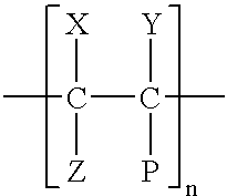
- hydrophobic polymers it is preferred to utilize polyolefins and substituted polyolefins having the general formula:
- n is an integer which is at least 50 and is less than 50,000.
- the substituents X, Y, Z, and P can be the same or different and may be fluorine, chlorine, hydrogen, an alkyl, aryl or alkyl-aryl radical. Suitable alkyls and aryl radicals can comprise any of the substituents used to modify polyolefins. Illustrative examples include: methyl, ethyl, propyl, benzyl, methylbenzyl, o-dimethylbenzyl, m-dimethylbenzyl, and p-dimethylbenzyl.
- a particularly preferred hydrophobic polymer comprises a polytetrafluoroethylene aqueous emulsion.
- a preferred polytetrafluoroethylene emulsion or dispersion is available from Hoescht AG under the trade name Teflon 5032.
- suitable hydrophobic polymers comprise various polyesters, polyvinylchlorides and polyacrylonitriles, many of which are known and are commercially available.
- Preferred polyesters include various polyalkylene terephthalates.
- copolymers include various amphiphilic block copolymers.
- Such copolymers include styrene and vinylpyrrolidone, styrene-ethylene oxide copolymers, multi-block copolymers of alkylene oxides or of alkylene and styrene oxides having the general formula:
- A is a hydrophobic block corresponding to the above formula for hydrophobic polymers or poly(alkyleneoxides) (except polyethylene oxide)
- B is a hydrophilic block comprising polyvinylpyrrolidone, polyacrylic acid, polyethylene oxide, polymaleic acid, or polystyrenesulfonic acid.
- a particularly preferred species is poly(N-vinylpyrrolidone-CO-styrene) (available as a 38% emulsion in water, Sigma-Aldrich Chemie GmbH).
- graft copolymers having hydrophilic-hydrophobic compositions include:
- a and A′ are hydrophobic blocks as polydimethylsiloxane, polyvinylchloride, polystyrene, polypropylene, polyethylene, and the like, and B and B′ are hydrophilic blocks as poly(ethylene oxide), poly(acrylic acid), poly(N-vinylpirrolidone), and the like.
- useful polymers include nitrogen-containing, water-soluble polymers specifically poly(vinylpyrrolidone) polymers according to the following general formula:
- various surface active agents may be included in the emulsion used to enhance the wettability of the polymer onto the glass fibers and to improve the hydrophilicity of the glass fibers.
- Any of a variety of surface active agents are known and may be utilized.
- Illustrative examples include ethoxynonylphenol, alkylethersulfate or symmetric or asymmetric multi-block copolymers of alkylene oxides or multi-block copolymers of alkylene oxides and styrene oxide.
- the amount of the polymer added to modify the absorptive glass mat separators can vary widely. In general, the amount utilized should be that sufficient to achieve the desired modification in properties. As an illustrative range, the amount of the polymer emulsion, or the polymer composition containing surfactants, can be from about 5 to about 50 grams per square meter of the absorptive glass mat.
- a 60wt. % aqueous emulsion of polytetrafluoroethylene is utilized, the emulsion being diluted with water to provide a concentration of about 3.5 to 14 grams of polytetrafluoroethylene per one liter of emulsion.
- the emulsion is applied to the absorptive glass mat from one or both surfaces of the mat so as to provide a polytetrafluoroethylene level of between 5.5 to 22 milligrams per 1 gram of the treated glass fiber mat.
- the thus-impregnated absorptive glass mat is placed in a thermal chamber to air dry by evaporation of the contained water.
- the mat is then passed through a curing chamber heated to a temperature of 320 to 380° C. for a period of about 3 to 8 minutes.
- the resulting modified absorptive glass mat separators should be positioned in the cell with the treated surface preferably, but not necessarily, facing the negative plates.
- a preferred surfactant comprises nonylphenol ethoxylated with 15 molecules of ethylene oxide, per the structure below:
- the surfactant is included in an amount of from about 1 to 2 grams per liter of the polytetrafluoroethylene emulsion.
- the obtained emulsion should then be stirred until fully homogenized. When used, the subsequent heating should be to a temperature of about 350° C.
- a further useful and preferred surfactant comprises a symmetric block copolymer of ethylene and propylene oxides having the following chemical structure:
- This copolymer may be added in an amount of about 1 gram per liter of the polytetrafluoroethylene emulsion.
- a further preferred surfactant for a polytetrafluoroethylene emulsion is polyvinylpyrrolidone.
- a particularly preferred species is a polyvinylpyrrolidone having an average molecular weight near 360,000 (available from Sigma-Aldrich Chemie GmbH). This surfactant may be added in an amount of about 0.25 to 2.5 grams per one liter of the polytetrafluoroethylene emulsion.
- the heating temperature utilized is 340° C.
- Yet another preferred surfactant comprises a poly(dimethylsiloxane) graft polyacrylate (available as a 10% aqueous solution). Such surfactant may be added in an amount of about 1 gram per 1 liter of the 60% polytetrafluoroethylene emulsion.
- a still further useful surfactant comprises an asymmetric block copolymer of ethylene and propylene oxides having the following formula:
- This surfactant may be added in an amount of 3 grams per 1 liter of the 60% polytetrafluoroethylene emulsion.
- the absorptive glass mats can be treated with an aqueous dispersion of polyvinylchloride.
- a preferred and suitable surfactant added is a symmetric 5-block copolymer of ethylene oxide and propylene oxide as set forth above, having an average molecular weight of about 3000 and wherein the terminal blocks of the copolymer are polyethylene oxide.
- An illustrative dispersion can comprise, for example, 1.25 parts of a 60% polyvinylchloride dispersion containing 5 grams of the surface active agent per 1 liter of the dispersion, the dispersion being diluted with 1,000 parts of water. The thus-obtained, diluted dispersion can be applied to the glass mat on either one or both surfaces. Heating in a curing chamber can suitably be carried out at a temperature of from about 140° C. to about 180° C.
- an aqueous emulsion or dispersion of polyethyleneterephthalate may be used.
- a preferred surfactant comprises alkylethersulfate.
- the procedures and the amounts utilized for polyvinylchloride can be the same for polyethyleneterephthalate. However, the temperature of heating should be about 240° C.
- the absorptive glass mats can be modified through treatment with a 60% aqueous emulsion of polyacrylonitrile.
- a suitable surfactant comprises the asymmetric block copolymer of ethylene and propylene oxides discussed in conjunction with polytetrafluoroethylene emulsions.
- the temperature of heating should be in the range of about 180° to 200° C.
- a still further preferred embodiment comprises an absorptive glass mat separator modified through treatment with a 38% aqueous emulsion of poly(N-vinylpyrrolidone-co-styrene).
- This emulsion may be diluted with water to provide a concentration of from about 0.05 to about 1 gram per 1 liter of emulsion.
- the emulsion may be applied to one or both surfaces of the glass mat so that the content of the dried polymer in the glass mat ranges from about 0.8 to about 8.0 milligrams polymer per 1 gram of the glass mat.
- the modified separator may be heated to a temperature of about 200° to 210° C. for a period of about 3 to 10 minutes.
- FIG. 2 illustrates a lead-acid cell in accordance with the present invention.
- the cell 50 has a container 52 containing a plurality of positive and negative plates, 54 and 56 , respectively. As illustrated, the cell contains plural positive and negative plates. Of course, the cell can utilize the necessary number of plates to provide the capacity and other electrical performance characteristics desired for the particular application.
- the plates 54 , 56 are separated by absorbent separators 58 .
- the separators comprise an absorptive glass mat modified in accordance with the present invention.
- the separator extends slightly past the electrode, to prevent an inadvertent short circuit of the cell.
- the separator may be folded around and between the plates by employing a U-fold 60 , as illustrated in FIG. 2 .
- the separators 58 can suitably comprise either a single layer or two or more layers may be desired.
- One preferred embodiment comprises the use of a separator comprising two layers, each layer modified and positioned in the cell so as to enhance the performance of the cell.
- this preferred embodiment involves one separator layer having a greater level of hydrophilicity (as compared to that of the other layer) facing the positive plates, so as to enhance water availability. It is thus believed that, as the water is consumed for the formation of PbO 2 and O 2 , a shortage of water may occur at the PbO 2 /separator interface. Accordingly, positioning the relatively more hydrophilic separator layer toward the positive plate will enhance water availability at that interface, lessening the possibility of the cell drying out.
- the other separator layer having some degree of hydrophobicity can then be positioned so as to have its treated surface facing the negative plate.
- the plates 54 , 56 preferably fit snugly within the container 52 , that is, the electrodes and separators should stay in the assembled condition when the container is inverted. Indeed, as is known, the cell configuration should insure that the plates and separators maintain adequate compression and good contact so as to enhance the electrical performance of the cell. Preferably, as illustrated in FIG. 2, the separators and plates are compressed so as to be in intimate contact with one another.
- the plates are connected to one another by conductive straps 62 and to external terminals 64 , 66 by conventional means.
- the thickness of the plates will vary depending upon the application to which the cell is intended. An illustration of a useful range is from about 0.030 inch to about 0.300 inch, but thinner or thicker plates may also be used. It is desired that the service life of the cell should be dictated by the thickness of the positive plates, as opposed to factors such as electrolyte or water loss or other modes of failure. If positive plate corrosion dictates the service life of the cell, the service life may be more readily predicted than for other modes of failure.
- the container is normally sealed from the atmosphere in use to provide an efficient oxygen recombination cycle as is known.
- the container should be able to withstand the pressure of the gases released during charging of the cell. Pressures inside the container may reach levels as high as, for example, 0.5-50 psig. Release venting is provided by a low pressure, a self-resealing relief valve, such as, for example, a bunsen valve 68 . An example of such valve is illustrated in U.S. Pat. No. 4,401,730.
- An electrolyte is also included within the container 52.
- the electrolyte is absorbed within the separator and the positive and negative active material.
- the electrolyte typically is sulfuric acid having a specific gravity in the range of about 1.240 to about 1.340 or even more, as is considered appropriate for a particular application.
- the illustrative VRLA cell shown in FIG. 2 is only exemplary.
- the particular design and configuration of the VRLA cells used can vary as desired.
- the specific configuration does not form a part of the present invention.
- the modified absorptive glass mat separators of this invention find utility in any VRLA cell or battery and may find utility in some flooded or conventional lead-acid battery designs.
- absorptive glass mat separators used in VRLA cells and batteries undergo partial degradation and that the mechanical and physico-chemical properties decline in use in the presence and action of the sulfuric acid electrolyte and elevated temperatures.
- the present invention is predicated upon the discovery that an appropriate selection of a polymer to treat or modify such absorptive glass mat fibers can result in what may be described as a continuous network of glass fibers in which the polymer residue plays the role, in effect, of welding, bonding, or gluing adjacent fibers together to provide a network.
- modified absorptive glass mat separators according to the present invention have enhanced tensile strength when tested under similar conditions.
- the enhanced tensile strength is believed to beneficially effect the performance of VRLA cells and batteries under conditions of compression, as are typically used.
- the improved mechanical properties will prolong the useful cycle life and capacity of VRLA cells and batteries using the modified separators of the present invention.
- the cycle life and other electrical performance characteristics of VRLA cells and batteries can be adjusted and enhanced. More particularly, utilizing polymers having some degree of hydrophobicity can form channels along which oxygen will move so as to improve the efficiency of the closed oxygen cycle. On the other hand, by providing a polymer coating having some degree of hydrophilicity, channels can be formed along which hydrogen ions and water may move so as to reduce the internal electrolytic resistance of the cell.
- the modified separators of the present invention can improve the chemical and thermal stability to some extent, e.g., by about 5% to 14% or so.
- the rate of acidic electrolyte absorption in the various modified separators as well as the electrolyte's wicking rate into and through out a separator's pore network may vary somewhat.
- the relative rate of acidic electrolyte absorption as well as the wicking rate may be slightly lower than those rates for conventional separators, particularly with polymers having some degree of hydrophobicity.
- a lessened effect occurs with polymers wherein the surfactant and/or polymer has some degree of hydrophilicity. Indeed, and at any rate, the acid absorption and the wicking rates are considered quite satisfactory for use.
- the volume of sulfuric acid introduced into the cells was calculated from:
- This volume was calculated taking into account the separator surface area enclosed between the plates and also the surface area of the separator outside the plates. While the whole volume of electrolyte enclosed between the plates conceptually takes part in the reactions, only about 60% of the electrolyte volume absorbed by that part of the separator that is outside the plates was assumed to be involved. The amount of sulfuric acid taking part in the reactions was calculated assuming that the sulfuric acid concentration decreased from 1.28 specific gravity to 1.10 specific gravity during discharge of the cell.
- the separators used had a basis weight of 440 grams per square meter.
- the positive plates were assembled by wrapping with the separator material. Then, 60% of the calculated electrolyte volume was poured into the cell. Then, the plates and separators were inserted into the cell and left to absorb uniformly the whole amount of electrolyte. Next, the remaining 40% of the electrolyte volume was added.
- the capacity of the positive and negative plates was about 30% higher than the capacity of the electrolyte. Accordingly, the electrolyte was the capacity limiting factor in each cell.
- one of the cells was a control cell using an unmodified glass mat separator, and the other five cells utilized cell elements having various modified glass mat separators according to the present invention.
- Compression of the separator was obtained by inserting additional sheets of polypropylene having a thickness of 1 mm.
- the thickness of the element having a 20% compression i.e., reduction of the separator thickness
- One and two polypropylene sheets were added to provide cells having the thickness reduced to 34 to 33 mm, respectively, which corresponds to 25% and 30% compression of the separators from their uncompressed thicknesses.
- Cells 1, 2 and 3 comprised an unmodified separator in which the thickness varied from the least compressed at 35 mm to 34 mm for cell 2 and to the most compressed at 33 mm for cell 3.
- cells 4-6 had the same respective thicknesses as cells 1-3, each cell using modified absorptive glass separators as discussed herein.
- This Example tests at various levels a hydrophobic polymer emulsion having various quantities of a hydrophilic surface active agent incorporated into the emulsion.
- the “F” relates to the polytetrafluoroethylene emulsion in Example 1 while the “vp” refers to the polyvinylpyrrolidone (viz., having a molecular weight of about 360,000, available from Sigma-Aldrich Chemie GmbH).
- vp refers to the polyvinylpyrrolidone (viz., having a molecular weight of about 360,000, available from Sigma-Aldrich Chemie GmbH).
- the separator sheet facing the positive plate was coated with a solution where 1 gram per liter of surfactant “vp” was added and stirred into the base emulsion “F”, and then about 4.2 milliliters of this composite solution was added to 1000 cubic centimeters of water to make the final separator coating solution for the separator pieces that contact the positive plates.
- the low loading of the emulsion “F” makes the positive plate separator pieces less hydrophobic.
- the separator sheet facing the negative plate was coated with a solution where varying amounts of the surfactant “vp” was added and stirred into the base emulsion “F” at from 0.5 to 2.5 grams per liter, and then for each solution about 10.4 milliliters of each composite solution was diluted with 1000 cubic centimeters of water to make up the final coating solutions for the separator pieces that contact the negative plates.
- the higher loading of the emulsion “F” makes these separator pieces more hydrophobic than those facing the positive plates.
- Both sheet types were prepared and processed as previously described.
- the cell construction used one sheet of each type located between each positive and negative plate in a cell element.
- the battery was tested at an 80% depth of discharge. After every six cycles, the next cycle was conducted down to a 100% depth of discharge. The cell voltages were measured at the end of each discharge.
- the present invention provides separators which can be utilized to provide VRLA cells and batteries having enhanced electrical performance.
- separators which can be utilized to provide VRLA cells and batteries having enhanced electrical performance.
- the capacity, cycle life and efficiency of the oxygen recombination cycle can be varied as desired for the particular application. While the present invention has been described in detail herein regarding particular preferred embodiments, it should be appreciated that it is not intended to so limit the invention.
Landscapes
- Chemical & Material Sciences (AREA)
- Chemical Kinetics & Catalysis (AREA)
- Electrochemistry (AREA)
- General Chemical & Material Sciences (AREA)
- Engineering & Computer Science (AREA)
- Ceramic Engineering (AREA)
- Inorganic Chemistry (AREA)
- Manufacturing & Machinery (AREA)
- Cell Separators (AREA)
Abstract
Description


| Side Facing | Side Facing | |
| Cell # | Positive Plate | Negative Plate |
| 1 | Unmodified Absorptive | Unmodified Absorptive |
| Glass Mat | Glass Mat | |
| 2 | 1x1/20 F + 1 vp | 1x1/8 F + 0.5 vp |
| 3 | 1x1/20 F + 1 vp | 1x1/8 F + 1.0 vp |
| 4 | 1x1/20 F + 1 vp | 1x1/8 F + 1.5 vp |
| 5 | 1x1/20 F + 1 vp | 1x1/8 F + 2.0 vp |
| 6 | 1x1/20 F + 1 vp | 1x1/8 F + 2.5 vp |
Claims (12)

Priority Applications (1)
| Application Number | Priority Date | Filing Date | Title |
|---|---|---|---|
| US09/423,026 US6509118B1 (en) | 1997-07-04 | 1998-07-02 | Valve-regulated lead-acid cells and batteries and separators used in such cells and batteries |
Applications Claiming Priority (4)
| Application Number | Priority Date | Filing Date | Title |
|---|---|---|---|
| BG101753 | 1997-07-04 | ||
| BG101753A BG62422B1 (en) | 1997-07-04 | 1997-07-04 | Glass wool separator for lead batteries and composition and method for its modification |
| PCT/US1998/013649 WO1999001902A1 (en) | 1997-07-04 | 1998-07-02 | Valve-regulated lead-acid cells and batteries and separators used in such cells and batteries |
| US09/423,026 US6509118B1 (en) | 1997-07-04 | 1998-07-02 | Valve-regulated lead-acid cells and batteries and separators used in such cells and batteries |
Publications (1)
| Publication Number | Publication Date |
|---|---|
| US6509118B1 true US6509118B1 (en) | 2003-01-21 |
Family
ID=25663369
Family Applications (1)
| Application Number | Title | Priority Date | Filing Date |
|---|---|---|---|
| US09/423,026 Expired - Lifetime US6509118B1 (en) | 1997-07-04 | 1998-07-02 | Valve-regulated lead-acid cells and batteries and separators used in such cells and batteries |
Country Status (1)
| Country | Link |
|---|---|
| US (1) | US6509118B1 (en) |
Cited By (19)
| Publication number | Priority date | Publication date | Assignee | Title |
|---|---|---|---|---|
| US20030068547A1 (en) * | 2001-10-10 | 2003-04-10 | Chieh-Feng Wu | Modularized battery case |
| US20030235763A1 (en) * | 2002-06-21 | 2003-12-25 | Gonzalez Jose E. | Grid coating process for lead acid batteries |
| US20050014063A1 (en) * | 2003-07-15 | 2005-01-20 | Lie Shi | High melt integrity battery separator for lithium ion batteries |
| US20060228632A1 (en) * | 2005-04-11 | 2006-10-12 | Boyer James L | Treated filler and process for producing |
| US20080261471A1 (en) * | 2004-10-22 | 2008-10-23 | Dow Global Technologies Inc. | Polyolefinic Materials for Plastic Composites |
| US20110229750A1 (en) * | 2009-09-18 | 2011-09-22 | Nano Terra Inc. | Polyolefin Fibers for Use as Battery Separators and Methods of Making and Using the Same |
| WO2013062694A3 (en) * | 2011-09-21 | 2014-05-08 | Hollingsworth & Vose Company | Battery components with leachable metal ions and uses thereof |
| US20140272527A1 (en) * | 2013-03-15 | 2014-09-18 | Energy Power Systems, LLC | Separator components and system for energy storage and conversion devices |
| US8846252B2 (en) | 2009-02-26 | 2014-09-30 | Johnson Controls Technology Company | Battery electrode and method for manufacturing same |
| CN105355821A (en) * | 2015-08-10 | 2016-02-24 | 达拉米克有限责任公司 | Battery string with improved performance |
| US9780347B2 (en) | 2015-03-09 | 2017-10-03 | Johns Manville | Acid resistant glass mats that include binders with hydrophilic agents |
| US20180241044A1 (en) * | 2017-02-22 | 2018-08-23 | Johns Manville | Acid battery pasting carrier |
| US10177360B2 (en) | 2014-11-21 | 2019-01-08 | Hollingsworth & Vose Company | Battery separators with controlled pore structure |
| RU186905U1 (en) * | 2018-05-30 | 2019-02-08 | Федеральное государственное бюджетное образовательное учреждение высшего образования "Саратовский национальный исследовательский государственный университет имени Н.Г. Чернышевского" | SEALED LEAD ACID BATTERY |
| USRE47520E1 (en) | 2000-04-10 | 2019-07-16 | Celgard, Llc | Separator for a high energy rechargeable lithium battery |
| US10535853B2 (en) | 2010-09-21 | 2020-01-14 | Hollingsworth & Vose Company | Glass compositions with leachable metal oxides and ions |
| US10581046B2 (en) | 2008-12-18 | 2020-03-03 | Clarios Germany Gmbh & Co. Kgaa | Laminar textile material for a battery electrode |
| WO2022133473A1 (en) | 2020-12-18 | 2022-06-23 | Vesselin Bojidarov Naydenov | Synthetic proton-conductive additives for battery electrolytes |
| CN115824873A (en) * | 2022-11-30 | 2023-03-21 | 风帆有限责任公司 | Method for detecting oxygen recombination efficiency of activated and deactivated AGM battery |
Citations (12)
| Publication number | Priority date | Publication date | Assignee | Title |
|---|---|---|---|---|
| GB580390A (en) | 1943-12-20 | 1946-09-05 | Albert Peter Thurston | Improvements in or relating to storage batteries |
| US2511887A (en) | 1950-06-20 | Battery separator | ||
| US2673887A (en) | 1948-03-17 | 1954-03-30 | British Fibrak Separator Compa | Manufacture of separators for electric batteries |
| JPS5765677A (en) * | 1980-10-07 | 1982-04-21 | Matsushita Electric Ind Co Ltd | Sealed lead acid battery |
| US4529677A (en) | 1982-02-02 | 1985-07-16 | Texon Incorporated | Battery separator material |
| JPH0371554A (en) * | 1989-08-09 | 1991-03-27 | Yuasa Battery Co Ltd | Sealed lead-acid battery |
| US5075183A (en) | 1990-04-18 | 1991-12-24 | Shin-Kobe Electric Machinery Co., Ltd. | Lead acid storage battery |
| US5478677A (en) * | 1993-09-13 | 1995-12-26 | Daramic, Inc. | Composite gauntlet/separator |
| US5895732A (en) * | 1992-04-24 | 1999-04-20 | Ensci, Inc. | Battery element containing macroporous additives |
| WO1999019922A1 (en) * | 1997-10-15 | 1999-04-22 | Amer-Sil S.A. | Glass fibre- reinforced absorbing separator |
| JP3071554B2 (en) | 1992-03-27 | 2000-07-31 | マツダ株式会社 | Automatic vehicle braking system |
| US6120939A (en) * | 1998-01-13 | 2000-09-19 | Daramic, Inc. | Meltblown fiber battery separator |
-
1998
- 1998-07-02 US US09/423,026 patent/US6509118B1/en not_active Expired - Lifetime
Patent Citations (12)
| Publication number | Priority date | Publication date | Assignee | Title |
|---|---|---|---|---|
| US2511887A (en) | 1950-06-20 | Battery separator | ||
| GB580390A (en) | 1943-12-20 | 1946-09-05 | Albert Peter Thurston | Improvements in or relating to storage batteries |
| US2673887A (en) | 1948-03-17 | 1954-03-30 | British Fibrak Separator Compa | Manufacture of separators for electric batteries |
| JPS5765677A (en) * | 1980-10-07 | 1982-04-21 | Matsushita Electric Ind Co Ltd | Sealed lead acid battery |
| US4529677A (en) | 1982-02-02 | 1985-07-16 | Texon Incorporated | Battery separator material |
| JPH0371554A (en) * | 1989-08-09 | 1991-03-27 | Yuasa Battery Co Ltd | Sealed lead-acid battery |
| US5075183A (en) | 1990-04-18 | 1991-12-24 | Shin-Kobe Electric Machinery Co., Ltd. | Lead acid storage battery |
| JP3071554B2 (en) | 1992-03-27 | 2000-07-31 | マツダ株式会社 | Automatic vehicle braking system |
| US5895732A (en) * | 1992-04-24 | 1999-04-20 | Ensci, Inc. | Battery element containing macroporous additives |
| US5478677A (en) * | 1993-09-13 | 1995-12-26 | Daramic, Inc. | Composite gauntlet/separator |
| WO1999019922A1 (en) * | 1997-10-15 | 1999-04-22 | Amer-Sil S.A. | Glass fibre- reinforced absorbing separator |
| US6120939A (en) * | 1998-01-13 | 2000-09-19 | Daramic, Inc. | Meltblown fiber battery separator |
Cited By (36)
| Publication number | Priority date | Publication date | Assignee | Title |
|---|---|---|---|---|
| USRE47520E1 (en) | 2000-04-10 | 2019-07-16 | Celgard, Llc | Separator for a high energy rechargeable lithium battery |
| US20030068547A1 (en) * | 2001-10-10 | 2003-04-10 | Chieh-Feng Wu | Modularized battery case |
| US20030235763A1 (en) * | 2002-06-21 | 2003-12-25 | Gonzalez Jose E. | Grid coating process for lead acid batteries |
| US7087343B2 (en) * | 2003-07-15 | 2006-08-08 | Celgard, Inc. | High melt integrity battery separator for lithium ion batteries |
| US20050014063A1 (en) * | 2003-07-15 | 2005-01-20 | Lie Shi | High melt integrity battery separator for lithium ion batteries |
| US20080261471A1 (en) * | 2004-10-22 | 2008-10-23 | Dow Global Technologies Inc. | Polyolefinic Materials for Plastic Composites |
| US20080257482A1 (en) * | 2004-10-22 | 2008-10-23 | Jeruzal Mark B | Composite Pipes and Method Making Same |
| US20080265457A1 (en) * | 2004-10-22 | 2008-10-30 | Mcleod David G | Plastic Composite Articles and Methods of Making Same |
| US7887660B2 (en) * | 2004-10-22 | 2011-02-15 | Dow Global Technologies Inc. | Composite pipes and method making same |
| US9227346B2 (en) | 2004-10-22 | 2016-01-05 | Dow Global Technologies Llc | Plastic composite articles and methods of making same |
| US20060228632A1 (en) * | 2005-04-11 | 2006-10-12 | Boyer James L | Treated filler and process for producing |
| US11233293B2 (en) | 2008-12-18 | 2022-01-25 | Clarios Germany Gmbh & Co. Kg | Laminar textile material for a battery electrode |
| US10581046B2 (en) | 2008-12-18 | 2020-03-03 | Clarios Germany Gmbh & Co. Kgaa | Laminar textile material for a battery electrode |
| US10044043B2 (en) | 2009-02-26 | 2018-08-07 | Johnson Controls Technology Company | Fiber scrim, battery electrode and method for manufacturing same |
| US8846252B2 (en) | 2009-02-26 | 2014-09-30 | Johnson Controls Technology Company | Battery electrode and method for manufacturing same |
| US20110229750A1 (en) * | 2009-09-18 | 2011-09-22 | Nano Terra Inc. | Polyolefin Fibers for Use as Battery Separators and Methods of Making and Using the Same |
| US10535853B2 (en) | 2010-09-21 | 2020-01-14 | Hollingsworth & Vose Company | Glass compositions with leachable metal oxides and ions |
| WO2013062694A3 (en) * | 2011-09-21 | 2014-05-08 | Hollingsworth & Vose Company | Battery components with leachable metal ions and uses thereof |
| US20140272527A1 (en) * | 2013-03-15 | 2014-09-18 | Energy Power Systems, LLC | Separator components and system for energy storage and conversion devices |
| US10177360B2 (en) | 2014-11-21 | 2019-01-08 | Hollingsworth & Vose Company | Battery separators with controlled pore structure |
| US11239531B2 (en) | 2014-11-21 | 2022-02-01 | Hollingsworth & Vose Company | Battery separators with controlled pore structure |
| EP3067964B1 (en) * | 2015-03-09 | 2019-05-08 | Johns Manville | Acid resistant glass mats that include binders with hydrophilic agents |
| US10396327B2 (en) | 2015-03-09 | 2019-08-27 | Johns Manville | Acid resistant glass mats that include binders with hydrophilic agents |
| US9780347B2 (en) | 2015-03-09 | 2017-10-03 | Johns Manville | Acid resistant glass mats that include binders with hydrophilic agents |
| WO2017027535A1 (en) * | 2015-08-10 | 2017-02-16 | Daramic, Llc | Improved separators, batteries, battery strings with improved performance, and related methods |
| US12113178B2 (en) | 2015-08-10 | 2024-10-08 | Daramic, Llc | Separators, batteries, battery strings with improved performance, and related methods |
| CN105355821A (en) * | 2015-08-10 | 2016-02-24 | 达拉米克有限责任公司 | Battery string with improved performance |
| US10622639B2 (en) * | 2017-02-22 | 2020-04-14 | Johns Manville | Acid battery pasting carrier |
| US11417889B2 (en) | 2017-02-22 | 2022-08-16 | Johns Manville | Acid battery pasting carrier |
| US12074329B2 (en) | 2017-02-22 | 2024-08-27 | Johns Manville | Acid battery pasting carrier |
| US20180241044A1 (en) * | 2017-02-22 | 2018-08-23 | Johns Manville | Acid battery pasting carrier |
| RU186905U1 (en) * | 2018-05-30 | 2019-02-08 | Федеральное государственное бюджетное образовательное учреждение высшего образования "Саратовский национальный исследовательский государственный университет имени Н.Г. Чернышевского" | SEALED LEAD ACID BATTERY |
| WO2022133473A1 (en) | 2020-12-18 | 2022-06-23 | Vesselin Bojidarov Naydenov | Synthetic proton-conductive additives for battery electrolytes |
| EP4264710A4 (en) * | 2020-12-18 | 2025-08-06 | Vesselin Bojidarov Naydenov | SYNTHETIC PROTON-CONDUCTING ADDITIVES FOR BATTERY ELECTROLYTES |
| US12431544B2 (en) | 2020-12-18 | 2025-09-30 | Vesselin Bojidarov NAYDENOV | Synthetic proton-conductive additives for battery electrolytes |
| CN115824873A (en) * | 2022-11-30 | 2023-03-21 | 风帆有限责任公司 | Method for detecting oxygen recombination efficiency of activated and deactivated AGM battery |
Similar Documents
| Publication | Publication Date | Title |
|---|---|---|
| US6509118B1 (en) | Valve-regulated lead-acid cells and batteries and separators used in such cells and batteries | |
| US20240356157A1 (en) | Separators with fibrous mat, lead acid batteries using the same, and methods and systems associated therewith | |
| KR102617656B1 (en) | Improved separators for lead acid batteries, improved batteries and related methods | |
| WO1999001902A1 (en) | Valve-regulated lead-acid cells and batteries and separators used in such cells and batteries | |
| KR102823252B1 (en) | Improved lead-acid battery separator, warp-resistant separator, battery, system, and related methods | |
| JP7489369B2 (en) | Improved Lead Acid Battery Separator | |
| US4373015A (en) | Electric storage batteries | |
| US20240421322A1 (en) | Improved lead acid battery separators, separator and electrode assemblies, batteries, systems, and related methods | |
| WO2005124920A1 (en) | Lead storage battery | |
| EP3762990A1 (en) | Lead acid battery separators and related methods | |
| US11223070B2 (en) | Fiber-containing mats with additives for improved performance of lead acid batteries | |
| US6406813B2 (en) | Lead-acid separators and cells and batteries using such separators | |
| Toniazzo | The key to success: Gelled-electrolyte and optimized separators for stationary lead-acid batteries | |
| JP2023075289A (en) | Improved separators, lead-acid batteries and related methods and systems | |
| EP3912219A1 (en) | Improved z wrap separators, cells, systems, batteries, and related equipment and methods | |
| JPH11260335A (en) | Separator for sealed lead-acid battery | |
| JP2003036831A (en) | Sealed lead-acid battery with gel electrolyte | |
| CN119275490B (en) | Battery separator and its preparation method | |
| EP0171285A2 (en) | Method of operating zinc bromide electrolyte secondary battery | |
| CA2306691A1 (en) | Separator for lead-acid cells or batteries | |
| JPH0766791B2 (en) | Recombinable battery and its separator | |
| JPS6340025B2 (en) | ||
| KR0138533B1 (en) | Recombination Battery and its Plate Separator | |
| Coco et al. | Negative Electrode For An Alkaline Cell | |
| JPS6226155B2 (en) |
Legal Events
| Date | Code | Title | Description |
|---|---|---|---|
| AS | Assignment |
Owner name: CREDIT SUISSE FIRST BOSTON, AS ADMINISTRATIVE AGEN Free format text: AMENDED AND RESTATED PATENT SECURITY AGREEMENT;ASSIGNOR:EXIDE CORPORATION;REEL/FRAME:011204/0600 Effective date: 20000928 |
|
| AS | Assignment |
Owner name: EXICE CORPORATION A DELAWARE CORPORATION, PENNSYLV Free format text: MERGER;ASSIGNOR:GNB TECHNOLOGIES, INC.;REEL/FRAME:011667/0315 Effective date: 20000929 |
|
| STCF | Information on status: patent grant |
Free format text: PATENTED CASE |
|
| AS | Assignment |
Owner name: EXIDE TECHNOLOGIES, GEORGIA Free format text: ASSIGNMENT OF ASSIGNORS INTEREST;ASSIGNORS:PAVLOV, DETCHKO;RUEVSKI, STEFAN IVASNOV;NAIDENOV, VESELIN BOZHIDAROV;AND OTHERS;REEL/FRAME:014887/0579 Effective date: 20031120 |
|
| AS | Assignment |
Owner name: DEUTSCHE BANK AG NEW YORK, NEW YORK Free format text: SECURITY AGREEMENT;ASSIGNOR:EXIDE TECHNOLOGIES;REEL/FRAME:014683/0549 Effective date: 20040504 |
|
| FPAY | Fee payment |
Year of fee payment: 4 |
|
| AS | Assignment |
Owner name: U.S. BANK, VIRGINIA Free format text: SECURITY AGREEMENT;ASSIGNOR:EXIDE TECHNOLOGIES;REEL/FRAME:019297/0578 Effective date: 20070515 |
|
| AS | Assignment |
Owner name: EXIDE TECHNOLOGIES, GEORGIA Free format text: RELEASE OF SECURITY INTEREST;ASSIGNOR:DEUTSCHE BANK AG, NEW YORK BRANCH;REEL/FRAME:021165/0940 Effective date: 20070515 Owner name: DEUTSCHE BANK AG, NEW YORK BRANCH, AS COLLATERAL A Free format text: GRANT OF SECURITY INTEREST;ASSIGNOR:EXIDE TECHNOLOGIES;REEL/FRAME:021165/0920 Effective date: 20070514 |
|
| FPAY | Fee payment |
Year of fee payment: 8 |
|
| AS | Assignment |
Owner name: WELLS FARGO BANK, NATIONAL ASSOCIATION, AS COLLATE Free format text: SECURITY AGREEMENT;ASSIGNOR:EXIDE TECHNOLOGIES;REEL/FRAME:025694/0672 Effective date: 20110125 Owner name: WELLS FARGO CAPITAL FINANCE, LLC, AS AGENT, GEORGI Free format text: SECURITY AGREEMENT;ASSIGNOR:EXIDE TECHNOLOGIES;REEL/FRAME:025692/0678 Effective date: 20110125 |
|
| AS | Assignment |
Owner name: EXIDE TECHNOLOGIES, GEORGIA Free format text: RELEASE OF SECURITY INTEREST RECORDED ON MAY 16, 2007 AT REEL 019297, FRAME 0578;ASSIGNOR:U.S. BANK NATIONAL ASSOCIATION;REEL/FRAME:025714/0877 Effective date: 20110125 |
|
| AS | Assignment |
Owner name: EXIDE TECHNOLOGIES, GEORGIA Free format text: RELEASE OF SECURITY INTEREST RECORDED ON JUNE 30, 2008 AT REEL 021165, FRAME 0920;ASSIGNOR:DEUTSCHE BANK AG NEW YORK BRANCH;REEL/FRAME:025768/0662 Effective date: 20110125 |
|
| AS | Assignment |
Owner name: EXIDE TECHNOLOGIES, GEORGIA Free format text: TERMINATION AND RELEASE OF SECURITY INTEREST;ASSIGNOR:WELLS FARGO CAPITAL FINANCE, LLC;REEL/FRAME:030610/0242 Effective date: 20130613 |
|
| AS | Assignment |
Owner name: JPMORGAN CHASE BANK, N.A., AS AGENT, ILLINOIS Free format text: PATENT SECURITY AGREEMENT;ASSIGNOR:EXIDE TECHNOLOGIES;REEL/FRAME:030611/0857 Effective date: 20130613 |
|
| AS | Assignment |
Owner name: EXIDE TECHNOLOGIES, NEW JERSEY Free format text: RELEASE BY SECURED PARTY;ASSIGNOR:CREDIT SUISSE FIRST BOSTON;REEL/FRAME:030659/0676 Effective date: 20040505 |
|
| FPAY | Fee payment |
Year of fee payment: 12 |
|
| AS | Assignment |
Owner name: U.S. BANK NATIONAL ASSOCIATION, AS FIRST LIEN COLLATERAL AGENT, MINNESOTA Free format text: SECURITY INTEREST;ASSIGNOR:EXIDE TECHNOLOGIES;REEL/FRAME:035562/0071 Effective date: 20150430 Owner name: U.S. BANK NATIONAL ASSOCIATION, AS FIRST LIEN COLL Free format text: SECURITY INTEREST;ASSIGNOR:EXIDE TECHNOLOGIES;REEL/FRAME:035562/0071 Effective date: 20150430 Owner name: EXIDE TECHNOLOGIES, GEORGIA Free format text: RELEASE BY SECURED PARTY;ASSIGNOR:JPMORGAN CHASE BANK, N.A., AS AGENT;REEL/FRAME:035562/0143 Effective date: 20150430 |
|
| AS | Assignment |
Owner name: U.S. BANK NATIONAL ASSOCIATION, AS SECOND LIEN COLLATERAL AGENT, MINNESOTA Free format text: SECURITY INTEREST;ASSIGNOR:EXIDE TECHNOLOGIES;REEL/FRAME:035572/0096 Effective date: 20150430 Owner name: EXIDE TECHNOLOGIES, GEORGIA Free format text: RELEASE BY SECURED PARTY;ASSIGNOR:WELLS FARGO BANK, NATIONAL ASSOCIATION AS COLLATERAL AGENT;REEL/FRAME:035571/0736 Effective date: 20150430 Owner name: U.S. BANK NATIONAL ASSOCIATION, AS SECOND LIEN COL Free format text: SECURITY INTEREST;ASSIGNOR:EXIDE TECHNOLOGIES;REEL/FRAME:035572/0096 Effective date: 20150430 |
|
| AS | Assignment |
Owner name: BANK OF AMERICA, N.A., AS ADMINISTRATIVE AGENT, GEORGIA Free format text: SECURITY INTEREST;ASSIGNOR:EXIDE TECHNOLOGIES;REEL/FRAME:035583/0581 Effective date: 20150430 Owner name: BANK OF AMERICA, N.A., AS ADMINISTRATIVE AGENT, GE Free format text: SECURITY INTEREST;ASSIGNOR:EXIDE TECHNOLOGIES;REEL/FRAME:035583/0581 Effective date: 20150430 |
|
| AS | Assignment |
Owner name: BANK OF AMERICA, N. A., GEORGIA Free format text: SECURITY INTEREST;ASSIGNOR:EXIDE TECHNOLOGIES;REEL/FRAME:035772/0020 Effective date: 20150430 |
|
| AS | Assignment |
Owner name: U.S. BANK NATIONAL ASSOCIATION, MINNESOTA Free format text: SECURITY INTEREST;ASSIGNOR:EXIDE TECHNOLOGIES;REEL/FRAME:049522/0946 Effective date: 20190617 |
|
| AS | Assignment |
Owner name: BANK OF AMERICA, N.A., AS AGENT, GEORGIA Free format text: AMENDMENT NO. 1 TO INTELLECTUAL PROPERTY SECURITY AGREEMENT;ASSIGNOR:EXIDE TECHNOLOGIES, LLC;REEL/FRAME:052349/0662 Effective date: 20200402 |
|
| AS | Assignment |
Owner name: EXIDE TECHNOLOGIES, LLC (FORMERLY KNOWN AS EXIDE TECHNOLOGIES), GEORGIA Free format text: TERMINATION AND RELEASE OF SECURITY INTEREST IN INTELLECTUAL PROPERTY - 035583/0581;ASSIGNOR:BANK OF AMERICA, N.A., AS ADMINISTRATIVE AGENT;REEL/FRAME:053702/0443 Effective date: 20200825 Owner name: EXIDE TECHNOLOGIES, LLC (FORMERLY KNOWN AS EXIDE TECHNOLOGIES), GEORGIA Free format text: TERMINATION AND RELEASE OF SECURITY INTEREST IN INTELLECTUAL PROPERTY - 035772/0020;ASSIGNOR:BANK OF AMERICA, N.A., AS ADMINISTRATIVE AGENT;REEL/FRAME:053702/0597 Effective date: 20200825 |
|
| AS | Assignment |
Owner name: EXIDE TECHNOLOGIES, LLC (F/K/A EXIDE TECHNOLOGIES), GEORGIA Free format text: RELEASE OF SECURITY INTEREST IN INTELLECTUAL PROPERTY - RELEASE OF REEL 49522 FRAME 0946;ASSIGNOR:U.S. BANK NATIONAL ASSOCIATION;REEL/FRAME:054214/0319 Effective date: 20201026 Owner name: EXIDE TECHNOLOGIES, LLC (FORMERLY KNOWN AS EXIDE TECHNOLOGIES), GEORGIA Free format text: RELEASE OF SECURITY INTEREST IN INTELLECTUAL PROPERTY - RELEASE OF REEL 35562 FRAME 0071;ASSIGNOR:U.S. BANK, NATIONAL ASSOCIATION;REEL/FRAME:054297/0847 Effective date: 20201026 |