US650366A - Ironing-board. - Google Patents
Ironing-board. Download PDFInfo
- Publication number
- US650366A US650366A US413300A US1900004133A US650366A US 650366 A US650366 A US 650366A US 413300 A US413300 A US 413300A US 1900004133 A US1900004133 A US 1900004133A US 650366 A US650366 A US 650366A
- Authority
- US
- United States
- Prior art keywords
- board
- ironing
- bar
- brackets
- series
- Prior art date
- Legal status (The legal status is an assumption and is not a legal conclusion. Google has not performed a legal analysis and makes no representation as to the accuracy of the status listed.)
- Expired - Lifetime
Links
- 239000000126 substance Substances 0.000 description 3
- 230000015572 biosynthetic process Effects 0.000 description 1
- 229940000425 combination drug Drugs 0.000 description 1
- 238000010276 construction Methods 0.000 description 1
- 238000010409 ironing Methods 0.000 description 1
- 230000004048 modification Effects 0.000 description 1
- 238000012986 modification Methods 0.000 description 1
Images
Classifications
-
- D—TEXTILES; PAPER
- D06—TREATMENT OF TEXTILES OR THE LIKE; LAUNDERING; FLEXIBLE MATERIALS NOT OTHERWISE PROVIDED FOR
- D06F—LAUNDERING, DRYING, IRONING, PRESSING OR FOLDING TEXTILE ARTICLES
- D06F81/00—Ironing boards
- D06F81/06—Ironing boards attachable to independent supports, e.g. walls
Definitions
- the object of the invention is the production of an ironing-board which can be detachably secured to the edge of a table, a windowsill,'a cleat fastened to the wall, or to any4 other suitable and convenient support, which shall be provided with means for adjusting and locking the parts in their relative positions when in use, which shall positively engage the object to which it is secured, so as to prevent side movement of the board, and which, withal, shall possess other and desirable features and characteristics constituting it a superior device for the purposes intended.
- WVith the above object or end in view the invention consists in certain novelties of construct-ion and com binations and arrangements of parts hereinafter set forth and claimed.
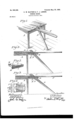
- Figure l is a perspective view of the ironing-board as a whole secured to a table.
- Fig. 2 is a side elevation view of Fig. 1.
- Fig. 3 is a side elevation'view of the board secured to a table, the top of which is in a plane nearer the oor than that shown in Fig. 2..
- Fig. 4 illustrates the top surface of one end of the board and also an end view of the same.
- Fig. 5 is a perspective view of one of the brackets detached from the board.
- the letter A designates a table.
- B is the fulcrum-bar; C, a notch or recess made at one end of the bar.
- D represents a series of holes.
- E is the end of the bar which rests in contact with the floor.
- F is the ironing-board proper, in this instance tapered slightly in shape, as clearly shown in Fig. 1, and Gr is a slot made in one end of the board.
- two metallic brackets On each side of the slot p and parallel 'with it are secured, by screws or rivets, two metallic brackets, each of the form illustrated by Fig. 5.
- the letter H designates a flange extending the entire length of the bracket.
- each lange H of the brackets is made thin or of quite limited thickness, so that when the ironing-board is adjusted and in use the butterliy-nut can be turned and compress the flanges against the fulcrum-bar, which closely and frictionally ⁇ its withnthe slot G of the board.
- the board When the bar is thus compressed between the lianges, the board cannot be raised in a vertical plane or revolved about the bolt J, and consequently there is no liability of the device becoming accidentally detached from its support.
- the surfaces of the flanges in contact with the bar may be roughened or milled.
- Another characteristic feature of theinvention resides in the adjustability of the board and fulcrum-bar each to theother, so that attachment can be made to supports of different thicknesses and such as may be lof cated in different planes or at different heights from the floor.
- Figs. 2 and illustrate the adjustment of the board and bar when attached to relatively high and low supports or tables.
- the bolt J is located in the second hole of the bar and the third hole of the brackets. Should the attempt be made to attach the device to a lower support, as in Fig. 3, the board F would occupy the position shown in dotted lines.
- the bolt By changing the bolt to the third hole of the bar and to the fourth hole of the brack- IOO ets the board is brought to a plane parallel with the floor.
- the formation of the two series of holes-one in the fulcru m-bar and the other in the brackets- provides for the attachment of the ironing-board to a great variety of convenient supports differing in thickness and in height from the floor.
- a fulcrum-bar provided with a series of holes
- a board, as F having brackets provided with a series of holes; each of said brackets having a series of teeth, M, whereby, when the board is adj usted, the same is held against side movement; in substance as set forth.
Landscapes
- Engineering & Computer Science (AREA)
- Textile Engineering (AREA)
- Irons (AREA)
Description
No. 650,366. y Patented May 29, |900. C. W. BLETHEN & F. J. LARSEN.
IRONING BOARD.
(Application filed Feb. 5, 1900.)
(No Model.)
UNITED' STATES PATENT Ormes.
CHARLES XVILLIAM BLETHEN AND FRED JOHN LA RSEN, OF MANNI'NG, f UTAH.
SPECIFICATION forming part of Letters Patent No. 650,366, dated May 29, 1900.
Application filed February 5, 1900. Serial No. 4,133. (No model.)
To all whom, if; may concern,.-
Be it known that we, CHARLES XVILLIAM BLETHEN and FRED JOHN LAnsnN, citizens of the United States, residing at Manning, in the county of Utah and State of Utah, have invented certain new and useful Improvements in Ironing-Boards, of which the following is a specification.
The object of the invention is the production of an ironing-board which can be detachably secured to the edge of a table, a windowsill,'a cleat fastened to the wall, or to any4 other suitable and convenient support, which shall be provided with means for adjusting and locking the parts in their relative positions when in use, which shall positively engage the object to which it is secured, so as to prevent side movement of the board, and which, withal, shall possess other and desirable features and characteristics constituting it a superior device for the purposes intended. WVith the above object or end in view the invention consists in certain novelties of construct-ion and com binations and arrangements of parts hereinafter set forth and claimed.
The accompanying drawings illustrate an example of the physical embodiment of the invention constructed according to the best of the several modes we have so far devised for the application of the principle.
Figure l is a perspective view of the ironing-board as a whole secured to a table. Fig. 2 is a side elevation view of Fig. 1. Fig. 3 is a side elevation'view of the board secured to a table, the top of which is in a plane nearer the oor than that shown in Fig. 2.. Fig. 4 illustrates the top surface of one end of the board and also an end view of the same. Fig. 5 is a perspective view of one of the brackets detached from the board.
Referring to the several figures, the letter A designates a table.
B is the fulcrum-bar; C, a notch or recess made at one end of the bar.
D represents a series of holes.
E is the end of the bar which rests in contact with the floor.
F is the ironing-board proper, in this instance tapered slightly in shape, as clearly shown in Fig. 1, and Gr is a slot made in one end of the board. On each side of the slot p and parallel 'with it are secured, by screws or rivets, two metallic brackets, each of the form illustrated by Fig. 5.
The letter H designates a flange extending the entire length of the bracket.
I represents a series of holes through the f ets, or screws, the end of the board each side of the slot G fitting between the upper and lower plates L N of the bracket. The teeth M project slightly above the plane of the top surface of the plate L, as indicated in the views. Each lange H of the brackets is made thin or of quite limited thickness, so that when the ironing-board is adjusted and in use the butterliy-nut can be turned and compress the flanges against the fulcrum-bar, which closely and frictionally {its withnthe slot G of the board. When the bar is thus compressed between the lianges, the board cannot be raised in a vertical plane or revolved about the bolt J, and consequently there is no liability of the device becoming accidentally detached from its support. To obtain a firmer grip, the surfaces of the flanges in contact with the bar may be roughened or milled.
Another characteristic feature of theinvention resides in the adjustability of the board and fulcrum-bar each to theother, so that attachment can be made to supports of different thicknesses and such as may be lof cated in different planes or at different heights from the floor.
Figs. 2 and illustrate the adjustment of the board and bar when attached to relatively high and low supports or tables. In Fig. 2 the bolt J is located in the second hole of the bar and the third hole of the brackets. Should the attempt be made to attach the device to a lower support, as in Fig. 3, the board F would occupy the position shown in dotted lines. By changing the bolt to the third hole of the bar and to the fourth hole of the brack- IOO ets the board is brought to a plane parallel with the floor. The formation of the two series of holes-one in the fulcru m-bar and the other in the brackets-provides for the attachment of the ironing-board to a great variety of convenient supports differing in thickness and in height from the floor.
From the foregoing it will be obvious that a device has been produced which fulfils all the conditions set forth as the object or end of the invention, besides possessing other desirable and novel characteristics and features.
While there has been illustrated and described only one example of the physical embodiment of the invention, it is not the intention to restrict the scope thereof to such single example, inasmuch as many changes can be introduced and modifications made without constitutinga substantial departn re.
What we claim as new, and desire to secure by Letters Patent, is-
1. The combination in an ironing-board, of a fnlcrum-bar provided with a notch at one end, as C, and a series of holes, as D; aboard, as F, slotted at one end and having attached thereunto on each side of the slot brackets, each provided with a series of holes; and a bolt, as J, provided with a nut, as K; in substance as set forth.
2. The combination in an ironing-board, of-
a fulcrum-bar provided with a series of holes; and a board, as F, having brackets provided with a series of holes; each of said brackets having a series of teeth, M, whereby, when the board is adj usted, the same is held against side movement; in substance as set forth.
3. The combination in an ironing-board, of a fnlcrum-bar and a board proper, as F; the said board being provided with two brackets and each bracket comprising a lieXible flange, H, a plate, N, a plate, L, anda series of teeth, M; in substance as set forth.
In testimony whereof we affix our signatures in presence of two witnesses.
CHARLES WILLTAM BLE'IIIEN. FRED JOHN'LARSEN.
Witnesses W. B. LA VIELLE, LEIGH H. DUNNING.
Priority Applications (1)
| Application Number | Priority Date | Filing Date | Title |
|---|---|---|---|
| US413300A US650366A (en) | 1900-02-05 | 1900-02-05 | Ironing-board. |
Applications Claiming Priority (1)
| Application Number | Priority Date | Filing Date | Title |
|---|---|---|---|
| US413300A US650366A (en) | 1900-02-05 | 1900-02-05 | Ironing-board. |
Publications (1)
| Publication Number | Publication Date |
|---|---|
| US650366A true US650366A (en) | 1900-05-29 |
Family
ID=2718936
Family Applications (1)
| Application Number | Title | Priority Date | Filing Date |
|---|---|---|---|
| US413300A Expired - Lifetime US650366A (en) | 1900-02-05 | 1900-02-05 | Ironing-board. |
Country Status (1)
| Country | Link |
|---|---|
| US (1) | US650366A (en) |
-
1900
- 1900-02-05 US US413300A patent/US650366A/en not_active Expired - Lifetime
Similar Documents
| Publication | Publication Date | Title |
|---|---|---|
| US581681A (en) | Attachment for tables | |
| US650366A (en) | Ironing-board. | |
| US493605A (en) | John n | |
| US773972A (en) | Adjustable support. | |
| US1202589A (en) | Picture-frame. | |
| US830232A (en) | Adjustable bracket. | |
| US1083763A (en) | Single-piece shelf-bracket. | |
| US910993A (en) | Adjustable seat. | |
| US615130A (en) | Drawing-table | |
| US541653A (en) | Adjustable support for furniture | |
| US1213641A (en) | Supporting device for ironing-boards, &c. | |
| US1423951A (en) | Pedestal | |
| US344269A (en) | Signor of-two-thirds to george dayeluy | |
| US140623A (en) | Improvement in table dish-stands | |
| US533046A (en) | Combined drawing-board and holder | |
| US568397A (en) | Furniture-leg attachment | |
| US144028A (en) | Improvement in billiard-table levelers | |
| US652590A (en) | Radiator-support. | |
| US731278A (en) | Ironing-board. | |
| US646781A (en) | Table-adjuster. | |
| US731879A (en) | Tripod. | |
| USD30460S (en) | Design for a toilet-case | |
| US908653A (en) | Combined school seat and desk. | |
| US138728A (en) | Improvement in book-rests for desks | |
| US990671A (en) | Display-rack. |