US6490040B1 - Fume sensor system and methods for background noise suppression - Google Patents
Fume sensor system and methods for background noise suppression Download PDFInfo
- Publication number
- US6490040B1 US6490040B1 US09/637,717 US63771700A US6490040B1 US 6490040 B1 US6490040 B1 US 6490040B1 US 63771700 A US63771700 A US 63771700A US 6490040 B1 US6490040 B1 US 6490040B1
- Authority
- US
- United States
- Prior art keywords
- lens
- plano
- fume
- fiber optic
- sensor system
- Prior art date
- Legal status (The legal status is an assumption and is not a legal conclusion. Google has not performed a legal analysis and makes no representation as to the accuracy of the status listed.)
- Expired - Lifetime, expires
Links
- 239000003517 fume Substances 0.000 title claims abstract description 99
- 238000000034 method Methods 0.000 title description 11
- 230000001629 suppression Effects 0.000 title 1
- 239000000835 fiber Substances 0.000 claims description 30
- 230000003287 optical effect Effects 0.000 claims description 12
- 238000012545 processing Methods 0.000 claims description 10
- 238000001914 filtration Methods 0.000 claims description 7
- 238000001816 cooling Methods 0.000 claims description 5
- 239000002245 particle Substances 0.000 description 61
- 239000000523 sample Substances 0.000 description 26
- 238000011084 recovery Methods 0.000 description 19
- 239000002655 kraft paper Substances 0.000 description 15
- 239000003546 flue gas Substances 0.000 description 12
- HEMHJVSKTPXQMS-UHFFFAOYSA-M Sodium hydroxide Chemical compound [OH-].[Na+] HEMHJVSKTPXQMS-UHFFFAOYSA-M 0.000 description 9
- CDBYLPFSWZWCQE-UHFFFAOYSA-L Sodium Carbonate Chemical compound [Na+].[Na+].[O-]C([O-])=O CDBYLPFSWZWCQE-UHFFFAOYSA-L 0.000 description 8
- 241001062472 Stokellia anisodon Species 0.000 description 8
- 238000002485 combustion reaction Methods 0.000 description 8
- 238000013461 design Methods 0.000 description 7
- 238000005259 measurement Methods 0.000 description 7
- 239000013307 optical fiber Substances 0.000 description 7
- 230000008569 process Effects 0.000 description 7
- UGFAIRIUMAVXCW-UHFFFAOYSA-N Carbon monoxide Chemical compound [O+]#[C-] UGFAIRIUMAVXCW-UHFFFAOYSA-N 0.000 description 6
- 238000001514 detection method Methods 0.000 description 6
- 239000007832 Na2SO4 Substances 0.000 description 5
- PMZURENOXWZQFD-UHFFFAOYSA-L Sodium Sulfate Chemical compound [Na+].[Na+].[O-]S([O-])(=O)=O PMZURENOXWZQFD-UHFFFAOYSA-L 0.000 description 5
- 229910052938 sodium sulfate Inorganic materials 0.000 description 5
- 230000005540 biological transmission Effects 0.000 description 4
- VDQVEACBQKUUSU-UHFFFAOYSA-M disodium;sulfanide Chemical compound [Na+].[Na+].[SH-] VDQVEACBQKUUSU-UHFFFAOYSA-M 0.000 description 4
- 239000011368 organic material Substances 0.000 description 4
- 239000002243 precursor Substances 0.000 description 4
- VYPSYNLAJGMNEJ-UHFFFAOYSA-N silicon dioxide Inorganic materials O=[Si]=O VYPSYNLAJGMNEJ-UHFFFAOYSA-N 0.000 description 4
- 229910000029 sodium carbonate Inorganic materials 0.000 description 4
- 238000000149 argon plasma sintering Methods 0.000 description 3
- 230000008901 benefit Effects 0.000 description 3
- 238000010411 cooking Methods 0.000 description 3
- 238000009826 distribution Methods 0.000 description 3
- 230000000694 effects Effects 0.000 description 3
- 239000007789 gas Substances 0.000 description 3
- 229910010272 inorganic material Inorganic materials 0.000 description 3
- 229920005610 lignin Polymers 0.000 description 3
- 230000035515 penetration Effects 0.000 description 3
- 239000010453 quartz Substances 0.000 description 3
- 229910052979 sodium sulfide Inorganic materials 0.000 description 3
- 239000000126 substance Substances 0.000 description 3
- ZLMJMSJWJFRBEC-UHFFFAOYSA-N Potassium Chemical compound [K] ZLMJMSJWJFRBEC-UHFFFAOYSA-N 0.000 description 2
- 229920001131 Pulp (paper) Polymers 0.000 description 2
- 239000007864 aqueous solution Substances 0.000 description 2
- 238000010586 diagram Methods 0.000 description 2
- 238000011156 evaluation Methods 0.000 description 2
- 230000005284 excitation Effects 0.000 description 2
- 150000002484 inorganic compounds Chemical class 0.000 description 2
- 238000004519 manufacturing process Methods 0.000 description 2
- 239000000203 mixture Substances 0.000 description 2
- 239000000123 paper Substances 0.000 description 2
- 229910052700 potassium Inorganic materials 0.000 description 2
- 239000011591 potassium Substances 0.000 description 2
- 239000012716 precipitator Substances 0.000 description 2
- 230000005855 radiation Effects 0.000 description 2
- 239000004576 sand Substances 0.000 description 2
- 150000003388 sodium compounds Chemical class 0.000 description 2
- 239000007787 solid Substances 0.000 description 2
- 229910001220 stainless steel Inorganic materials 0.000 description 2
- 239000010935 stainless steel Substances 0.000 description 2
- 238000005406 washing Methods 0.000 description 2
- 239000002023 wood Substances 0.000 description 2
- VEXZGXHMUGYJMC-UHFFFAOYSA-M Chloride anion Chemical compound [Cl-] VEXZGXHMUGYJMC-UHFFFAOYSA-M 0.000 description 1
- 238000003915 air pollution Methods 0.000 description 1
- 238000004458 analytical method Methods 0.000 description 1
- 230000002238 attenuated effect Effects 0.000 description 1
- 238000007664 blowing Methods 0.000 description 1
- 238000004364 calculation method Methods 0.000 description 1
- 230000008859 change Effects 0.000 description 1
- 150000003841 chloride salts Chemical class 0.000 description 1
- 238000004140 cleaning Methods 0.000 description 1
- 230000001427 coherent effect Effects 0.000 description 1
- 230000001419 dependent effect Effects 0.000 description 1
- 239000010432 diamond Substances 0.000 description 1
- 229910003460 diamond Inorganic materials 0.000 description 1
- 238000005553 drilling Methods 0.000 description 1
- 238000001704 evaporation Methods 0.000 description 1
- 230000008020 evaporation Effects 0.000 description 1
- 238000011990 functional testing Methods 0.000 description 1
- 239000005350 fused silica glass Substances 0.000 description 1
- 238000012625 in-situ measurement Methods 0.000 description 1
- 238000011065 in-situ storage Methods 0.000 description 1
- 238000013101 initial test Methods 0.000 description 1
- 239000011147 inorganic material Substances 0.000 description 1
- 238000003780 insertion Methods 0.000 description 1
- 230000037431 insertion Effects 0.000 description 1
- 238000009434 installation Methods 0.000 description 1
- 239000000463 material Substances 0.000 description 1
- 238000012986 modification Methods 0.000 description 1
- 230000004048 modification Effects 0.000 description 1
- 238000012544 monitoring process Methods 0.000 description 1
- 239000013308 plastic optical fiber Substances 0.000 description 1
- 150000003112 potassium compounds Chemical class 0.000 description 1
- 238000004537 pulping Methods 0.000 description 1
- 238000010926 purge Methods 0.000 description 1
- 230000009467 reduction Effects 0.000 description 1
- 239000011347 resin Substances 0.000 description 1
- 229920005989 resin Polymers 0.000 description 1
- 239000000243 solution Substances 0.000 description 1
- 239000007921 spray Substances 0.000 description 1
- 238000002834 transmittance Methods 0.000 description 1
- 230000000007 visual effect Effects 0.000 description 1
- 239000003039 volatile agent Substances 0.000 description 1
- XLYOFNOQVPJJNP-UHFFFAOYSA-N water Substances O XLYOFNOQVPJJNP-UHFFFAOYSA-N 0.000 description 1
Images


Classifications
-
- G—PHYSICS
- G01—MEASURING; TESTING
- G01N—INVESTIGATING OR ANALYSING MATERIALS BY DETERMINING THEIR CHEMICAL OR PHYSICAL PROPERTIES
- G01N21/00—Investigating or analysing materials by the use of optical means, i.e. using sub-millimetre waves, infrared, visible or ultraviolet light
- G01N21/17—Systems in which incident light is modified in accordance with the properties of the material investigated
- G01N21/47—Scattering, i.e. diffuse reflection
- G01N21/49—Scattering, i.e. diffuse reflection within a body or fluid
- G01N21/53—Scattering, i.e. diffuse reflection within a body or fluid within a flowing fluid, e.g. smoke
-
- G—PHYSICS
- G01—MEASURING; TESTING
- G01N—INVESTIGATING OR ANALYSING MATERIALS BY DETERMINING THEIR CHEMICAL OR PHYSICAL PROPERTIES
- G01N21/00—Investigating or analysing materials by the use of optical means, i.e. using sub-millimetre waves, infrared, visible or ultraviolet light
- G01N21/17—Systems in which incident light is modified in accordance with the properties of the material investigated
- G01N21/47—Scattering, i.e. diffuse reflection
- G01N2021/4704—Angular selective
- G01N2021/4709—Backscatter
Definitions
- the present invention relates generally to Kraft recovery boilers used in the pulp and paper industry and, in particular, to a fume sensor system that measures the concentration of fume particles produced during combustion of black liquor in such Kraft recovery boilers.
- the black liquor rinsed from the pulp in the washers is an aqueous solution containing wood lignin, organic material and inorganic compounds oxidized in the cooking process.
- the Kraft cycle processes this liquor through a series of operations, including evaporation, combustion of organic materials, reduction of the spent inorganic compounds, and reconstitution of the white liquor.
- the Kraft recovery boiler furnace was specially designed to combust the black liquor organic material while, reducing the oxidized inorganic material in a pile, or bed, supported by the furnace floor.
- the molten inorganic chemicals or smelt in the bed are discharged to a tank and dissolved to form green liquor.
- Green liquor active chemicals are Na 2 CO 3 and Na 2 S.
- the black liquor solution which contains these sodium compounds and combustible lignin, leaves the digester along with the wood pulp.
- the residual water is evaporated and the organic material is combusted.
- Approximately 45% by weight of the dry, as-fired solids is inorganic ash, and the majority of these inorganics are removed from the furnace as Na 2 S and Na 2 CO 3 in the molten smelt.
- a significant amount of the ash is present as particulate entrained in the existing flue gases; generally, about 8% by weight of the entering black liquor solids leaves the furnace as ash.
- Ash is generally categorized as fume or carryover.
- Carryover consists of char particles and black liquor droplets that are swept away from the char bed and liquor spray by the upward flue gas flow.
- Fume consists of volatile sodium compounds and potassium compounds, and it is vaporous in the combustion zone such that it is entrained in the flue gas and rises into the convection sections of recovery boilers. Since these volatiles condense into submicron particles that deposit onto the superheater, boiler bank, and economizer surfaces, it is desirable to minimize the amount of fume produced. The rate of fume production depends on local temperature within and above the smelt bed as well as the temperature distribution on the surface of the smelt bed. Fume particles in Kraft recovery boilers are usually 0.25 to 1.0 ⁇ m (microns) in diameter and consist primarily of Na 2 SO 4 and a much lower content of Na 2 CO 3 . Fume also contains potassium and chloride salts.
- Fume which exits the recovery boiler furnace and makes its way into the convection pass of the recovery boiler is a major source of deposits on the steam generator tubing located within the convection pass.
- the fume deposits are generally removed by sootblowing. At temperatures below 600° F., the fume deposits slowly sinter on the tubes. At 900° F., the fume deposits sinter quickly and may harden and become resistant to sootblowing within an hour. If there are large amounts of carryover particles in the flue gas, these carryover particles can impact and become embedded in the fume deposits on the tubing. To avoid plugging, it is desirable to minimize production of both fume particles and carryover particles and to maintain good control of the furnace exit gas temperature of the Kraft recovery boiler.
- the capability to make continuous, real-time, in-situ measurements of fume concentration in a Kraft recovery boiler has many potential benefits, including the ability to: (a) confirm the proper smelt bed temperature profile; (b) warn of potential hot spots in the smelt bed; (c) provide an alarm when excessive fume concentrations exist in the convection pass so that the sootblower cleaning system can be activated; (d) track fume concentration in the convection pass to improve overall fume collection efficiency, reduce fume particulate emissions, and recover the maximum amount of Na 2 SO 4 for return to the liquor cycle in the Kraft process; and (e) provide a control signal to automatically add new Na 2 SO 4 to the process.
- one aspect of the present invention is drawn to a fume sensor system for measuring a concentration of fume particles produced during combustion of black liquor in Kraft recovery boilers.
- the main components of the fume sensor system according to the invention comprise: a fume sensor probe housing for insertion into an upper furnace region of the Kraft recovery boiler; laser means for producing collimated light which is projected into the furnace flue gases to interrogate same, objective lens means for projecting the collimated light from the laser means into the flue gases and receiving backscattered light from fume particles in the flue gases; light detection means for detecting backscattered light collected by the objective lens means and producing electrical signals indicative thereof; optical fiber means for conveying light between the laser means, the objective lens means, and the light detection means; and signal processing means for processing the electrical signals representative of the received backscattered light to produce signals representative of fume particle concentration in the flue gas.
- the present invention relies upon the fact that the backscattered light intensity from submicron size fume particles is independent of the particle size and particle size distribution. This aspect is illustrated in FIG. 6 . While carryover particles are also present in the furnace flue gases, those carryover particles are much larger in size (typically 5 to 100 ⁇ m in size) and less numerous than the fume particles (typically 0.25 to 1 ⁇ m in size). Thus, these particles may be easily discriminated.
- another aspect of the present invention is drawn to noise discrimination by providing a combination of modulating the signal of interest and filtering the background noise with a narrow bandpass optical filter to reduce the background light in the fume sensor and prevent detector saturation.
- Yet another aspect of the present invention is drawn to a hybrid objective lens assembly for a fume sensor probe comprising a plano-convex lens (needed for light collection) which is provided with a cylindrical graded index lens (needed for light projection).
- the hybrid objective lens assembly projects a light beam into the furnace, collects backscattered light from the fume particles in the furnace flue gas, and focuses the light into an optical fiber.
- a separate fiber may be used to deliver the laser light to the fume sensor probe.
- An important feature of the present invention involves the use of spatial filtering to discriminate against backscattered light from non-representative particle concentrations near the recovery boiler furnace walls.
- FIG. 1 is a schematic representation of a conceptual design of a fume sensor system
- FIG. 2 is a schematic block diagram of the fume sensor system of FIG. 1;
- FIG. 3 is a schematic representation of a revised conceptual design of a fume sensor system according to the present invention.
- FIG. 4 is a schematic sectional view of a suggested precursor assembly for the hybrid objective lens assembly used in the present invention.
- FIG. 5 is a schematic sectional view of a hybrid lens assembly for use in the fume sensor system of FIG. 3;
- FIG. 6 is a graph of backscattered light power versus particle size
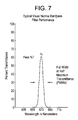
- FIG. 7 is a graph of percent transmittance versus wavelength in nanometers which illustrates typical visual narrow bandpass filter performance.
- the typical fume concentration at a recovery boiler outlet is 2.6 grains per SCF, which is about 4.8 g/m 3 .
- the sensor could be used to measure fume at the precipitator outlet to monitor the precipitator's performance. In this location, the fume concentration may be much less than 5 g/m 3 . Thus, any fume sensor must be able to measure fume concentration in the range 0 to 5 g/m 3 .
- the particle number density is about 5.8 ⁇ 10 14 particles/m 3 . If we assume that all the particles are the minimum size (0.25 ⁇ m), the maximum particle number density increases to 3.7 ⁇ 10 16 particles/m 3 . Although the estimated particle number density range is large, it is measurable using light scattering methods.
- 2200 nW of power would be transmitted through a 1 meter distance, and the laser beam could penetrate 1.2 meters (only an additional 0.2 meters) before being attenuated to 600 nW.
- the calculated two-way penetration depth for these two extremes in opacity is essentially the same. In practice, 10 ⁇ 6 nW of optical power is detectable, and with a 1 mW source, the maximum estimated penetration depth would be about 3 meters.
- the light scattering signal of interest is produced by fume particles in the size range 0.25 to 1 m, it is important to recognize and reject light scattering signals from the much larger carryover particles.
- Background light is present in the furnace and results from combustion radiation.
- a detector for converting light power has a limited dynamic range, however, and if the background light is sufficiently intense, it will saturate the detector and the detector output current signal.
- FIGS. 1 and 2 designate the same or functionally similar elements
- FIG. 3 is a schematic representation of a revised conceptual design according to the present invention which overcomes certain problems encountered with the design of FIGS. 1 and 2.
- fume sensor system 10 comprises a probe housing 12 adapted for mounting through a furnace wall 14 so as to view the gases within a furnace 16 of a Kraft recovery boiler which contains fume particles 8 .
- a front end 20 of the probe 12 is provided with a sacrificial quartz window 22 which is protected by a tangential air curtain 24 blowing there across.
- Cooling/purge air 26 such as instrument air, may be provided at a rear end 28 of probe housing 12 and conveyed along an annular region 30 thereof to produce the air curtain 24 and also to cool the probe housing 12 .
- An objective lens 32 is provided within the probe housing 12 and behind the quartz window 22 .
- objective lens 32 projects a light beam into the fume particles 18 within the furnace 16 , collects backscattered light from the fume particles 18 , and focuses the collected backscattered light into optical fiber 34 which was used to convey the light to the objective lens 32 .
- Optical fiber 34 is operatively connected to one or two miniature diode lasers 36 , 38 which provide light beams for projection into the furnace flue gases and their entrained fume particles 18 .
- Diode lasers 36 , 38 are remotely located in a cool zone to protect them and are powered by a modulated power supply 39 .
- the first conceptual design envisioned the potential usefulness of two diode lasers 36 , 38 (one operating at a different frequency than the other or, in the alternative, one operating 180° out of phase with the other) to extend the measurement range of fume concentration, discriminate against carryover particles, and reduce errors from wall effects.
- one or two photodiode detectors 40 and associated preamplifiers might be provided to receive the backscattered light collected by the objective lens 32 after it is delivered through the optical fiber 34 and a power splitter 42 .
- Each photodiode detector 40 would convert the light power into a proportional electrical photocurrent, which is conveyed via line(s) 44 to detection electronics and signal processing means 46 , also located at a remote, relatively cool location.
- Signal processing means 46 would most preferably contain analog to digital (A/D) converters and multiplexing means 48 for selecting among various input signals (possibly from other probe housings 12 ) and means for sending an output signal indicative of the fume concentration to a local digital display 50 , to a main control room 52 , or as an output along an RS232/RS422 line to recording devices or control elements 54 used to vary parameters associated with the Kraft recovery boiler combustion process and adjust the fume particles 18 concentration in the furnace 16 .
- A/D analog to digital
- Signal processing means 46 could also receive a signal representative of a temperature of the probe housing 12 via probe temperature signal line 56 from a temperature sensor 58 located within the probe housing 12 .
- signal processing means 46 can be any of a variety of systems, including but not limited to A/D and microprocessors, output recording devices, local digital displays, control room displays and/or control elements, or any other analog or digital recording or display devices.
- FIG. 6 is a graph of backscattered light power versus particle size (taken from F. M. Shofner et al., “In Situ Continuous Measurement of Particle Mass Concentration”, 68th Annual Meeting of the Air Pollution Control Association, Boston, Mass., 1975), over the size range of 0:25 ⁇ m to 1.0 ⁇ m, the backscattered light power is essentially independent of particle size.
- the fume sensor system according to the present invention is based upon this convenient circumstance. Even if carryover particles are present in the flue gas, they are much larger (5 to 100 ⁇ m) and have been determined empirically to be much fewer in number. Thus, these carryover particles produce large, short duration pulses which can be electronically filtered out, and it becomes easy to distinguish fume particles from carryover particles on the basis of size.
- a single diode laser 36 (rather than two) was used (a Coherent Auburn Model VLM) during the evaluation of the invention as embodied in FIGS. 1 and 2.
- the laser 36 contained built-in modulating circuitry and the nominal operating wavelength was approximately 670 nanometers (rum).
- the probe assembly was contained within a modified probe housing used in a Carryover Monitoring System (CMS) made by Diamond Power International.
- CMS Carryover Monitoring System
- FIG. 3 illustrates the present configuration of the fume sensor system according to the preferred embodiment of the present invention, generally designated 100 .
- This system overcame the aforementioned problem encountered in FIGS. 1 and 2 and provided additional advantages.
- FIG. 3 demonstrates a modification of the embodiment of FIGS. 1 and 2, the inventors anticipate that those skilled will be able to modify the embodiment of FIGS. 1 and 2, without departing from the invention described herein, using similar techniques, and the principles which underlie these techniques, to those described in FIG. 3 .
- like reference numerals designate the same or functionally similar elements.
- the splitter/coupler 42 was eliminated, and two optical fibers were used—a 50 ⁇ m diameter core/125 ⁇ m diameter clad fiber (50/125) for light delivery and a 550 ⁇ m diameter core/600 ⁇ m diameter clad fiber (550/600) for scattered light collection.
- An additional plastic optical fiber with large core and large numerical aperture (NA) is inserted into the laser mount assembly to collect a small sample of scattered laser light near the laser output, and this light is delivered to a reference detector D R .
- a modified hybrid objective lens assembly for use with these two separate optical fibers was created as illustrated in FIGS. 4 and 5, infra, and a very narrowband optical filter means is employed to prevent detector saturation.
- the fume sensor system 100 is again provided with an air cooled probe housing 12 which cooling air also serves to provide a tangential air curtain 24 in front of a sacrificial quartz window 22 .
- the fume sensor probe housing 12 can thus be inserted through the furnace wall 14 into an upper furnace 16 region of the recovery boiler and resists fouling, while protecting and maintaining the alignment of the optical components.
- the fume sensor probe housing 12 is again preferably cooled and purged with instrument air 26 ; however, in principle a stainless steel probe tip and fused silica objective lens and window could withstand a 1600 F furnace gas environment without cooling.
- a hybrid objective lens assembly 110 is provided.
- a precursor assembly 108 is depicted in FIG. 4, and the entire hybrid objective lens assembly 110 is seen in FIG. 5.
- a single objective lens with a thickness equal to L 1 +L 2 could also be used instead of a separate piano-convex lens and plano-plano lens (also referred to as a “window”).
- precursor assembly 108 is advantageously a plano-convex lens comprised of a 40 mm focal length (FL) lens 112 (e.g., a Melles Griot 01LPX079) having a hole 114 and a plano-plano lens 116 (e.g., a Melles Griot 02WBK221) having a hole 118 .
- FL focal length
- precursor holes 114 and 118 are concentrically drilled and oriented, further keeping in mind that FIG. 4 represents only one of a variety of ways in which one skilled in the art may ultimately assemble the hybrid objective lens assembly pictured in FIG. 5 .
- the entire assembly has the following dimensions: lens 112 has a length, L 2 , of 2.6 mm; plano-plano lens 116 has a length, L 1 , of 6 mm; hole 118 could be tapered, starting at a length, L 3 , that is 4.6 mm from the apex of lens 112 , and hole 118 has a diameter, D 1 , of 0.099 inches at its largest point; hole 114 has a diameter, D 2 , of 0.071 inches.
- all aforementioned dimensions are merely optimal suggestions, and it is expected that those skilled in the art will readily adapt the dimensions to suit their various circumstances.
- FIG. 5 shows the hybrid objective lens assembly 110 , which advantageously comprises a piano-convex lens comprised of a 40 mm focal length (FL), light collection lens 112 (e.g., a Melles Griot 01LPX079) having a hole 114 and a plano-plano lens 116 (e.g., a Melles Griot 02WBK221) having a hole 118 ; a cylindrical graded index microlens 120 (e.g., an NSG SELFOC SLW-180-025-630-NCO); and a stainless steel ferrule 122 from an ST style fiber optic connector.
- FL 40 mm focal length
- light collection lens 112 e.g., a Melles Griot 01LPX079
- plano-plano lens 116 e.g., a Melles Griot 02WBK221
- a cylindrical graded index microlens 120 e.g., an NSG SELFOC SLW-180-025-630-NCO
- the purpose for the ST ferrule 122 is to provide a precision holder for a light delivery fiber 124 and to center the fiber 124 onto the cylindrical graded index microlens 120 .
- the hybrid objective lens assembly 110 may be produced by drilling the holes 114 , 118 (as suggested above) into the plano-convex lens (needed for light collection), and inserting the cylindrical graded index microlens 120 needed for light collimation into the drilled hole 114 . Holes 114 and 118 must be coaxial. All these components are cemented 126 with Norland NOA61 transparent UV cure resin, or similar material.
- a tip 128 of the light delivery fiber 124 (e.g., a Spectran TCUME050H) is bonded to the ST ferrule 122 and is in contact with the cylindrical graded index microlens 120 .
- the hybrid objective lens assembly 110 is designed to function as follows.
- the SELFOC graded index microlens projects a collimated beam with a full diameter of 8 inches (4 inch diameter where the power has fallen to 1/e of maximum value) at 37 feet from the probe tip.
- the 40 mm FL lens 112 collects light scattered by fume particles 18 in the beam path, and focuses the light into the 0.6 mm diameter scattered light collection fiber 130 .
- the 0.6 mm diameter scattered light collection fiber 130 also performs a spatial filtering function, since the scattered light from particles at distances beyond 3 feet from the probe tip is coupled more efficiently into the scattered light collection fiber 130 than the light scattered by particles within 3 feet of the probe tip.
- a very narrowband optical filter F is inserted between the signal detector D s and the scattered light collection fiber 130 .
- the filter F bandwidth is chosen wide enough to cover the tolerance uncertainty in the wavelength of laser 36 , but narrow enough to reject all background light except the negligible amount of background which passes through the filter F.
- the transmission characteristic of such a filter F is shown in FIG. 7 .
- These filters are commercially available.
- the laser emission wavelength was 674 nm. Both the laser emission wavelength and the peak wavelength of the filter F transmission characteristic change with temperature.
- a filter F with a 10 nm bandwidth (FWHM) is sufficient to handle the temperature dependent wavelength uncertainties.
- Filter F which is part of signal detector 40 , then receives backscattered light 21 , created from reflections of excitation beam 19 .
- Backscattered light 21 is, in turn, conveyed back from the furnace 16 via scattered light collection fiber 130 .
- Filter F is selected to filter out and reject background light noise (e.g., signals and light generated by carryover particles, instead of fume particles).
- Signal detector D s associated with filter F converts the backscattered light 21 into a proportional electrical photocurrent, which is conveyed along line 44 to the detection electronics and signal processing means 46 where it is amplified and processed as before.
- Reference detector D R produces a reference signal which is conveyed along line 47 to the detection electronics and signal processing means 46 where it is also amplified and processed.
- the laser 36 is modulated to discriminate between the backscattered light (which is also modulated) and unmodulated background light.
- the background light is present in the furnace 16 and results from combustion radiation.
- the signal detector D s has a limited dynamic range, however, and if the background light is sufficiently intense it will saturate the signal detector D s and the detector output signal.
- the scattered light collection fiber 130 also performs a spatial filtering function.
- the scattered light from fume particles 18 at distances beyond three feet from the probe tip is coupled more efficiently into the scattered light collection fiber 130 than the light scattered by fume particles 18 within three feet of the probe tip.
- noise discrimination is provided by a combination of modulating the signal of interest, filtering the background noise with a narrow bandpass optical filter, and spatial filtering of the collected signal.
Abstract
Description
| Approximate 1/e beam diameter 37 feet from | 4 | inches |
| lens | ||
| Angular deviation of collimated beam from | 1 | degree |
| optical axis of assembly | ||
| Laser power measured at SELFOC lens | 3.5 | dBm (2.2 milliwatt) |
| output | ||
| Laser background noise measured at out- | −60 | dBm (1 nanowatt). |
| put of 0.6 mm collection fiber | ||
Claims (10)
Priority Applications (1)
| Application Number | Priority Date | Filing Date | Title |
|---|---|---|---|
| US09/637,717 US6490040B1 (en) | 2000-08-11 | 2000-08-11 | Fume sensor system and methods for background noise suppression |
Applications Claiming Priority (1)
| Application Number | Priority Date | Filing Date | Title |
|---|---|---|---|
| US09/637,717 US6490040B1 (en) | 2000-08-11 | 2000-08-11 | Fume sensor system and methods for background noise suppression |
Publications (1)
| Publication Number | Publication Date |
|---|---|
| US6490040B1 true US6490040B1 (en) | 2002-12-03 |
Family
ID=24557087
Family Applications (1)
| Application Number | Title | Priority Date | Filing Date |
|---|---|---|---|
| US09/637,717 Expired - Lifetime US6490040B1 (en) | 2000-08-11 | 2000-08-11 | Fume sensor system and methods for background noise suppression |
Country Status (1)
| Country | Link |
|---|---|
| US (1) | US6490040B1 (en) |
Cited By (7)
| Publication number | Priority date | Publication date | Assignee | Title |
|---|---|---|---|---|
| US20040057493A1 (en) * | 2002-07-15 | 2004-03-25 | Chuji Ishikawa | Temperature detecting unit and fixing apparatus |
| US20050067588A1 (en) * | 2003-09-26 | 2005-03-31 | Ishikawajima-Harima Heavy Industries Co., Ltd. | Purge air flow passage structure |
| US20080246965A1 (en) * | 2007-03-23 | 2008-10-09 | Rick Miller | Optical Particle Sensor with Exhaust-Cooled Optical Source |
| DE102008017412A1 (en) * | 2008-04-03 | 2009-10-15 | Von Ardenne Anlagentechnik Gmbh | Optical sensor for use in coating system i.e. physical vapor deposition system, has nozzle attached to optical receiver for directing gas flow to receiver, and optical transmitter for transmitting optical signal |
| US20110026023A1 (en) * | 2009-07-31 | 2011-02-03 | GENERAL IMPIANTI S.r.I.. | Method and apparatus for determining size and composition of a particulate matter in a fume flow |
| WO2018089474A1 (en) * | 2016-11-11 | 2018-05-17 | Carrier Corporation | High sensitivity fiber optic based detection |
| US10359350B1 (en) * | 2018-01-23 | 2019-07-23 | Hai Lin | Method and system for particle characterization in harsh environments |
Citations (5)
| Publication number | Priority date | Publication date | Assignee | Title |
|---|---|---|---|---|
| US5155549A (en) * | 1990-10-25 | 1992-10-13 | The Research Of State University Of New York | Method and apparatus for determining the physical properties of materials using dynamic light scattering techniques |
| US5298969A (en) * | 1989-09-05 | 1994-03-29 | The University Of Akron | Combined optical train for laser spectroscopy |
| US5444530A (en) * | 1993-06-07 | 1995-08-22 | Scientific Technology, Inc. | Weather identifier and visibility sensor |
| US5953120A (en) * | 1996-01-04 | 1999-09-14 | Sandia Corporation | Optical probe |
| US6084670A (en) * | 1997-03-11 | 2000-07-04 | Nihon Kohden Corporation | Particle analyzer and composite lens formed by integrally joining plural lens elements of different focal points |
-
2000
- 2000-08-11 US US09/637,717 patent/US6490040B1/en not_active Expired - Lifetime
Patent Citations (5)
| Publication number | Priority date | Publication date | Assignee | Title |
|---|---|---|---|---|
| US5298969A (en) * | 1989-09-05 | 1994-03-29 | The University Of Akron | Combined optical train for laser spectroscopy |
| US5155549A (en) * | 1990-10-25 | 1992-10-13 | The Research Of State University Of New York | Method and apparatus for determining the physical properties of materials using dynamic light scattering techniques |
| US5444530A (en) * | 1993-06-07 | 1995-08-22 | Scientific Technology, Inc. | Weather identifier and visibility sensor |
| US5953120A (en) * | 1996-01-04 | 1999-09-14 | Sandia Corporation | Optical probe |
| US6084670A (en) * | 1997-03-11 | 2000-07-04 | Nihon Kohden Corporation | Particle analyzer and composite lens formed by integrally joining plural lens elements of different focal points |
Cited By (12)
| Publication number | Priority date | Publication date | Assignee | Title |
|---|---|---|---|---|
| US20040057493A1 (en) * | 2002-07-15 | 2004-03-25 | Chuji Ishikawa | Temperature detecting unit and fixing apparatus |
| US20050067588A1 (en) * | 2003-09-26 | 2005-03-31 | Ishikawajima-Harima Heavy Industries Co., Ltd. | Purge air flow passage structure |
| US7091470B2 (en) * | 2003-09-26 | 2006-08-15 | Ishikawajima-Harima Heavy Industries Co., Ltd. | Purge air flow passage structure |
| US20080246965A1 (en) * | 2007-03-23 | 2008-10-09 | Rick Miller | Optical Particle Sensor with Exhaust-Cooled Optical Source |
| US7796255B2 (en) | 2007-03-23 | 2010-09-14 | Particle Measuring Systems, Inc. | Optical particle sensor with exhaust-cooled optical source |
| DE102008017412A1 (en) * | 2008-04-03 | 2009-10-15 | Von Ardenne Anlagentechnik Gmbh | Optical sensor for use in coating system i.e. physical vapor deposition system, has nozzle attached to optical receiver for directing gas flow to receiver, and optical transmitter for transmitting optical signal |
| DE102008017412B4 (en) * | 2008-04-03 | 2012-03-22 | Von Ardenne Anlagentechnik Gmbh | Coating plant and method for cleaning an optical sensor of the coating plant |
| US20110026023A1 (en) * | 2009-07-31 | 2011-02-03 | GENERAL IMPIANTI S.r.I.. | Method and apparatus for determining size and composition of a particulate matter in a fume flow |
| US8013995B2 (en) * | 2009-07-31 | 2011-09-06 | General Impianti S.R.L. | Method and apparatus for determining size and composition of a particulate matter in a fume flow |
| WO2018089474A1 (en) * | 2016-11-11 | 2018-05-17 | Carrier Corporation | High sensitivity fiber optic based detection |
| US10943449B2 (en) | 2016-11-11 | 2021-03-09 | Carrier Corporation | High sensitivity fiber optic based detection |
| US10359350B1 (en) * | 2018-01-23 | 2019-07-23 | Hai Lin | Method and system for particle characterization in harsh environments |
Similar Documents
| Publication | Publication Date | Title |
|---|---|---|
| US4249244A (en) | Electro-optical system and method and apparatus for providing automatically-compensating, traceable calibration and zeroing for light scattering devices | |
| JP5078099B2 (en) | Optical fiber device for detecting light scattering to differentiate blood cells and the like | |
| CN101201315B (en) | Probe | |
| AU2008201027B2 (en) | Smoke detector | |
| RU2377573C2 (en) | Optical flow metre for measuring flow of gases and liquids in pipes | |
| US4890920A (en) | In situ particle size measuring device | |
| US6490040B1 (en) | Fume sensor system and methods for background noise suppression | |
| EP2265407B1 (en) | Process monitoring | |
| EP1284419B1 (en) | Light scattering fume sensor | |
| NO337240B1 (en) | Optical transit time speedometer | |
| KR20120013297A (en) | Method and system for analysing solid particles in a medium | |
| FR2611905A1 (en) | DEVICE FOR MEASURING, IN REAL-TIME, THE CONTENT OF A GAS IN AEROSOL | |
| JP4987515B2 (en) | smoke detector | |
| JP2005536741A (en) | Apparatus for detecting backscatter in laser-based blood analysis systems | |
| WO2021097910A1 (en) | Detection device and method for tiny particles in liquid | |
| JP2001272259A (en) | Flowmeter | |
| CN111665173A (en) | Forward scattering type dust concentration measuring instrument | |
| JP2740262B2 (en) | Particle size measurement smoke detector | |
| EP0256120B1 (en) | An in situ particle size measuring device cross-reference to related applications | |
| CN1409116A (en) | Pipeline powder coal on-line monitor | |
| US4396286A (en) | Electro-optical system and method and apparatus for providing automatically-compensating, traceable calibration and zeroing for light scattering devices | |
| AU7057291A (en) | Method and device for detection of particles in flowing media | |
| SU1543979A1 (en) | Laser-type particle counter | |
| Partin | Development of Optical Technologies for Monitoring Moisture and Particulate in Geothermal Steam | |
| JPH09270084A (en) | Particular detector |
Legal Events
| Date | Code | Title | Description |
|---|---|---|---|
| AS | Assignment |
Owner name: MCDERMOTT TECHNOLOGY, INC., LOUISIANA Free format text: ASSIGNMENT OF ASSIGNORS INTEREST;ASSIGNORS:BERTHOLD, JOHN W.;JEFFERS, LARRY A.;REEL/FRAME:011096/0298 Effective date: 20000811 |
|
| STCF | Information on status: patent grant |
Free format text: PATENTED CASE |
|
| CC | Certificate of correction | ||
| AS | Assignment |
Owner name: THE BABCOCK & WILCOX COMPANY, OHIO Free format text: ASSIGNMENT OF ASSIGNORS INTEREST;ASSIGNOR:MCDERMOTT TECHNOLOGY, INC.;REEL/FRAME:017186/0749 Effective date: 20060221 |
|
| AS | Assignment |
Owner name: CREDIT SUISSE, CAYMAN ISLANDS BRANCH, AS COLLATERA Free format text: SECURITY AGREEMENT;ASSIGNOR:THE BABCOCK & WILCOX COMPANY;REEL/FRAME:017344/0565 Effective date: 20060222 |
|
| FPAY | Fee payment |
Year of fee payment: 4 |
|
| AS | Assignment |
Owner name: THE BABCOCK & WILCOX POWER GENERATION GROUP, INC., Free format text: CHANGE OF NAME;ASSIGNOR:THE BABCOCK & WILCOX COMPANY;REEL/FRAME:021998/0870 Effective date: 20071120 |
|
| FPAY | Fee payment |
Year of fee payment: 8 |
|
| AS | Assignment |
Owner name: BABCOCK & WILCOX CONSTRUCTION CO., INC., OHIO Free format text: RELEASE BY SECURED PARTY;ASSIGNOR:CREDIT SUISSE AG, CAYMAN ISLANDS BRANCH;REEL/FRAME:024776/0693 Effective date: 20100503 Owner name: DIAMOND POWER CHINA HOLDINGS, INC., OHIO Free format text: RELEASE BY SECURED PARTY;ASSIGNOR:CREDIT SUISSE AG, CAYMAN ISLANDS BRANCH;REEL/FRAME:024776/0693 Effective date: 20100503 Owner name: THE BABCOCK & WILCOX COMPANY, NORTH CAROLINA Free format text: RELEASE BY SECURED PARTY;ASSIGNOR:CREDIT SUISSE AG, CAYMAN ISLANDS BRANCH;REEL/FRAME:024776/0693 Effective date: 20100503 Owner name: NORTH COUNTY RECYCLING, INC., NORTH CAROLINA Free format text: RELEASE BY SECURED PARTY;ASSIGNOR:CREDIT SUISSE AG, CAYMAN ISLANDS BRANCH;REEL/FRAME:024776/0693 Effective date: 20100503 Owner name: DIAMOND POWER AUSTRALIA HOLDINGS, INC., OHIO Free format text: RELEASE BY SECURED PARTY;ASSIGNOR:CREDIT SUISSE AG, CAYMAN ISLANDS BRANCH;REEL/FRAME:024776/0693 Effective date: 20100503 Owner name: NATIONAL ECOLOGY COMPANY, OHIO Free format text: RELEASE BY SECURED PARTY;ASSIGNOR:CREDIT SUISSE AG, CAYMAN ISLANDS BRANCH;REEL/FRAME:024776/0693 Effective date: 20100503 Owner name: BABCOCK & WILCOX DENMARK HOLDINGS, INC., OHIO Free format text: RELEASE BY SECURED PARTY;ASSIGNOR:CREDIT SUISSE AG, CAYMAN ISLANDS BRANCH;REEL/FRAME:024776/0693 Effective date: 20100503 Owner name: BABCOCK & WILCOX EQUITY INVESTMENTS, INC., OHIO Free format text: RELEASE BY SECURED PARTY;ASSIGNOR:CREDIT SUISSE AG, CAYMAN ISLANDS BRANCH;REEL/FRAME:024776/0693 Effective date: 20100503 Owner name: AMERICON, INC., OHIO Free format text: RELEASE BY SECURED PARTY;ASSIGNOR:CREDIT SUISSE AG, CAYMAN ISLANDS BRANCH;REEL/FRAME:024776/0693 Effective date: 20100503 Owner name: DIAMOND POWER INTERNATIONAL, INC., OHIO Free format text: RELEASE BY SECURED PARTY;ASSIGNOR:CREDIT SUISSE AG, CAYMAN ISLANDS BRANCH;REEL/FRAME:024776/0693 Effective date: 20100503 Owner name: DIAMOND OPERATING CO., INC., PENNSYLVANIA Free format text: RELEASE BY SECURED PARTY;ASSIGNOR:CREDIT SUISSE AG, CAYMAN ISLANDS BRANCH;REEL/FRAME:024776/0693 Effective date: 20100503 Owner name: AMERICON EQUIPMENT SERVICES, INC., OHIO Free format text: RELEASE BY SECURED PARTY;ASSIGNOR:CREDIT SUISSE AG, CAYMAN ISLANDS BRANCH;REEL/FRAME:024776/0693 Effective date: 20100503 Owner name: PALM BEACH RESOURCE RECOVERY CORPORATION, FLORIDA Free format text: RELEASE BY SECURED PARTY;ASSIGNOR:CREDIT SUISSE AG, CAYMAN ISLANDS BRANCH;REEL/FRAME:024776/0693 Effective date: 20100503 Owner name: POWER SYSTEMS OPERATIONS, INC., OHIO Free format text: RELEASE BY SECURED PARTY;ASSIGNOR:CREDIT SUISSE AG, CAYMAN ISLANDS BRANCH;REEL/FRAME:024776/0693 Effective date: 20100503 Owner name: BABCOCK & WILCOX CHINA HOLDINGS, INC., OHIO Free format text: RELEASE BY SECURED PARTY;ASSIGNOR:CREDIT SUISSE AG, CAYMAN ISLANDS BRANCH;REEL/FRAME:024776/0693 Effective date: 20100503 Owner name: B & W SERVICE COMPANY, NORTH CAROLINA Free format text: RELEASE BY SECURED PARTY;ASSIGNOR:CREDIT SUISSE AG, CAYMAN ISLANDS BRANCH;REEL/FRAME:024776/0693 Effective date: 20100503 Owner name: APPLIED SYNERGISTICS, INC., VIRGINIA Free format text: RELEASE BY SECURED PARTY;ASSIGNOR:CREDIT SUISSE AG, CAYMAN ISLANDS BRANCH;REEL/FRAME:024776/0693 Effective date: 20100503 Owner name: BABCOCK & WILCOX EBENSBURG POWER, INC., OHIO Free format text: RELEASE BY SECURED PARTY;ASSIGNOR:CREDIT SUISSE AG, CAYMAN ISLANDS BRANCH;REEL/FRAME:024776/0693 Effective date: 20100503 Owner name: BABCOCK & WILCOX INTERNATIONAL, INC., OHIO Free format text: RELEASE BY SECURED PARTY;ASSIGNOR:CREDIT SUISSE AG, CAYMAN ISLANDS BRANCH;REEL/FRAME:024776/0693 Effective date: 20100503 Owner name: DIAMOND POWER EQUITY INVESTMENTS, INC., OHIO Free format text: RELEASE BY SECURED PARTY;ASSIGNOR:CREDIT SUISSE AG, CAYMAN ISLANDS BRANCH;REEL/FRAME:024776/0693 Effective date: 20100503 Owner name: REVLOC RECLAMATION SERVICE, INC., OHIO Free format text: RELEASE BY SECURED PARTY;ASSIGNOR:CREDIT SUISSE AG, CAYMAN ISLANDS BRANCH;REEL/FRAME:024776/0693 Effective date: 20100503 Owner name: BABCOCK & WILCOX INTERNATIONAL SALES AND SERVICE C Free format text: RELEASE BY SECURED PARTY;ASSIGNOR:CREDIT SUISSE AG, CAYMAN ISLANDS BRANCH;REEL/FRAME:024776/0693 Effective date: 20100503 |
|
| AS | Assignment |
Owner name: BANK OF AMERICA, N.A., AS ADMINISTRATIVE AGENT, CA Free format text: NOTICE OF GRANT OF SECURITY INTEREST IN PATENTS;ASSIGNOR:BABCOCK & WILCOX POWER GENERATION GROUP, INC. (F.K.A. THE BABCOCK & WILCOX COMPANY);REEL/FRAME:025066/0080 Effective date: 20100503 |
|
| FPAY | Fee payment |
Year of fee payment: 12 |
|
| AS | Assignment |
Owner name: BANK OF AMERICA, N.A., AS ADMINISTRATIVE AGENT, CA Free format text: SECURITY INTEREST;ASSIGNOR:BABCOCK & WILCOX POWER GENERATION GROUP, INC.;REEL/FRAME:033380/0744 Effective date: 20140624 |
|
| AS | Assignment |
Owner name: BABCOCK & WILCOX POWER GENERATION GROUP, INC., OHI Free format text: CORRECTIVE ASSIGNMENT TO CORRECT THE ASSIGNEE NAME PREVIOUSLY RECORDED AT REEL: 021998 FRAME: 0870. ASSIGNOR(S) HEREBY CONFIRMS THE CHANGE OF NAME;ASSIGNOR:THE BABCOCK & WILCOX COMPANY;REEL/FRAME:035871/0019 Effective date: 20071120 |
|
| AS | Assignment |
Owner name: BANK OF AMERICA, N.A., AS ADMINISTRATIVE AGENT, CA Free format text: SECURITY INTEREST;ASSIGNOR:BABCOCK & WILCOX POWER GENERATION GROUP, INC. (TO BE RENAMED THE BABCOCK AND WILCOX COMPANY);REEL/FRAME:036201/0598 Effective date: 20150630 |
|
| AS | Assignment |
Owner name: THE BABCOCK & WILCOX COMPANY, OHIO Free format text: CHANGE OF NAME;ASSIGNOR:BABCOCK & WILCOX POWER GENERATION GROUP, INC.;REEL/FRAME:036675/0434 Effective date: 20150630 |
|
| AS | Assignment |
Owner name: LIGHTSHIP CAPITAL LLC, NEW YORK Free format text: SECURITY INTEREST;ASSIGNORS:THE BABCOCK & WILCOX COMPANY;DIAMOND POWER INTERNATIONAL, LLC;BABCOCK & WILCOX MEGTEC, LLC;AND OTHERS;REEL/FRAME:043515/0001 Effective date: 20170809 |
|
| AS | Assignment |
Owner name: MEGTEC TURBOSONIC TECHNOLOGIES, INC., NORTH CAROLINA Free format text: RELEASE BY SECURED PARTY;ASSIGNOR:LIGHTSHIP CAPITAL LLC;REEL/FRAME:046182/0829 Effective date: 20180504 Owner name: MEGTEC TURBOSONIC TECHNOLOGIES, INC., NORTH CAROLI Free format text: RELEASE BY SECURED PARTY;ASSIGNOR:LIGHTSHIP CAPITAL LLC;REEL/FRAME:046182/0829 Effective date: 20180504 Owner name: BABCOCK & WILCOX UNIVERSAL, INC., NORTH CAROLINA Free format text: RELEASE BY SECURED PARTY;ASSIGNOR:LIGHTSHIP CAPITAL LLC;REEL/FRAME:046182/0829 Effective date: 20180504 Owner name: BABCOCK & WILCOX TECHNOLOGY, LLC, NORTH CAROLINA Free format text: RELEASE BY SECURED PARTY;ASSIGNOR:LIGHTSHIP CAPITAL LLC;REEL/FRAME:046182/0829 Effective date: 20180504 Owner name: BABCOCK & WILCOX MEGTEC, LLC, NORTH CAROLINA Free format text: RELEASE BY SECURED PARTY;ASSIGNOR:LIGHTSHIP CAPITAL LLC;REEL/FRAME:046182/0829 Effective date: 20180504 Owner name: BABCOCK & WILCOX ENTERPRISES, INC., NORTH CAROLINA Free format text: RELEASE BY SECURED PARTY;ASSIGNOR:LIGHTSHIP CAPITAL LLC;REEL/FRAME:046182/0829 Effective date: 20180504 Owner name: DIAMOND POWER INTERNATIONAL, LLC, NORTH CAROLINA Free format text: RELEASE BY SECURED PARTY;ASSIGNOR:LIGHTSHIP CAPITAL LLC;REEL/FRAME:046182/0829 Effective date: 20180504 Owner name: THE BABCOCK & WILCOX COMPANY, NORTH CAROLINA Free format text: RELEASE BY SECURED PARTY;ASSIGNOR:LIGHTSHIP CAPITAL LLC;REEL/FRAME:046182/0829 Effective date: 20180504 |
|
| AS | Assignment |
Owner name: PENSION BENEFIT GUARANTY CORPORATION, DISTRICT OF COLUMBIA Free format text: SECURITY INTEREST;ASSIGNOR:THE BABCOCK & WILCOX COMPANY;REEL/FRAME:055426/0833 Effective date: 20210224 |
|
| AS | Assignment |
Owner name: BABCOCK & WILCOX MEGTEC, LLC, WISCONSIN Free format text: RELEASE BY SECURED PARTY;ASSIGNOR:BANK OF AMERICA, N.A.;REEL/FRAME:057337/0823 Effective date: 20210630 Owner name: SOFCO-EFS HOLDINGS LLC, OHIO Free format text: RELEASE BY SECURED PARTY;ASSIGNOR:BANK OF AMERICA, N.A.;REEL/FRAME:057337/0823 Effective date: 20210630 Owner name: BABCOCK & WILCOX TECHNOLOGY, LLC (F/K/A MCDERMOTT TECHNOLOGY, INC.), OHIO Free format text: RELEASE BY SECURED PARTY;ASSIGNOR:BANK OF AMERICA, N.A.;REEL/FRAME:057337/0823 Effective date: 20210630 Owner name: BABCOCK & WILCOX SPIG, INC., OHIO Free format text: RELEASE BY SECURED PARTY;ASSIGNOR:BANK OF AMERICA, N.A.;REEL/FRAME:057337/0823 Effective date: 20210630 Owner name: THE BABCOCK & WILCOX COMPANY (F/K/A BABCOCK & WILCOX POWER GENERATION GROUP, INC.), OHIO Free format text: RELEASE BY SECURED PARTY;ASSIGNOR:BANK OF AMERICA, N.A.;REEL/FRAME:057337/0823 Effective date: 20210630 Owner name: MEGTEC TURBOSONIC TECHNOLOGIES, INC., ONTARIO Free format text: RELEASE BY SECURED PARTY;ASSIGNOR:BANK OF AMERICA, N.A.;REEL/FRAME:057337/0823 Effective date: 20210630 Owner name: DIAMOND POWER INTERNATIONAL, LLC (F/K/A DIAMOND POWER INTERNATIONAL, INC.), OHIO Free format text: RELEASE BY SECURED PARTY;ASSIGNOR:BANK OF AMERICA, N.A.;REEL/FRAME:057337/0823 Effective date: 20210630 |
|
| AS | Assignment |
Owner name: THE BABCOCK & WILCOX COMPANY, OHIO Free format text: RELEASE BY SECURED PARTY;ASSIGNOR:PENSION BENEFIT GUARANTY CORPORATION;REEL/FRAME:066075/0348 Effective date: 20231214 |