US6485339B1 - Electric motor pod drive system for a vessel with a cooling device - Google Patents
Electric motor pod drive system for a vessel with a cooling device Download PDFInfo
- Publication number
- US6485339B1 US6485339B1 US09/463,269 US46326901A US6485339B1 US 6485339 B1 US6485339 B1 US 6485339B1 US 46326901 A US46326901 A US 46326901A US 6485339 B1 US6485339 B1 US 6485339B1
- Authority
- US
- United States
- Prior art keywords
- propulsion pod
- electric propulsion
- heat
- electric
- electric motor
- Prior art date
- Legal status (The legal status is an assumption and is not a legal conclusion. Google has not performed a legal analysis and makes no representation as to the accuracy of the status listed.)
- Expired - Lifetime
Links
Images


Classifications
-
- B—PERFORMING OPERATIONS; TRANSPORTING
- B63—SHIPS OR OTHER WATERBORNE VESSELS; RELATED EQUIPMENT
- B63J—AUXILIARIES ON VESSELS
- B63J2/00—Arrangements of ventilation, heating, cooling, or air-conditioning
- B63J2/12—Heating; Cooling
-
- B—PERFORMING OPERATIONS; TRANSPORTING
- B63—SHIPS OR OTHER WATERBORNE VESSELS; RELATED EQUIPMENT
- B63H—MARINE PROPULSION OR STEERING
- B63H23/00—Transmitting power from propulsion power plant to propulsive elements
- B63H23/22—Transmitting power from propulsion power plant to propulsive elements with non-mechanical gearing
- B63H23/24—Transmitting power from propulsion power plant to propulsive elements with non-mechanical gearing electric
-
- B—PERFORMING OPERATIONS; TRANSPORTING
- B63—SHIPS OR OTHER WATERBORNE VESSELS; RELATED EQUIPMENT
- B63H—MARINE PROPULSION OR STEERING
- B63H5/00—Arrangements on vessels of propulsion elements directly acting on water
- B63H5/07—Arrangements on vessels of propulsion elements directly acting on water of propellers
- B63H5/125—Arrangements on vessels of propulsion elements directly acting on water of propellers movably mounted with respect to hull, e.g. adjustable in direction, e.g. podded azimuthing thrusters
-
- H—ELECTRICITY
- H02—GENERATION; CONVERSION OR DISTRIBUTION OF ELECTRIC POWER
- H02K—DYNAMO-ELECTRIC MACHINES
- H02K3/00—Details of windings
- H02K3/04—Windings characterised by the conductor shape, form or construction, e.g. with bar conductors
- H02K3/24—Windings characterised by the conductor shape, form or construction, e.g. with bar conductors with channels or ducts for cooling medium between the conductors
-
- H—ELECTRICITY
- H02—GENERATION; CONVERSION OR DISTRIBUTION OF ELECTRIC POWER
- H02K—DYNAMO-ELECTRIC MACHINES
- H02K5/00—Casings; Enclosures; Supports
- H02K5/02—Casings or enclosures characterised by the material thereof
-
- H—ELECTRICITY
- H02—GENERATION; CONVERSION OR DISTRIBUTION OF ELECTRIC POWER
- H02K—DYNAMO-ELECTRIC MACHINES
- H02K9/00—Arrangements for cooling or ventilating
- H02K9/10—Arrangements for cooling or ventilating by gaseous cooling medium flowing in closed circuit, a part of which is external to the machine casing
-
- B—PERFORMING OPERATIONS; TRANSPORTING
- B63—SHIPS OR OTHER WATERBORNE VESSELS; RELATED EQUIPMENT
- B63H—MARINE PROPULSION OR STEERING
- B63H5/00—Arrangements on vessels of propulsion elements directly acting on water
- B63H5/07—Arrangements on vessels of propulsion elements directly acting on water of propellers
- B63H5/125—Arrangements on vessels of propulsion elements directly acting on water of propellers movably mounted with respect to hull, e.g. adjustable in direction, e.g. podded azimuthing thrusters
- B63H2005/1254—Podded azimuthing thrusters, i.e. podded thruster units arranged inboard for rotation about vertical axis
- B63H2005/1258—Podded azimuthing thrusters, i.e. podded thruster units arranged inboard for rotation about vertical axis with electric power transmission to propellers, i.e. with integrated electric propeller motors
-
- H—ELECTRICITY
- H02—GENERATION; CONVERSION OR DISTRIBUTION OF ELECTRIC POWER
- H02K—DYNAMO-ELECTRIC MACHINES
- H02K1/00—Details of the magnetic circuit
- H02K1/06—Details of the magnetic circuit characterised by the shape, form or construction
- H02K1/12—Stationary parts of the magnetic circuit
- H02K1/20—Stationary parts of the magnetic circuit with channels or ducts for flow of cooling medium
-
- H—ELECTRICITY
- H02—GENERATION; CONVERSION OR DISTRIBUTION OF ELECTRIC POWER
- H02K—DYNAMO-ELECTRIC MACHINES
- H02K7/00—Arrangements for handling mechanical energy structurally associated with dynamo-electric machines, e.g. structural association with mechanical driving motors or auxiliary dynamo-electric machines
- H02K7/14—Structural association with mechanical loads, e.g. with hand-held machine tools or fans
Definitions
- the invention relates to an electric propulsion pod for a ship, which pod has an electric motor fitted into a design of propulsion pod which ensures favorable flow of the water around the pod, the propulsion pod being located on the bottom of the ship by means of a hollow -access shaft and the heat generated by the electric motor being rejected via the surface of the propulsion pod to the water flowing around it.
- Siemens-Schottel-Propulsor SSP
- the publication on the Siemens-Schottel-Propulsor shows an electric propulsion pod for a ship with a motor surface-cooled which is in a simple manner and is in the form of a permanently excited synchronous motor.
- This motor whose more precise details can be seen from FIG. 2 of the publication, is completely encapsulated and maintenance-free.
- the object of the invention is to provide a solution which permits reliable cooling of the motor even when the electric propulsion pod is employed at overload in tropical waters with high water temperatures.
- the working temperature of the electric motor is to be lowered and a more uniform temperature of the individual components of the motor, for example the coil winding heads, is to be achieved.
- the object is, in principle, achieved in that the heat is rejected, by heat rejection areas in the water both from the propulsion pod ( 17 , 23 ) and from the access shaft ( 16 , 18 ), that are employed to improve the heat conduction and rejection.
- the inclusion of the access shaft in the heat rejection from the motor very advantageously achieves the effect that the cooling of the motor is not limited to the surface of the propulsion pod only. This can advantageously occur, in accordance with the invention, without departure from the simple surface cooling as the cooling principle.
- An embodiment of the invention provides for improving the heat rejection to be an increase in the effective heat rejection area.
- the electric propulsion pod known from the prior art only the outer wall of the propulsion pod, in the winding region of the electric motor, is provided as the effective heat rejection area. In this case direct heat rejection from the shrunk-in inner part takes place at the outer wall. This effective heat rejection area is substantially increased according to the present invention. The result is an advantageously improved thermal behavior of the propulsion pod.
- a further embodiment of the invention provides for improving the heat rejection to be an increase in the temperature of the effective heat rejection area.
- Increasing the temperature of the effective heat rejection area advantageously increases the temperature difference relative to the surrounding sea water and satisfactory cooling of the propulsion system is ensured even in the case where the propulsion system is employed in tropical waters with water temperatures of between 30° C. and 35° C. This is important, particularly for cruise ships which pass through the Red Sea, for example.
- Dispensing with a coat of paint leads to a not insubstantial increase in the surface temperature of the heat rejection area because anti-fouling paint coats have a thermal conductivity which is lower than that of metal by a power of 10. They act as an insulating layer and impair the heat rejection.
- An unexpected advantage is achieved by the use of a special copper bronze, the so-called propeller bronze G-CU Al 10 Ni being recommended in this case; not only is the thermal conductivity improved because such materials are better heat conductors than steel but a substantially increased heat rejection temperature is also achieved.
- the wall thickness in the part of the propulsion pod directed into the shaft can be reduced as much as is permitted by the casting technique. There is, therefore, an essentially higher surface temperature in this region as compared with the rest of the central region of the motor pod, which has to have a favorable flow configuration and therefore has a relatively large wall thickness in the center.
- the propulsion pod to have an enlarged surface on the part directed into the access shaft, an enlarged surface due to ribs, beads or honeycomb sheet, for example. This advantageously achieves the effect that the heat rejecting surface is essentially enlarged so that, in this region, increased heat rejection can occur.
- the heat rejected is convectively distributed by the air located in the hollow access shaft and, in this way, passes via the large surface of the access shaft into the sea water.
- An embodiment of the invention provides for components of the enlarged surface to have heat conduction devices (heat ducts) which are in connection with the inside of the electric motor.
- heat conduction devices heat ducts
- the surface temperature of the enlarged surface can be raised and, therefore, the heat rejection to the air circulating within the access shaft can be still further increased. This does not depart from the simple cooling which is a principle of the invention.
- the access shaft can have a lower part which has, at least in part, a double-walled configuration, the inside of the double-walled part having heat conducting media such as air or water.
- Heat conducting media such as air or water.
- Devices, for example fans, are also, if appropriate, provided in the access shaft for circulating the access shaft air, these devices being used to maintain a stable circulation.
- the above devices are advantageously located in the lower part only of the access shaft, around which sea water always washes.
- the transition between the access shaft and the ship is located above the water line and thus sea water only washes around parts of the upper part of the access shaft.
- Reliable heat removal is achieved by the arrangement of the devices for increasing the heat removal in the lower part of the access shaft.
- the propulsion pod is arranged on a short access shaft whose transition to the ship occurs below the water line, for which provision is likewise made, the corresponding devices are of course located in the whole of the access shaft. Because, in principle, no provision is made for the arrangement of the transition between the access shaft and the ship at the water line, only these two alternatives need to be considered for the arrangement of the heat rejection components in the access shaft.
- the propulsion pod As a supplement, or likewise as an alternative, provision is made for the propulsion pod to have devices which contain heat transfer media (heat ducts); such that, the heat can be advantageously led away directly, so that a particularly effective, low-cost and simple solution results.
- the electric motor Pursuing this principle, furthermore, provision is made for the electric motor to have a hollow shaft, which is open at both ends, through which sea water can flow and which has, if required, a conical configuration. In consequence, cooling of the electric motor also takes place from the inside.
- a convective cooling circuit to be arranged in the shaft of the electric motor, which circuit transports heat from the center of the electric motor to the cool ends.
- the coil winding heads are not in direct contact with the outer wall of the propulsion pod but they develop a substantial quantity of heat because of the currents flowing within them. In some cases, therefore, additional cooling of the coil winding heads is necessary and this can take place in a particularly simple manner by the heat ducts described above.
- the surface of the cool outer ends, the side fins or the lower part of the access shaft is utilized particularly favorably for this purpose.
- the latter are also advantageously provided with heat bridges to the outer wall of the propulsion pod.
- heat bridges to the outer wall of the propulsion pod.
- heat conducting bridges advantageously consist of heat conducting plastic with a filler material of a material which conducts heat particularly well.
- Epoxy resin can, for example, be considered as the plastic, while minerals can be used as the filler material.
- the heat conducting bridges can be larger than the coil winding head dimensions and can, for example, be configured as heat conducting rings, which advantageously have parting lines between the individual coil winding head sections. The result is a particularly large-volume configuration of the heat conducting bridges with good thermal conduction from the coil winding heads to the outer wall of the propulsion pod.
- propulsion pod and/or the lower part of the access shaft to have surface enlarging elements, for example external ribs or external beads, to improve the cooling.
- surface enlarging elements for example external ribs or external beads
- This likewise achieves improved heat removal from the motor into the sea water, it being possible, in a particularly advantageous manner, for these external ribs or external beads also to undertake flow guidance functions which support the action of fins.
- Cooling ducts through which water flows and which have a conical configuration to avoid blocking due to flotsam, are likewise provided at the transition between the access shaft and the propulsion pod; this provides particularly good cooling for this region.
- Heat ducts which are led out from the inside of the propulsion motor, can advantageously end at the cooling ducts.
- the external region of the motor and/or the motor/access shaft transition region to have an at least partially double-walled configuration, the space between the two walls being configured so that a coolant, in particular water, can flow through it.
- a circulation occurs due to the one-sided supply of heat so that these double-walled regions can be used as good heat rejection regions.
- they have the advantage that they can, for example, reinforce the lower part of the access shaft or that they can contribute to the formation of a shape which is particularly favorable to flow. This therefore makes it possible to achieve a combined effect.
- the heat conducting devices like the electric motor, are of maintenance-free design. This is readily possible because they operate without circulating pumps. They can therefore be configured as a unit forming a block with the propulsion pod motor, for which no provision is made for maintenance, or even for repair, in service operation. Because the heat conducting and rejection devices are completely located in the lower part of the access shaft, they do not interfere with the dismantling of the lower part of the access shaft. This dismantling work takes place by divers when the propulsion pod is exchanged for repair, the ship remaining in the water. As compared with the known heat-exchanger solutions with heat exchangers in the ship or on deck, there are therefore substantial handling and cost advantages.
- FIG. 1 shows a sectional view of a propulsion pod corresponding to the prior art (publication AES 97).
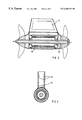
- FIG. 2 shows a sectional view of a propulsion pod cooled in accordance with the present invention.
- FIG. 3 shows a sectional view of a cooling surface arrangement in accordance with FIG. 2 .
- FIG. 4 shows sectional view of a cooling ducts, through which water flows, at the transition between the propulsion pod and the access shaft.
- FIG. 5 shows a sectional view of the arrangement of an inner double wall in the lower part of the access shaft
- FIG. 6 shows a detailed section through one end of the propulsion pod with heat bridges in the region of the coil winding heads.
- FIG. 1 which shows the prior art on which the invention is based
- 1 designates the electric propulsion motor
- 2 designates the propeller driven by the propulsion motor 1
- 3 designates the pod outer wall, whose contour is also retained in the part directed into the access shaft
- 4 designates the flange transition between the propulsion pod and the lower part of the access shaft
- 5 designates a flange in the middle of the access shaft.
- the cable harness 6 passes down through the access shaft to supply current to the electric motor 1 .
- a ladder 7 by means of which an inspector 8 has easy access to the lower part of the access shaft, is located in the access shaft itself. Because the propulsion pod is maintenance-free and is not configured to be accessible, the inspector 8 only has to monitor the flange connections 4 and 5 .
- the lower part of the ladder 7 is dispensed with in more recent embodiments, and therefore also in the case of the embodiment according to the invention.
- the lower part of the access shaft is therefore free for installation features, even for installation features which make access to the outer wall of the electric motor impossible.
- Auxiliary equipment for example bilge pumps, the compressed air supply for the seal at the transition of the access shaft to the ship etc., are fitted in the upper part of the access shaft.
- FIG. 2 shows a diagrammatic representation of a propulsion pod with the electric motor 10 , which is connected by heat ducts (not represented) to one or a number of cooling elements 11 in the lower part of the access shaft, in particular on the walls of the lower part of the access shaft.
- the propulsion pod shown has a hollow shaft through which water flows.
- the flow duct in the hollow shaft is designated by 12 and the arrows indicate the direction in which the water flows through the shaft.
- the heat ducts (not shown) are, like the flow duct, advantageously configured without installation features.
- FIG. 3 shows, again diagrammatically, cooling elements 13 and 14 located in the lower part of the access shaft.
- cooling elements 13 and 14 located in the lower part of the access shaft.
- all the cooling elements known from cooling technology can be employed here.
- the arrangement of the cooling elements is arbitrary and additional cooling elements are also possible in the free space of the hollow access shaft.
- the electric motor does not, in fact, need to be accessible.
- Coolant tubes 15 at the transition from the access shaft 16 to the propulsion pod 17 are shown in FIG. 4 . Like the hollow shaft shown in FIG. 2, flow takes place through them in the longitudinal direction.
- the outer surfaces of the coolant tubes 15 can also be connected to the inside of the propulsion motor by means of heat ducts.
- the coolant tubes 15 can, however, also be used for particularly intensive cooling of the part of the pod outer wall facing them.
- FIG. 5 shows a double-walled embodiment of the lower part of the access shaft with the outer wall 18 and an inserted inner wall 19 , with heat ducts 20 , which are here configured in an embodiment in which water flows through them, entering into the intermediate space between the outer wall 18 and the inner part 19 .
- the flow cross section for the coolant is preferably round; if heat ducts for air are used, inlet flow slots are preferably provided.
- FIG. 6 which shows a detailed section through one end of the body of the propulsion pod, 21 designates a heat bridge for the coil winding heads 22 of the stator windings 24 .
- the stator windings 24 are located centrally in the actual pod body 23 , which is preferably made from the same material as the propeller 29 , i.e. from propeller bronze.
- the air gap 30 is located between the rotor winding 25 and the stator winding 24 .
- the rotor 25 is arranged on an inner tube 26 , which is in turn fastened to the shaft 27 .
- the fastening takes place by means of a coupling 31 .
- the pod housing 23 also has cooling chambers 28 , which can be used as the outlet for heat ducts into the access shaft. In this case, it is then possible to dispense with enlarging the surface by ribs or the like.
- the coupling, the shaft bearing system etc. are not part of the invention and are therefore not shown in any more detail.
- a hollow space 33 which, if appropriate, is connected to the central part of the propulsion pod, which is subject to heat, by a large central bore 32 (shown by interrupted lines) in the shaft 27 . This permits good thermal utilization of the cool ends of the propulsion pod.
- the invention's cooling elements in accordance with the invention permit a multiplicity of cooling combinations.
- the individual measures are selected to suit the area in which the ship is traveling and the size of the motor.
- a common feature is that they dispense with long coolant paths and coolant circulating units. This results in a substantial improvement even when compared with the prior art shown in U.S. Pat. No. 5,403,216 and U.S. Pat. No. 2,714,866.
Landscapes
- Engineering & Computer Science (AREA)
- Chemical & Material Sciences (AREA)
- Combustion & Propulsion (AREA)
- Mechanical Engineering (AREA)
- Ocean & Marine Engineering (AREA)
- Power Engineering (AREA)
- Motor Or Generator Cooling System (AREA)
- Toys (AREA)
- Steering-Linkage Mechanisms And Four-Wheel Steering (AREA)
- Control Of Electric Motors In General (AREA)
- Motor Or Generator Frames (AREA)
- Structures Of Non-Positive Displacement Pumps (AREA)
- Automatic Cycles, And Cycles In General (AREA)
- Prevention Of Electric Corrosion (AREA)
Abstract
Description
Claims (21)
Applications Claiming Priority (5)
| Application Number | Priority Date | Filing Date | Title |
|---|---|---|---|
| DE19731816 | 1997-07-21 | ||
| DE19731816 | 1997-07-21 | ||
| DE1998101448 DE19801448C2 (en) | 1998-01-16 | 1998-01-16 | Electric propulsion system for ships |
| DE19801448 | 1998-01-16 | ||
| PCT/DE1998/002049 WO1999005023A1 (en) | 1997-07-21 | 1998-07-21 | Electric motor pod drive system for a vessel with a cooling device |
Publications (1)
| Publication Number | Publication Date |
|---|---|
| US6485339B1 true US6485339B1 (en) | 2002-11-26 |
Family
ID=26038541
Family Applications (1)
| Application Number | Title | Priority Date | Filing Date |
|---|---|---|---|
| US09/463,269 Expired - Lifetime US6485339B1 (en) | 1997-07-21 | 1998-07-21 | Electric motor pod drive system for a vessel with a cooling device |
Country Status (13)
| Country | Link |
|---|---|
| US (1) | US6485339B1 (en) |
| EP (1) | EP0998407B1 (en) |
| JP (1) | JP2001516663A (en) |
| CN (1) | CN1106318C (en) |
| AT (1) | ATE225278T1 (en) |
| AU (1) | AU744424B2 (en) |
| CA (1) | CA2297047C (en) |
| DK (1) | DK0998407T3 (en) |
| ES (1) | ES2185215T3 (en) |
| NO (1) | NO20000334D0 (en) |
| PT (1) | PT998407E (en) |
| RU (1) | RU2205129C2 (en) |
| WO (1) | WO1999005023A1 (en) |
Cited By (23)
| Publication number | Priority date | Publication date | Assignee | Title |
|---|---|---|---|---|
| US6685516B2 (en) * | 2001-06-29 | 2004-02-03 | Mitsubishi Heavy Industries, Ltd. | Azimuth propeller device |
| US20040214484A1 (en) * | 2001-06-14 | 2004-10-28 | Jari Ylitalo | Ship's propulsion arrangement and method |
| WO2004101356A1 (en) | 2003-05-16 | 2004-11-25 | Siemens Aktiengesellschaft | Ship propulsion system comprising cooling devices for the stator and rotor of the synchronous machine thereof |
| US20040248479A1 (en) * | 2001-08-30 | 2004-12-09 | Peter Hein | Electrical drive device for a ship with elastically supported electric motor |
| US20050009418A1 (en) * | 2001-11-29 | 2005-01-13 | Gunter Ries | Boat propulsion system |
| US20050042944A1 (en) * | 2001-08-30 | 2005-02-24 | Karsten Brach | Shock-proof electric marine engine, e.g. engine or generator |
| NL1032859C2 (en) * | 2006-11-13 | 2008-05-14 | Willdo B V | Vessel has component for forward movement and steering which is pivotable in relation to vessel and is impelled by primary drive. Steering component and forward impulsion unit are pivotable around common axis |
| US7841290B1 (en) | 2006-02-14 | 2010-11-30 | The United States Of America As Represented By The Secretary Of The Navy | Marine shaftless external propulsor |
| CN101938183A (en) * | 2010-09-30 | 2011-01-05 | 南阳防爆集团股份有限公司 | Mining type flameproof submersible motor |
| US20110165802A1 (en) * | 2008-09-08 | 2011-07-07 | Siemens Aktiengesellschaft | Vessel propulsion system for watercraft |
| EP2824027A1 (en) | 2013-07-09 | 2015-01-14 | ABB Oy | Ship's propulsion unit |
| EP2824806A1 (en) | 2013-07-09 | 2015-01-14 | ABB Oy | Ship's propulsion unit |
| US20150015105A1 (en) * | 2013-07-09 | 2015-01-15 | Abb Oy | Ship's propulsion unit |
| US20160288901A1 (en) * | 2015-03-31 | 2016-10-06 | Vantage Robotics, Llc | Propeller-motor assembly for efficient thermal dissipation |
| JP2017516710A (en) * | 2014-06-03 | 2017-06-22 | ロールス−ロイス アクチボラグRolls−Royce Aktiebolag | Pod propulsion device and method for cooling the same |
| CN107074338A (en) * | 2014-05-30 | 2017-08-18 | Abb瑞士股份有限公司 | Ship's pod propulsion unit |
| WO2018059844A1 (en) * | 2016-09-29 | 2018-04-05 | Siemens Aktiengesellschaft | Cooling of a pod drive |
| US20200017183A1 (en) * | 2018-07-16 | 2020-01-16 | Changzhou Golden Motor Technology Co Ltd. | Direct-drive electric outboard engine and outboard engine system |
| US11031836B2 (en) * | 2017-08-29 | 2021-06-08 | Siemens Aktiengeselldchaft | Stator for an electrical rotating machine |
| CN114275136A (en) * | 2021-12-30 | 2022-04-05 | 深圳市好盈科技有限公司 | Underwater propeller |
| US11342824B2 (en) | 2017-06-27 | 2022-05-24 | Bayerische Motoren Werke Aktiengesellschaft | Method for producing a rotor for an electrical machine, in particular of a motor vehicle, and rotor and motor vehicle |
| US20220169351A1 (en) * | 2020-12-01 | 2022-06-02 | City University Of Hong Kong | Hetero-stiffness robotic device |
| US12459624B1 (en) | 2023-04-20 | 2025-11-04 | Brunswick Corporation | Marine drives having an electric motor assembly and methods for making the same |
Families Citing this family (24)
| Publication number | Priority date | Publication date | Assignee | Title |
|---|---|---|---|---|
| EP0996567B1 (en) * | 1997-07-21 | 2001-11-14 | Siemens Aktiengesellschaft | Electromotive gondola or ship drive system with cooling device |
| DE19902837C1 (en) * | 1999-01-20 | 2000-08-10 | Siemens Ag | Rotating electrical machine with permanently excited rotor |
| EP1208632A2 (en) * | 1999-08-03 | 2002-05-29 | Siemens Aktiengesellschaft | Demagnetization-protected permanent magnet ship propulsion system |
| DE29923515U1 (en) | 1999-08-03 | 2000-12-14 | Siemens AG, 80333 München | Demagnetization-proof, permanently excited ship propulsion |
| FI115042B (en) | 2000-01-28 | 2005-02-28 | Abb Oy | Engine unit for ships |
| FR2815485B1 (en) | 2000-10-12 | 2003-01-24 | France Etat Armement | DEVICE FOR REDUCING NOISE AND ABSORBING VIBRATIONS GENERATED BY AN ELECTRIC MOTOR INTEGRATED IN A PROPULSION BOAT OF A VESSEL |
| DE102007021720B4 (en) | 2007-05-09 | 2014-01-23 | Siemens Aktiengesellschaft | Compressor system for underwater use in the offshore sector |
| DE102009026195B4 (en) * | 2009-07-17 | 2015-10-01 | Michael Heyde | Wind power generator with external rotor and internal cooling |
| DE102013214082A1 (en) * | 2013-07-18 | 2015-01-22 | Siemens Aktiengesellschaft | Electric nacelle drive for a ship |
| DE102013214087A1 (en) * | 2013-07-18 | 2015-01-22 | Siemens Aktiengesellschaft | Electric nacelle drive for a ship |
| EP3020625A1 (en) * | 2014-11-13 | 2016-05-18 | Siemens Aktiengesellschaft | Electric nacelle drive |
| RU2583125C1 (en) * | 2014-12-04 | 2016-05-10 | Общество с ограниченной ответственностью "Научно-производственный центр "Судовые электротехнические системы" (ООО "НПЦ "СЭС") | Marine propulsion installation |
| EP3069985A1 (en) * | 2015-03-20 | 2016-09-21 | ABB Oy | A vessel with a hull and a propulsion unit |
| CN105460194A (en) * | 2015-12-31 | 2016-04-06 | 武汉船用机械有限责任公司 | Pod propulsion device for ship |
| CN107804447A (en) * | 2017-12-01 | 2018-03-16 | 广东杰鹏游艇产业发展有限公司 | A kind of motor for applying to yacht promotes and control system |
| CN109436268A (en) * | 2018-09-26 | 2019-03-08 | 湖北环电磁装备工程技术有限公司 | Ship podded propeller |
| CN112520000A (en) * | 2019-09-17 | 2021-03-19 | 西门子(中国)有限公司 | Pod type propeller and ship |
| CN111674535B (en) * | 2020-06-24 | 2021-04-30 | 江苏科技大学 | Nacelle propeller suction type resistance suppression and auxiliary heat dissipation device |
| CN112455643A (en) * | 2020-12-07 | 2021-03-09 | 浙江海洋大学 | Novel refrigeration equipment for ship |
| US20240178723A1 (en) * | 2021-03-23 | 2024-05-30 | Lilium Eaircraft Gmbh | Cooling for an electric drive of an aircraft |
| EP3998696A1 (en) * | 2021-03-23 | 2022-05-18 | Lilium eAircraft GmbH | Cooling for an electric drive of an aircraft |
| CN114194403B (en) * | 2022-01-25 | 2023-06-02 | 广东汇天航空航天科技有限公司 | Heat radiation structure of driving device and aircraft |
| CN117040193A (en) * | 2023-08-14 | 2023-11-10 | 中国船舶集团有限公司第七〇四研究所 | A high-power submersible permanent magnet motor using multi-media cooling |
| CN117767664B (en) * | 2024-01-03 | 2025-10-24 | 武汉船用电力推进装置研究所(中国船舶集团有限公司第七一二研究所) | A cooling structure for pod propulsion motor |
Citations (17)
| Publication number | Priority date | Publication date | Assignee | Title |
|---|---|---|---|---|
| DE683970C (en) | 1936-12-01 | 1939-11-20 | Arno Fischer | Arrangement to compensate the thermal stresses of the stands of electrical machines which are inserted into the housing of a turbine or pump unit |
| US2714866A (en) * | 1951-02-19 | 1955-08-09 | Friedrich W Pleuger | Device for propelling a ship |
| DE1638276A1 (en) | 1967-03-24 | 1971-07-01 | Alsthom Cgee | Cooling system for encapsulated electrical machines |
| US3593050A (en) * | 1969-04-01 | 1971-07-13 | Ambac Ind | Trolling motor |
| US3650310A (en) * | 1970-07-16 | 1972-03-21 | Stewart & Stevenson Serv Inc | Combination boat trim tab and heat exchanger |
| US3791331A (en) * | 1972-05-05 | 1974-02-12 | E Dilley | Electric outboard motor |
| US3814961A (en) * | 1972-08-02 | 1974-06-04 | Ambac Ind | Trolling motor structure |
| US3841396A (en) * | 1973-06-12 | 1974-10-15 | T Knaebel | Finned heat exchanger and system |
| US4445046A (en) | 1981-06-30 | 1984-04-24 | Alsthom-Atlantique | High power immersed turbo-generator set having a gear box and external cooling |
| US5078628A (en) * | 1989-06-23 | 1992-01-07 | Newport News Shipbuilding And Dry Dock Company | Marine propulsor |
| US5101128A (en) | 1990-08-23 | 1992-03-31 | Westinghouse Electric Corp. | System and method for cooling a submersible electric propulsor |
| US5205653A (en) * | 1991-05-01 | 1993-04-27 | Westinghouse Electric Corp. | Bearing assembly and submersible propulsor unit incorporating the same |
| EP0581966A1 (en) | 1992-02-21 | 1994-02-09 | Fanuc Ltd. | Motor equipped with stator cooling means |
| US5403216A (en) | 1992-09-28 | 1995-04-04 | Kvaerner Masa-Yards Oy | Ship propulsion arrangement |
| US5445545A (en) * | 1994-10-11 | 1995-08-29 | Draper; Randal K. | Shrouded electric outboard motor |
| WO1997009771A1 (en) | 1995-09-05 | 1997-03-13 | Abb Kraft A/S | Arrangement in a bulb generator |
| US5698917A (en) * | 1995-09-25 | 1997-12-16 | Glacier Rpb Inc. | Electromagnetic bearing with a stationary armature canning arrangement |
Family Cites Families (2)
| Publication number | Priority date | Publication date | Assignee | Title |
|---|---|---|---|---|
| DE581966C (en) * | 1931-01-21 | 1933-08-05 | Philips Nv | Method of manufacturing stacked capacitors |
| DE2259738B2 (en) * | 1972-12-04 | 1975-08-28 | Siemens Ag, 1000 Berlin Und 8000 Muenchen | Cooling device for electrical generators in underwater power plants |
-
1998
- 1998-07-21 JP JP2000504038A patent/JP2001516663A/en active Pending
- 1998-07-21 AU AU92528/98A patent/AU744424B2/en not_active Expired
- 1998-07-21 PT PT98945016T patent/PT998407E/en unknown
- 1998-07-21 CN CN98807448A patent/CN1106318C/en not_active Expired - Lifetime
- 1998-07-21 US US09/463,269 patent/US6485339B1/en not_active Expired - Lifetime
- 1998-07-21 WO PCT/DE1998/002049 patent/WO1999005023A1/en not_active Ceased
- 1998-07-21 CA CA002297047A patent/CA2297047C/en not_active Expired - Lifetime
- 1998-07-21 EP EP98945016A patent/EP0998407B1/en not_active Expired - Lifetime
- 1998-07-21 ES ES98945016T patent/ES2185215T3/en not_active Expired - Lifetime
- 1998-07-21 AT AT98945016T patent/ATE225278T1/en not_active IP Right Cessation
- 1998-07-21 DK DK98945016T patent/DK0998407T3/en active
- 1998-07-21 RU RU2000104011/28A patent/RU2205129C2/en active
-
2000
- 2000-01-21 NO NO20000334A patent/NO20000334D0/en unknown
Patent Citations (17)
| Publication number | Priority date | Publication date | Assignee | Title |
|---|---|---|---|---|
| DE683970C (en) | 1936-12-01 | 1939-11-20 | Arno Fischer | Arrangement to compensate the thermal stresses of the stands of electrical machines which are inserted into the housing of a turbine or pump unit |
| US2714866A (en) * | 1951-02-19 | 1955-08-09 | Friedrich W Pleuger | Device for propelling a ship |
| DE1638276A1 (en) | 1967-03-24 | 1971-07-01 | Alsthom Cgee | Cooling system for encapsulated electrical machines |
| US3593050A (en) * | 1969-04-01 | 1971-07-13 | Ambac Ind | Trolling motor |
| US3650310A (en) * | 1970-07-16 | 1972-03-21 | Stewart & Stevenson Serv Inc | Combination boat trim tab and heat exchanger |
| US3791331A (en) * | 1972-05-05 | 1974-02-12 | E Dilley | Electric outboard motor |
| US3814961A (en) * | 1972-08-02 | 1974-06-04 | Ambac Ind | Trolling motor structure |
| US3841396A (en) * | 1973-06-12 | 1974-10-15 | T Knaebel | Finned heat exchanger and system |
| US4445046A (en) | 1981-06-30 | 1984-04-24 | Alsthom-Atlantique | High power immersed turbo-generator set having a gear box and external cooling |
| US5078628A (en) * | 1989-06-23 | 1992-01-07 | Newport News Shipbuilding And Dry Dock Company | Marine propulsor |
| US5101128A (en) | 1990-08-23 | 1992-03-31 | Westinghouse Electric Corp. | System and method for cooling a submersible electric propulsor |
| US5205653A (en) * | 1991-05-01 | 1993-04-27 | Westinghouse Electric Corp. | Bearing assembly and submersible propulsor unit incorporating the same |
| EP0581966A1 (en) | 1992-02-21 | 1994-02-09 | Fanuc Ltd. | Motor equipped with stator cooling means |
| US5403216A (en) | 1992-09-28 | 1995-04-04 | Kvaerner Masa-Yards Oy | Ship propulsion arrangement |
| US5445545A (en) * | 1994-10-11 | 1995-08-29 | Draper; Randal K. | Shrouded electric outboard motor |
| WO1997009771A1 (en) | 1995-09-05 | 1997-03-13 | Abb Kraft A/S | Arrangement in a bulb generator |
| US5698917A (en) * | 1995-09-25 | 1997-12-16 | Glacier Rpb Inc. | Electromagnetic bearing with a stationary armature canning arrangement |
Non-Patent Citations (3)
| Title |
|---|
| Andersen et al, New Type of Permanent Field Machines for Diesel Electric Propulsion Systems, AES 97-Civil or Military All Electric Ship-Int'l Symposium and Exhibition, XP002087162, pp. 4-14 (1997. |
| Gloel et al, Ein neues hocheffizientes Antriebssystem, Engineering, Schiff & Hafen, pp. 40-44 (1997) |
| Siemens Brochure, Siemens-Schottel-Propulsor (SSP) The Podded Electric Drive with Permanently Excited Motor (1997). |
Cited By (37)
| Publication number | Priority date | Publication date | Assignee | Title |
|---|---|---|---|---|
| US20040214484A1 (en) * | 2001-06-14 | 2004-10-28 | Jari Ylitalo | Ship's propulsion arrangement and method |
| US7189126B2 (en) * | 2001-06-14 | 2007-03-13 | Abb Oy | Ship's propulsion arrangement and method |
| US6685516B2 (en) * | 2001-06-29 | 2004-02-03 | Mitsubishi Heavy Industries, Ltd. | Azimuth propeller device |
| US7029339B2 (en) * | 2001-08-30 | 2006-04-18 | Siemens Aktiengesellschaft | Shock-proof electric marine engine, e.g. engine or generator |
| US20040248479A1 (en) * | 2001-08-30 | 2004-12-09 | Peter Hein | Electrical drive device for a ship with elastically supported electric motor |
| US20050042944A1 (en) * | 2001-08-30 | 2005-02-24 | Karsten Brach | Shock-proof electric marine engine, e.g. engine or generator |
| US20060105642A1 (en) * | 2001-11-29 | 2006-05-18 | Gunter Ries | Boat propulsion system |
| US7018249B2 (en) * | 2001-11-29 | 2006-03-28 | Siemens Aktiengesellschaft | Boat propulsion system |
| US20050009418A1 (en) * | 2001-11-29 | 2005-01-13 | Gunter Ries | Boat propulsion system |
| WO2004101356A1 (en) | 2003-05-16 | 2004-11-25 | Siemens Aktiengesellschaft | Ship propulsion system comprising cooling devices for the stator and rotor of the synchronous machine thereof |
| US20070117478A1 (en) * | 2003-05-16 | 2007-05-24 | Siemens Aktiengesellschaft | Ship propulsion system with cooling systems for the stator and rotor of the synchronous machine of the propulsion system |
| US7448929B2 (en) * | 2003-05-16 | 2008-11-11 | Siemens Aktiengesellschaft | Ship propulsion system with cooling systems for the stator and rotor of the synchronous machine of the propulsion system |
| US7841290B1 (en) | 2006-02-14 | 2010-11-30 | The United States Of America As Represented By The Secretary Of The Navy | Marine shaftless external propulsor |
| NL1032859C2 (en) * | 2006-11-13 | 2008-05-14 | Willdo B V | Vessel has component for forward movement and steering which is pivotable in relation to vessel and is impelled by primary drive. Steering component and forward impulsion unit are pivotable around common axis |
| US20110165802A1 (en) * | 2008-09-08 | 2011-07-07 | Siemens Aktiengesellschaft | Vessel propulsion system for watercraft |
| US8517785B2 (en) | 2008-09-08 | 2013-08-27 | Siemens Aktiengesellschaft | Vessel propulsion system for watercraft |
| CN101938183A (en) * | 2010-09-30 | 2011-01-05 | 南阳防爆集团股份有限公司 | Mining type flameproof submersible motor |
| EP2824806A1 (en) | 2013-07-09 | 2015-01-14 | ABB Oy | Ship's propulsion unit |
| EP2824027A1 (en) | 2013-07-09 | 2015-01-14 | ABB Oy | Ship's propulsion unit |
| US20150015105A1 (en) * | 2013-07-09 | 2015-01-15 | Abb Oy | Ship's propulsion unit |
| US9663210B2 (en) * | 2013-07-09 | 2017-05-30 | Abb Oy | Ship's propulsion unit |
| CN107074338A (en) * | 2014-05-30 | 2017-08-18 | Abb瑞士股份有限公司 | Ship's pod propulsion unit |
| JP2017516710A (en) * | 2014-06-03 | 2017-06-22 | ロールス−ロイス アクチボラグRolls−Royce Aktiebolag | Pod propulsion device and method for cooling the same |
| US9902478B2 (en) | 2014-06-03 | 2018-02-27 | Rolls-Royce Aktiebolag | Pod propulsion device and a method for cooling such |
| US11383808B2 (en) | 2014-06-03 | 2022-07-12 | Kongsberg Maritime Sweden Ab | Pod propulsion device and a method for cooling such |
| US20160288901A1 (en) * | 2015-03-31 | 2016-10-06 | Vantage Robotics, Llc | Propeller-motor assembly for efficient thermal dissipation |
| US10669008B2 (en) * | 2015-03-31 | 2020-06-02 | Vantage Robotics, Llc | Propeller-motor assembly for efficient thermal dissipation |
| WO2018059844A1 (en) * | 2016-09-29 | 2018-04-05 | Siemens Aktiengesellschaft | Cooling of a pod drive |
| US11342824B2 (en) | 2017-06-27 | 2022-05-24 | Bayerische Motoren Werke Aktiengesellschaft | Method for producing a rotor for an electrical machine, in particular of a motor vehicle, and rotor and motor vehicle |
| US11031836B2 (en) * | 2017-08-29 | 2021-06-08 | Siemens Aktiengeselldchaft | Stator for an electrical rotating machine |
| US10940928B2 (en) * | 2018-07-16 | 2021-03-09 | Changzhou Golden Motor Technology Co Ltd. | Direct-drive electric outboard engine and outboard engine system |
| EP3598614A1 (en) * | 2018-07-16 | 2020-01-22 | Changzhou Golden Motor Technology Co., Ltd | Direct-drive electric outboard engine and outboard engine system |
| US20200017183A1 (en) * | 2018-07-16 | 2020-01-16 | Changzhou Golden Motor Technology Co Ltd. | Direct-drive electric outboard engine and outboard engine system |
| US20220169351A1 (en) * | 2020-12-01 | 2022-06-02 | City University Of Hong Kong | Hetero-stiffness robotic device |
| US11685491B2 (en) * | 2020-12-01 | 2023-06-27 | City University Of Hong Kong | Hetero-stiffness robotic device |
| CN114275136A (en) * | 2021-12-30 | 2022-04-05 | 深圳市好盈科技有限公司 | Underwater propeller |
| US12459624B1 (en) | 2023-04-20 | 2025-11-04 | Brunswick Corporation | Marine drives having an electric motor assembly and methods for making the same |
Also Published As
| Publication number | Publication date |
|---|---|
| EP0998407B1 (en) | 2002-10-02 |
| ES2185215T3 (en) | 2003-04-16 |
| RU2205129C2 (en) | 2003-05-27 |
| CN1265074A (en) | 2000-08-30 |
| AU744424B2 (en) | 2002-02-21 |
| DK0998407T3 (en) | 2003-02-10 |
| CA2297047C (en) | 2004-01-27 |
| ATE225278T1 (en) | 2002-10-15 |
| AU9252898A (en) | 1999-02-16 |
| CA2297047A1 (en) | 1999-02-04 |
| PT998407E (en) | 2003-02-28 |
| NO20000334L (en) | 2000-01-21 |
| JP2001516663A (en) | 2001-10-02 |
| NO20000334D0 (en) | 2000-01-21 |
| EP0998407A1 (en) | 2000-05-10 |
| WO1999005023A1 (en) | 1999-02-04 |
| CN1106318C (en) | 2003-04-23 |
Similar Documents
| Publication | Publication Date | Title |
|---|---|---|
| US6485339B1 (en) | Electric motor pod drive system for a vessel with a cooling device | |
| KR100430321B1 (en) | Electric motor pod drive system for a vessel with a cooling device | |
| EP2824806B1 (en) | Ship's propulsion unit | |
| US6994602B2 (en) | Ship propulsion system | |
| US7061148B2 (en) | Device for cooling an electrical machine, in particular a synchronous electrical machine having permanent magnets | |
| JP6483158B2 (en) | Ship pod propulsion unit | |
| CN105431349B (en) | Electronic gondola driver for ship | |
| US7448929B2 (en) | Ship propulsion system with cooling systems for the stator and rotor of the synchronous machine of the propulsion system | |
| EP1415382B1 (en) | Electric propulsion units | |
| EP1010614B1 (en) | Propulsion and steering module for naval craft | |
| KR20160031538A (en) | Electric pod drive for a ship | |
| US6312298B1 (en) | Electromotive drive system for a ship | |
| US20150017032A1 (en) | Ship's propulsion unit | |
| US11345456B2 (en) | Cooling system for a water-borne vessel | |
| JP2002362487A (en) | Electric pod type thruster | |
| CN116101471A (en) | Offshore drive unit including closed cooling circuit | |
| CN112789217A (en) | Propulsion device for a ship and method for operating a propulsion device | |
| CN109301973B (en) | Electric motors and marine propulsion | |
| CN117767664A (en) | A pod propulsion motor cooling structure |
Legal Events
| Date | Code | Title | Description |
|---|---|---|---|
| AS | Assignment |
Owner name: SIEMENS AKTIENGESELLSCHAFT, GERMANY Free format text: ASSIGNMENT OF ASSIGNORS INTEREST;ASSIGNORS:HARTIG, RAINER;HEER, MANFRED;RZADKI, WOLFGANG;AND OTHERS;REEL/FRAME:011755/0494;SIGNING DATES FROM 20000329 TO 20000501 Owner name: SCHOTTEL GMBH +CO. KG., GERMANY Free format text: ASSIGNMENT OF ASSIGNORS INTEREST;ASSIGNORS:HARTIG, RAINER;HEER, MANFRED;RZADKI, WOLFGANG;AND OTHERS;REEL/FRAME:011755/0494;SIGNING DATES FROM 20000329 TO 20000501 |
|
| STCF | Information on status: patent grant |
Free format text: PATENTED CASE |
|
| FPAY | Fee payment |
Year of fee payment: 4 |
|
| FEPP | Fee payment procedure |
Free format text: PAYOR NUMBER ASSIGNED (ORIGINAL EVENT CODE: ASPN); ENTITY STATUS OF PATENT OWNER: LARGE ENTITY |
|
| FPAY | Fee payment |
Year of fee payment: 8 |
|
| AS | Assignment |
Owner name: SCHOTTEL GMBH, GERMANY Free format text: CHANGE OF NAME;ASSIGNOR:SCHOTTEL GMBH & CO., KG;REEL/FRAME:030070/0883 Effective date: 20070629 Owner name: SIEMENS AKTIENGESELLSCHAFT, GERMANY Free format text: ASSIGNMENT OF ASSIGNORS INTEREST;ASSIGNOR:SCHOTTEL GMBH;REEL/FRAME:030071/0189 Effective date: 20130115 |
|
| FPAY | Fee payment |
Year of fee payment: 12 |