US6472808B1 - Color cathode ray tube having electrostatic quadrupole lenses - Google Patents
Color cathode ray tube having electrostatic quadrupole lenses Download PDFInfo
- Publication number
- US6472808B1 US6472808B1 US09/468,861 US46886199A US6472808B1 US 6472808 B1 US6472808 B1 US 6472808B1 US 46886199 A US46886199 A US 46886199A US 6472808 B1 US6472808 B1 US 6472808B1
- Authority
- US
- United States
- Prior art keywords
- electrode
- electron beams
- focus voltage
- electron
- increasingly
- Prior art date
- Legal status (The legal status is an assumption and is not a legal conclusion. Google has not performed a legal analysis and makes no representation as to the accuracy of the status listed.)
- Expired - Fee Related
Links
Images


Classifications
-
- H—ELECTRICITY
- H01—ELECTRIC ELEMENTS
- H01J—ELECTRIC DISCHARGE TUBES OR DISCHARGE LAMPS
- H01J29/00—Details of cathode-ray tubes or of electron-beam tubes of the types covered by group H01J31/00
- H01J29/46—Arrangements of electrodes and associated parts for generating or controlling the ray or beam, e.g. electron-optical arrangement
- H01J29/58—Arrangements for focusing or reflecting ray or beam
-
- H—ELECTRICITY
- H01—ELECTRIC ELEMENTS
- H01J—ELECTRIC DISCHARGE TUBES OR DISCHARGE LAMPS
- H01J29/00—Details of cathode-ray tubes or of electron-beam tubes of the types covered by group H01J31/00
- H01J29/46—Arrangements of electrodes and associated parts for generating or controlling the ray or beam, e.g. electron-optical arrangement
- H01J29/48—Electron guns
- H01J29/50—Electron guns two or more guns in a single vacuum space, e.g. for plural-ray tube
- H01J29/503—Three or more guns, the axes of which lay in a common plane
-
- H—ELECTRICITY
- H01—ELECTRIC ELEMENTS
- H01J—ELECTRIC DISCHARGE TUBES OR DISCHARGE LAMPS
- H01J2229/00—Details of cathode ray tubes or electron beam tubes
- H01J2229/48—Electron guns
- H01J2229/4834—Electrical arrangements coupled to electrodes, e.g. potentials
- H01J2229/4837—Electrical arrangements coupled to electrodes, e.g. potentials characterised by the potentials applied
- H01J2229/4841—Dynamic potentials
Definitions
- the present invention relates to a cathode ray tube, and in particular to a color cathode ray tube having an electron gun employing a multistage focus lens for focusing a plurality of electron beams on a phosphor screen.
- Shadow mask type color cathode ray tubes are prevailingly used as TV picture tubes and monitor tubes for information terminals.
- the shadow mask type color cathode ray tubes house an electron gun for emitting a plurality (usually three) of electron beams at one end of an evacuated envelope, a phosphor screen formed of phosphors coated on an inner surface of the evacuated envelope at the other end thereof for emitting light of a plurality (usually three) of colors, and a shadow mask which serves as a color selection electrode and is closely spaced from the phosphor screen.
- the electron beams emitted from the electron gun are deflected to scan the phosphor screen two-dimensionally by magnetic fields generated by a deflection yoke mounted externally of the evacuated envelope and to display a desired image on the phosphor screen.
- FIG. 17 shows a cross-sectional view for explaining an example of the constitution of the shadow mask type color cathode ray tube
- reference numeral 201 denotes a panel portion forming a viewing screen
- 202 denotes a neck portion for housing an electron gun
- 203 denotes a funnel portion for connecting the panel portion and the neck portion
- 204 denotes a phosphor screen
- 205 denotes a shadow mask serving as a color selection electrode
- 206 denotes a mask frame for supporting the shadow mask 205
- 207 denotes a magnetic shield for shielding extraneous magnetic fields such as the earth's magnetic field
- 208 denotes a mask suspension mechanism
- 9 denotes an in-line type electron gun
- 10 denotes a deflection yoke
- 11 denotes an internal conductive coating
- 12 denote stem pins
- 13 denotes a getter.
- the evacuated envelope is comprised of the panel portion 201 , the neck portion 202 and the funnel portion 203 , and electron beams B (one center electron beam and two side electron beams) emitted from the electron gun 9 housed in the neck portion 202 scan the phosphor screen 204 in two dimensions by the horizontal and vertical direction magnetic fields produced by the deflection yoke 10 .
- the deflection yoke 10 is of a self-converging type which provides a pin cushion-like horizontal deflection magnetic field and a barrel-like vertical deflection magnetic field to converge a plurality of electron beams over the entire phosphor screen.
- the electron beams B are modulated in amount by modulating signals such as video signals supplied via the stem pins 12 , are color-selected by the shadow mask 205 disposed immediately in front of the phosphor screen 204 , and impinge upon the phosphors of the corresponding colors to reproduce a desired image.
- the cathode ray tubes of this kind are provided with a multistage focus lens in the electron gun and a dynamic focusing system is widely adopted where at least one of the electrodes constituting the multistage focus lens is supplied with a voltage varying dynamically, to obtain sufficiently small electron beam spots over the entire phosphor screen.
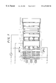
- FIG. 18 is a schematic cross-sectional view of an example of an electrode structure of an electron gun employed in a color cathode ray tube, taken perpendicular to the in-line direction of three in-line electron beams.
- reference numeral 1 denote three cathodes each having a heater incorporated therein
- electron beam generating means comprises the cathodes 1 , a first electrode 2 serving as a control electrode and a second electrode 3 serving as an accelerating electrode and the electron beam generating means forms electrons generated by the three cathodes 1 into three respective electron beams.
- Electron beam focusing means comprises a third electrode 4 , a fourth electrode 5 , a fifth electrode 6 and an anode 7 , and the electron beam focusing means accelerates the three electron beams and focuses them on the phosphor screen 204 .
- Reference numeral 8 denotes a shield cup and Eb is an anode voltage.
- the fifth electrode 6 is divided into a first member 61 and a second member 62 .
- the third electrode 4 , the fourth electrode 5 and the first member 61 of the fifth electrode 6 form a first-stage focusing lens, and the second member 62 of the fifth electrode 6 and the anode 7 form a second-stage focusing lens.
- the electrons emitted from the cathodes 1 heated by the heaters are accelerated toward the first electrode 2 serving as an electron beam control electrode by an accelerating potential of the second electrode 3 to form three electron beams.
- the three electron beams After passing through the electron beam apertures in the second electrode 3 and the third electrode 4 , the three electron beams are slightly focused by the first-stage focusing lens formed by the third electrode 4 , the fourth electrode 5 and the first member 61 of the fifth electrode 6 .
- the electron beams After passing through the first-stage focusing lens, the electron beams enter the second-stage focusing lens formed by the second member 62 of the fifth electrode 6 and the anode 7 and serving as a main lens.
- reference numeral 63 denotes a correction plate electrode disposed within the second member 62 of the fifth electrode 6 and 71 is a correction plate electrode disposed within the anode 7 .
- the three respective electron beams are focused while they pass through the second-stage focusing lens, then are subjected to color selection by the shadow mask 205 , and then are focused on phosphor elements of an intended color of the phosphor screen 204 to form an electron beam spot.
- a first focusing voltage Vf 1 of a fixed voltage is applied to the third electrode 4 and the first member 61 of the fifth electrode 6
- a second focusing voltage (Vf 2 +dVf) of a fixed voltage Vf 2 superposed with a dynamic voltage dVf varying in synchronism with deflection angle of the electron beams scanning the phosphor screen 204 is applied to the second member 62 of the fifth electrode 6 .
- an electrostatic quadrupole lens is formed by four vertical plates 611 attached to the end of the first member 61 of the fifth electrode 6 on the second member 62 side thereof and two horizontal plates 621 attached to the end of the second member 62 of the fifth electrode 6 on the first member 61 side thereof.
- electron guns for use in color cathode ray tubes such as TV picture tubes and display monitor tubes need to control the cross-sectional shape of the electron beams properly according to the amount of electron beam deflection so as to provide a good focus characteristic and high resolution over the entire viewing screen.
- the cross-sectional shape of the electron beams entering the main lens is elongated vertically according to the increasing deflection angle of the electron beams by the astigmatism-correcting electrostatic quadrupole lens, consequently the vertical diameter of the cross section of the electron beams is influenced greatly by the deflection defocusing which compresses the vertical diameter of the cross section of the electron beams and expands the horizontal diameter of the cross section to elongate the cross section horizontally, and as a result the electron beam spots are elongated horizontally at the periphery of the viewing screen and it was difficult to obtain good and uniform focus over the entire viewing screen.
- another electrostatic quadrupole lens serving as an electron beam shaping lens is formed by dividing the fifth electrode again or by dividing the third electrode again and is disposed in a position remoter from the anode than the above electrostatic quadrupole lens is.
- the additional electrostatic quadrupole lens diffuses the electron beams in the direction in which the anode-side electrostatic quadrupole lens focuses the electron beams and focuses the electron beams in the direction in which the anode-side electrostatic quadrupole lens diffuses the electron beams such that the additional electrostatic quadrupole lens has opposite effects on the electron beams from the anode-side electrostatic quadrupole lens.
- the electrostatic quadrupole lens for shaping the electron beams can be configured so as to elongate the cross section more horizontally according to the increase in the electron beam deflection and the astigmatism-correcting electrostatic quadrupole lens can shape the cross-sectional shape of the electron beams easily, and consequently good and uniform focus can be obtained over the entire viewing screen.
- a color cathode ray tube comprising an evacuated envelope comprising a panel portion, a neck portion and a funnel portion for connecting said panel portion and said neck portion, a phosphor screen formed on an inner surface of said panel portion, an in-line type electron gun housed in said neck portion, and an electron beam deflection yoke mounted around said neck portion, said in-line type electron gun comprising an electron beam generating section having a plurality of in-line cathodes, a first electrode serving as an electron beam control electrode and a second electrode serving as an accelerating electrode arranged in the order named for projecting a plurality of electron beams arranged approximately in parallel with each other in a horizontal plane toward said phosphor screen, an electron beam focusing section comprising a third electrode, a fourth electrode, a fifth electrode and an anode arranged in the order named for focusing said plurality of electron beams on said phosphor screen, said third electrode comprising a first electrode serving as an electron beam control electrode and a second electrode serving as an accelerating electrode
- a color cathode ray tube comprising an evacuated envelope comprising a panel portion, a neck portion and a funnel portion for connecting said panel portion and said neck portion, a phosphor screen formed on an inner surface of said panel portion, an in-line type electron gun housed in said neck portion, and an electron beam deflection yoke mounted around said neck portion, said in-line type electron gun comprising an electron beam generating section having three in-line cathodes, an electron beam control electrode and an accelerating electrode arranged in the order named for projecting three electron beams arranged approximately in parallel with each other in a horizontal plane toward said phosphor screen, an electron beam focusing section comprising a third electrode, a fourth electrode, a fifth electrode and an anode arranged in the order named for focusing the three electron beams on said phosphor screen, said third electrode comprising a first group of members and a second group of members of said third electrode, said fifth electrode comprising a
- FIG. 1 is a schematic cross-sectional view of an electron gun for explaining a color cathode ray tube in accordance with a first embodiment of the present invention
- FIGS. 2A and 2B are cross-sectional views of the electron gun taken at lines IIA—IIA and IIB—IIB of FIG. 1, respectively;
- FIGS. 3A and 3B are cross-sectional views of the electron gun taken at lines IIIA—IIIA and IIIB—IIIB of FIG. 1, respectively;
- FIG. 4 is a schematic enlarged cross-sectional view of a portion of the electron gun of FIG. 1;
- FIG. 5 is a graph showing the relationship between the electron beam astigmatism and the ratio L/D where D is a diameter of an electron beam aperture in the surface of the second member of the fourth electrode on the fourth-electrode side thereof and L is an axial distance measured from the surface of the second member on the fourth-electrode side thereof to the electron beam aperture in the surface of the second member on the first-member side thereof as indicated in FIG. 4;
- FIG. 6A is a plan view of a surface of a modification of the second member of the third electrode on the first member side thereof
- FIG. 6B is a plan view of the surface viewed through an aperture in a surface of the second member on the fourth electrode side thereof;
- FIG. 7 is a schematic cross-sectional view of an electron gun for explaining a color cathode ray tube in accordance with a second embodiment of the present invention.
- FIGS. 8A and 8B are cross-sectional views of the electron gun taken at lines VIIIA—VIIIA and VIIIB—VIIIB of FIG. 7, respectively, and FIG. 8C is a plan view of a modification of the second member of third electrode in FIG. 7;
- FIG. 9 is a schematic cross-sectional view of an electron gun for explaining a color cathode ray tube in accordance with a third embodiment of a color cathode ray tube according to the present invention.
- FIG. 10 is an illustration of waveforms of focus voltages
- FIGS. 11A to 11 C are illustrations of one type of an electrostatic quadrupole lens, FIG. 11A being a cross-sectional view of the electrostatic quadrupole lens of FIG. 11B taken along line 110 A— 110 A, FIG. 11B being a cross-sectional view of the electrostatic quadrupole lens of FIG. 11A taken along line 110 B— 110 B, and FIG. 11C being a cross-sectional view of the electrostatic quadrupole lens of FIG. 11A taken along line 110 C— 110 C;
- FIGS. 12A to 12 C are illustrations of another type of an electrostatic quadrupole lens, FIG. 12A being a cross-sectional view of the electrostatic quadrupole lens of FIG. 11B taken along line 120 A— 120 A, FIG. 12B being a cross-sectional view of the electrostatic quadrupole lens of FIG. 12A taken along line 120 B— 120 B, and FIG. 11C being a cross-sectional view of the electrostatic quadrupole lens of FIG. 12B taken along line 110 C— 110 C;
- FIGS. 13A to 13 C are illustrations of another type of an electrostatic quadrupole lens, FIG. 13A being a cross-sectional view of the electrostatic quadrupole lens of FIG. 13B taken along line 130 A— 130 A, FIG. 13B being a cross-sectional view of the electrostatic quadrupole lens of FIG. 13A taken along line 130 B— 130 B, and FIG. 13C being a cross-sectional view of the electrostatic quadrupole lens of FIG. 13B taken along line 130 C— 130 C;
- FIGS. 14A to 14 C are illustrations of another type of an electrostatic quadrupole lens, FIG. 14A being a cross-sectional view of the electrostatic quadrupole lens of FIG. 14B taken along line 140 A— 140 A, FIG. 14B being a cross-sectional view of the electrostatic quadrupole lens of FIG. 14 A taken along line 140 B— 140 B, and FIG. 14C being a cross-sectional view of the electrostatic quadrupole lens of FIG. 14A taken along line 140 C— 140 C;
- FIGS. 15A to 15 D are illustrations of another type of an electrostatic quadrupole lens, FIG. 15A being a cross-sectional view of the electrostatic quadrupole lens of FIG. 15C taken along line 150 A— 150 A, FIG. 15B being a cross-sectional view of the electrostatic quadrupole lens of FIG. 15A taken along line 150 B— 150 B, FIG. 15C being a cross-sectional view of the electrostatic quadrupole lens of FIG. 15A taken along line 150 C— 150 C and FIG. 15D being a cross-sectional view of the electrostatic quadrupole lens of FIG. 15A taken along line 150 D— 150 D;
- FIGS. 16A to 16 C are illustrations of one type of a main lens, FIG. 16A being a cross-sectional view of the main lens, and FIGS. 16B and 16C being plan views of the facing portions of electrodes constituting the main lens, respectively;
- FIG. 17 is across-sectional view of an example of a shadow mask type color cathode ray tube.
- FIG. 18 is a schematic cross-sectional view of an example of a prior art electron gun used in a color cathode ray tube.
- FIG. 1 is a schematic cross-sectional view of an electron gun viewed in a direction perpendicular to the in-line direction of the three in-line electron beams for explaining a first embodiment of a color cathode ray tube according to the present invention.
- the same reference numerals as utilized in FIG. 18 designate corresponding portions in FIG. 1 .
- electron beam generating means comprises cathodes 1 , a first electrode 2 serving as a control electrode and a second electrode 3 serving as an accelerating electrode, and electron beam focusing means comprises a first member 41 and a second member 42 of a third electrode 4 , a fourth electrode 5 , a first member 61 and a second member 62 of a fifth electrode 6 , an anode 7 and a shield cup 8 .
- the second electrode 3 and the fourth electrode 5 are supplied with a fixed voltage Ec 2 of 400 to 1000 V
- the first member 41 of the third electrode 4 and the first member 61 of the fifth electrode 6 are supplied with a first focus voltage of a fixed voltage Vf 1 .
- the second member 42 of the third electrode 4 and the second member 62 of the fifth electrode 6 are supplied with a second focus voltage (Vf 2 +dVf) of a fixed voltage Vf 2 superposed with a dynamic voltage dVf varying with a deflection angle of the electron beams scanning the viewing screen.
- An astigmatism-correcting electrostatic quadrupole lens is formed between the first member 61 and the second member 62 of the fifth electrode for elongating the cross section of the electron beams vertically increasingly with an increase in the dynamic voltage.
- This electrostatic quadrupole lens is comprised of four vertical plates 611 attached to the end of the first member 61 of the fifth electrode on the second member 62 side thereof and two horizontal plates 621 attached to the second member 62 of the fifth electrode on the first member 61 side thereof.
- FIGS. 2A and 2B are plan views of the first member 41 and the second member 42 of the third electrode 4 , respectively, FIG. 2A being an illustration of electron beam apertures 41 a formed in a surface of the first member 41 on the second member 42 side thereof and FIG. 2B being an illustration of electron beam apertures 42 a formed in a surface of the second member 42 on the first member 41 side thereof.
- three horizontally elongated electron beam apertures 41 a are formed in the surface of the first member 41 on the second member 42 side thereof, and as shown in FIG. 2B, three vertically elongated electron beam apertures 42 a are formed in the surface of the second member 42 on the first member 41 side thereof.
- an electron beam-shaping electrostatic quadrupole lens is formed between the first member 41 and the second member 42 of the third electrode 4 for elongating the cross section of the electron beams less vertically, that is, elongating the cross section of the electron beams more horizontally with an increase in the dynamic voltage.
- FIG. 3A is a plan view of the second member 42 of the third electrode 4 taken at line IIIA—IIIA of FIG. 1
- FIG. 3B is a plan view of the fourth electrode 5 taken at line IIIB—IIIB of FIG. 1 .
- the electron beam apertures 42 b formed in the surface of the second member 42 on the fourth electrode 5 side thereof are circular and are larger than the electron beam apertures 42 a formed in the surface of the second member 42 on the first member 41 side thereof such that edges of the electron beam apertures 42 a are viewed through the electron beam apertures 42 b .
- the electron beam apertures 5 a in the fourth electrode 5 are circular.
- FIG. 4 is an enlarged view of a portion of the electron gun of FIG. 1 .
- FIG. 5 shows the relationship between the electron beam astigmatism and the ratio L/D where D is a diameter of the electron beam aperture 42 b in the surface of the second member 42 of the third electrode 4 on the fourth-electrode 5 side thereof and L is an axial distance measured from the surface of the second member 42 on the fourth-electrode 5 side thereof to the electron beam aperture in the surface of the second member 42 on the first-member 41 side thereof as indicated in FIG. 4 .
- the voltage (Vf 2 +dVf) applied to the second member 42 of the third electrode and the voltage Ec 2 applied to the fourth electrode 5 have the relationship (Vf 2 +dVf)>Ec 2 at all times, and consequently an electrostatic quadrupole lens is formed between the second member 42 of the third electrode and the fourth electrode 5 such that a diverging lens is formed within the second member 42 by the vertically elongated apertures 42 a in the surface of the second member 42 on the first member 41 side and the electron beams experience diffusing forces stronger in the horizontal direction.
- the electron beams experience diffusing forces increasingly stronger in the horizontal direction as the dynamic voltage dVf is increased and their cross sections are more elongated horizontally, because the potential difference between the second member 42 of the third electrode and the fourth electrode 5 increases as the dynamic voltage dVf is increased.
- the electron lens formed between the second member 42 of the third electrode and the fourth electrode 5 elongates the cross section of the electron beams increasingly in the horizontal direction as the dynamic voltage dVf is increased like the electrostatic quadrupole lens formed between the first member 41 and the second member 42 of the third electrode, and this additional horizontal elongation of the cross section of the electron beams increases the amount of the beam shaping and provides a sufficient amount of shaping of the electron beams. Therefore the present embodiment provides good and uniform focus over the entire viewing screen.
- the electron beam apertures in the surface of the second member 42 of the third electrode 4 on the first member 41 side thereof may be made in the form of vertically elongated keyholes as shown in FIG. 6A, but the electron beam apertures in the fourth electrode is circular.
- FIG. 6B is a plan view of the modification of the second member 42 taken at line IIIA—IIIA of FIG. 1 .
- the electron lens formed between the second member 42 of the third electrode and the fourth electrode 5 elongates the cross section of the electron beams increasingly in the horizontal direction as the dynamic voltage dVf is increased and this additional horizontal elongation of the cross section of the electron beams increases the amount of the beam shaping and provides a sufficient amount of shaping of the electron beams. Therefore this modification provides good and uniform focus over the entire viewing screen.
- FIG. 7 is a schematic cross-sectional view of an electron gun viewed in a direction perpendicular to the in-line direction of the three in-line electron beams for explaining a second embodiment of a color cathode ray tube according to the present invention.
- the same reference numerals as utilized in FIG. 1 designate corresponding portions in FIG. 7 .
- the electron gun of this embodiment is similar to that of the previous embodiment, except that the second member 420 of the third electrode 4 is of a plate electrode type in this embodiment.
- FIG. 8A is a plan view of the second member 420 of the third electrode 4 taken at line VIIIA—VIIIA of FIG. 7, and FIG. 8B is a plan view of the fourth electrode 5 taken at line VIIIB—VIIIB of FIG. 1 .
- the electron beam apertures 420 a in the second member 420 of the third electrode 4 are vertically elongated and the apertures 5 a in the fourth electrode 5 is circular.
- the voltage (Vf 2 +dVf) applied to the second member 420 of the third electrode and the voltage Ec 2 applied to the fourth electrode 5 have the relationship (Vf 2 +dVf)>Ec 2 at all times, and consequently an electrostatic quadrupole lens is formed between the second member 420 of the third electrode and the fourth electrode 5 such that the electron beams experience diffusing forces caused by the vertically elongated apertures 420 a in the second member 420 and stronger in the horizontal direction.
- the electron beams experience diffusing forces increasingly stronger in the horizontal direction as the dynamic voltage dVf is increased and their cross sections are more elongated horizontally, because the potential difference between the second member 420 of the third electrode and the fourth electrode 5 increases as the dynamic voltage dVf is increased.
- the electron lens formed between the second member 420 of the third electrode and the fourth electrode 5 elongates the cross section of the electron beams increasingly in the horizontal direction as the dynamic voltage dVf is increased like the electrostatic quadrupole lens formed between the first member 41 and the second member 420 of the third electrode, and this additional horizontal elongation of the cross section of the electron beams increases the amount of the beam shaping and provides a sufficient amount of shaping of the electron beams. Therefore the present embodiment provides good and uniform focus over the entire viewing screen.
- the electron beam apertures 421 a in the second member 420 of the third electrode 4 may be made in the form of vertically elongated keyholes as shown in FIG. 8 C.
- FIG. 8C is a plan view of the modification of the second member 420 taken at line VIIIA—VIIIA of FIG. 7 .
- the electron lens formed between the second member 420 of the third electrode and the fourth electrode 5 elongates the cross section of the electron beams increasingly in the horizontal direction as the dynamic voltage dVf is increased and this additional horizontal elongation of the cross section of the electron beams increases the amount of the beam shaping and provides a sufficient amount of shaping of the electron beams. Therefore this modification also provides good and uniform focus over the entire viewing screen.
- FIG. 9 is a schematic cross-sectional view of an electron gun viewed in a direction perpendicular to the in-line direction of the three in-line electron beams for explaining a third embodiment of a color cathode ray tube according to the present invention.
- the same reference numerals as utilized in FIG. 1 designate corresponding portions in FIG. 9 .
- the present embodiment differs from the first and second embodiments in that the fifth electrode 6 are divided into a first member 61 , a second member 62 and a third member 64 and in that the first member 61 and the second member 62 are supplied with a second focus voltage (Vf 2 +dVf) of a fixed voltage Vf 2 superposed with a dynamic voltage dVf and the third member 64 is supplied with a fixed focus voltage Vf 1 .
- An electrostatic quadrupole lens is formed by two horizontal plates 611 attached to the end of the first member 61 on the third member 64 side thereof and four vertical plates 641 attached to the end of the third member 64 on the first member 61 side thereof.
- the electron beam apertures 41 a and 42 a in the third electrode 4 are similar to those in the third electrode 4 in FIGS. 2A and 2B, respectively, and a cross-sectional view of the third electrode 4 taken at line III—III of FIG. 9 is similar to that of FIG. 3 A.
- the second electrode 3 and the fourth electrode 5 are supplied with a fixed voltage Ec 2 of about 400 V to about 1000 V
- the first member 41 of the third electrode and the third member 64 of the fifth electrode are supplied with a first focus voltage Vf 1
- the second member 42 of the third electrode and the first member 61 and the second member 62 of the fifth electrode are supplied with a second focus voltage (Vf 2 +dVf) of a fixed voltage Vf 2 superposed with a dynamic an voltage dVf varying with deflection angle of the electron beams scanning the viewing screen.
- An astigmatism-correcting electrostatic quadrupole lens is formed between the first member 61 and the third member 64 of the fifth electrode for increasingly elongating the cross section of the electron beams vertically as the dynamic voltage dVf increases, and an electron lens is formed between the third member 64 and the second member 62 of the fifth electrode for decreasing the strength of focusing the electron beams in both the horizontal and vertical directions as the dynamic voltage dVf increases.
- three horizontally elongated electron beam apertures 41 a are formed in the surface of the first member 41 of the third electrode 4 on the second member 42 side thereof, and as shown in FIG. 2B, three vertically elongated electron beam apertures 42 a are formed in the surface of the second member 42 of the third electrode 4 on the first member 41 side thereof.
- An electron beam-shaping electrostatic quadrupole lens is formed between the first member 41 and the second member 42 of the third, electrode for increasingly elongating the cross section of the electron beams with an increase in the dynamic voltage dVf.
- the electron lens formed between the third member 64 and the second member 62 of the fifth electrode focuses the electron beams in both the horizontal and vertical directions.
- the dynamic voltage dVf increases, that is, as the deflection of the electron beams increases, the focusing strength of the electron lens formed between the third and second members 64 , 62 of the fifth electrode weakens due to the decrease in the potential difference between the third member 64 and the second member 62 , and consequently the curvature of the image field is corrected.
- another electron lens is formed between the third member 64 and the second member 62 of the fifth electrode for correcting the curvature of the image field, and consequently the lower dynamic voltage can provide good focus over the entire viewing screen than prior art cathode ray tubes.
- the electron lens formed between the second member 42 of the third electrode and the fourth electrode 5 serves to increasingly elongate the cross section of the electron beams horizontally with the increase in the dynamic voltage like the electrostatic quadrupole lens formed between the first member 41 and the second member 42 of the third electrode as in the first embodiment, such that the beam-shaping amount of horizontal elongation of the cross section of the electron beams is increased to provide a sufficient amount of the beam shaping and good and uniform focus is obtained over the entire viewing screen.
- FIG. 10 is an illustration of waveforms of the focus voltages to be used in the first to third embodiments.
- the fixed DC voltage Vf 1 is selected higher than the fixed DC voltage Vf 2 to satisfy the following relationship: the first focus voltage Vf 1 >the second focus voltage (Vf 2 +dVf).
- the electron beam apertures in the first electrode 2 are circles, squares, vertically or horizontally elongated ovals or ellipses, or vertically or horizontally elongated rectangles.
- the electron beam apertures in the second electrode 3 are circles, squares, or rectangles. Sometimes each aperture in the second electrode is superposed with a rectangular slit in a surface of the second electrode on a first- or third-electrode side thereof.
- the electron beam apertures in a surface of the first member 41 of the third electrode 4 on a second-electrode 3 side are circles, and those in a surface of the first member 41 on a second-member 42 side are horizontally elongated rectangles or horizontally elongated keyholes.
- the electron beam apertures in the fourth electrode 5 are circles.
- the electron beam apertures in a surface of the fifth electrode 6 on a fourth-electrode 5 side are circles.
- an quadrupole lens is formed by four vertical plates 101 attached to one electrode 300 of a pair of opposing electrodes 200 , 300 and two horizontal plates 102 attached to the other 200 of the opposing electrodes 200 , 300 to sandwich the four vertical plates 101 .
- FIG. 11A is a cross-sectional view taken at line 110 A— 110 A in FIG. 11B
- FIG. 11B is a cross-sectional view taken at line 110 B— 110 B in FIG. 1A
- FIG. 11C is a cross-sectional view taken at line 110 C— 110 C in FIG. 11 A.
- Reference numerals 200 a and 300 a denote circular apertures.
- FIGS. 12A to 12 C an quadrupole lens is formed by three vertically elongated rectangles 500 a formed in one electrode 500 of a pair of opposing electrodes 400 , 500 and three horizontally elongated rectangles 400 a formed in the other 400 of the opposing electrodes 400 , 500 .
- FIG. 12A is a plan view taken at line 120 A— 120 A in FIG. 12B
- FIG. 12B is a cross-sectional view taken at line 120 B— 120 B in FIG. 12A
- FIG. 12C is a plan view taken at line 120 C— 120 C in FIG. 12 B.
- FIGS. 13A to 13 C an quadrupole lens is formed by three vertically elongated keyholes 700 a formed in one electrode 700 of a pair of opposing electrodes 600 , 700 and three horizontally elongated keyholes 600 a formed in the other 600 of the opposing electrodes 600 , 700 .
- FIG. 13A is a plan view taken at line 130 A— 130 A in FIG. 12B
- FIG. 12B is a cross-sectional view taken at line 130 B— 130 B in FIG. 13A
- FIG. 13C is a plan view taken at line 130 C— 130 C in FIG. 13 B.
- an quadrupole lens is formed by three circular apertures 901 a formed in a plate electrode 901 disposed displaced from an end of one electrode 900 of a pair of opposing electrodes 800 , 900 inwardly into the electrode 900 and a pair of horizontal plates 801 sandwiching three electron beam paths, having their edges closely spaced from the three circular apertures 901 a and attached to the other 800 of the opposing electrodes 800 , 900 .
- FIG. 14A is a cross-sectional view taken at line 140 A— 140 A in FIG. 14B
- FIG. 14B is a cross-sectional view taken at line 140 B— 140 B in FIG. 14A
- FIG. 14C is a cross-sectional view taken at line 140 C— 140 C in FIG. 14 A.
- Reference numeral 800 a denote circular apertures and 900 a is a large-diameter single-opening.
- an quadrupole lens is formed by three vertically elongated rectangular apertures 1100 a formed in an end face of one electrode 1100 of a pair of opposing electrodes 1000 , 1100 and three pairs of horizontal plates 1001 each pair sandwiching a respective one of three electron beam paths, each pair extending into a respective one of the three rectangular apertures 1100 a and attached to the other 1000 of the opposing electrodes 1000 , 1100 .
- FIG. 15A is a cross-sectional view taken at line 150 A— 150 A in FIG. 15C
- FIG. 15B is a cross-sectional view taken at line 150 B— 150 B in FIG. 15A
- FIG. 15C is a cross-sectional view taken at line 150 C— 150 C in FIG. 15 A
- FIG. 15D is a cross-sectional view taken at line 150 D— 150 D in FIG. 15 A.
- Reference numeral 1100 a denote circular apertures.
- the second member 62 of the fifth electrode 6 and the anode 7 form a main lens, and they have single openings 62 a , 7 a in their respective opposing end faces, respectively, as shown in FIG. 16 A.
- the second member 62 and the anode 7 may be provided with a plate electrode 63 ( 71 ) having three circular apertures 63 a ( 71 a ) as shown in FIG. 16B, a plate electrode 63 ( 71 ) having three elliptical apertures 63 a ( 71 a ) as shown in FIG. 16C or a plate electrode 63 ( 71 ) having three polygonal apertures.
- an electron beam-shaping electrostatic quadrupole lens is formed between the first member 41 and the second member 42 of the third electrode, and an electron lens is formed between the electron beam apertures 42 a in the end face of the second member 42 on the first member 41 side thereof and the fourth electrode 5 adjacent to the second member 42 for diffusing the electron beams increasingly in the horizontal direction and for focusing the electron beams increasingly in the vertical direction with the increase in the difference between the voltage applied to the fourth electrode 5 and the second focus voltage applied to the second member 42 .
- the shaping strength of elongating the cross section of the electron beams horizontally can be increased to provide a sufficient amount of beam shaping such that a color cathode ray tube provides good and uniform focus over the entire viewing screen.
Landscapes
- Cathode-Ray Tubes And Fluorescent Screens For Display (AREA)
Applications Claiming Priority (2)
| Application Number | Priority Date | Filing Date | Title |
|---|---|---|---|
| JP10-365446 | 1998-12-22 | ||
| JP10365446A JP2000188068A (ja) | 1998-12-22 | 1998-12-22 | カラー陰極線管 |
Publications (1)
| Publication Number | Publication Date |
|---|---|
| US6472808B1 true US6472808B1 (en) | 2002-10-29 |
Family
ID=18484284
Family Applications (1)
| Application Number | Title | Priority Date | Filing Date |
|---|---|---|---|
| US09/468,861 Expired - Fee Related US6472808B1 (en) | 1998-12-22 | 1999-12-21 | Color cathode ray tube having electrostatic quadrupole lenses |
Country Status (6)
| Country | Link |
|---|---|
| US (1) | US6472808B1 (ko) |
| EP (1) | EP1014417A1 (ko) |
| JP (1) | JP2000188068A (ko) |
| KR (1) | KR100349428B1 (ko) |
| CN (1) | CN1149619C (ko) |
| TW (1) | TW432428B (ko) |
Cited By (8)
| Publication number | Priority date | Publication date | Assignee | Title |
|---|---|---|---|---|
| US6525494B2 (en) * | 2001-03-13 | 2003-02-25 | Samsung Sdi Co., Ltd. | Electron gun for color cathode ray tube |
| US20030071558A1 (en) * | 2001-10-15 | 2003-04-17 | Oh Tae-Sik | Electron gun for cathode ray tube |
| US20030076043A1 (en) * | 2001-10-18 | 2003-04-24 | Samsung Sdi Co., Ltd. | Cathode ray tube with efficiently driven electron gun |
| US6611103B2 (en) * | 2001-06-11 | 2003-08-26 | Mitsubishi Denki Kabushiki Kaisha | Electron gun assembly for cathode ray tube |
| US20030214217A1 (en) * | 2002-05-17 | 2003-11-20 | Hidemasa Komoro | Color cathode ray tube |
| US20070063631A1 (en) * | 2005-06-03 | 2007-03-22 | Gregoire Gissot | Cathode ray electron gun with an improved beam formation structure |
| US20110079731A1 (en) * | 2008-05-27 | 2011-04-07 | Ho Seob Kim | Multipole lens for electron column |
| US20140151570A1 (en) * | 2011-03-15 | 2014-06-05 | Canon Kabushiki Kaisha | Charged particle beam lens and exposure apparatus using the same |
Families Citing this family (7)
| Publication number | Priority date | Publication date | Assignee | Title |
|---|---|---|---|---|
| TW521293B (en) * | 2000-11-29 | 2003-02-21 | Koninkl Philips Electronics Nv | Display device and cathode ray tube |
| JP2002197990A (ja) | 2000-12-27 | 2002-07-12 | Toshiba Electronic Engineering Corp | 陰極線管装置 |
| US6570349B2 (en) * | 2001-01-09 | 2003-05-27 | Kabushiki Kaisha Toshiba | Cathode-ray tube apparatus |
| CN1326187C (zh) * | 2001-01-09 | 2007-07-11 | 株式会社东芝 | 阴极射线管装置 |
| KR100468422B1 (ko) * | 2002-05-14 | 2005-01-27 | 엘지.필립스 디스플레이 주식회사 | 칼라음극선관용 전자총 |
| US20060125403A1 (en) * | 2002-12-19 | 2006-06-15 | Lg. Philips Displays | Display device having an electron gun with pre-focusing lens portion |
| JP2005322520A (ja) * | 2004-05-10 | 2005-11-17 | Matsushita Toshiba Picture Display Co Ltd | 陰極線管 |
Citations (7)
| Publication number | Priority date | Publication date | Assignee | Title |
|---|---|---|---|---|
| EP0652583A1 (en) | 1993-11-09 | 1995-05-10 | Hitachi, Ltd. | Color picture tube with reduced dynamic focus voltage |
| JPH1092333A (ja) | 1996-09-18 | 1998-04-10 | Toshiba Corp | カラーブラウン管 |
| US5739631A (en) * | 1994-07-19 | 1998-04-14 | Hitachi, Ltd. | Color cathode ray tube having a low dynamic focus voltage |
| US5744917A (en) * | 1995-12-08 | 1998-04-28 | Kabushiki Kaisha Toshiba | Electron gun assembly for a color cathode ray tube apparatus |
| US5814929A (en) * | 1994-09-14 | 1998-09-29 | Lg Electronics Inc. | Electron gun with quadrupole electrode structure |
| US5828191A (en) * | 1993-06-30 | 1998-10-27 | Hitachi, Ltd. | Cathode ray tube with low dynamic correction voltage |
| JP2001084920A (ja) * | 1999-09-20 | 2001-03-30 | Matsushita Electronics Industry Corp | カラー受像管用電子銃 |
-
1998
- 1998-12-22 JP JP10365446A patent/JP2000188068A/ja active Pending
-
1999
- 1999-12-18 TW TW088122372A patent/TW432428B/zh active
- 1999-12-21 KR KR1019990059542A patent/KR100349428B1/ko not_active IP Right Cessation
- 1999-12-21 US US09/468,861 patent/US6472808B1/en not_active Expired - Fee Related
- 1999-12-22 EP EP99125535A patent/EP1014417A1/en not_active Withdrawn
- 1999-12-22 CN CNB99127508XA patent/CN1149619C/zh not_active Expired - Fee Related
Patent Citations (9)
| Publication number | Priority date | Publication date | Assignee | Title |
|---|---|---|---|---|
| US5828191A (en) * | 1993-06-30 | 1998-10-27 | Hitachi, Ltd. | Cathode ray tube with low dynamic correction voltage |
| US6031346A (en) * | 1993-06-30 | 2000-02-29 | Hitachi, Ltd. | Cathode ray tube with low dynamic correction voltage |
| EP0652583A1 (en) | 1993-11-09 | 1995-05-10 | Hitachi, Ltd. | Color picture tube with reduced dynamic focus voltage |
| EP0805473A2 (en) | 1993-11-09 | 1997-11-05 | Hitachi, Ltd. | Color picture tube with reduced dynamic focus voltage |
| US5739631A (en) * | 1994-07-19 | 1998-04-14 | Hitachi, Ltd. | Color cathode ray tube having a low dynamic focus voltage |
| US5814929A (en) * | 1994-09-14 | 1998-09-29 | Lg Electronics Inc. | Electron gun with quadrupole electrode structure |
| US5744917A (en) * | 1995-12-08 | 1998-04-28 | Kabushiki Kaisha Toshiba | Electron gun assembly for a color cathode ray tube apparatus |
| JPH1092333A (ja) | 1996-09-18 | 1998-04-10 | Toshiba Corp | カラーブラウン管 |
| JP2001084920A (ja) * | 1999-09-20 | 2001-03-30 | Matsushita Electronics Industry Corp | カラー受像管用電子銃 |
Cited By (10)
| Publication number | Priority date | Publication date | Assignee | Title |
|---|---|---|---|---|
| US6525494B2 (en) * | 2001-03-13 | 2003-02-25 | Samsung Sdi Co., Ltd. | Electron gun for color cathode ray tube |
| US6611103B2 (en) * | 2001-06-11 | 2003-08-26 | Mitsubishi Denki Kabushiki Kaisha | Electron gun assembly for cathode ray tube |
| US20030071558A1 (en) * | 2001-10-15 | 2003-04-17 | Oh Tae-Sik | Electron gun for cathode ray tube |
| US6794807B2 (en) * | 2001-10-15 | 2004-09-21 | Samsung Sdi Co., Ltd. | Electron gun for cathode ray tube |
| US20030076043A1 (en) * | 2001-10-18 | 2003-04-24 | Samsung Sdi Co., Ltd. | Cathode ray tube with efficiently driven electron gun |
| US6768267B2 (en) * | 2001-10-18 | 2004-07-27 | Samsung Sdi Co., Ltd. | Cathode ray tube with efficiently driven electron gun |
| US20030214217A1 (en) * | 2002-05-17 | 2003-11-20 | Hidemasa Komoro | Color cathode ray tube |
| US20070063631A1 (en) * | 2005-06-03 | 2007-03-22 | Gregoire Gissot | Cathode ray electron gun with an improved beam formation structure |
| US20110079731A1 (en) * | 2008-05-27 | 2011-04-07 | Ho Seob Kim | Multipole lens for electron column |
| US20140151570A1 (en) * | 2011-03-15 | 2014-06-05 | Canon Kabushiki Kaisha | Charged particle beam lens and exposure apparatus using the same |
Also Published As
| Publication number | Publication date |
|---|---|
| JP2000188068A (ja) | 2000-07-04 |
| CN1149619C (zh) | 2004-05-12 |
| KR100349428B1 (ko) | 2002-08-22 |
| EP1014417A1 (en) | 2000-06-28 |
| TW432428B (en) | 2001-05-01 |
| KR20000048271A (ko) | 2000-07-25 |
| CN1258089A (zh) | 2000-06-28 |
Similar Documents
| Publication | Publication Date | Title |
|---|---|---|
| US6472808B1 (en) | Color cathode ray tube having electrostatic quadrupole lenses | |
| KR100238939B1 (ko) | 컬러음극선관 | |
| US6172450B1 (en) | Election gun having specific focusing structure | |
| US6445116B1 (en) | Color cathode ray tube having an improved electron gun | |
| US6437498B2 (en) | Wide-angle deflection color cathode ray tube with a reduced dynamic focus voltage | |
| US5936338A (en) | Color display system utilizing double quadrupole lenses under optimal control | |
| KR100312075B1 (ko) | 컬러 브라운관 장치 | |
| EP0949649A2 (en) | Color cathode ray tube with a reduced dynamic focus voltage for an electrostatic quadrupole lens thereof | |
| US6329747B1 (en) | Cathode ray tube having an overall length thereof shortened | |
| KR100230435B1 (ko) | 칼라 음극선관용 전자총 | |
| US20020030430A1 (en) | Color cathode ray tube having plural electrostatic quadrupole lenses | |
| EP0714115A2 (en) | Color display system utilizing quadrupole lenses | |
| US6356011B1 (en) | Electron gun for cathode ray tube | |
| GB2314966A (en) | Electron gun for colour cathode ray tube | |
| US6522057B1 (en) | Electron gun for cathode ray tube | |
| JPH0714526A (ja) | カラー陰極線管用電子銃 | |
| US6819038B2 (en) | Double dynamic focus electron gun | |
| KR100219900B1 (ko) | 칼라음극선관용 전자총 | |
| US6456018B1 (en) | Electron gun for color cathode ray tube | |
| US6479951B2 (en) | Color cathode ray tube apparatus | |
| US20020113539A1 (en) | Display device and cathode ray tube | |
| JPH1064448A (ja) | カラー陰極線管 | |
| US20020096989A1 (en) | Display device and cathode ray tube | |
| KR940004464B1 (ko) | 칼라 음극선관용 전자총 | |
| KR100234053B1 (ko) | 칼라수상관용 전자총 |
Legal Events
| Date | Code | Title | Description |
|---|---|---|---|
| AS | Assignment |
Owner name: HITACHI, LTD., JAPAN Free format text: ASSIGNMENT OF ASSIGNORS INTEREST;ASSIGNORS:UCHIDA, GO;SHIRAI, SHOJI;KATO, SHINICHI;AND OTHERS;REEL/FRAME:010474/0960 Effective date: 19991209 |
|
| FEPP | Fee payment procedure |
Free format text: PAYOR NUMBER ASSIGNED (ORIGINAL EVENT CODE: ASPN); ENTITY STATUS OF PATENT OWNER: LARGE ENTITY |
|
| FPAY | Fee payment |
Year of fee payment: 4 |
|
| REMI | Maintenance fee reminder mailed | ||
| LAPS | Lapse for failure to pay maintenance fees | ||
| STCH | Information on status: patent discontinuation |
Free format text: PATENT EXPIRED DUE TO NONPAYMENT OF MAINTENANCE FEES UNDER 37 CFR 1.362 |
|
| FP | Lapsed due to failure to pay maintenance fee |
Effective date: 20101029 |