US6418108B1 - Optical head, recording and/or reproducing method and apparatus and method for detecting thickness - Google Patents
Optical head, recording and/or reproducing method and apparatus and method for detecting thickness Download PDFInfo
- Publication number
- US6418108B1 US6418108B1 US09/226,131 US22613199A US6418108B1 US 6418108 B1 US6418108 B1 US 6418108B1 US 22613199 A US22613199 A US 22613199A US 6418108 B1 US6418108 B1 US 6418108B1
- Authority
- US
- United States
- Prior art keywords
- light
- recording
- transmitting layer
- light transmitting
- optical
- Prior art date
- Legal status (The legal status is an assumption and is not a legal conclusion. Google has not performed a legal analysis and makes no representation as to the accuracy of the status listed.)
- Expired - Lifetime
Links
Images


Classifications
-
- G—PHYSICS
- G11—INFORMATION STORAGE
- G11B—INFORMATION STORAGE BASED ON RELATIVE MOVEMENT BETWEEN RECORD CARRIER AND TRANSDUCER
- G11B7/00—Recording or reproducing by optical means, e.g. recording using a thermal beam of optical radiation by modifying optical properties or the physical structure, reproducing using an optical beam at lower power by sensing optical properties; Record carriers therefor
- G11B7/12—Heads, e.g. forming of the optical beam spot or modulation of the optical beam
- G11B7/135—Means for guiding the beam from the source to the record carrier or from the record carrier to the detector
- G11B7/1372—Lenses
- G11B7/1374—Objective lenses
-
- G—PHYSICS
- G11—INFORMATION STORAGE
- G11B—INFORMATION STORAGE BASED ON RELATIVE MOVEMENT BETWEEN RECORD CARRIER AND TRANSDUCER
- G11B7/00—Recording or reproducing by optical means, e.g. recording using a thermal beam of optical radiation by modifying optical properties or the physical structure, reproducing using an optical beam at lower power by sensing optical properties; Record carriers therefor
- G11B7/12—Heads, e.g. forming of the optical beam spot or modulation of the optical beam
- G11B7/125—Optical beam sources therefor, e.g. laser control circuitry specially adapted for optical storage devices; Modulators, e.g. means for controlling the size or intensity of optical spots or optical traces
- G11B7/127—Lasers; Multiple laser arrays
-
- G—PHYSICS
- G11—INFORMATION STORAGE
- G11B—INFORMATION STORAGE BASED ON RELATIVE MOVEMENT BETWEEN RECORD CARRIER AND TRANSDUCER
- G11B7/00—Recording or reproducing by optical means, e.g. recording using a thermal beam of optical radiation by modifying optical properties or the physical structure, reproducing using an optical beam at lower power by sensing optical properties; Record carriers therefor
- G11B7/12—Heads, e.g. forming of the optical beam spot or modulation of the optical beam
- G11B7/135—Means for guiding the beam from the source to the record carrier or from the record carrier to the detector
- G11B7/1372—Lenses
- G11B7/1376—Collimator lenses
-
- G—PHYSICS
- G11—INFORMATION STORAGE
- G11B—INFORMATION STORAGE BASED ON RELATIVE MOVEMENT BETWEEN RECORD CARRIER AND TRANSDUCER
- G11B7/00—Recording or reproducing by optical means, e.g. recording using a thermal beam of optical radiation by modifying optical properties or the physical structure, reproducing using an optical beam at lower power by sensing optical properties; Record carriers therefor
- G11B7/12—Heads, e.g. forming of the optical beam spot or modulation of the optical beam
- G11B7/135—Means for guiding the beam from the source to the record carrier or from the record carrier to the detector
- G11B7/1392—Means for controlling the beam wavefront, e.g. for correction of aberration
- G11B7/13925—Means for controlling the beam wavefront, e.g. for correction of aberration active, e.g. controlled by electrical or mechanical means
- G11B7/13927—Means for controlling the beam wavefront, e.g. for correction of aberration active, e.g. controlled by electrical or mechanical means during transducing, e.g. to correct for variation of the spherical aberration due to disc tilt or irregularities in the cover layer thickness
-
- G—PHYSICS
- G11—INFORMATION STORAGE
- G11B—INFORMATION STORAGE BASED ON RELATIVE MOVEMENT BETWEEN RECORD CARRIER AND TRANSDUCER
- G11B11/00—Recording on or reproducing from the same record carrier wherein for these two operations the methods are covered by different main groups of groups G11B3/00 - G11B7/00 or by different subgroups of group G11B9/00; Record carriers therefor
- G11B11/10—Recording on or reproducing from the same record carrier wherein for these two operations the methods are covered by different main groups of groups G11B3/00 - G11B7/00 or by different subgroups of group G11B9/00; Record carriers therefor using recording by magnetic means or other means for magnetisation or demagnetisation of a record carrier, e.g. light induced spin magnetisation; Demagnetisation by thermal or stress means in the presence or not of an orienting magnetic field
- G11B11/105—Recording on or reproducing from the same record carrier wherein for these two operations the methods are covered by different main groups of groups G11B3/00 - G11B7/00 or by different subgroups of group G11B9/00; Record carriers therefor using recording by magnetic means or other means for magnetisation or demagnetisation of a record carrier, e.g. light induced spin magnetisation; Demagnetisation by thermal or stress means in the presence or not of an orienting magnetic field using a beam of light or a magnetic field for recording by change of magnetisation and a beam of light for reproducing, i.e. magneto-optical, e.g. light-induced thermomagnetic recording, spin magnetisation recording, Kerr or Faraday effect reproducing
- G11B11/10532—Heads
Definitions
- This invention relates to an optical head used for recording and/or reproducing an information recording medium, such as an optical disc, and a recording and/or reproducing apparatus provided with such optical head.
- This invention also relates to a recording and/or reproducing method for an information recording medium, such as an optical head, and to a method for detecting the thickness of a light transmitting layer of an information recording medium having a light transmitting layer formed on the recording medium.
- An information recording medium such as read-only optical disc, a phase-change type optical disc, a magneto-optical disc or an optical card, is extensively used for storage of data, such as the video or audio information or computer program data. Recently, the demand for a high recording density and large recording capacity for these information recording mediums is becoming more and more imminent.
- the numerical aperture NA of an objective lens is 0.45 and the wavelength of the light used is 780 nm.
- the numerical aperture NA of the objective lens is 0.6 and the wavelength of the light used is 650 nm.
- the information recording medium such as an optical disc
- the information recording medium has a light transmitting layer on a recording layer having the information signals recorded thereon.
- This recording layer is illuminated with a recording layer carrying the information signals through the light transmitting layer for recording or reproduction. If there is any error in the thickness of the light transmitting layer which deviates from a prescribed value, spherical aberration is produced due to this error.
- a degree-three spherical aberration for example, is represented by the equation (1):
- ⁇ t is a thickness error of the light transmitting layer
- n is the refractive index of the light transmitting layer
- NA is the numerical aperture of an objective lens
- the spherical aberration attributable to the thickness error of the light transmitting layer is increased in proportion to a fourth power of the numerical aperture NA.
- NA the numerical aperture
- the thickness tolerance of the light transmitting layer in the DVD is ⁇ 0.03 mm. If the spherical aberration attributable to the thickness error of the light transmitting layer is to be suppressed to a value of the same order of magnitude as that of the DVD with the numerical aperture NA of 0.6, it suffices if the thickness error ⁇ t of the light transmitting layer is within a range of the equation (2):
- the present invention provides an optical head for an information recording medium having a light transmitting layer on a recording layer adapted for recording information signals, including a light source for radiating the light, an objective lens for converging the light from the light source via the light transmitting layer on the recording layer, an optical element of a pre-set refractive power arranged between the light source and the objective lens, and movement means for causing movement of the optical element responsive to the thickness of the light transmitting layer.
- the optical element is preferably a collimator lens. If the light transmitting layer is of a prescribed value, the collimator lens substantially collimates the light radiated from the light source to fall on the objective lens.
- the light transmitting layer of the information recording medium preferably has a film thickness not less than 0.47 mm.
- the movement means includes a reference shaft arranged substantially parallel to the optical axis of the light radiated from the light source to on the optical element, optical element supporting means for supporting the optical element and adapted for being translated along the reference shaft, a motor, and a gearing for converting the motor rotation into a translating movement parallel to the optical axis and for transmitting the translating movement to the optical element supporting means.
- the motor rotation is converted by the gearing into the translating movement parallel to the optical axis to cause movement of the optical element supporting means to cause movement of the optical element so as to cancel the spherical aberration responsive to the thickness of the light transmitting layer.
- the optical element of a pre-set refractive power arranged between the light source and the objective lens, is moved by movement means to cancel the spherical aberration depending on the thickness of the light transmitting layer.
- the spherical aberration ascribable to the error in thickness can be suppressed despite thickness error in the light transmitting layer.
- the present invention provides a recording and/or reproducing apparatus for recording and/or reproducing information signals for a recording layer of an information recording medium also having a light transmitting layer on the recording medium, including thickness detection means for detecting the thickness of the light transmitting layer, and an optical head for an information recording medium having a light transmitting layer on a recording layer adapted for recording information signals.
- the optical head includes a light source for radiating the light, an objective lens for converging the light from the light source via the light transmitting layer on the recording layer, an optical element of a pre-set refractive power arranged between the light source and the objective lens, and movement means for causing movement of the optical element responsive to the thickness of the light transmitting layer as detected by the thickness detection means.
- the optical element is preferably a collimator lens. If the light transmitting layer is of a prescribed value, the collimator lens substantially collimates the light radiated from the light source to fall on the objective lens.
- the light transmitting layer of the information recording medium preferably has a film thickness not less than 0.47 mm.
- the movement means includes a reference shaft arranged substantially parallel to the optical axis of the light radiated from the light source to fall on the optical element, optical element supporting means for supporting the optical element and adapted for being translated along the reference shaft, a motor and a gearing for converting the motor rotation into a translating movement parallel to the optical axis and for transmitting the translating movement to the optical element supporting means.
- the motor rotation is converted by the gearing into the translating movement parallel to the optical axis to cause movement of the optical element supporting means to cause movement of the optical element so as to cancel the spherical aberration responsive to the thickness of the light transmitting layer.
- the optical element of a pre-set refractive power arranged between the light source and the objective lens, is moved by movement means to cancel the spherical aberration depending on the thickness of the light transmitting layer.
- the spherical aberration ascribable to the error in thickness can be suppressed despite thickness error in the light transmitting layer.
- the present invention provides a recording and/or reproducing method for recording and/or reproducing information signals for a recording layer of an information recording medium also having a light transmitting layer, including using an optical head having a light source for radiating the light, an objective lens for converging the light from the light source via the light transmitting layer on the recording layer, and an optical element of a pre-set refractive power arranged between the light source and the objective lens, and detecting the thickness of the light transmitting layer to cause movement of the optical element responsive to the results of detection so as to cancel the spherical aberration.
- the optical element is preferably a collimator lens. If the light transmitting layer is of a prescribed value, the collimator lens substantially collimates the light radiated from the light source to fall on the objective lens.
- the light transmitting layer of the information recording medium preferably has a film thickness not less than 0.47 mm.
- the optical element of a pre-set refractive power arranged between the light source and the objective lens, is moved by movement means to cancel the spherical aberration depending on the thickness of the light transmitting layer.
- the spherical aberration ascribable to the error in thickness can be suppressed despite thickness error in the light transmitting layer.
- the present invention provides a method for detecting the thickness of a light transmitting layer provided on a recording layer of an information recording medium, the recording layer being adapted for recording information signals thereon, including radiating light from a light source, converging the light radiated by the light source by an objective lens on the information recording medium, receiving the return light converged by the objective lens on the information recording medium and reflected from the information recording medium by a photodetector to detect focussing error signals, and detecting the thickness of the light transmitting layer from signal portions of the focussing error signals due to the return light reflected by the photodetector and those due to the return light reflected by the surface of the light transmitting layer.
- the thickness of the light transmitting layer in which the thickness of the light transmitting layer is detected from the focussing error signals, the thickness of the light transmitting layer can be detected without requiring dedicated detection means.
- the spherical aberration ascribable to the thickness error of the light transmitting layer can be suppressed even if the numerical aperture NA of the objective lens increased. Therefore, the information recording medium can be improved in recording density and in recording capacity without raising the production cost of the information recording medium while the tolerance of the thickness error of the light transmitting layer is maintained at a larger value.
- FIG. 1 shows an example of an optical head embodying the present invention.
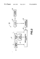
- FIG. 2 shows an example of a recording/reproducing apparatus embodying the present invention.
- FIG. 3 illustrates astigmatic aberration
- FIG. 4 shows an example of a light receiving unit of a photodetector used in the astigmatic aberration method.
- FIG. 5 shows another example of a light receiving unit of a photodetector used in the astigmatic aberration method.
- FIG. 6 shows yet another example of a light receiving unit of a photodetector used in the astigmatic aberration method.
- FIG. 7 illustrates an S-shaped curve appearing in focussing error signals.
- FIG. 8 shows an output of the focussing error signals when the objective lens is moved along the optical axis in a direction approaching the optical disc.
- FIG. 9 shows another embodiment of an optical head embodying the present invention.
- FIG. 10 is a plan view showing an embodiment of a biaxial actuator used in the optical head of FIG. 8 .
- FIG. 11 is a side view showing an embodiment of a biaxial actuator used in the optical head of FIG. 8 .
- FIG. 12 is a perspective view showing an illustrative structure of a lens driving unit.
- FIG. 13 is a plan view showing the lens driving unit shown in FIG. 12 .
- FIG. 14 shows schematics of an optical system of a first embodiment.
- FIG. 15 shows the relation between the thickness error of the light transmitting layer, wavefront aberration and the amount of displacement of a collimator lens of the first embodiment.
- FIG. 16 shows schematics of an optical system of a second embodiment.
- FIG. 17 shows the relation between the thickness error of the light transmitting layer, wavefront aberration and the amount of displacement of a collimator lens of the first embodiment.
- FIG. 1 shows an example of an optical head 1 embodying the present invention.
- This optical head 1 is an optical head used for recording/reproducing a phase-change optical disc 2 .
- the optical head 1 used for recording/reproducing the phase-change optical disc 2 is here taken as an example, the present invention is widely applicable to an optical head for an information recording medium having a light transmitting layer on a recording layer adapted for recording the information signals thereon.
- the information recording medium to be recorded and/or reproduced may be a read-only disc, a magneto-optical disc or an optical card.
- the optical disc 2 recorded/reproduced by the optical head 1 , has a recording layer for recording information signals by phase change, on a substrate 3 of a thickness d of, for example, approximately 1.2 mm or approximately 0.6 mm, while having a light transmitting layer 4 of a thickness t of, for example, approximately 0.1 mm, on the recording layer.
- the light transmitting layer 4 serves as a protective layer for protecting the recording layer.
- the optical disc 2 is designed for recording/reproducing information signals by radiating the light from the side of the light transmitting layer 4 , much thinner in film thickness than the substrate 3 , instead of from the side of the substrate 3 .
- the present invention can, however, be applied to the case of using an information recording medium adapted for recording and/or reproducing information signals with the light incident from the substrate side.
- the optical head 1 includes a light source 10 , a diffraction lattice 11 , a polarizing beam splitter 12 , a collimator lens 13 , an actuator for the collimator lens 14 , a quarter wave plate 15 , an objective lens 16 , a biaxial actuator for the objective lens 17 , a multiple lens 18 and a photodetector 19 .
- the light source 10 radiates light towards the optical disc 2 at the time of recording/reproduction, and is comprised of a semiconductor laser adapted for radiating the linear polarized laser light with a wavelength ⁇ of 650 nm.
- the light source 10 radiates a laser light beam of a constant output.
- the light source 10 modulates the intensity of the outgoing laser light in dependence upon the signals for recording.
- the wavelength ⁇ of the laser light radiated from the light source 10 there is no limitation to the wavelength ⁇ of the laser light radiated from the light source 10 . If the semiconductor laser radiating the laser light of a wavelength shorter than 650 nm, for example, it is advisable to use the laser light of the shorter wavelength in order to realize a higher recording density and a higher recording capacity.
- the laser light radiated from the light source 10 first is incident on and diffracted by the diffraction lattice 1 .
- This diffraction lattice 11 is used for splitting the laser light into at least three portions to enable so-called three-spot tracking servo.
- the 0th order light and the first order light diffracted by the diffraction lattice 11 (collectively termed the incident laser light) is transmitted through the polarizing beam splitter 12 to fall on the collimator lens 13 , which is constituted by bonding two spherical lenses 13 a , 13 b together.
- the collimator lens 13 is an optical device having a pre-set refractive power and, if the thickness t of the light transmitting layer 4 of the optical disc 2 is of a pre-set value, the collimator lens 13 is arranged to collimate the incident laser light.
- the collimator lens 13 is loaded on the actuator for the collimator lens 14 and is thereby moved in the fore-and-aft direction along the optical axis of the incident laser light. If the thickness t of the light transmitting layer 4 of the optical disc 2 is off the prescribed value, the collimator lens 13 is moved by the actuator for the collimator lens 14 to correct the spherical aberration ascribable to the error in thickness of the light transmitting layer 4 .
- the incident laser light is turned by the collimator lens 13 into the diverging light or the converging light to correct the spherical aberration ascribable to the thickness error of the light transmitting layer 4 .
- the incident laser light radiated from the collimator lens 13 , falls on the objective lens via the quarter wave plate 15 .
- the incident laser light is turned into a circular polarized light beam which then falls on the objective lens 16 .
- the objective lens 16 is used for collecting the light on the recording layer of the optical disc 2 .
- the incident laser light turned into the circular polarized light beam, is converged by the objective lens 16 to fall on the recording layer of the optical disc 2 via the light transmitting layer 4 of the optical disc 2 .
- the objective lens 16 may be of a sole lens, it may also be constituted by bonding two lenses 16 a , 16 b together, as shown in FIG. 1 . If the objective lens 16 is constructed from two lenses 16 a , 16 b , the lens can be fabricated easily, even if the numerical aperture NA is enlarged, without it being necessary to use an excessive strict tolerance for the curvature of the respective lens surfaces. That is, by constructing the objective lens 16 from the two lenses 16 a , 16 b , it is easily possible to enlarge the numerical aperture NA to realize higher recording density and higher recording capacity.
- the objective lens 16 may be constructed from three or more lenses. By constructing the objective lens 16 from three or more lenses, it is possible to moderate the curvature of the respective lens surfaces. However, if the number of the lenses is excessive, it becomes difficult to combine the lenses to high accuracy. Therefore, it is desirable to construct the objective lens from two lenses.
- This return light beam is transmitted through the objective lens 16 to fall on the quarter wave plate 15 .
- This return light is first transmitted through the objective lens 16 by tracing the original optical path and is transmitted through the quarter wave plate 15 so as to be turned into a linear polarized light beam 90° rotated with respect to the polarizing direction of the ongoing light.
- the return light is then collimated by the collimator lens 13 to be incident on and reflected on the polarizing beam splitter 12 .
- the return light reflected by the polarizing beam splitter 12 is incident on and detected by the photodetector 19 via the multiple type lens 18 .
- the multiple type lens 18 has a cylindrical light incident surface and a concave light outgoing surface.
- the multiple type lens 18 operates for according the astigmatic aberration to the return light to enable focussing servo by the so-called astigmatic aberration method.
- the photodetector 19 adapted for detecting the return light, to which the astigmatic aberration has been accorded by the multiple type lens 18 , includes six photodiodes, as an example.
- the photodetector 19 outputs electrical signals proportionate to the light intensity of the return light falling on the respective photodiodes and executes pre-set calculations on the electrical signals to generate and output servo signals such as focussing servo signals or tracking servo signals.
- the photodetector 19 detects the return light, to which the astigmatic aberration has been accorded by the multiple lens 18 , to generate and output focussing servo signals by the so-called astigmatic aberration method. Based on these focussing servo signals, the optical head 1 drives the biaxial actuator for the objective lens 17 , carrying the objective lens 16 , in order to perform focussing servo.
- the photodetector 19 also detects the return light beams of the zeroth order light and the ⁇ first order light, diffracted by the diffraction lattice 11 , to generate tracking servo signals by the so-called three-beam method to output the resulting tracking servo signals. Based on these tracking servo signals, the optical head 1 drives the biaxial actuator for the objective lens 17 , carrying the objective lens 16 , in order to perform tracking servo.
- the photodetector 19 When reproducing information signals from the optical disc 2 , the photodetector 19 also processes electrical signals corresponding to the light intensity of the return light incident on the respective photodiodes with preset calculations to generate and output playback signals from the optical disc 2 .
- the objective lens 16 is loaded on the biaxial actuator for the objective lens 17 to effect tracking servo and focussing servo.
- the objective lens 16 is loaded on the biaxial actuator for the objective lens 17 to effect tracking servo and focussing servo.
- only focussing servo may be applied as the servo performed by moving the objective lens by an actuator, while the tracking servo may be applied by moving the entire optical head.
- the aberration ascribable to errors in thickness of the light transmitting layer 4 of the optical disc 2 is produced mainly by defocussing or due to spherical aberration.
- the defocussing is corrected by focussing servo. That is, the objective lens 16 is moved along its optical axis in the fore-and-aft direction by the biaxial actuator for the objective lens 17 to correct the defocussing to effect focussing on the recording layer. This correction for defocussing is performed on conventional optical heads.
- the spherical aberration cannot be corrected by moving the objective lens in the fore-and-aft direction along the optical axis.
- the spherical aberration can be corrected by exchanging the objective lens 16 or by changing the refractive index of the optical medium of the objective lens 16 depending on the thickness t of the light transmitting layer 4 .
- these techniques cannot be said to be realistic.
- the collimator lens 13 is moved in the fore-and-aft direction along the optical axis by the actuator for the collimator lens 14 to correct the spherical aberration ascribable to the thickness error of the light transmitting layer 4 . That is, with the present optical head 1 , the actuator for the collimator lens 14 serves as movement means for moving the collimator lens 13 for cancelling the spherical aberration depending on the thickness t of the light transmitting layer 4 of the optical disc 2 .
- the spherical aberration produced due to error in thickness of the light transmitting layer 4 and the method for correcting the aberration are explained in detail.
- ⁇ t is a thickness error of the light transmitting layer
- n is the refractive index of the light transmitting layer
- NA is the numerical aperture of an objective lens
- This equation (1) is obtained from a Taylor expansion of the total aberration quantity with the numerical aperture NA of the objective lens and converted to a wavefront aberration. That is, if the numerical aperture NA is represented by the sine function and expanded, the following equation (3):
- the wavefront aberration as found from the third term of the right side of the equation (3) is a quantity termed the degree five spherical aberration W 50 represented by the following equation (4):
- W 50 ⁇ t ( n 2 ⁇ 1)( n 2 +3)/48 n 5 ⁇ NA 6 (4).
- ⁇ S ⁇ t ( n 2 ⁇ 1)/2 n 3 ⁇ NA 3 [1+ ⁇ ( n 2 +3)/4 n 2 ⁇ NA 2 ] (6).
- the degree-three spherical aberration W 40 can be represented by the sum of the aberrations produced on the respective optical planes. Thus, if these is present only the degree-three spherical aberration W 40 , it can be corrected by arranging an optical element producing spherical aberration of the opposite sign somewhere between the light source 10 and the light transmitting layer 4 .
- the degree-three spherical aberration W 40 is maximum for the refractive index n of the light transmitting layer 4 of 3 1 ⁇ 2 ( ⁇ 1.732) and is decreased abruptly when the refractive index n of the light reflecting layer 4 is smaller than the above value.
- the refractive index n of the light transmitting layer 4 usually is of the order of 1.5.
- the numerical aperture NA of the objective lens 16 is increased as described above, the contribution of the degree-five spherical aberration W 60 is increased. This increase in the degree-five spherical aberration W 60 cannot be disregarded. If, for example, the numerical aperture NA is increased such that the proportion of the degree-five spherical aberration in the entire spherical aberration becomes maximum, it may be an occurrence that the degree-five spherical aberration W 60 accounts for approximately 40% of the total spherical aberration. Therefore, in a system with a larger value of the numerical aperture NA, it is necessary to take the effect of the degree-five spherical aberration W 60 sufficiently into consideration.
- the total aberration ascribable to the thickness error ⁇ t of the light transmitting layer 4 is not larger than 1.452 ⁇ m.
- the numerical aperture NA is 0.85, the degree-five spherical aberration W 60 , in particular, is increased, such that the total aberration is as much as 4.850 ⁇ m at the maximum.
- NA 0 , n1 and NA 1 are a refractive index of the light incident side of the collimator lens 13 , the refractive index of the light transmitting layer 4 and the numerical aperture of the objective lens 16 .
- the NA 1 of the objective lens 16 and the NA 0 of the light incident side of the collimator lens 13 need to be of the same order of magnitudes, if the actually feasible value of the refractive index is taken into consideration. Specifically, at least the relation NA 1 /NA 0 ⁇ 2 needs to be met. It is however not realistic to increase the value of the NA 0 of the light incident side of the collimator lens 13 in keeping with the increase in the NA 1 of the objective lens 16 . Thus, with the method of inserting the parallel planar plate between the light source 10 and the collimator lens 13 , it is not possible to correct the spherical aberration completely.
- the well-balanced correction is realized by causing movement of three-dimensional collimator lens 13 along the optical axis by the actuator for the collimator lens 14 .
- the numerical aperture NA of the light incident side of the objective lens 16 is changed to correct the spherical aberration.
- the diameter of the exit pupil of the collimator lens 13 is desirably sufficiently larger than the diameter of the entrance pupil of the objective lens 16 .
- the numerical aperture NA of the light exit side of the objective lens 16 is maintained substantially constant, even if the numerical aperture NA of the objective lens 16 is varied, thus assuring stable recording/reproduction.
- the numerical aperture NA of the light incident side of the collimator lens 13 is set mainly with a view to enhancing the coupling efficiency with the incident laser light radiated from the light source.
- the numerical aperture NA is preferably set to approximately 0.3 or less.
- a larger value of the numerical aperture NA of the objective lens 16 is preferred for reducing the diameter of the light converged on the recording layer. If it is desired to realize high recording density and high recording capacity exceeding those of the DVD, this numerical aperture NA is desirably set to not less than 0.65.
- the numerical aperture NA on the light incident side of the collimator lens 13 is desirably set to a value significantly smaller than the value of the numerical aperture NA on the light exit side of the objective lens 16 .
- the spherical aberration produced due to the movement along the optical axis of the collimator lens 13 is mainly the degree-three spherical aberration W 40 . Therefore, it is not possible to remove the entire spherical aberration ascribable to the thickness error ⁇ t of the light transmitting layer 4 completely by the movement of the collimator lens 13 .
- the position of destination of movement of the collimator lens 13 is set so that the mean square value of the aberration will be minimum.
- the optical path difference of the main light beam and the ambient light beam is calculated by the light tracking method and the collimator lens position which will give the minimum value of the mean square value of the optical path difference, that is the wavefront aberration, is previously calculated.
- the thickness t of the light transmitting layer 4 is detected and the collimator lens 13 is moved by the actuator for the collimator lens 14 to a position previously calculated depending on an error ⁇ t.
- the distance of movement of the collimator lens 13 is sufficiently smaller than the focal length of the collimator lens 13 so that the wavefront aberration W,S generated by the movement of the collimator lens 13 will be sufficiently smaller than the focal length of the collimator lens 13 .
- the amount of movement of the collimator lens 13 is subsequently proportionate to the amount of the spherical aberration produced by the movement of the collimator lens 13 , thus simplifying the structure and the driving method etc of the actuator for the collimator lens 14 .
- the spherical aberration attributable to the thickness error ⁇ t of the light transmitting layer 4 is corrected by movement of the collimator lens 13 .
- the spherical aberration attributable to the thickness error ⁇ t of the light transmitting layer 4 may be corrected by any suitable optical device other than the collimator lens.
- the optical element used for correcting the spherical aberration attributable to the thickness error ⁇ t of the light transmitting layer 4 is arranged between the light source 10 and the objective lens 16 .
- a lens provided between the light source 10 and the collimator lens 13 may be moved in the fore-and-aft direction along the optical axis.
- the collimator lens 13 may be omitted and the light radiated from the light source 10 may be caused to fall in the state of the divergent light on the objective lens 16 .
- the lens is provided on the optical path of the divergent light incident on the objective lens 16 and is moved in the fore-and-aft direction along the optical axis.
- the collimator lens 13 is desirably used as an optical device for spherical aberration correction as in the case of the optical head 1 .
- the numerical aperture NA is preferably set to not less than 0.65, as discussed previously.
- the numerical aperture NA of the objective lens 16 is increased, there is raised a problem of increased coma aberration, besides that of the above-described spherical aberration.
- the coma aberration is generated by the radial tilt of the optical disc 2 , termed the radial skew, and is increased in proportion to the third power of the numerical aperture NA of the objective lens 16 .
- the numerical aperture NA it becomes more crucial to suppress the coma aberration.
- the skew of the radial skew is ⁇ 0.4° and, for maintaining the comparable tolerance value, it suffices if the thickness t of the light transmitting layer 4 is set to satisfy the following equation (9):
- the thickness t of the light transmitting layer 4 is preferably set to 0.47 mm or less.
- the numerical aperture NA of the objective lens 16 is set to not less than 0.65 to achieve the high recording density, it is possible to maintain the tolerance of the thickness t of the light transmitting layer 4 of a value comparable to that of the conventional DVD.
- NA of the objective lens 16 is increased further so that NA ⁇ 0.7, preferably t ⁇ 0.37 mm. If the numerical aperture NA is increased still further so that NA ⁇ 0.85, preferably t ⁇ 0.21 mm.
- the thickness t of the light transmitting layer 4 is reduced sufficiently in keeping with the numerical aperture NA of the objective lens 16 to increase the numerical aperture NA of the objective lens 16 to increase the recording density, the radial skew tolerance can be kept at a value comparable to the value of the conventional DVD. Therefore, by reducing the thickness t of the light transmitting layer 4 in keeping with the increase in the numerical aperture NA, it is possible to achieve higher recording density without prohibitive cost rise due to excessive narrowing of the radial skew tolerance.
- a recording/reproducing apparatus 30 having the optical head 1 for recording/reproducing the optical disc 2 , as shown in FIG. 2, is hereinafter explained.
- the information recording medium to be recorded and/or reproduced may be a read-only optical disc, a magneto-optical disc or an optical card.
- the recording/reproducing apparatus 30 includes a spindle motor 31 for rotationally driving an optical disc 2 , the optical head 1 used for recording/reproducing information signals, a feed motor 32 for moving the optical head 1 , a modem circuit 33 for performing a modulating/demodulating operation, a servo control circuit 34 for servo-controlling the optical head 1 and a system controller 35 for controlling the entire system.
- the spindle motor 31 is driven under control by the servo control circuit 34 and is run in rotation at a pre-set rpm. That is, the optical disc 2 to be recorded or reproduced is chucked by the spindle motor 31 and run in rotation at a pre-set rpm by the spindle motor 31 rotationally driving by the servo control circuit 34 .
- the optical head 1 When recording/reproducing information signals, the optical head 1 illuminates the laser light on the optical disc 2 , run in rotation by the optical disc 2 , to detect the return light.
- signals sent from an external circuit 36 and modulated in a pre-set manner by the modem circuit 33 are sent to the optical head 1 , which then illuminates a laser light beam, modulated in light intensity, on the optical disc 2 .
- the optical head 1 When reproducing information signals, the optical head 1 illuminates a laser light beam of a constant output on the rotating optical disc 2 and generates playback signals from the return light to send the playback signals to the modem circuit 33 .
- the optical head 1 is also connected to the servo control circuit 34 . During recording/reproduction of information signals, the optical head 1 generates focussing servo signals and tracking servo signals, from the return light reflected from the rotating optical disc 2 , as described above, to send the servo signals to the servo control circuit 34 .
- the modem circuit 33 is connected to the system controller 35 and to the external circuit 36 .
- the modem circuit 33 receives the signals recorded on the optical disc 2 from the external circuit 36 , under control by the system controller 35 , and modulates the received signals.
- the signals modulated by the modem circuit 33 are sent to the optical head 1 .
- the modem circuit 33 receives the signals reproduced from the optical disc 2 , under control by the system controller 35 , to modulate the layback signals.
- the signals demodulated by the modem circuit 33 are outputted from the modem circuit 33 to the external circuit 36 .
- the feed motor 32 is adapted to feed the optical head 1 to a pre-set position along the radius of the optical disc 2 , and is driven by control signals from the servo control circuit 34 . That is, this feed motor 32 is connected to and controlled by the servo control circuit 34 .
- the servo control circuit 34 controls the feed motor 32 , under control by the system controller 35 , so that the optical head 1 will be fed to a pre-set position facing the optical disc 2 .
- the servo control circuit 34 is also connected to the spindle motor 31 to control the operation of the spindle motor 31 under control by the system controller 35 . That is, the servo control circuit 34 controls the spindle motor 31 so that the optical disc 2 will be rotationally driven at a pre-set rpm during recording/reproduction of the information signals.
- the servo control circuit 34 is also connected to the optical head 1 and receives the servo signals from the optical head 1 during recording/reproduction of information signals to effect focussing servo control and tracking servo control by the biaxial actuator for the objective lens 17 loaded on the optical head 1 based on the servo signals.
- the servo control circuit 34 also operates as detection means for detecting the thickness t of the light transmitting layer 4 of the optical disc 2 based on the focussing servo signals.
- the method for detecting the thickness of the light transmitting layer 4 by the servo control circuit 34 is hereinafter explained.
- focussing servo signals sent from the photodetector 19 of the photodetector 1 to the servo control circuit 34 , there are focussing pull-in signals and focussing error signals.
- the focussing pull-in signals indicate the light volume of the entire return light reflected from the optical disc 2 and are used for causing movement of the objective lens 16 to near the focussing position.
- the focussing error signals hold the objective lens 16 in the just-focus position after the objective lens 1 is moved to near the focussing position based on the focussing pull-in signals.
- the recording/reproducing apparatus 30 acquires the focussing error signals based on the astigmatic aberration method.
- an optical element such as a parallel planar plate formed by a glass plate is arranged in a converging optical path of the return light to generate intentionally a large astigmatic aberration to detect a beam shape ahead or at back of the circle of least confusion to derive focussing error signals.
- the astigmatic aberration method is explained by taking an example of using a parallel flat plate 20 , as shown in FIG. 3 .
- the optical head 1 shown in FIG. 1 uses a multiple lens 18 as an optical component for generating the astigmatic aberration
- the parallel flat plate 20 is used here as an optical element producing the astigmatic aberration for simplicity.
- ⁇ , n and t denote the angle of the optical return opening, the refractive index of the parallel flat plate 20 arranged in the finite light and its thickness, respectively.
- FIGS. 4 to 6 show a light receiving section 21 of a photodetector adapted for detecting the focussing error signals by the astigmatic aberration method.
- This light receiving section 21 is rectangular in shape and is split into four segments by two perpendicular splitting lines.
- the beam spot 22 on the lead-in area 21 is of an elliptical shape, as shown in FIG. 4 .
- the beam spot 22 on the light receiving section 21 is of an elliptical shape, as shown in FIG. 5 .
- the light volume in the respective segments of the light receiving section 21 is (A+C) ⁇ (B+D), with FE ⁇ 0.
- the beam spot 22 on the light receiving section 21 is of an elliptical shape, as shown in FIG. 6 .
- the light volume in the respective segments of the light receiving section 21 is (A+C)>(B+D), with FE>0.
- the focussing error signals are represented by an S-shaped curve, as shown in FIG. 7, if the focussing deviation is plotted on the abscissa and the output of the focussing error signals is plotted on the ordinate.
- a null point at the center of the S-shaped curve represents a just-focus point.
- a range Wa from one of the peaks Pa to the opposite side peak Pb of the S-shaped curve is generally termed a focussing pull-in range.
- the biaxial actuator for the objective lens 17 is driven, as the focussing pull-in signals are detected, in order to cause movement of the objective lens 16 in the fore-and-aft direction along the optical axis.
- the focal point of the objective lens is caused to be positioned near the recording layer based on the focussing pull-in signals.
- the objective lens 16 When the focal point of the objective lens 16 is positioned near the recording layer and the objective lens 16 is in the focussing pull-in range, the objective lens 16 is subsequently moved in the fore-and-aft direction along the optical axis by the biaxial actuator for the objective lens 17 so that the just-focus position is perpetually maintained; that is, so that the focussing error signals will perpetually be at the zero point. This perpetually sets the focussed state with respect to the recording layer.
- the principle of the focussing servo is as described above.
- the focussing error signals FE by the return light reflected from the recording layer are used to effect the focussing servo.
- the incident laser light is reflected not only by the recording layer but also by the surface of the optical disc 2 , that is on the surface of the light transmitting layer 4 , albeit to a lesser extent.
- the S-shaped curve shown in FIG. 7 appears due to the return light reflected by the surface of the light transmitting layer 4 .
- the S-shaped curve appearing in the focussing error signals due to the return light reflected by the surface of the light transmitting layer 4 is termed a first S-shaped curve, while that appearing in the focussing error signals due to the return light reflected by the recording the layer of the optical disc 1 is termed a second S-shaped curve.
- the recording/reproducing apparatus 30 detects the thickness t of the light transmitting layer 4 based on the focussing error signals corresponding to the first and second S-shaped curves. That is, in the recording/reproducing apparatus 30 of the present invention, the objective lens 16 is moved along the optical axis by the biaxial actuator for the objective lens 17 , prior to the recording/reproducing operation, until the focal position of the objective lens reaches from the surface of the light transmitting layer 4 to the recording layer. The thickness t of the light transmitting layer 4 is detected based on the movement speed of the objective lens 16 and the focussing error signals corresponding to the first and second S-shaped curves.
- FIG. 8 showing the output of the focussing error signals when the objective lens 16 is moved along the optical axis in a direction approaching the optical disc 2 , the abscissa and the ordinate represent the time and the output of the focussing error signals, respectively.
- W 1 is the time necessary for the objective lens 16 to traverse the focussing pull-in range in the first S-shaped curve. That is, W 1 denotes the time which elapses until the focussing error signals move from the maximum value to the minimum value on the first S-shaped curve by the movement of the objective lens 16 , while P 1 denotes a point of focusing on the surface of the light transmitting layer 4 of the optical disc 2 , that is the just-focus point with respect to the surface of the light transmitting layer 4 .
- W 2 is the time necessary for the objective lens 16 to traverse the focussing pull-in range in the second S-shaped curve. That is, W 2 denotes the time which elapses until the focussing error signals move from the maximum value to the minimum value on the second S-shaped curve by the movement of the objective lens 16 , while P 2 denotes a point of focusing on the surface of the light transmitting layer 4 of the optical disc 2 , that is, the just-focus point with respect to the recording layer.
- W 3 denotes the time which elapses from the point PI focussed on the surface of the light transmitting layer 4 of the optical disc 2 until the point P 2 focussed on the recording layer of the optical disc 2 .
- the thickness t of the light transmitting layer 4 is given by the following equation (11):
- the length of the focussing pull-in range A is set to 20 ⁇ m or thereabouts in a majority of currently used optical heads
- the servo control circuit 34 finds the thickness t of the light transmitting layer 4 based on the above equation (11).
- the servo control circuit 34 of the recording/reproducing apparatus 30 operates as thickness detection means for detecting the thickness t of the light transmitting layer 4 .
- the thickness t of the light transmitting layer 4 can be detected only once, it is preferably detected a number of times on end to find an average value. That is, in detecting the thickness t of the light transmitting layer 4 , the biaxial actuator for the objective lens 17 is repeatedly moved back and forth at a pre-set frequency, such as at 100 to 200 Hz, to find the thickness t of the light transmitting layer 4 repeatedly to find its average value. This enables more accurate detection of the thickness t of the light transmitting layer 4 .
- the servo control circuit 34 which has detected the thickness t of the light transmitting layer 4 as described above, sends a control signal to the optical head 1 in order to cause movement of the collimator lens 13 by the actuator for the collimator lens 14 to minimize the spherical aberration attributable to the thickness error of the light transmitting layer 4 based on the control signal.
- the recording/reproducing apparatus 30 After correcting the spherical aberration attributable to the thickness error of the light transmitting layer 4 , the recording/reproducing apparatus 30 performs the recording/reproducing operation, as in the case of the conventional recording/reproducing apparatus.
- the thickness t of the light transmitting layer 4 is measured prior to the recording/reproducing operation to correct the spherical aberration attributable to the thickness error.
- the thickness t of the light transmitting layer 4 is measured prior to the recording/reproducing operation to correct the spherical aberration attributable to the thickness error.
- an optical head of the present invention it is sufficient if an optical element having a pre-set refractive power is moved to cancel the spherical aberration depending on the thickness of the light transmitting layer and hence the optical head is not limited to the structure shown in FIG. 1 .
- FIGS. 9 to 11 modifications of the optical head of the present invention are explained in detail.
- An optical head 100 shown in FIG. 9, is an optical head used in recording/reproducing a phase-change optical disc 101 .
- An optical disc 101 adapted to be recorded/reproduced by the optical head 100 , has a substrate 102 , a recording layer formed thereon for recording information signals by phase change and a light transmitting layer 103 formed on the recording layer.
- the optical disc 101 is recorded or reproduced by the light incident on the side of the light transmitting layer 103 .
- the optical head 100 includes a first optical system 104 for detecting the thickness of the light transmitting layer 103 of the optical disc 101 and a second optical system 105 .
- the second optical system 105 corrects the spherical aberration attributable to the thickness error of the light transmitting layer 103 of the optical disc 101 based on the thickness of the light transmitting layer 103 of the optical disc 101 detected by the first optical system 104 .
- the first optical system 104 includes a light source 106 , a polarizing beam splitter 107 , a collimator lens 108 , an objective lens 109 and a photodetector 110 .
- the light source 106 radiates light to the optical disc 101 .
- a semiconductor laser emitting a short-wavelength laser with the wavelength of 635 to 650 nm is used as the light source 106 .
- the laser light emitted by the light source 106 is reflected by the polarizing beam splitter 107 to fall on the collimator lens 108 .
- the laser light incident on the collimator lens 108 is collimated by the collimator lens 108 , which is composed of two spherical lenses 108 a, 108 b bonded together.
- the laser light, collimated by the collimator lens 108 falls on the objective lens 109 .
- the laser light incident on the objective lens 109 is converged by the objective lens 109 to fall via the light transmitting layer 103 on the recording layer of the optical disc 101 .
- the objective lens 109 is loaded on a biaxial actuator 111 so as to be moved in a direction along the optical axis and in a direction perpendicular thereto.
- the laser light converged by the objective lens 109 to fall on the recording layer of the optical disc 101 is reflected by the recording layer as a return light beam.
- This return light beam is caused to retrograde along the original optical path to traverse the polarizing beam splitter 107 so as to be incident on and detected by the photodetector
- the first optical system 104 detects the thickness of the light transmitting layer 103 of the optical disc 101 from the focussing error signals on the surface of the light transmitting layer 103 and the recording layer of the optical disc 101 .
- the second optical system 105 includes a light source 112 , a cylindrical lens 113 , a polarizing beam splitter 114 , a collimator lens 115 , a diffraction lattice 116 , an optical path uplifting mirror 117 , a quarter wave plate 118 , a set of two objective lenses 119 and a photodetector 120 .
- the light source 112 comprised of a semiconductor laser emitting a short-wavelength laser of the wavelength of 400 to 650 nm, radiates light towards the optical disc 101 .
- the laser light radiated from the light source 112 falls on the cylindrical lens 113 .
- the laser light incident on the collimator lens 115 is beam-shaped by the cylindrical lens 113 and thence transmitted through the polarizing beam splitter 114 to fall on the collimator lens 115 .
- the laser light is incident on and collimated by the collimator lens 1 , which is comprised of two spherical lenses bonded together.
- This collimator lens 115 is loaded on an actuator for the collimator lens 121 and is thereby moved back and forth along the optical axis of the incident laser light.
- the collimator lens 115 is collimated by the collimator lens 115 to correct the spherical aberration ascribable to the thickness error of the light transmitting layer 103 . That is, if the thickness t of the light transmitting layer 103 of the optical disc 101 is off the prescribed value, the incident laser light is turned by the collimator lens 115 into a diverging light or the converging light in order to correct the spherical aberration ascribable to the thickness error of the light transmitting layer 103 . The laser light outgoing from the collimator lens 115 falls on the diffraction lattice 116 .
- the laser light incident on the diffraction lattice 116 is diffracted by the diffraction lattice 116 into a three-beam laser light.
- This diffraction lattice 116 serves for splitting the laser light into at least three beams to enable tracking servo by the so-called three-spot method.
- the laser light radiated from the diffraction lattice 116 has its proceeding direction bent by the optical path uplifting mirror 117 to fall on the quarter wave plate 118 .
- the laser light incident on the quarter wave plate 118 is turned from the linear polarized state to a circular polarized state.
- the laser light outgoing from the quarter wave plate 118 falls on the set of two objective lenses 119 .
- the laser light incident on the set of two objective lenses 119 is converged thereby to fall on the recording layer of the optical disc 101 via the light transmitting layer 103 .
- the set of two objective lenses 119 made up of two lenses 119 a, 119 b, is loaded on the biaxial actuator 111 and is thereby moved in the direction along the optical axis and in the direction perpendicular thereto.
- the resulting converged light is reflected by the polarizing beam splitter 114 so as to be incident on and detected by the photodetector 120 .
- the second optical system 105 includes a converging lens 122 for converging the laser light reflected by the polarizing beam splitter 114 and an output adjustment photodetector 123 for receiving the laser light converged by the converging lens 122 for automatically adjusting an output of the laser light radiated from the light source 112 based on the received light volume.
- the objective lens 109 of the first optical system 104 and the set of two objective lenses 119 of the second optical system 105 are loaded on the biaxial actuator 111 and are thereby moved in the biaxial directions to effect tracking control and focussing control for the optical disc 101 .
- FIGS. 10 and 11 show an illustrative structure of the biaxial actuator 111 .
- This biaxial actuator 111 includes a bobbin 130 carrying the objective lens 109 and the set of two objective lenses 119 and an electromagnetic driving mechanism 131 for causing movement of the bobbin 130 in two perpendicular directions.
- the bobbin 130 is formed substantially as a cylinder having a top plate and has its center supported by a supporting shaft 132 .
- the bobbin 130 is supported for rotation about and for sliding along the axis of the supporting shaft 132 .
- the objective lens 109 and the set of two objective lenses 119 are mounted on this bobbin 130 in point symmetry on both sides of the supporting shaft 132 so that the optical axes thereof run parallel to each other.
- the electromagnetic driving mechanism 131 for causing movement of the bobbin 130 includes a magnetic circuit having a focussing magnet 133 , a pair of focussing yokes 134 , 135 , a tracking magnet 136 , a pair of tracking yokes 137 , 138 , a focussing coil 139 and a tracking coil 140 .
- a metal piece 141 for setting the neutral position of the bobbin 130 , as shown in FIG. 11 .
- the metal piece 141 being attracted towards the boundary of the two poles of the tracking magnet 136 split into the two planar poles, the bobbin 130 is set at the neutral position in the tracking direction as the second direction, while being set at the neutral position in the focussing direction as the first direction.
- the bobbin 130 is held on a supporting base block 142 , carrying the supporting shaft 132 , at a neutral position by a neutral position supporting mechanism constituted by resilient rubber etc.
- the bobbin 130 thus kept at the neutral position, is slid along the axis of the supporting shaft 132 and rotated about the axis of the supporting shaft 132 , under driving by the electromagnetic driving mechanism 131 .
- the electromagnetic driving mechanism 131 causes the bobbin 130 to be moved along the axis of the supporting shaft 132 by the focussing error signals being sent via a flexible substrate 143 to the focussing coil 139 .
- focussing control is performed on the set of two objective lenses 119 with respect to the optical disc 101 .
- the electromagnetic driving mechanism 131 causes the bobbin 130 to be rotated about the axis of the supporting shaft 132 by the tracking error signals being sent via a flexible substrate 143 to the tracking coil 140 .
- tracking control is performed on the set of two objective lenses 119 with respect to the optical disc 101 .
- the so-called astigmatic aberration method and three-spot method are used as the focussing servo and tracking servo methods, respectively.
- the astigmatic aberration method detects the reflected laser light from the optical disc via a cylindrical lens and so forth by a four-segment photodetector and finds the sum and/or the difference of detection outputs obtained from the respective segments to derive focussing error signals as the defocussing components of the laser light with respect to the recording layer.
- the three-spot method splits a sole laser light beam, outgoing from the light source, into a sole main laser light beam (zeroth order beam) and two sub-beams ( ⁇ first order beam), using a diffraction lattice and so forth, to illuminate the two sub-beams ahead and at back of the main laser light beam illuminated on the recording track center.
- the reflected light beams of the sub-beams illuminated ahead and at back of the main laser light beam are detected by a photodetector having two light receiving sections to find the difference between the detection outputs derived from the light receiving sections to derive the tracking error signals as the offset components of the main light beam with respect to the recording track.
- the first optical system 104 detects the thickness of the light transmitting layer 103 of the optical disc 101 from the focussing error signals on the recording layer and the surface of the light transmitting layer 103 of the optical disc 101 . That is, the biaxial actuator 111 of the first optical system 104 causes movement of the objective lens 109 back and forth along the optical axis by the biaxial actuator 111 to detect the thickness of the light transmitting layer 103 from the equation (11) based on the movement speed of the objective lens 109 and the first and second S-shaped curves exhibited in the focussing error signals.
- the control circuit which has determined the thickness of the light transmitting layer 103 , determines the operation for correcting the spherical aberration ascribable to the thickness error of the optical disc 101 and sends out control signals instructing the operation thereof to the second optical system 105 .
- the second optical system 105 causes the functional or stepped movements of the collimator lens 115 by the actuator for the collimator lens 121 for minimizing the spherical aberration ascribable to the thickness error of the light transmitting layer 103 .
- the second optical system 105 After correcting the spherical aberration ascribable to the thickness error of the light transmitting layer 103 , the second optical system 105 effectuates the recording/reproducing operation for the optical disc 101 .
- the actuator for the collimator lens 115 By moving the collimator lens 115 to its optimum position in this manner by the actuator for the collimator lens 115 , the spherical aberration produced due to the thickness error of the light transmitting layer 103 can be corrected to produce optimum signals.
- the first optical system 104 operates as an optical system for detecting the working distance in the second optical system 105 , that is the separation between the optical disc 101 and the set of two objective lenses 119 .
- the focussing pull-in range is narrow, because of the high NA of the set of two objective lenses 119 , such that the working distance between the optical disc 101 and the set of two objective lenses 119 is e.g., not larger than 0.5 mm.
- the optical disc 101 is subjected to surface deviations or the height of the optical disc 101 is deviated from a reference value, there is a risk that the optical disc 101 collides against the set of two objective lenses 119 during focussing pull-in operation.
- the first optical system 104 is used as auxiliary means to prohibit collision of the optical disc 101 against the set of two objective lenses 119 .
- the laser light radiated from the light source 106 is illuminated on the optical disc 101 and the reflected light is received by the photodetector 110 to detect focussing error signals. Based on these focussing error signals, approximate positions of the set of two objective lenses 119 loaded on the bobbin used in common with the objective lens 109 of the first optical system 104 is detected. Based on the position information of the set of two objective lenses 119 , as detected by the first optical system 104 , the optical head 100 actuates the biaxial actuator 111 to prohibit collision of the optical disc 101 against the set of two objective lenses 119 .
- the set of two objective lenses 119 has deviated the focussing pull-in range of the first optical system 104 significantly, it is also not possible for the first optical system 104 to produce focussing error signals.
- the entire reflected light from the optical disc 101 then is detected by the first optical system 104 and, based on the detected level, the set of two objective lenses 119 is pulled into the focussing pull-in range i-the first optical system 104 .
- the first optical system 104 is used as an auxiliary optical system for focussing pull-in for reproducing the optical disc 101 by the second optical system 105 , positive focussing pull-in can be realized, despite surface or height deviations of the optical disc 101 , without collision of the set of two objective lenses 119 against the optical disc 101 .
- the auxiliary function for focussing pull-in for the first optical system 104 or the working distance detection method can be realized by methods other than the astigmatic aberration method, such as a differential concentric circle method.
- the optical head 1 uses the actuator for the collimator lens 14 as movement means for the collimator lens 13 in a direction of cancelling the spherical aberration depending on the thickness of the light transmitting layer 4 of the optical disc 2 .
- the optical head 1 also uses the actuator for the collimator lens 121 as movement means for causing movement of the collimator lens 115 in a direction of cancelling the spherical aberration depending on the thickness of the light transmitting layer 103 of the optical disc 101 .
- FIGS. 12 and 13 an illustrative structure of these movement means (termed herein a lens driving mechanism) is now explained.
- a lens driving mechanism 160 shown in FIGS. 12 and 13, causes movement of the collimator lens in a direction of cancelling the spherical aberration depending on the thickness of the light transmitting layer of an information recording medium.
- the lens driving mechanism 160 thus includes a reference shaft 161 arranged parallel to the optical axis, a sub-reference shaft 162 arranged parallel to the optical axis, and a collimator lens holder 163 supported by these reference shafts 161 , 162 .
- the reference shaft 161 and the sub-reference shaft 162 are mounted on and secured to a stationary portion of the optical head.
- the collimator lens holder 163 is supported for sliding movement along the optical axis relative to these reference shafts 161 , 162 .
- the collimator lens moved for cancelling the spherical aberration, is loaded on this collimator lens holder 163 . That is, by causing movement of the collimator lens holder 163 back and forth along the reference shafts 161 , 162 , the lens driving mechanism 160 causes translating movement of the collimator lens loaded on the collimator lens holder 163 back and forth relative to the optical axis direction.
- the lens driving mechanism 160 also includes, as a driving mechanism for causing movement of the collimator lens holder 163 back and forth along the reference shaft 161 and the sub-reference shaft 162 , a dc motor 164 , as a driving source for causing movement of the collimator lens holder 163 , and a gearing 165 for converting the rotational movement of the dc motor 164 into a translating movement along the optical axis to transmit the translating movement to the collimator lens holder 163 .
- the collimator lens By converting the rotation of the collimator lens holder 163 by the gearing 165 into a translating movement along the optical axis for causing movement of the collimator lens holder 163 , the collimator lens is moved in a direction of cancelling the spherical aberration depending on the thickness of the light transmitting layer of the information recording medium.
- the gearing 165 includes a rack 166 , mounted on the collimator lens holder 163 , a first gear 167 mounted on the rotary shaft of the dc motor 164 for transmitting the power of rotation of the dc motor 164 , a second gear 168 for converting the rotation of the dc motor 164 to a translating movement along the optical axis and a third gear 169 for transmitting the driving power converted into the translating movement along the optical axis by the second gear 168 to a rack 166 .
- the lens driving mechanism 160 includes a base block 170 , mounted on the stationary portion of the optical head.
- the dc motor 164 , second gear 168 and the third gear 169 are mounted on this base block 170 .
- the rack 166 to which the driving power is transmitted from the third gear 169 , is of a double-rack structure of two racks 166 a, 166 b for removing the backlash between the rack 166 and the third gear 169 . These racks 166 a, 166 b are interconnected by a spring 171 .
- the dc motor 164 is rotated, thereby rotating the first gear 167 .
- This rotation of the first gear 167 is transmitted to the second gear 168 for conversion to the translating movement along the optical axis.
- the driving power, converted by the second gear 168 into the translating movement along the optical axis, is transmitted via the third gear 169 to the rack 166 .
- This rack 166 is mounted on the collimator lens holder 163 which is supported for sliding along the optical axis with respect to the reference shafts 161 , 162 .
- the collimator lens holder 163 is moved along the optical axis by the driving force transmitted via the third gear 169 to the rack 166 to cause movement of the collimator lens carried by the collimator lens holder 163 along the optical axis.
- the collimator lens can be moved highly accurately.
- the spherical aberration ascribable to variations in the thickness of the light transmitting layer can be cancelled out sufficiently.
- the lens driving mechanism 160 a pulse driving type stepping motor is used as the dc motor 164 , and the movement distance of the collimator lens per one-pulse rotation is 13.8 ⁇ m. If this is used in the optical system of the Example as later explained, the amount of spherical aberration correction per one-pulse rotation of the dc motor is equivalent to approximately 0.2 ⁇ m in terms of the thickness variation of the light transmitting layer. This is sufficient to correct the spherical aberration ascribable to thickness variation of the light transmitting layer.
- the above-described lens driving mechanism 160 is simpler in structure and can be reduced in size and cost.
- a specified example of the ongoing optical system inclusive of the collimator lens is given for illustrating the correction of the spherical aberration by the movement of the collimator lens.
- the distance or precision of the collimator lens movement is dependent solely on the numerical aperture NA of the light outgoing side of the objective lens and on the thickness of the light transmitting layer formed on the recording layer of the optical disc, without dependency on the designing of the objective lens. Therefore, specified numerical values of the numerical aperture NA on the light exit side of the objective lens are given, while other lens data are omitted.
- Example 1 an example of using a bonded spherical lens as the collimator lens (Example 1) and an example of using a surface phase type hologram lens as the collimator lens (Example 2) are explained.
- a non-spherical lens or a Fresnel lens and so forth may be used as the collimator lens.
- a so-called volume phase type hologram lens may also be used.
- FIG. 14 shows an optical system of the present embodiment.
- Th optical system shown represents essential portions of the optical system of the optical head used in recording/reproducing an optical disc 50 having a recording layer formed on the surface of a substrate 50 a and a light transmitting layer 50 b formed on the recording layer.
- a diffraction lattice 52 Between a light source and an objective lens 51 are arranged a diffraction lattice 52 , a polarizing beam splitter 53 , a collimator lens 54 and an aperture stop 55 .
- the collimator lens 54 is a bonded spherical lens made up of a first lens 54 a and a second lens 54 b for achromatism.
- the lenses 54 a, 54 b are both spherical lenses.
- the numerical aperture NA of the light inlet side is set to 0.14.
- Table 1 shows lens data for this optical system.
- the lens data shown in Table 1, include an object surface OBJ, a light incident surface s 1 and a light radiating surface s 2 of the diffraction lattice 52 , a light incident surface s 3 and a light exit surface s 4 of the polarizing beam splitter 53 , a light incident surface s 5 of the first lens 54 a of the collimator lens 54 , a bonding surface s 6 of the first and second lenses 54 a, 54 b making up the collimator lens 54 and a light exit surface s 7 of the second lens 54 b of the collimator lens 54 .
- s 8 is a dummy surface and STO is an aperture stop 55 associated with the objective lens 51 .
- the thickness of the light transmitting layer 50 b of the optical disc 50 is 0.1 mm
- the numerical aperture NA of the objective lens 51 is 0.85
- the wavelength of the light used ⁇ is 635 nm.
- the multiplication factor between object and the image of the optical system is 0.1891.
- FIG. 15 shows the relation between the thickness error of the light transmitting layer 50 b and the wavefront aberration in the above optical system. Meanwhile, the standard deviation WFB rms on the exit pupil plane is indicated as the wavefront aberration in FIG. 15 with the wavelength of the light used being denoted as ⁇ . Also, in FIG.
- a broken line A 1 and a solid line A 2 indicate the relation between the thickness error of the light transmitting layer 50 b and the wavefront aberration for the case in which the collimator lens 54 is not moved, that is in which the spherical aberration is not corrected, and for the case in which the collimator lens 54 is moved, that is in which the spherical aberration is corrected, depending on the thickness error of the light transmitting layer 50 b as indicated by a broken line A 3 .
- the wavefront aberration in this optical system is approximately 0.003 ⁇ .
- the wavefront aberration is increased excessively if the collimator lens 54 is not moved.
- the wavefront aberration, produced by the thickness error of the light transmitting layer 50 b can be suppressed significantly.
- the wavefront aberration can be suppressed by moving the collimator lens 54 , as shown by the following equation (12):
- the thickness of the light transmitting layer 50 b is susceptible to variations, such that, if the thickness error of the light transmitting layer 50 b is on the order of ⁇ 10 ⁇ m, the wavefront aberration can be suppressed to not larger than 0.01 ⁇ .
- ⁇ L is the amount of movement of the collimator lens 43 , with the positive direction being the direction of movement of the collimator lens away from the optical disc 50
- ⁇ t is the thickness error of the light transmitting layer 50 b.
- FIG. 16 shows an optical system of the present embodiment.
- the optical system shown represents essential portions of the optical system of the optical head used in recording/reproducing an optical disc 60 having a recording layer on the surface of a substrate 60 a and a light transmitting layer 60 b on the recording layer.
- a collimator lens 62 comprised of a hologram lens and an aperture stop 63 .
- Table 2 shows lens data for this optical system.
- the lens data shown in Table 2, include an object surface OBJ, a light incident surface s 1 and a light radiating surface s 2 of the collimator lens 62 , and a dummy surface s 3 .
- STO is an aperture stop 63 associated with the objective lens 61 .
- the thickness of the light transmitting layer 60 b of the optical disc 50 is 0.1 mm
- the numerical aperture NA of the objective lens 61 is 0.85
- the wavelength of the light used ⁇ is 635 nm.
- the multiplication factor between object and the image of the optical system is 0.1891.
- the collimator lens 62 is a so-called surface phase type hologram lens adapted for diffracting the incident light by according the phase difference thereto and has a numerical aperture NA on its light incident side equal to 0.16.
- the collimator lens 62 has its lens surface machined to produce the phase difference in the incident light. That is, the collimator lens 62 has its lens surface machined to produce the phase difference in the transmitted light to thereby produce the light diffraction.
- the first-order diffracted light, obtained on diffraction by this collimator lens 62 is adapted to fall on the objective lens 61 .
- the collimator lens 62 preferably has a blazed shape, that is a serrated shape. If the collimator lens 62 has the serrated shape, nearly 100% of the incident light becomes the first-order diffracted light, thus assuring a high light utilization efficiency.
- the characteristics of the collimator lens 62 are represented by the phase difference function of the following equation (13):
- Equation (13) represents the phase deviation in each surface of the collimator lens 62 as the surface phase type hologram lens, expressed in terms of a polar coordinate polynominal on the substrate, when it is assumed that two point light sources are at an infinitely remote place at the time of manufacture of the collimator lens.
- the collimator lens 62 used in the present embodiment is a hologram lens in which the phase difference function is an axis-symmetrical hologram lens.
- R denotes the distance from the optical axis.
- C 1 , C 2 , C 3 and C 4 denote coefficients of the phase difference function when the diffraction reference wavelength in the collimator lens 62 is set to 635 nm.
- FIG. 17 The relation between the thickness error of the light transmitting layer 60 b and the wavefront aberration in the above-described optical system is shown in FIG. 17, in which, similarly to FIG. 16, the standard deviation WFE rms on the exit pupil surface of the wavefront aberration is shown with the wavelength of the light used being denoted as ⁇ .
- a solid line A 4 denotes the relation between the thickness error of the light transmitting layer 60 b and the wavefront aberration for a case in which the collimator lens 62 is moved responsive to the thickness error of the light transmitting layer 60 b, as indicated by a broken line A 5 , that is for a case in which correction is made of the wavefront aberration.
- the wavefront aberration in this optical system is approximately 0.003 ⁇ .
- the wavefront aberration produced due to the thickness error of the light transmitting layer 60 b can be suppressed significantly by moving the collimator lens 62 responsive to the thickness error of the light transmitting layer 60 b .
- the wavefront aberration can be suppressed by causing the movement of the collimator lens 62 , as shown by the following equation (14):
- ⁇ L is the amount of displacement of the collimator lens 62 , with the positive direction being the direction of movement of the collimator lens 62
- ⁇ t is the thickness error of the light transmitting layer 60 b.
- the collimator lens is moved as in Examples 1 or 2, there is a risk of an offset being produced between the lenses or a tilt being produced in the lens surfaces.
- Such offset or tilt gives cause to coma aberration or astigmatic aberration. If the coma aberration or the astigmatic aberration is increased excessively, system failure results.
- the optical system of the Examples 1 or 2 is less susceptible to the effect of the offset between lenses or to tilt of lens surfaces because of the small numerical aperture NA on the light inlet side of the collimator lens.
- the offset up to approximately 30 ⁇ m or lens surface tilt of the order of 0.1° in the optical system raises no problem for actual use since then the amount of the coma or astigmatic aberration is only small.
Abstract
An optical head used for recording/reproducing information signals for an optical disc having a light transmitting layer on a recording layer includes an actuator for the collimator lens. A collimator lens arranged between a light source and an objective lens is moved by the actuator for the collimator lens in a direction of cancelling the spherical aberration ascribable to thickness errors in the light transmitting layer. By this structure, the amount of generation of spherical aberration is reduced even if the numerical aperture NA of the objective lens loaded on the optical head is increased to render it possible to increase the recording capacity of the optical disc.
Description
1. Field of the Invention
This invention relates to an optical head used for recording and/or reproducing an information recording medium, such as an optical disc, and a recording and/or reproducing apparatus provided with such optical head. This invention also relates to a recording and/or reproducing method for an information recording medium, such as an optical head, and to a method for detecting the thickness of a light transmitting layer of an information recording medium having a light transmitting layer formed on the recording medium.
2. Description of the Related Art
An information recording medium, such as read-only optical disc, a phase-change type optical disc, a magneto-optical disc or an optical card, is extensively used for storage of data, such as the video or audio information or computer program data. Recently, the demand for a high recording density and large recording capacity for these information recording mediums is becoming more and more imminent.
For raising the recording density of the information recording medium, it is effective to increase the numerical aperture NA of an objective lens loaded on an optical head and to shorten the wavelength of the light used to reduce the size of the laser light spot formed by the objective lens.
Thus, with a compact disc (CD) developed earlier as a digital optical disc, the numerical aperture NA of an objective lens is 0.45 and the wavelength of the light used is 780 nm. On the other hand, with a DVD, a digital optical disc higher in recording density and recording capacity than the compact disc, the numerical aperture NA of the objective lens is 0.6 and the wavelength of the light used is 650 nm.
Meanwhile, the information recording medium, such as an optical disc, has a light transmitting layer on a recording layer having the information signals recorded thereon. This recording layer is illuminated with a recording layer carrying the information signals through the light transmitting layer for recording or reproduction. If there is any error in the thickness of the light transmitting layer which deviates from a prescribed value, spherical aberration is produced due to this error. Of this spherical aberration, a degree-three spherical aberration, for example, is represented by the equation (1):
where Δt is a thickness error of the light transmitting layer, n is the refractive index of the light transmitting layer and NA is the numerical aperture of an objective lens.
As may be seen from the equation (1), the spherical aberration attributable to the thickness error of the light transmitting layer is increased in proportion to a fourth power of the numerical aperture NA. Thus, if the numerical aperture in particular is increased, it is crucial to suppress the occurrence of the spherical aberration.
As may also be seen from the equation (1), it is effective to narrow the tolerance of the thickness of the light transmitting layer to reduce its thickness error for suppressing the address signal spherical aberration. For example, the thickness tolerance of the light transmitting layer in the DVD is ±0.03 mm. If the spherical aberration attributable to the thickness error of the light transmitting layer is to be suppressed to a value of the same order of magnitude as that of the DVD with the numerical aperture NA of 0.6, it suffices if the thickness error Δt of the light transmitting layer is within a range of the equation (2):
From the above equation (2), it is possible to find the tolerance value required for suppressing the spherical aberration to substantially the same order of magnitude as that for the DVD in case of enlarging the numerical aperture NA. That is, it may be seen from the above equation (2) that, for the numerical aperture NA=0.7 or NA=0.85, it is sufficient if −0.016 mm≦Δt≦+0.016 mm or −0.0074 mm≦Δt≦+0.0074 mm, respectively.
However, it is extremely difficult to narrow the thickness tolerance of the light transmitting layer. Although it is not a significant process change for the mass-producing system, it is extremely difficult to raise the precision of the thickness error of the light transmitting layer because such error depends on the particular manufacturing method of the information recording medium. If the precision of the thickness error of the light transmitting layer could be achieved, significant precess changes and so forth are required, thus significantly increasing the manufacturing cost. It is therefore not advisable to narrow the thickness tolerance of the light transmitting layer to suppress the spherical aberration.
It is therefore an object of the present invention to provide an optical head and a recording and/or reproducing method and apparatus in which the spherical aberration can be suppressed even if the numerical aperture NA is increased.
It is another object of the present invention to provide a recording and/or reproducing method in which the spherical aberration can be suppressed even if the numerical aperture NA is increased.
It is yet another object of the present invention to provide a thickness detection method in which the thickness of a light transmitting layer formed on a recording layer of an information recording medium can be detected easily.
In one aspect, the present invention provides an optical head for an information recording medium having a light transmitting layer on a recording layer adapted for recording information signals, including a light source for radiating the light, an objective lens for converging the light from the light source via the light transmitting layer on the recording layer, an optical element of a pre-set refractive power arranged between the light source and the objective lens, and movement means for causing movement of the optical element responsive to the thickness of the light transmitting layer.
In the above optical head, the optical element is preferably a collimator lens. If the light transmitting layer is of a prescribed value, the collimator lens substantially collimates the light radiated from the light source to fall on the objective lens.
If, in the optical head, the numerical aperture NA of the objective lens is not less than 0.65, the light transmitting layer of the information recording medium preferably has a film thickness not less than 0.47 mm.
Preferably, the movement means includes a reference shaft arranged substantially parallel to the optical axis of the light radiated from the light source to on the optical element, optical element supporting means for supporting the optical element and adapted for being translated along the reference shaft, a motor, and a gearing for converting the motor rotation into a translating movement parallel to the optical axis and for transmitting the translating movement to the optical element supporting means. The motor rotation is converted by the gearing into the translating movement parallel to the optical axis to cause movement of the optical element supporting means to cause movement of the optical element so as to cancel the spherical aberration responsive to the thickness of the light transmitting layer.
With the present optical head, the optical element of a pre-set refractive power, arranged between the light source and the objective lens, is moved by movement means to cancel the spherical aberration depending on the thickness of the light transmitting layer. Thus, the spherical aberration ascribable to the error in thickness can be suppressed despite thickness error in the light transmitting layer.
In another aspect, the present invention provides a recording and/or reproducing apparatus for recording and/or reproducing information signals for a recording layer of an information recording medium also having a light transmitting layer on the recording medium, including thickness detection means for detecting the thickness of the light transmitting layer, and an optical head for an information recording medium having a light transmitting layer on a recording layer adapted for recording information signals. The optical head includes a light source for radiating the light, an objective lens for converging the light from the light source via the light transmitting layer on the recording layer, an optical element of a pre-set refractive power arranged between the light source and the objective lens, and movement means for causing movement of the optical element responsive to the thickness of the light transmitting layer as detected by the thickness detection means.
In the above optical head, the optical element is preferably a collimator lens. If the light transmitting layer is of a prescribed value, the collimator lens substantially collimates the light radiated from the light source to fall on the objective lens.
If, in the optical head, the numerical aperture NA of the objective lens is not less than 0.65, the light transmitting layer of the information recording medium preferably has a film thickness not less than 0.47 mm.
In the above recording and/or reproducing apparatus, the movement means includes a reference shaft arranged substantially parallel to the optical axis of the light radiated from the light source to fall on the optical element, optical element supporting means for supporting the optical element and adapted for being translated along the reference shaft, a motor and a gearing for converting the motor rotation into a translating movement parallel to the optical axis and for transmitting the translating movement to the optical element supporting means. The motor rotation is converted by the gearing into the translating movement parallel to the optical axis to cause movement of the optical element supporting means to cause movement of the optical element so as to cancel the spherical aberration responsive to the thickness of the light transmitting layer.
With the present recording and/or reproducing apparatus, the optical element of a pre-set refractive power, arranged between the light source and the objective lens, is moved by movement means to cancel the spherical aberration depending on the thickness of the light transmitting layer. Thus, the spherical aberration ascribable to the error in thickness can be suppressed despite thickness error in the light transmitting layer.
In a still another aspect, the present invention provides a recording and/or reproducing method for recording and/or reproducing information signals for a recording layer of an information recording medium also having a light transmitting layer, including using an optical head having a light source for radiating the light, an objective lens for converging the light from the light source via the light transmitting layer on the recording layer, and an optical element of a pre-set refractive power arranged between the light source and the objective lens, and detecting the thickness of the light transmitting layer to cause movement of the optical element responsive to the results of detection so as to cancel the spherical aberration.
In the above optical head, the optical element is preferably a collimator lens. If the light transmitting layer is of a prescribed value, the collimator lens substantially collimates the light radiated from the light source to fall on the objective lens.
If, in the optical head, the numerical aperture NA of the objective lens is not less than 0.65, the light transmitting layer of the information recording medium preferably has a film thickness not less than 0.47 mm.
With the present recording and/or reproducing apparatus, the optical element of a pre-set refractive power, arranged between the light source and the objective lens, is moved by movement means to cancel the spherical aberration depending on the thickness of the light transmitting layer. Thus, the spherical aberration ascribable to the error in thickness can be suppressed despite thickness error in the light transmitting layer.
In yet another aspect, the present invention provides a method for detecting the thickness of a light transmitting layer provided on a recording layer of an information recording medium, the recording layer being adapted for recording information signals thereon, including radiating light from a light source, converging the light radiated by the light source by an objective lens on the information recording medium, receiving the return light converged by the objective lens on the information recording medium and reflected from the information recording medium by a photodetector to detect focussing error signals, and detecting the thickness of the light transmitting layer from signal portions of the focussing error signals due to the return light reflected by the photodetector and those due to the return light reflected by the surface of the light transmitting layer.
In the thickness detection method of the present invention, in which the thickness of the light transmitting layer is detected from the focussing error signals, the thickness of the light transmitting layer can be detected without requiring dedicated detection means.
According to the present invention, the spherical aberration ascribable to the thickness error of the light transmitting layer can be suppressed even if the numerical aperture NA of the objective lens increased. Therefore, the information recording medium can be improved in recording density and in recording capacity without raising the production cost of the information recording medium while the tolerance of the thickness error of the light transmitting layer is maintained at a larger value.
FIG. 1 shows an example of an optical head embodying the present invention.
FIG. 2 shows an example of a recording/reproducing apparatus embodying the present invention.
FIG. 3 illustrates astigmatic aberration.
FIG. 4 shows an example of a light receiving unit of a photodetector used in the astigmatic aberration method.
FIG. 5 shows another example of a light receiving unit of a photodetector used in the astigmatic aberration method.
FIG. 6 shows yet another example of a light receiving unit of a photodetector used in the astigmatic aberration method.
FIG. 7 illustrates an S-shaped curve appearing in focussing error signals.
FIG. 8 shows an output of the focussing error signals when the objective lens is moved along the optical axis in a direction approaching the optical disc.
FIG. 9 shows another embodiment of an optical head embodying the present invention.
FIG. 10 is a plan view showing an embodiment of a biaxial actuator used in the optical head of FIG. 8.
FIG. 11 is a side view showing an embodiment of a biaxial actuator used in the optical head of FIG. 8.
FIG. 12 is a perspective view showing an illustrative structure of a lens driving unit.
FIG. 13 is a plan view showing the lens driving unit shown in FIG. 12.
FIG. 14 shows schematics of an optical system of a first embodiment.
FIG. 15 shows the relation between the thickness error of the light transmitting layer, wavefront aberration and the amount of displacement of a collimator lens of the first embodiment.
FIG. 16 shows schematics of an optical system of a second embodiment.
FIG. 17 shows the relation between the thickness error of the light transmitting layer, wavefront aberration and the amount of displacement of a collimator lens of the first embodiment.
Referring to the drawings, preferred embodiments of the present invention will be explained in detail.
FIG. 1 shows an example of an optical head 1 embodying the present invention. This optical head 1 is an optical head used for recording/reproducing a phase-change optical disc 2. Although the optical head 1 used for recording/reproducing the phase-change optical disc 2 is here taken as an example, the present invention is widely applicable to an optical head for an information recording medium having a light transmitting layer on a recording layer adapted for recording the information signals thereon. The information recording medium to be recorded and/or reproduced may be a read-only disc, a magneto-optical disc or an optical card.
The optical disc 2, recorded/reproduced by the optical head 1, has a recording layer for recording information signals by phase change, on a substrate 3 of a thickness d of, for example, approximately 1.2 mm or approximately 0.6 mm, while having a light transmitting layer 4 of a thickness t of, for example, approximately 0.1 mm, on the recording layer. The light transmitting layer 4 serves as a protective layer for protecting the recording layer. The optical disc 2 is designed for recording/reproducing information signals by radiating the light from the side of the light transmitting layer 4, much thinner in film thickness than the substrate 3, instead of from the side of the substrate 3.
By causing the light to fall from the side with a smaller thickness up to the recording layer, it is possible to suppress the aberration to realize a recording density and a recording capacity higher than those of the conventional CD or DVD. The present invention can, however, be applied to the case of using an information recording medium adapted for recording and/or reproducing information signals with the light incident from the substrate side.
Referring to FIG. 1, the optical head 1 includes a light source 10, a diffraction lattice 11, a polarizing beam splitter 12, a collimator lens 13, an actuator for the collimator lens 14, a quarter wave plate 15, an objective lens 16, a biaxial actuator for the objective lens 17, a multiple lens 18 and a photodetector 19.
The light source 10 radiates light towards the optical disc 2 at the time of recording/reproduction, and is comprised of a semiconductor laser adapted for radiating the linear polarized laser light with a wavelength λ of 650 nm. For reproducing the information signals from the optical disc 2, the light source 10 radiates a laser light beam of a constant output. For recording the information signals on the optical disc 2, the light source 10 modulates the intensity of the outgoing laser light in dependence upon the signals for recording.
In the present invention, there is no limitation to the wavelength λ of the laser light radiated from the light source 10. If the semiconductor laser radiating the laser light of a wavelength shorter than 650 nm, for example, it is advisable to use the laser light of the shorter wavelength in order to realize a higher recording density and a higher recording capacity.
The laser light radiated from the light source 10 first is incident on and diffracted by the diffraction lattice 1. This diffraction lattice 11 is used for splitting the laser light into at least three portions to enable so-called three-spot tracking servo.
The 0th order light and the first order light diffracted by the diffraction lattice 11(collectively termed the incident laser light) is transmitted through the polarizing beam splitter 12 to fall on the collimator lens 13, which is constituted by bonding two spherical lenses 13 a, 13 b together.
If the thickness t of the light transmitting layer 4 of the optical disc 2 is of a prescribed value, the incident light on the collimator lens 13 is collimated by the collimator lens 13. Stated differently, the collimator lens 13 is an optical device having a pre-set refractive power and, if the thickness t of the light transmitting layer 4 of the optical disc 2 is of a pre-set value, the collimator lens 13 is arranged to collimate the incident laser light.
Meanwhile, the collimator lens 13 is loaded on the actuator for the collimator lens 14 and is thereby moved in the fore-and-aft direction along the optical axis of the incident laser light. If the thickness t of the light transmitting layer 4 of the optical disc 2 is off the prescribed value, the collimator lens 13 is moved by the actuator for the collimator lens 14 to correct the spherical aberration ascribable to the error in thickness of the light transmitting layer 4. That is, if the thickness t of the light transmitting layer 4 of the optical disc 2 is off the prescribed value, the incident laser light is turned by the collimator lens 13 into the diverging light or the converging light to correct the spherical aberration ascribable to the thickness error of the light transmitting layer 4.
The incident laser light, radiated from the collimator lens 13, falls on the objective lens via the quarter wave plate 15. When transmitted through the quarter wave plate 15, the incident laser light is turned into a circular polarized light beam which then falls on the objective lens 16.
The objective lens 16 is used for collecting the light on the recording layer of the optical disc 2. The incident laser light, turned into the circular polarized light beam, is converged by the objective lens 16 to fall on the recording layer of the optical disc 2 via the light transmitting layer 4 of the optical disc 2.
Although the objective lens 16 may be of a sole lens, it may also be constituted by bonding two lenses 16 a, 16 b together, as shown in FIG. 1. If the objective lens 16 is constructed from two lenses 16 a, 16 b, the lens can be fabricated easily, even if the numerical aperture NA is enlarged, without it being necessary to use an excessive strict tolerance for the curvature of the respective lens surfaces. That is, by constructing the objective lens 16 from the two lenses 16 a, 16 b, it is easily possible to enlarge the numerical aperture NA to realize higher recording density and higher recording capacity.
The objective lens 16 may be constructed from three or more lenses. By constructing the objective lens 16 from three or more lenses, it is possible to moderate the curvature of the respective lens surfaces. However, if the number of the lenses is excessive, it becomes difficult to combine the lenses to high accuracy. Therefore, it is desirable to construct the objective lens from two lenses.
The incident laser light, collected by the objective lens 16 to fall on the recording layer of the optical disc 2, is reflected by the recording layer as a return light beam. This return light beam is transmitted through the objective lens 16 to fall on the quarter wave plate 15. This return light is first transmitted through the objective lens 16 by tracing the original optical path and is transmitted through the quarter wave plate 15 so as to be turned into a linear polarized light beam 90° rotated with respect to the polarizing direction of the ongoing light. The return light is then collimated by the collimator lens 13 to be incident on and reflected on the polarizing beam splitter 12.
The return light reflected by the polarizing beam splitter 12 is incident on and detected by the photodetector 19 via the multiple type lens 18. The multiple type lens 18 has a cylindrical light incident surface and a concave light outgoing surface. The multiple type lens 18 operates for according the astigmatic aberration to the return light to enable focussing servo by the so-called astigmatic aberration method.
The photodetector 19, adapted for detecting the return light, to which the astigmatic aberration has been accorded by the multiple type lens 18, includes six photodiodes, as an example. The photodetector 19 outputs electrical signals proportionate to the light intensity of the return light falling on the respective photodiodes and executes pre-set calculations on the electrical signals to generate and output servo signals such as focussing servo signals or tracking servo signals.
Specifically, the photodetector 19 detects the return light, to which the astigmatic aberration has been accorded by the multiple lens 18, to generate and output focussing servo signals by the so-called astigmatic aberration method. Based on these focussing servo signals, the optical head 1 drives the biaxial actuator for the objective lens 17, carrying the objective lens 16, in order to perform focussing servo.
The photodetector 19 also detects the return light beams of the zeroth order light and the ± first order light, diffracted by the diffraction lattice 11, to generate tracking servo signals by the so-called three-beam method to output the resulting tracking servo signals. Based on these tracking servo signals, the optical head 1 drives the biaxial actuator for the objective lens 17, carrying the objective lens 16, in order to perform tracking servo.
When reproducing information signals from the optical disc 2, the photodetector 19 also processes electrical signals corresponding to the light intensity of the return light incident on the respective photodiodes with preset calculations to generate and output playback signals from the optical disc 2.
In the present optical disc 1, the objective lens 16 is loaded on the biaxial actuator for the objective lens 17 to effect tracking servo and focussing servo. Alternatively, only focussing servo may be applied as the servo performed by moving the objective lens by an actuator, while the tracking servo may be applied by moving the entire optical head.
When the light is collected on the recording layer of the optical disc 2, using the optical head 1, the aberration ascribable to errors in thickness of the light transmitting layer 4 of the optical disc 2 is produced mainly by defocussing or due to spherical aberration.
The defocussing is corrected by focussing servo. That is, the objective lens 16 is moved along its optical axis in the fore-and-aft direction by the biaxial actuator for the objective lens 17 to correct the defocussing to effect focussing on the recording layer. This correction for defocussing is performed on conventional optical heads.
On the other hand, the spherical aberration cannot be corrected by moving the objective lens in the fore-and-aft direction along the optical axis. The spherical aberration can be corrected by exchanging the objective lens 16 or by changing the refractive index of the optical medium of the objective lens 16 depending on the thickness t of the light transmitting layer 4. However, these techniques cannot be said to be realistic.
Thus, with the optical head 1 embodying the present invention, the collimator lens 13 is moved in the fore-and-aft direction along the optical axis by the actuator for the collimator lens 14 to correct the spherical aberration ascribable to the thickness error of the light transmitting layer 4. That is, with the present optical head 1, the actuator for the collimator lens 14 serves as movement means for moving the collimator lens 13 for cancelling the spherical aberration depending on the thickness t of the light transmitting layer 4 of the optical disc 2.
The spherical aberration produced due to error in thickness of the light transmitting layer 4 and the method for correcting the aberration are explained in detail.
If the light transmitting layer 4 has a thickness error, there is produced the degree-three spherical aberration W40 given by the equation (1):
as discussed above, where Δt is a thickness error of the light transmitting layer, n is the refractive index of the light transmitting layer and NA is the numerical aperture of an objective lens.
This equation (1) is obtained from a Taylor expansion of the total aberration quantity with the numerical aperture NA of the objective lens and converted to a wavefront aberration. That is, if the numerical aperture NA is represented by the sine function and expanded, the following equation (3):
is obtained, in which the wave front aberration as found from the second term of the right side of the equation (3) is the degree-three spherical aberration represented by the above equation (1).
However, as may be seen from the equation (3), there are actually higher degree aberrations. The wavefront aberration, as found from the third term of the right side of the equation (3) is a quantity termed the degree five spherical aberration W50 represented by the following equation (4):
The sum of the degree-three spherical aberration W50 and the degree-five spherical aberration W60, produced due to the thickness error of the light transmitting layer 4, is the sum of the equations (1) and (4) and is given by the equation (5):
The total aberration is found by differentiating the equation (5) by the numerical aperture NA and given by the following equation (6):
The degree-three spherical aberration W40, given by the above equation (1), can be represented by the sum of the aberrations produced on the respective optical planes. Thus, if these is present only the degree-three spherical aberration W40, it can be corrected by arranging an optical element producing spherical aberration of the opposite sign somewhere between the light source 10 and the light transmitting layer 4. However, as may be seen from the above equation (5), the smaller the refractive index n of the light transmitting layer 4, and the larger the numerical aperture NA of the objective lens 16, the larger is the contribution of the degree-fifth spherical aberrations W60 in the spherical aberration generated by the thickness error Δt of the light transmitting layer 4, such that correction solely of the degree-three spherical aberration W40 is not sufficient.
It is noted that the degree-three spherical aberration W40 is maximum for the refractive index n of the light transmitting layer 4 of 3½ (≈1.732) and is decreased abruptly when the refractive index n of the light reflecting layer 4 is smaller than the above value. The refractive index n of the light transmitting layer 4 usually is of the order of 1.5. Thus, if the contribution of the degree-five spherical aberration W60 is increased by the refractive index n of the light transmitting layer 4 becoming smaller, this degree-five spherical aberration W60 is masked by the overall decrease of the total aberration to raise no serious problem.
On the other hand, if the numerical aperture NA of the objective lens 16 is increased as described above, the contribution of the degree-five spherical aberration W60 is increased. This increase in the degree-five spherical aberration W60 cannot be disregarded. If, for example, the numerical aperture NA is increased such that the proportion of the degree-five spherical aberration in the entire spherical aberration becomes maximum, it may be an occurrence that the degree-five spherical aberration W60 accounts for approximately 40% of the total spherical aberration. Therefore, in a system with a larger value of the numerical aperture NA, it is necessary to take the effect of the degree-five spherical aberration W60 sufficiently into consideration.
Specifically, it is supposed that, with the numerical aperture NA=0.6 and the refractive index n of the light transmitting layer 4=1.5, the total aberration ascribable to the thickness error Δt is 30 μm. If the total aberration ascribable to the thickness error Δt is found from the above equation (6) which takes the degree-five spherical aberration W60 into consideration, it is approximately 1.452 μm. On the other hand, it is assumed that, with the numerical aperture NA=0.85 and the refractive index of the light transmitting layer 4=1.5, the thickness error Δt of the light transmitting layer 4 is 30 μm. The total aberration ascribable to the thickness error Δt, as found from the equation (6), is approximately 4.850 μm. That is, if the thickness tolerance of the light transmitting layer 4 is ±0.03 mm, and the numerical aperture NA is 0.6, the total aberration ascribable to the thickness error Δt of the light transmitting layer 4 is not larger than 1.452 μm. However, if the numerical aperture NA is 0.85, the degree-five spherical aberration W60, in particular, is increased, such that the total aberration is as much as 4.850 μm at the maximum.
For correcting the above-described spherical aberration, it suffices if the aberration of the same magnitude as and of the opposite sign to the spherical aberration represented by the above equation (6) is produced. The simplest method would be to insert a parallel flat plate between the light source 10 and the collimator lens 13 for correction. If, in this case, the equations (7) and (8)
{(n 1 2+3)/n 1 2 }NA 1 2={(n 0 2+3)/n 0 2 }NA 0 2 (7)
hold, correction up to the degree-five spherical aberration W60 is possible. In these equations, NA0, n1 and NA1 are a refractive index of the light incident side of the collimator lens 13, the refractive index of the light transmitting layer 4 and the numerical aperture of the objective lens 16.
In order for the equations (7) and (8) to hold, the NA1 of the objective lens 16 and the NA0 of the light incident side of the collimator lens 13 need to be of the same order of magnitudes, if the actually feasible value of the refractive index is taken into consideration. Specifically, at least the relation NA1/NA0≦2 needs to be met. It is however not realistic to increase the value of the NA0 of the light incident side of the collimator lens 13 in keeping with the increase in the NA1 of the objective lens 16. Thus, with the method of inserting the parallel planar plate between the light source 10 and the collimator lens 13, it is not possible to correct the spherical aberration completely.
Moreover, if an optical element other than a parallel planar plate is used, it is difficult to correct the entire spherical aberration completely if simply the optical element is arranged on the optical axis. The reason is that, as may be seen from the equations (1) and (4), the amount of the degree-three spherical aberration S40 and that of the degree-five spherical aberration S60 differ with the numerical aperture NA. It is therefore desirable to perform the correction in a well-balanced manner so that, in consideration of the thickness tolerance of the light transmitting layer 4, the aberration will be comprised in the tolerated range.
Thus, with the optical head 1 according to the present invention, the well-balanced correction is realized by causing movement of three-dimensional collimator lens 13 along the optical axis by the actuator for the collimator lens 14. By causing movement of the collimator lens 13 in the fore-and-aft direction, the numerical aperture NA of the light incident side of the objective lens 16 is changed to correct the spherical aberration.
Meanwhile, in the present optical head 1, the diameter of the exit pupil of the collimator lens 13 is desirably sufficiently larger than the diameter of the entrance pupil of the objective lens 16. In this case, the numerical aperture NA of the light exit side of the objective lens 16 is maintained substantially constant, even if the numerical aperture NA of the objective lens 16 is varied, thus assuring stable recording/reproduction.
In the optical head, the numerical aperture NA of the light incident side of the collimator lens 13 is set mainly with a view to enhancing the coupling efficiency with the incident laser light radiated from the light source. Specifically, the numerical aperture NA is preferably set to approximately 0.3 or less. On the other hand, a larger value of the numerical aperture NA of the objective lens 16 is preferred for reducing the diameter of the light converged on the recording layer. If it is desired to realize high recording density and high recording capacity exceeding those of the DVD, this numerical aperture NA is desirably set to not less than 0.65.
That is, with the present optical head 1, the numerical aperture NA on the light incident side of the collimator lens 13 is desirably set to a value significantly smaller than the value of the numerical aperture NA on the light exit side of the objective lens 16. In such setting, the spherical aberration produced due to the movement along the optical axis of the collimator lens 13 is mainly the degree-three spherical aberration W40. Therefore, it is not possible to remove the entire spherical aberration ascribable to the thickness error Δt of the light transmitting layer 4 completely by the movement of the collimator lens 13.
Thus, when the collimator lens 13 is moved, the position of destination of movement of the collimator lens 13 is set so that the mean square value of the aberration will be minimum. Specifically, the optical path difference of the main light beam and the ambient light beam is calculated by the light tracking method and the collimator lens position which will give the minimum value of the mean square value of the optical path difference, that is the wavefront aberration, is previously calculated. In recording/reproducing the optical disc 2, the thickness t of the light transmitting layer 4 is detected and the collimator lens 13 is moved by the actuator for the collimator lens 14 to a position previously calculated depending on an error Δt.
It is desirable in the optical head 1 that the distance of movement of the collimator lens 13 is sufficiently smaller than the focal length of the collimator lens 13 so that the wavefront aberration W,S generated by the movement of the collimator lens 13 will be sufficiently smaller than the focal length of the collimator lens 13. In such case, the amount of movement of the collimator lens 13 is subsequently proportionate to the amount of the spherical aberration produced by the movement of the collimator lens 13, thus simplifying the structure and the driving method etc of the actuator for the collimator lens 14. Stated differently, it is highly meritorious in the structure of the servo mechanism that the distance of movement of the collimator lens 13 be sufficiently smaller than the focal length of the collimator lens 13.
In the above optical head 1, the spherical aberration attributable to the thickness error Δt of the light transmitting layer 4 is corrected by movement of the collimator lens 13. However, the spherical aberration attributable to the thickness error Δt of the light transmitting layer 4 may be corrected by any suitable optical device other than the collimator lens.
That is, according to the present invention, it is only sufficient if the optical element used for correcting the spherical aberration attributable to the thickness error Δt of the light transmitting layer 4 is arranged between the light source 10 and the objective lens 16. For example, a lens provided between the light source 10 and the collimator lens 13 may be moved in the fore-and-aft direction along the optical axis. Alternatively, the collimator lens 13 may be omitted and the light radiated from the light source 10 may be caused to fall in the state of the divergent light on the objective lens 16. In this case, it is sufficient if the lens is provided on the optical path of the divergent light incident on the objective lens 16 and is moved in the fore-and-aft direction along the optical axis.
However, if the spherical aberration is to be corrected by the collimator lens 13 as in the above optical head 1, and the thickness t of the light transmitting layer 4 is of a prescribed value, the incident laser light on the objective lens 16 is the collimated light, so that the objective lens 16 can be operated as an easy-to-operate infinite system lens. Thus, in actuality, the collimator lens 13 is desirably used as an optical device for spherical aberration correction as in the case of the optical head 1.
Although the foregoing description is made in connection with the correction of the spherical aberration attributable to the thickness error Δt of the light transmitting layer 4, it is also possible to cause movement of an optical element arranged for aberration correction in order to detect changes in environment, such as temperature changes, tilt of the optical disc 2 in the radial direction, variations in the refractive index n of the light transmitting layer 4 or mistaken alignment of optical components making up the optical head 1 and in order to correct the aberration caused by these factors.
Meanwhile, it is desired in the optical head 1 to enlarge the numerical aperture NA of the objective lens 16 as compared to that of the DVD for further increasing the recording density. The numerical aperture NA is preferably set to not less than 0.65, as discussed previously.
However, if the numerical aperture NA of the objective lens 16 is increased, there is raised a problem of increased coma aberration, besides that of the above-described spherical aberration. The coma aberration is generated by the radial tilt of the optical disc 2, termed the radial skew, and is increased in proportion to the third power of the numerical aperture NA of the objective lens 16. Thus, with increase in the numerical aperture NA, it becomes more crucial to suppress the coma aberration.
For suppressing the coma aberration, it is effective to reduce the thickness t of the light transmitting layer 4. In a DVD, for example, the skew of the radial skew is ±0.4° and, for maintaining the comparable tolerance value, it suffices if the thickness t of the light transmitting layer 4 is set to satisfy the following equation (9):
For example, if NA≧0.65, it is when t≦0.47 mm that the equation (9) is met. Thus, if the numerical aperture NA of the objective lens 16 in the optical head 1 is to be not less than 0.65, the thickness t of the light transmitting layer 4 is preferably set to 0.47 mm or less. Thus, if the numerical aperture NA of the objective lens 16 is set to not less than 0.65 to achieve the high recording density, it is possible to maintain the tolerance of the thickness t of the light transmitting layer 4 of a value comparable to that of the conventional DVD.
As may be seen from the above equation (9), if the numerical aperture NA of the objective lens 16 is increased further so that NA≧0.7, preferably t≦0.37 mm. If the numerical aperture NA is increased still further so that NA≧0.85, preferably t≦0.21 mm.
In general, it is difficult to achieve a narrow radial skew tolerance. If this could be achieved, the cost is raised prohibitively. However, if the thickness t of the light transmitting layer 4 is reduced sufficiently in keeping with the numerical aperture NA of the objective lens 16 to increase the numerical aperture NA of the objective lens 16 to increase the recording density, the radial skew tolerance can be kept at a value comparable to the value of the conventional DVD. Therefore, by reducing the thickness t of the light transmitting layer 4 in keeping with the increase in the numerical aperture NA, it is possible to achieve higher recording density without prohibitive cost rise due to excessive narrowing of the radial skew tolerance.
As an embodiment of the recording and/or reproducing apparatus according to the present invention, a recording/reproducing apparatus 30 having the optical head 1 for recording/reproducing the optical disc 2, as shown in FIG. 2, is hereinafter explained.
Although the following description is made with reference to a recording/reproducing apparatus for recording/reproducing the phase-change type optical disc 2, the present invention is applicable to various types of the recording and/or reproducing apparatus having the optical heads. The information recording medium to be recorded and/or reproduced may be a read-only optical disc, a magneto-optical disc or an optical card.
The recording/reproducing apparatus 30 includes a spindle motor 31 for rotationally driving an optical disc 2, the optical head 1 used for recording/reproducing information signals, a feed motor 32 for moving the optical head 1, a modem circuit 33 for performing a modulating/demodulating operation, a servo control circuit 34 for servo-controlling the optical head 1 and a system controller 35for controlling the entire system.
The spindle motor 31 is driven under control by the servo control circuit 34 and is run in rotation at a pre-set rpm. That is, the optical disc 2 to be recorded or reproduced is chucked by the spindle motor 31 and run in rotation at a pre-set rpm by the spindle motor 31 rotationally driving by the servo control circuit 34.
When recording/reproducing information signals, the optical head 1 illuminates the laser light on the optical disc 2, run in rotation by the optical disc 2, to detect the return light. When recording information signals, signals sent from an external circuit 36 and modulated in a pre-set manner by the modem circuit 33 are sent to the optical head 1, which then illuminates a laser light beam, modulated in light intensity, on the optical disc 2. When reproducing information signals, the optical head 1 illuminates a laser light beam of a constant output on the rotating optical disc 2 and generates playback signals from the return light to send the playback signals to the modem circuit 33.
The optical head 1 is also connected to the servo control circuit 34. During recording/reproduction of information signals, the optical head 1 generates focussing servo signals and tracking servo signals, from the return light reflected from the rotating optical disc 2, as described above, to send the servo signals to the servo control circuit 34.
The modem circuit 33 is connected to the system controller 35 and to the external circuit 36. When recording information signals on the optical disc 2, the modem circuit 33 receives the signals recorded on the optical disc 2 from the external circuit 36, under control by the system controller 35, and modulates the received signals. The signals modulated by the modem circuit 33 are sent to the optical head 1. When reproducing the information signals from the optical disc 2, the modem circuit 33 receives the signals reproduced from the optical disc 2, under control by the system controller 35, to modulate the layback signals. The signals demodulated by the modem circuit 33 are outputted from the modem circuit 33 to the external circuit 36.
The feed motor 32 is adapted to feed the optical head 1 to a pre-set position along the radius of the optical disc 2, and is driven by control signals from the servo control circuit 34. That is, this feed motor 32 is connected to and controlled by the servo control circuit 34.
The servo control circuit 34 controls the feed motor 32, under control by the system controller 35, so that the optical head 1 will be fed to a pre-set position facing the optical disc 2. The servo control circuit 34 is also connected to the spindle motor 31 to control the operation of the spindle motor 31 under control by the system controller 35. That is, the servo control circuit 34 controls the spindle motor 31 so that the optical disc 2 will be rotationally driven at a pre-set rpm during recording/reproduction of the information signals. The servo control circuit 34 is also connected to the optical head 1 and receives the servo signals from the optical head 1 during recording/reproduction of information signals to effect focussing servo control and tracking servo control by the biaxial actuator for the objective lens 17 loaded on the optical head 1 based on the servo signals.
Moreover, in the recording/reproducing apparatus 30 embodying the present invention, the servo control circuit 34 also operates as detection means for detecting the thickness t of the light transmitting layer 4 of the optical disc 2 based on the focussing servo signals. The method for detecting the thickness of the light transmitting layer 4 by the servo control circuit 34 is hereinafter explained.
Among the focussing servo signals, sent from the photodetector 19 of the photodetector 1 to the servo control circuit 34, there are focussing pull-in signals and focussing error signals. The focussing pull-in signals indicate the light volume of the entire return light reflected from the optical disc 2 and are used for causing movement of the objective lens 16 to near the focussing position. The focussing error signals hold the objective lens 16 in the just-focus position after the objective lens 1 is moved to near the focussing position based on the focussing pull-in signals.
The recording/reproducing apparatus 30 acquires the focussing error signals based on the astigmatic aberration method. In the astigmatic aberration method, an optical element, such as a parallel planar plate formed by a glass plate is arranged in a converging optical path of the return light to generate intentionally a large astigmatic aberration to detect a beam shape ahead or at back of the circle of least confusion to derive focussing error signals.
The astigmatic aberration method is explained by taking an example of using a parallel flat plate 20, as shown in FIG. 3. Although the optical head 1 shown in FIG. 1 uses a multiple lens 18 as an optical component for generating the astigmatic aberration, the parallel flat plate 20 is used here as an optical element producing the astigmatic aberration for simplicity.
The amount of the astigmatic aberration δy, in case of using the parallel flat plate 20 as the optical element producing the astigmatic aberration, is given by the following equation (10):
where θ, n and t denote the angle of the optical return opening, the refractive index of the parallel flat plate 20 arranged in the finite light and its thickness, respectively.
For detecting the focussing error signals by the astigmatic aberration method, the light beam, to which has been accorded the astigmatic aberration, is detected by a photodetector. FIGS. 4 to 6 show a light receiving section 21 of a photodetector adapted for detecting the focussing error signals by the astigmatic aberration method. This light receiving section 21 is rectangular in shape and is split into four segments by two perpendicular splitting lines. When the laser light is in the just-focus state on the recording layer of the optical disc, if the photodetector is set so that a beam spot 22 on the light receiving section 21 will be a circle of least confusion, the beam spot 22 on the light receiving section 21 is turned into a spot of an elliptical shape in the non-focussed state. If the segments of the light receiving section 21 are denoted as A, B, C and D, the focussing error signals FE are obtained as voltage signal FE=(A+C)−(B+D), by the amplification calculations performed on the light volume received by the light receiving section 21 by a current-voltage converting amplifier.
If the laser light is focussed on the recording layer of the optical disc, the beam spot 22 on the lead-in area 21 is of an elliptical shape, as shown in FIG. 4. The light volume in the respective segments of the light receiving section 21 is (A+C)=(B+D), with FE=0.
If the recording layer of the optical disc is closer than the focussing point of the laser light, the beam spot 22 on the light receiving section 21 is of an elliptical shape, as shown in FIG. 5. The light volume in the respective segments of the light receiving section 21 is (A+C)<(B+D), with FE<0.
If the recording layer of the optical disc is more remote than the focussing point of the laser light, the beam spot 22 on the light receiving section 21 is of an elliptical shape, as shown in FIG. 6. The light volume in the respective segments of the light receiving section 21 is (A+C)>(B+D), with FE>0.
The focussing error signals, thus obtained, are represented by an S-shaped curve, as shown in FIG. 7, if the focussing deviation is plotted on the abscissa and the output of the focussing error signals is plotted on the ordinate. A null point at the center of the S-shaped curve represents a just-focus point. Meanwhile, a range Wa from one of the peaks Pa to the opposite side peak Pb of the S-shaped curve is generally termed a focussing pull-in range.
In effecting the focussing servo in the optical head 1, the biaxial actuator for the objective lens 17 is driven, as the focussing pull-in signals are detected, in order to cause movement of the objective lens 16 in the fore-and-aft direction along the optical axis. The focal point of the objective lens is caused to be positioned near the recording layer based on the focussing pull-in signals. When the focal point of the objective lens 16 is positioned near the recording layer and the objective lens 16 is in the focussing pull-in range, the objective lens 16 is subsequently moved in the fore-and-aft direction along the optical axis by the biaxial actuator for the objective lens 17 so that the just-focus position is perpetually maintained; that is, so that the focussing error signals will perpetually be at the zero point. This perpetually sets the focussed state with respect to the recording layer.
The principle of the focussing servo is as described above. In the conventional recording/reproducing apparatus, the focussing error signals FE by the return light reflected from the recording layer are used to effect the focussing servo. However, the incident laser light is reflected not only by the recording layer but also by the surface of the optical disc 2, that is on the surface of the light transmitting layer 4, albeit to a lesser extent. The S-shaped curve shown in FIG. 7 appears due to the return light reflected by the surface of the light transmitting layer 4. In the following explanation, the S-shaped curve appearing in the focussing error signals due to the return light reflected by the surface of the light transmitting layer 4 is termed a first S-shaped curve, while that appearing in the focussing error signals due to the return light reflected by the recording the layer of the optical disc 1 is termed a second S-shaped curve.
The recording/reproducing apparatus 30 according to the present invention detects the thickness t of the light transmitting layer 4 based on the focussing error signals corresponding to the first and second S-shaped curves. That is, in the recording/reproducing apparatus 30 of the present invention, the objective lens 16 is moved along the optical axis by the biaxial actuator for the objective lens 17, prior to the recording/reproducing operation, until the focal position of the objective lens reaches from the surface of the light transmitting layer 4 to the recording layer. The thickness t of the light transmitting layer 4 is detected based on the movement speed of the objective lens 16 and the focussing error signals corresponding to the first and second S-shaped curves.
Referring to FIG. 8, an illustrative example is now explained. In FIG. 8, showing the output of the focussing error signals when the objective lens 16 is moved along the optical axis in a direction approaching the optical disc 2, the abscissa and the ordinate represent the time and the output of the focussing error signals, respectively.
In FIG. 8, W1 is the time necessary for the objective lens 16 to traverse the focussing pull-in range in the first S-shaped curve. That is, W1 denotes the time which elapses until the focussing error signals move from the maximum value to the minimum value on the first S-shaped curve by the movement of the objective lens 16, while P1 denotes a point of focusing on the surface of the light transmitting layer 4 of the optical disc 2, that is the just-focus point with respect to the surface of the light transmitting layer 4.
In FIG. 8, W2 is the time necessary for the objective lens 16 to traverse the focussing pull-in range in the second S-shaped curve. That is, W2 denotes the time which elapses until the focussing error signals move from the maximum value to the minimum value on the second S-shaped curve by the movement of the objective lens 16, while P2 denotes a point of focusing on the surface of the light transmitting layer 4 of the optical disc 2, that is, the just-focus point with respect to the recording layer.
Also, in FIG. 8, W3 denotes the time which elapses from the point PI focussed on the surface of the light transmitting layer 4 of the optical disc 2 until the point P2 focussed on the recording layer of the optical disc 2.
If, at this time, the length of the focussing pull-in range is A, the thickness t of the light transmitting layer 4 is given by the following equation (11):
Meanwhile, the length of the focussing pull-in range A is set to 20 μm or thereabouts in a majority of currently used optical heads
In the recording/reproducing apparatus 30 according to the present invention, the servo control circuit 34 finds the thickness t of the light transmitting layer 4 based on the above equation (11). Thus, the servo control circuit 34 of the recording/reproducing apparatus 30 operates as thickness detection means for detecting the thickness t of the light transmitting layer 4.
Although the thickness t of the light transmitting layer 4 can be detected only once, it is preferably detected a number of times on end to find an average value. That is, in detecting the thickness t of the light transmitting layer 4, the biaxial actuator for the objective lens 17 is repeatedly moved back and forth at a pre-set frequency, such as at 100 to 200 Hz, to find the thickness t of the light transmitting layer 4 repeatedly to find its average value. This enables more accurate detection of the thickness t of the light transmitting layer 4.
The servo control circuit 34, which has detected the thickness t of the light transmitting layer 4 as described above, sends a control signal to the optical head 1 in order to cause movement of the collimator lens 13 by the actuator for the collimator lens 14 to minimize the spherical aberration attributable to the thickness error of the light transmitting layer 4 based on the control signal. After correcting the spherical aberration attributable to the thickness error of the light transmitting layer 4, the recording/reproducing apparatus 30 performs the recording/reproducing operation, as in the case of the conventional recording/reproducing apparatus.
Thus, in the present recording/reproducing apparatus 30, the thickness t of the light transmitting layer 4 is measured prior to the recording/reproducing operation to correct the spherical aberration attributable to the thickness error. Thus, even if there is any thickness error in the thickness t of the light transmitting layer 4, it is possible to suppress the occurrence of the spherical aberration to effect the recording/reproducing operation under an optimum state.
With an optical head of the present invention, it is sufficient if an optical element having a pre-set refractive power is moved to cancel the spherical aberration depending on the thickness of the light transmitting layer and hence the optical head is not limited to the structure shown in FIG. 1. Referring to FIGS. 9 to 11, modifications of the optical head of the present invention are explained in detail.
An optical head 100, shown in FIG. 9, is an optical head used in recording/reproducing a phase-change optical disc 101. An optical disc 101, adapted to be recorded/reproduced by the optical head 100, has a substrate 102, a recording layer formed thereon for recording information signals by phase change and a light transmitting layer 103 formed on the recording layer. The optical disc 101 is recorded or reproduced by the light incident on the side of the light transmitting layer 103.
The optical head 100 includes a first optical system 104 for detecting the thickness of the light transmitting layer 103 of the optical disc 101 and a second optical system 105. In recording/reproducing information signals for the optical disc 101, the second optical system 105 corrects the spherical aberration attributable to the thickness error of the light transmitting layer 103 of the optical disc 101 based on the thickness of the light transmitting layer 103 of the optical disc 101 detected by the first optical system 104.
The first optical system 104 includes a light source 106, a polarizing beam splitter 107, a collimator lens 108, an objective lens 109 and a photodetector 110.
The light source 106 radiates light to the optical disc 101. As the light source 106, a semiconductor laser emitting a short-wavelength laser with the wavelength of 635 to 650 nm is used. The laser light emitted by the light source 106 is reflected by the polarizing beam splitter 107 to fall on the collimator lens 108.
The laser light incident on the collimator lens 108 is collimated by the collimator lens 108, which is composed of two spherical lenses 108 a, 108 b bonded together. The laser light, collimated by the collimator lens 108, falls on the objective lens 109.
The laser light incident on the objective lens 109 is converged by the objective lens 109 to fall via the light transmitting layer 103 on the recording layer of the optical disc 101. The objective lens 109 is loaded on a biaxial actuator 111 so as to be moved in a direction along the optical axis and in a direction perpendicular thereto.
The laser light converged by the objective lens 109 to fall on the recording layer of the optical disc 101 is reflected by the recording layer as a return light beam. This return light beam is caused to retrograde along the original optical path to traverse the polarizing beam splitter 107 so as to be incident on and detected by the photodetector The first optical system 104 detects the thickness of the light transmitting layer 103 of the optical disc 101 from the focussing error signals on the surface of the light transmitting layer 103 and the recording layer of the optical disc 101.
The second optical system 105 includes a light source 112, a cylindrical lens 113, a polarizing beam splitter 114, a collimator lens 115, a diffraction lattice 116, an optical path uplifting mirror 117, a quarter wave plate 118, a set of two objective lenses 119 and a photodetector 120.
The light source 112, comprised of a semiconductor laser emitting a short-wavelength laser of the wavelength of 400 to 650 nm, radiates light towards the optical disc 101. The laser light radiated from the light source 112 falls on the cylindrical lens 113.
The laser light incident on the collimator lens 115 is beam-shaped by the cylindrical lens 113 and thence transmitted through the polarizing beam splitter 114 to fall on the collimator lens 115.
If the thickness of the light transmitting layer 103 of the optical disc 101 is of a predetermined value, the laser light is incident on and collimated by the collimator lens 1, which is comprised of two spherical lenses bonded together. This collimator lens 115 is loaded on an actuator for the collimator lens 121 and is thereby moved back and forth along the optical axis of the incident laser light.
If the thickness t of the light transmitting layer 103 of the optical disc 101 is off the prescribed value, the collimator lens 115 is collimated by the collimator lens 115 to correct the spherical aberration ascribable to the thickness error of the light transmitting layer 103. That is, if the thickness t of the light transmitting layer 103 of the optical disc 101 is off the prescribed value, the incident laser light is turned by the collimator lens 115 into a diverging light or the converging light in order to correct the spherical aberration ascribable to the thickness error of the light transmitting layer 103. The laser light outgoing from the collimator lens 115 falls on the diffraction lattice 116.
The laser light incident on the diffraction lattice 116 is diffracted by the diffraction lattice 116 into a three-beam laser light. This diffraction lattice 116 serves for splitting the laser light into at least three beams to enable tracking servo by the so-called three-spot method. The laser light radiated from the diffraction lattice 116 has its proceeding direction bent by the optical path uplifting mirror 117 to fall on the quarter wave plate 118.
The laser light incident on the quarter wave plate 118 is turned from the linear polarized state to a circular polarized state. The laser light outgoing from the quarter wave plate 118 falls on the set of two objective lenses 119.
The laser light incident on the set of two objective lenses 119 is converged thereby to fall on the recording layer of the optical disc 101 via the light transmitting layer 103. The set of two objective lenses 119, made up of two lenses 119 a, 119 b, is loaded on the biaxial actuator 111 and is thereby moved in the direction along the optical axis and in the direction perpendicular thereto.
The incident laser light, converged by the set of two objective lenses 119 to fall on the recording layer of the optical disc 101, is reflected by the recording layer as a return light beam, which is then caused to retrograde along the ongoing optical path to traverse the set of two objective lenses 119 so as to be converged by the collimator lens 115. The resulting converged light is reflected by the polarizing beam splitter 114 so as to be incident on and detected by the photodetector 120.
Referring to FIG. 9, the second optical system 105 includes a converging lens 122 for converging the laser light reflected by the polarizing beam splitter 114 and an output adjustment photodetector 123 for receiving the laser light converged by the converging lens 122 for automatically adjusting an output of the laser light radiated from the light source 112 based on the received light volume.
With the present optical head 100, the objective lens 109 of the first optical system 104 and the set of two objective lenses 119 of the second optical system 105 are loaded on the biaxial actuator 111 and are thereby moved in the biaxial directions to effect tracking control and focussing control for the optical disc 101.
FIGS. 10 and 11 show an illustrative structure of the biaxial actuator 111. This biaxial actuator 111 includes a bobbin 130 carrying the objective lens 109 and the set of two objective lenses 119 and an electromagnetic driving mechanism 131 for causing movement of the bobbin 130 in two perpendicular directions.
Referring to FIGS. 10 and 11, the bobbin 130 is formed substantially as a cylinder having a top plate and has its center supported by a supporting shaft 132. The bobbin 130 is supported for rotation about and for sliding along the axis of the supporting shaft 132. The objective lens 109 and the set of two objective lenses 119 are mounted on this bobbin 130 in point symmetry on both sides of the supporting shaft 132 so that the optical axes thereof run parallel to each other.
Referring to FIGS. 10 and 11, the electromagnetic driving mechanism 131 for causing movement of the bobbin 130 includes a magnetic circuit having a focussing magnet 133, a pair of focussing yokes 134, 135, a tracking magnet 136, a pair of tracking yokes 137, 138, a focussing coil 139 and a tracking coil 140.
Within the inside of the tracking coil 140 of the electromagnetic driving mechanism 131 is fixedly mounted a metal piece 141 for setting the neutral position of the bobbin 130, as shown in FIG. 11. By the metal piece 141 being attracted towards the boundary of the two poles of the tracking magnet 136 split into the two planar poles, the bobbin 130 is set at the neutral position in the tracking direction as the second direction, while being set at the neutral position in the focussing direction as the first direction. The bobbin 130 is held on a supporting base block 142, carrying the supporting shaft 132, at a neutral position by a neutral position supporting mechanism constituted by resilient rubber etc.
The bobbin 130, thus kept at the neutral position, is slid along the axis of the supporting shaft 132 and rotated about the axis of the supporting shaft 132, under driving by the electromagnetic driving mechanism 131.
That is, the electromagnetic driving mechanism 131 causes the bobbin 130 to be moved along the axis of the supporting shaft 132 by the focussing error signals being sent via a flexible substrate 143 to the focussing coil 139. By the sliding movement of the bobbin 130 along the axis of the supporting shaft 132, focussing control is performed on the set of two objective lenses 119 with respect to the optical disc 101.
On the other hand, the electromagnetic driving mechanism 131 causes the bobbin 130 to be rotated about the axis of the supporting shaft 132 by the tracking error signals being sent via a flexible substrate 143 to the tracking coil 140. By the rotation of the bobbin 130 about the axis of the supporting shaft 132, tracking control is performed on the set of two objective lenses 119 with respect to the optical disc 101.
In the optical head 100, the so-called astigmatic aberration method and three-spot method are used as the focussing servo and tracking servo methods, respectively. The astigmatic aberration method detects the reflected laser light from the optical disc via a cylindrical lens and so forth by a four-segment photodetector and finds the sum and/or the difference of detection outputs obtained from the respective segments to derive focussing error signals as the defocussing components of the laser light with respect to the recording layer.
The three-spot method splits a sole laser light beam, outgoing from the light source, into a sole main laser light beam (zeroth order beam) and two sub-beams (± first order beam), using a diffraction lattice and so forth, to illuminate the two sub-beams ahead and at back of the main laser light beam illuminated on the recording track center. The reflected light beams of the sub-beams illuminated ahead and at back of the main laser light beam are detected by a photodetector having two light receiving sections to find the difference between the detection outputs derived from the light receiving sections to derive the tracking error signals as the offset components of the main light beam with respect to the recording track.
For reproducing the optical disc 110 using this optical head 100, the first optical system 104 detects the thickness of the light transmitting layer 103 of the optical disc 101 from the focussing error signals on the recording layer and the surface of the light transmitting layer 103 of the optical disc 101. That is, the biaxial actuator 111 of the first optical system 104 causes movement of the objective lens 109 back and forth along the optical axis by the biaxial actuator 111 to detect the thickness of the light transmitting layer 103 from the equation (11) based on the movement speed of the objective lens 109 and the first and second S-shaped curves exhibited in the focussing error signals.
The thickness of the light transmitting layer 103 of the optical disc 101, detected by the first optical system 104, is determined in accordance with tables or functions calculated and pre-set by control circuits, not shown. The control circuit, which has determined the thickness of the light transmitting layer 103, determines the operation for correcting the spherical aberration ascribable to the thickness error of the optical disc 101 and sends out control signals instructing the operation thereof to the second optical system 105. Based on these control signals, the second optical system 105 causes the functional or stepped movements of the collimator lens 115 by the actuator for the collimator lens 121 for minimizing the spherical aberration ascribable to the thickness error of the light transmitting layer 103.
After correcting the spherical aberration ascribable to the thickness error of the light transmitting layer 103, the second optical system 105 effectuates the recording/reproducing operation for the optical disc 101. By moving the collimator lens 115 to its optimum position in this manner by the actuator for the collimator lens 115, the spherical aberration produced due to the thickness error of the light transmitting layer 103 can be corrected to produce optimum signals.
In reproducing the optical disc 101 in the second optical system 105, the first optical system 104 operates as an optical system for detecting the working distance in the second optical system 105, that is the separation between the optical disc 101 and the set of two objective lenses 119.
In the second optical system 105, which performs the focussing pull-in operation by movement of the set of two objective lenses 119 along the optical axis, the focussing pull-in range is narrow, because of the high NA of the set of two objective lenses 119, such that the working distance between the optical disc 101 and the set of two objective lenses 119 is e.g., not larger than 0.5 mm. Thus, if the optical disc 101 is subjected to surface deviations or the height of the optical disc 101 is deviated from a reference value, there is a risk that the optical disc 101 collides against the set of two objective lenses 119 during focussing pull-in operation.
Thus, when the second optical system 105 performs focussing pull-in operation, the first optical system 104 is used as auxiliary means to prohibit collision of the optical disc 101 against the set of two objective lenses 119.
That is, when the second optical system 105 performs focussing pull-in operation, the laser light radiated from the light source 106 is illuminated on the optical disc 101 and the reflected light is received by the photodetector 110 to detect focussing error signals. Based on these focussing error signals, approximate positions of the set of two objective lenses 119 loaded on the bobbin used in common with the objective lens 109 of the first optical system 104 is detected. Based on the position information of the set of two objective lenses 119, as detected by the first optical system 104, the optical head 100 actuates the biaxial actuator 111 to prohibit collision of the optical disc 101 against the set of two objective lenses 119.
Meanwhile, if the set of two objective lenses 119 has deviated the focussing pull-in range of the first optical system 104 significantly, it is also not possible for the first optical system 104 to produce focussing error signals. The entire reflected light from the optical disc 101 then is detected by the first optical system 104 and, based on the detected level, the set of two objective lenses 119 is pulled into the focussing pull-in range i-the first optical system 104.
Thus, with the present optical head 100, the first optical system 104 is used as an auxiliary optical system for focussing pull-in for reproducing the optical disc 101 by the second optical system 105, positive focussing pull-in can be realized, despite surface or height deviations of the optical disc 101, without collision of the set of two objective lenses 119 against the optical disc 101.
The auxiliary function for focussing pull-in for the first optical system 104 or the working distance detection method can be realized by methods other than the astigmatic aberration method, such as a differential concentric circle method.
The optical head 1 uses the actuator for the collimator lens 14 as movement means for the collimator lens 13 in a direction of cancelling the spherical aberration depending on the thickness of the light transmitting layer 4 of the optical disc 2. The optical head 1 also uses the actuator for the collimator lens 121 as movement means for causing movement of the collimator lens 115 in a direction of cancelling the spherical aberration depending on the thickness of the light transmitting layer 103 of the optical disc 101. Referring to FIGS. 12 and 13, an illustrative structure of these movement means (termed herein a lens driving mechanism) is now explained.
A lens driving mechanism 160, shown in FIGS. 12 and 13, causes movement of the collimator lens in a direction of cancelling the spherical aberration depending on the thickness of the light transmitting layer of an information recording medium. The lens driving mechanism 160 thus includes a reference shaft 161 arranged parallel to the optical axis, a sub-reference shaft 162 arranged parallel to the optical axis, and a collimator lens holder 163 supported by these reference shafts 161, 162.
The reference shaft 161 and the sub-reference shaft 162 are mounted on and secured to a stationary portion of the optical head. The collimator lens holder 163 is supported for sliding movement along the optical axis relative to these reference shafts 161, 162. The collimator lens, moved for cancelling the spherical aberration, is loaded on this collimator lens holder 163. That is, by causing movement of the collimator lens holder 163 back and forth along the reference shafts 161, 162, the lens driving mechanism 160 causes translating movement of the collimator lens loaded on the collimator lens holder 163 back and forth relative to the optical axis direction.
The lens driving mechanism 160 also includes, as a driving mechanism for causing movement of the collimator lens holder 163 back and forth along the reference shaft 161 and the sub-reference shaft 162, a dc motor 164, as a driving source for causing movement of the collimator lens holder 163, and a gearing 165 for converting the rotational movement of the dc motor 164 into a translating movement along the optical axis to transmit the translating movement to the collimator lens holder 163. By converting the rotation of the collimator lens holder 163 by the gearing 165 into a translating movement along the optical axis for causing movement of the collimator lens holder 163, the collimator lens is moved in a direction of cancelling the spherical aberration depending on the thickness of the light transmitting layer of the information recording medium.
The gearing 165 includes a rack 166, mounted on the collimator lens holder 163, a first gear 167 mounted on the rotary shaft of the dc motor 164 for transmitting the power of rotation of the dc motor 164, a second gear 168 for converting the rotation of the dc motor 164 to a translating movement along the optical axis and a third gear 169 for transmitting the driving power converted into the translating movement along the optical axis by the second gear 168 to a rack 166.
The lens driving mechanism 160 includes a base block 170, mounted on the stationary portion of the optical head. The dc motor 164, second gear 168 and the third gear 169 are mounted on this base block 170. The rack 166, to which the driving power is transmitted from the third gear 169, is of a double-rack structure of two racks 166 a, 166 b for removing the backlash between the rack 166 and the third gear 169. These racks 166 a, 166 b are interconnected by a spring 171.
If the collimator lens is to be moved by this lens driving mechanism 160, the dc motor 164 is rotated, thereby rotating the first gear 167. This rotation of the first gear 167 is transmitted to the second gear 168 for conversion to the translating movement along the optical axis. The driving power, converted by the second gear 168 into the translating movement along the optical axis, is transmitted via the third gear 169 to the rack 166.
This rack 166 is mounted on the collimator lens holder 163 which is supported for sliding along the optical axis with respect to the reference shafts 161, 162. Thus, the collimator lens holder 163 is moved along the optical axis by the driving force transmitted via the third gear 169 to the rack 166 to cause movement of the collimator lens carried by the collimator lens holder 163 along the optical axis.
With the above-described lens driving mechanism 160, the collimator lens can be moved highly accurately. Thus, by using this lens driving mechanism 160, the spherical aberration ascribable to variations in the thickness of the light transmitting layer can be cancelled out sufficiently.
It is assumed that, in the above-described lens driving mechanism 160, a pulse driving type stepping motor is used as the dc motor 164, and the movement distance of the collimator lens per one-pulse rotation is 13.8 μm. If this is used in the optical system of the Example as later explained, the amount of spherical aberration correction per one-pulse rotation of the dc motor is equivalent to approximately 0.2 μm in terms of the thickness variation of the light transmitting layer. This is sufficient to correct the spherical aberration ascribable to thickness variation of the light transmitting layer.
Moreover, the above-described lens driving mechanism 160 is simpler in structure and can be reduced in size and cost.
In the below, preferred embodiments of the optical system of the optical head embodying the present invention are explained.
In the following description, a specified example of the ongoing optical system inclusive of the collimator lens is given for illustrating the correction of the spherical aberration by the movement of the collimator lens. It is noted that the distance or precision of the collimator lens movement is dependent solely on the numerical aperture NA of the light outgoing side of the objective lens and on the thickness of the light transmitting layer formed on the recording layer of the optical disc, without dependency on the designing of the objective lens. Therefore, specified numerical values of the numerical aperture NA on the light exit side of the objective lens are given, while other lens data are omitted.
Also, in the following description, an example of using a bonded spherical lens as the collimator lens (Example 1) and an example of using a surface phase type hologram lens as the collimator lens (Example 2) are explained. However, a non-spherical lens or a Fresnel lens and so forth may be used as the collimator lens. Also, a so-called volume phase type hologram lens may also be used.
FIG. 14 shows an optical system of the present embodiment. Th optical system shown represents essential portions of the optical system of the optical head used in recording/reproducing an optical disc 50 having a recording layer formed on the surface of a substrate 50 a and a light transmitting layer 50 b formed on the recording layer. Between a light source and an objective lens 51 are arranged a diffraction lattice 52, a polarizing beam splitter 53, a collimator lens 54 and an aperture stop 55. The collimator lens 54 is a bonded spherical lens made up of a first lens 54 a and a second lens 54 b for achromatism. The lenses 54 a, 54 b are both spherical lenses. The numerical aperture NA of the light inlet side is set to 0.14.
Table 1 shows lens data for this optical system. The lens data, shown in Table 1, include an object surface OBJ, a light incident surface s1 and a light radiating surface s2 of the diffraction lattice 52, a light incident surface s3 and a light exit surface s4 of the polarizing beam splitter 53, a light incident surface s5 of the first lens 54 a of the collimator lens 54, a bonding surface s6 of the first and second lenses 54 a, 54 b making up the collimator lens 54 and a light exit surface s7 of the second lens 54 b of the collimator lens 54. In Table 1, s8 is a dummy surface and STO is an aperture stop 55 associated with the objective lens 51.
| TABLE 1 | ||||||
| upward | ||||||
| surface | radius of | separation | refractive | Abbe's | ||
| number | curvature | from shaft | index ηd | number | ||
| OBJ | ∞ | 0.00000 | ||||
| s1 | ∞ | 2.800000 | 1.51680 | 64.17 | ||
| s2 | ∞ | 10.130000 | ||||
| s3 | ∞ | 2.200000 | 1.51680 | 64.17 | ||
| s4 | ∞ | 1.734906 | ||||
| s5 | 22.03200 | 1.630000 | 1.78472 | 25.76 | ||
| s6 | 8.21300 | 2.100000 | 1.58267 | 46.47 | ||
| s7 | −11.74000 | 3.265094 | ||||
| s8 | ∞ | 0.000000 | ||||
| STO | ∞ | 0.000000 | ||||
It is assumed that the thickness of the light transmitting layer 50 b of the optical disc 50 is 0.1 mm, the numerical aperture NA of the objective lens 51 is 0.85, and the wavelength of the light used λ is 635 nm. The multiplication factor between object and the image of the optical system is 0.1891.
FIG. 15 shows the relation between the thickness error of the light transmitting layer 50 b and the wavefront aberration in the above optical system. Meanwhile, the standard deviation WFBrms on the exit pupil plane is indicated as the wavefront aberration in FIG. 15 with the wavelength of the light used being denoted as λ. Also, in FIG. 15, a broken line A1 and a solid line A2 indicate the relation between the thickness error of the light transmitting layer 50 b and the wavefront aberration for the case in which the collimator lens 54 is not moved, that is in which the spherical aberration is not corrected, and for the case in which the collimator lens 54 is moved, that is in which the spherical aberration is corrected, depending on the thickness error of the light transmitting layer 50 b as indicated by a broken line A3.
Referring to FIG. 15, if the light transmitting layer 50 b is free of thickness errors, the wavefront aberration in this optical system is approximately 0.003 λ. As may be seen from FIG. 15, the wavefront aberration is increased excessively if the collimator lens 54 is not moved. However, by moving the collimator lens 54 depending on the thickness error of the light transmitting layer 50 b, the wavefront aberration, produced by the thickness error of the light transmitting layer 50 b, can be suppressed significantly.
Specifically, the wavefront aberration can be suppressed by moving the collimator lens 54, as shown by the following equation (12):
even if the thickness of the light transmitting layer 50 b is susceptible to variations, such that, if the thickness error of the light transmitting layer 50 b is on the order of ±10 μm, the wavefront aberration can be suppressed to not larger than 0.01 λ.
In the above equation (12), ΔL is the amount of movement of the collimator lens 43, with the positive direction being the direction of movement of the collimator lens away from the optical disc 50, and Δt is the thickness error of the light transmitting layer 50 b.
FIG. 16 shows an optical system of the present embodiment. The optical system shown represents essential portions of the optical system of the optical head used in recording/reproducing an optical disc 60 having a recording layer on the surface of a substrate 60 a and a light transmitting layer 60 b on the recording layer. Between the light source and the objective lens 61 are arranged a collimator lens 62 comprised of a hologram lens and an aperture stop 63.
Table 2 shows lens data for this optical system. The lens data, shown in Table 2, include an object surface OBJ, a light incident surface s1 and a light radiating surface s2 of the collimator lens 62, and a dummy surface s3. Also, STO is an aperture stop 63 associated with the objective lens 61.
| TABLE 2 | ||||
| radius of curvature or | upward | |||
| surface | coefficient of phase | separation | refractive | Abbe's |
| number | difference function | from shaft | index ηd | number |
| OBJ | 14.000000 | |||
| s1 | C1:−3.5714E-02 | 1.000000 | 1.515014 | 64.17 |
| C2:4.5549E-05 | ||||
| C3:−1.1354E-07 | ||||
| C4:0.0 | ||||
| s2 | ∞ | 0.860000 | ||
| s3 | ∞ | 0.000000 | ||
| STO | ∞ | 0.000000 | ||
| phase difference function: m = C1R2 + C2R4 + C3R6 + C4R8 | ||||
It is assumed that the thickness of the light transmitting layer 60 b of the optical disc 50 is 0.1 mm, the numerical aperture NA of the objective lens 61 is 0.85, and the wavelength of the light used λ is 635 nm. The multiplication factor between object and the image of the optical system is 0.1891.
Meanwhile, the collimator lens 62 is a so-called surface phase type hologram lens adapted for diffracting the incident light by according the phase difference thereto and has a numerical aperture NA on its light incident side equal to 0.16.
The collimator lens 62 has its lens surface machined to produce the phase difference in the incident light. That is, the collimator lens 62 has its lens surface machined to produce the phase difference in the transmitted light to thereby produce the light diffraction. In the optical system of the present embodiment, the first-order diffracted light, obtained on diffraction by this collimator lens 62, is adapted to fall on the objective lens 61.
The collimator lens 62 preferably has a blazed shape, that is a serrated shape. If the collimator lens 62 has the serrated shape, nearly 100% of the incident light becomes the first-order diffracted light, thus assuring a high light utilization efficiency.
The characteristics of the collimator lens 62 are represented by the phase difference function of the following equation (13):
where m denotes the optical path difference at a diffraction reference wavelength. The above equation (13) represents the phase deviation in each surface of the collimator lens 62 as the surface phase type hologram lens, expressed in terms of a polar coordinate polynominal on the substrate, when it is assumed that two point light sources are at an infinitely remote place at the time of manufacture of the collimator lens. The collimator lens 62 used in the present embodiment is a hologram lens in which the phase difference function is an axis-symmetrical hologram lens. In the above equation (13), R denotes the distance from the optical axis. In Table 2, C1, C2, C3 and C4 denote coefficients of the phase difference function when the diffraction reference wavelength in the collimator lens 62 is set to 635 nm.
The relation between the thickness error of the light transmitting layer 60 b and the wavefront aberration in the above-described optical system is shown in FIG. 17, in which, similarly to FIG. 16, the standard deviation WFErms on the exit pupil surface of the wavefront aberration is shown with the wavelength of the light used being denoted as λ. In FIG. 17, a solid line A4 denotes the relation between the thickness error of the light transmitting layer 60 b and the wavefront aberration for a case in which the collimator lens 62 is moved responsive to the thickness error of the light transmitting layer 60 b, as indicated by a broken line A5, that is for a case in which correction is made of the wavefront aberration.
Referring to FIG. 17, if there is no thickness error in the light transmitting layer 60 b of the optical disc 60, the wavefront aberration in this optical system is approximately 0.003 λ. As may be seen from FIG. 17, the wavefront aberration produced due to the thickness error of the light transmitting layer 60 b can be suppressed significantly by moving the collimator lens 62 responsive to the thickness error of the light transmitting layer 60 b . Specifically, the wavefront aberration can be suppressed by causing the movement of the collimator lens 62, as shown by the following equation (14):
despite variations in the thickness of the light transmitting layer 60 b.
In the above equation (14), ΔL is the amount of displacement of the collimator lens 62, with the positive direction being the direction of movement of the collimator lens 62, and Δt is the thickness error of the light transmitting layer 60 b.
Meanwhile, if the collimator lens is moved as in Examples 1 or 2, there is a risk of an offset being produced between the lenses or a tilt being produced in the lens surfaces. Such offset or tilt gives cause to coma aberration or astigmatic aberration. If the coma aberration or the astigmatic aberration is increased excessively, system failure results. The optical system of the Examples 1 or 2 is less susceptible to the effect of the offset between lenses or to tilt of lens surfaces because of the small numerical aperture NA on the light inlet side of the collimator lens. Specifically, the offset up to approximately 30 μm or lens surface tilt of the order of 0.1° in the optical system raises no problem for actual use since then the amount of the coma or astigmatic aberration is only small.
Claims (18)
1. An optical head for an information recording medium having a light transmitting layer on a recording layer adapted for recording information signals, comprising:
a light source for radiating the light;
an objective lens for converging the light from said light source via said light transmitting layer on said recording layer;
an optical element of a pre-set refractive power arranged between said light source and the objective lens; and movement means for causing movement of said optical element responsive to the thickness of said light transmitting layer, said movement means including:
a reference shaft arranged substantially parallel to the optical axis of the light radiated from the light source to on the optical element;
optical element supporting means for supporting said optical element and adapted for being translated along said reference shaft;
a motor; and
a gearing for converting the motor rotation into a translating movement parallel to said optical axis and for transmitting the translating movement to said optical element supporting means;
the motor rotation being converted by said gearing into the translating movement parallel to the optical axis to cause movement of said optical element supporting means to cause movement of said optical element so as to cancel the spherical aberration responsive to the thickness of said light transmitting layer.
2. The optical head according to claim 1 wherein said optical element is a collimator lens.
3. The optical head according to claim 1 wherein said light transmitting layer has a film thickness not larger than 0.47 mm and wherein said objective lens has a numerical aperture NA not smaller than 0.65.
4. The optical head according to claim 1 wherein said optical head further includes a biaxial actuator for causing movement of said objective lens in a direction along the optical axis and in a direction perpendicular thereto.
5. The optical head according to claim 4 wherein said biaxial actuator is a bobbin rotatable about a shaft parallel to the optical axis of the objective lens and which is slidable along said shaft, said biaxial actuator being adapted for supporting the objective lens.
6. The optical head according to claim 1 wherein a biaxial actuator causes movement of said optical element in the direction along the optical axis in a direction of cancelling the spherical aberration produced by thickness changes in the light transmitting layer.
7. The optical head according to claim 1 wherein the wavelength of the outgoing laser light is not larger than 650 nm.
8. A recording and/or reproducing apparatus for recording and/or reproducing information signals for a recording layer of an information recording medium also having a light transmitting layer on said recording medium, comprising:
thickness detection means for detecting the thickness of said light transmitting layer; and
an optical head for an information recording medium having a light transmitting layer, on a recording layer adapted for recording information signals, comprising:
a light source for radiating the light
an objective lens for converging the light from said light source via said light transmitting layer on said recording layer;
an optical element of a pre-set refractive power arranged between said light source and the objective lens; and
movement means for causing movement of said optical element responsive to the thickness of said light transmitting layer as detected by said thickness detection means, said movement means including:
a reference shaft arranged substantially parallel to the optical axis of the light radiated from the light source to fall on the optical element; optical element supporting means for supporting said optical element and adapted for being translated along said reference shaft;
a motor; and
a gearing for converting the motor rotation into a translating movement parallel to said optical axis and for transmitting the translating movement to said optical element supporting means;
the motor rotation being converted by said gearing into the translating movement parallel to the optical axis to cause movement of said optical element supporting means to cause movement of said optical element so as to cancel the spherical aberration responsive to the thickness of said light transmitting layer.
9. The recording and/or reproducing apparatus according to claim 8 wherein said optical element is a collimator lens.
10. The recording and/or reproducing apparatus according to claim 8 wherein said light transmitting layer has a film thickness not larger than 0.47 mm and wherein said objective lens has a numerical aperture NA not smaller than 0.65.
11. The recording and/or reproducing apparatus according to claim 8 wherein said optical head further includes
a biaxial actuator for causing movement of said objective lens in a direction along the optical axis and in a direction perpendicular thereto.
12. The recording and/or reproducing apparatus according to claim 11 wherein said biaxial actuator is a bobbin rotatable about a shaft parallel to the optical axis of the objective lens and which is slidable along said shaft, said biaxial actuator being adapted for supporting the objective lens.
13. The recording and/or reproducing apparatus according to claim 8 wherein a biaxial actuator causes movement of said optical element in the direction along the optical axis in a direction of cancelling the spherical aberration produced by thickness changes in the light transmitting layer.
14. The recording and/or reproducing apparatus according to claim 8 wherein the wavelength of the outgoing laser light is not larger than 650 nm.
15. A recording and/or reproducing method for recording and/or reproducing information signals for a recording layer of an information recording medium also having a light transmitting layer, comprising:
using an optical head having a light source for radiating the light, an objective lens for converging the light from said light source via said light transmitting layer on said recording layer, and an optical element of a pre-set refractive power arranged between said light source and the objective lens; and
detecting the thickness of said light transmitting layer to cause movement of said optical element responsive to the results of detection so as to cancel the spherical aberration.
16. The recording and/or reproducing method according to claim 15 wherein a collimator lens is used as said optical element.
17. The recording and/or reproducing method according to claim 15 wherein the light transmitting layer has a thickness not larger than 0.47 nm and wherein the numerical aperture NA of the objective lens is not less than 0.65.
18. A method for detecting the thickness of a light transmitting layer provided on a recording layer of an information recording medium, said recording layer being adapted for recording information signals thereon, comprising:
radiating light from a light source;
converging the light radiated by said light source by an objective lens on said information recording medium;
receiving the return light converged by said objective lens on said information recording medium and reflected from said information recording medium by a photodetector to detect focussing error signals, and
detecting the thickness of said light transmitting layer from signal portions of said focussing error signals due to the return light reflected by said photodetector and those due to the return light reflected by the surface of said light transmitting layer.
Applications Claiming Priority (4)
| Application Number | Priority Date | Filing Date | Title |
|---|---|---|---|
| JP10-003480 | 1998-01-09 | ||
| JP348098 | 1998-01-09 | ||
| JP10-159654 | 1998-06-08 | ||
| JP10159654A JPH11259893A (en) | 1998-01-09 | 1998-06-08 | Optical head, recording and/or reproducing device, recording and/or reproducing method, and thickness detecting method |
Publications (1)
| Publication Number | Publication Date |
|---|---|
| US6418108B1 true US6418108B1 (en) | 2002-07-09 |
Family
ID=26337061
Family Applications (1)
| Application Number | Title | Priority Date | Filing Date |
|---|---|---|---|
| US09/226,131 Expired - Lifetime US6418108B1 (en) | 1998-01-09 | 1999-01-07 | Optical head, recording and/or reproducing method and apparatus and method for detecting thickness |
Country Status (3)
| Country | Link |
|---|---|
| US (1) | US6418108B1 (en) |
| JP (1) | JPH11259893A (en) |
| KR (1) | KR100609420B1 (en) |
Cited By (42)
| Publication number | Priority date | Publication date | Assignee | Title |
|---|---|---|---|---|
| US20020089904A1 (en) * | 2000-11-30 | 2002-07-11 | Nobuo Takeshita | Optical head device, recording and/or playback apparatus and recording and/or playback method |
| US20020105890A1 (en) * | 2001-02-06 | 2002-08-08 | Pioneer Corporation | Aberration correcting apparatus |
| US20020154582A1 (en) * | 2001-04-24 | 2002-10-24 | Minoru Yonezawa | Optical disk apparatus and optical disk processing method |
| US20030063533A1 (en) * | 2001-09-04 | 2003-04-03 | Samsung Electronics Co., Ltd. | Optical pickup apparatus |
| US20030081530A1 (en) * | 2001-08-31 | 2003-05-01 | Pioneer Corporation | Optical pickup |
| US20030108813A1 (en) * | 2001-12-06 | 2003-06-12 | Kazuo Watabe | Optical disk and recording/reproducing apparatus |
| US6707615B2 (en) * | 2000-10-25 | 2004-03-16 | Matsushita Electric Industrial Co., Ltd. | Optical pickup apparatus restricting aberration and optical disc apparatus using the same |
| US20040061951A1 (en) * | 1999-05-10 | 2004-04-01 | Ikuo Nakano | Optical recording/reproducing apparatus |
| US20040066729A1 (en) * | 2002-10-04 | 2004-04-08 | Pentax Corporation | Optical disc drive |
| US6721259B1 (en) * | 1998-10-22 | 2004-04-13 | Sony Corporation | Optical head and recording/reproducing device |
| US20040085885A1 (en) * | 2002-10-31 | 2004-05-06 | Pioneer Corporation | Optical pickup, and method and apparatus for correcting aberration of optical beam |
| US6754161B1 (en) * | 1999-08-03 | 2004-06-22 | Sony Corporation | Manufacturing method for optical recording medium and manufacturing device thereof |
| US20050078574A1 (en) * | 2002-03-04 | 2005-04-14 | Matsushita Electric Industrial Co., Ltd. | Optical head and optical recording/reproducing device using it and aberration correction method |
| US20050084800A1 (en) * | 2002-07-16 | 2005-04-21 | Fujitsu Limited | Multilayer optical recording medium and storage device |
| US20050105446A1 (en) * | 2003-11-14 | 2005-05-19 | Konica Minolta Opto, Inc. | Optical pickup apparatus |
| US20050117497A1 (en) * | 2002-02-26 | 2005-06-02 | Matsushita Electric Industrial Co., Ltd. | Optical element and optical head device using it and optical information device using this optical head device, and computer, optical disk player car navigation system, optical disk recorder and optical disk server using this optical information device |
| US20050169154A1 (en) * | 1999-11-30 | 2005-08-04 | Samsung Electronics Co., Ltd. | Objective lenes for high-density optical focusing and an optical disk in an optical pickup |
| WO2005086141A2 (en) * | 2004-02-26 | 2005-09-15 | Koninklijke Philips Electronics N.V. | Optical device for recording and reproducing |
| US20050201248A1 (en) * | 2004-03-10 | 2005-09-15 | Junichi Kitabayashi | Optical pickup apparatus and an optical disc drive apparatus equipped with such an optical pickup |
| US6974939B1 (en) | 1999-05-12 | 2005-12-13 | Sharp Kabushiki Kaisha | Optical recording/reproducing apparatus for multi-layer recording media that alleviates adverse effect of spherical aberration beyond compensation by changing the numerical aperture of combined lenses |
| US20060002278A1 (en) * | 2004-07-02 | 2006-01-05 | Tomofumi Kitazawa | Spherical aberration corrector, optical pickup unit, and optical disk unit |
| US20060062103A1 (en) * | 2004-08-25 | 2006-03-23 | Kenji Ogiwara | Objective optical element, optical pickup apparatus and optical disc driving apparatus |
| US20060077807A1 (en) * | 2002-12-16 | 2006-04-13 | Koninklijke Philips Electronics N.V. | Apparatus having an optical head for reading and/or writing data stored in an optical carrier and method involved in this apparatus |
| US20060136952A1 (en) * | 2004-12-21 | 2006-06-22 | Lg Electronics Inc. | Actuator, optical device, and optical recording/reproducing apparatus |
| US20060176574A1 (en) * | 2003-07-14 | 2006-08-10 | Tukker Teunis W | Variable beam shaping element |
| US7120109B1 (en) * | 1999-10-30 | 2006-10-10 | Samsung Electronics Co., Ltd. | Optical pickup with improved collimating lens for use with long and short wavelength laser beams |
| US20060233072A1 (en) * | 2000-03-03 | 2006-10-19 | Matsushita Electric Industrial Co., Ltd. | Optical head |
| US20060266918A1 (en) * | 2005-01-24 | 2006-11-30 | Samsung Electronics Co., Ltd. | Optical pick-up device |
| EP1744310A2 (en) * | 2005-07-15 | 2007-01-17 | Funai Electric Co., Ltd. | Optical pickup apparatus for optical disc |
| US20070076541A1 (en) * | 2005-09-13 | 2007-04-05 | Masaru Sakamoto | Autofocus imaging optical system and image pickup device |
| US20070086288A1 (en) * | 2005-10-19 | 2007-04-19 | Canon Kabushiki Kaisha | Optical pickup apparatus equipped with optical system correcting spherical aberration, and information recording and reproduction apparatus using the same |
| US20070097836A1 (en) * | 2003-11-06 | 2007-05-03 | Akira Kurozuka | Deformable mirror, optical head, and optical recording and playback device |
| US20070111142A1 (en) * | 2001-12-06 | 2007-05-17 | Kazuo Watabe | Optical disk and recording/reproducing apparatus |
| US20070279480A1 (en) * | 2006-06-05 | 2007-12-06 | Sanyo Electric Co., Ltd. | Optical disk apparatus |
| US20070291618A1 (en) * | 2006-06-16 | 2007-12-20 | Pentax Corporation | Optical disk drive |
| US20080106988A1 (en) * | 2006-11-07 | 2008-05-08 | Funai Electric Co., Ltd. | Optical disc playback apparatus |
| US20080212418A1 (en) * | 2007-01-31 | 2008-09-04 | Kabushiki Kaisha Toshiba | Optical disc device |
| EP2001016A2 (en) * | 2006-03-29 | 2008-12-10 | Mitsubishi Electric Corporation | Lens driving device, optical pickup device and installation adjusting method |
| US20090059745A1 (en) * | 2005-03-30 | 2009-03-05 | Pioneer Corporation | Optical pickup device and information recording/playback apparatus |
| US20090135683A1 (en) * | 2005-09-12 | 2009-05-28 | Osamu Mizuno | Drive mechanism and optical head |
| US20090262630A1 (en) * | 2005-10-20 | 2009-10-22 | Matsushita Electric Industrial Co., Ltd. | Optical control device, optical information recording/reproducing device, optical information recording medium and optical head control method |
| US20100103801A1 (en) * | 2008-10-28 | 2010-04-29 | Sony Corporation | Objective lens, optical pickup apparatus using the same, optical recording/reproduction apparatus using the same, and method of correcting aberration using the same |
Families Citing this family (10)
| Publication number | Priority date | Publication date | Assignee | Title |
|---|---|---|---|---|
| KR20010068556A (en) | 2000-01-06 | 2001-07-23 | 윤종용 | Optical pickup apparatus |
| JP2011034673A (en) * | 2000-05-12 | 2011-02-17 | Konica Minolta Holdings Inc | Optical pickup device |
| JP3514708B2 (en) * | 2000-07-24 | 2004-03-31 | シャープ株式会社 | Optical pickup device |
| JP2002140831A (en) | 2000-11-02 | 2002-05-17 | Sharp Corp | Optical pickup device |
| JP3765235B2 (en) | 2001-02-16 | 2006-04-12 | 日本電気株式会社 | Optical disk device |
| JP3513125B2 (en) | 2001-07-27 | 2004-03-31 | 株式会社東芝 | Optical head and optical disk device |
| JP4513946B2 (en) * | 2002-10-31 | 2010-07-28 | コニカミノルタホールディングス株式会社 | Optical system for optical pickup device, optical pickup device, and optical information recording / reproducing device |
| JP2005293765A (en) | 2004-04-02 | 2005-10-20 | Konica Minolta Opto Inc | Optical pickup |
| JP4412085B2 (en) | 2004-07-09 | 2010-02-10 | ソニー株式会社 | Optical pickup device, recording and / or reproducing device |
| JP2006286109A (en) * | 2005-04-01 | 2006-10-19 | Fujinon Sano Kk | Collimator lens for optical pickup |
Citations (1)
| Publication number | Priority date | Publication date | Assignee | Title |
|---|---|---|---|---|
| US5966362A (en) * | 1995-11-02 | 1999-10-12 | Konica Corporation | Optical system for recording and reproducing for use in optical information recording medium |
Family Cites Families (6)
| Publication number | Priority date | Publication date | Assignee | Title |
|---|---|---|---|---|
| JPH01113925A (en) * | 1987-10-28 | 1989-05-02 | Brother Ind Ltd | Optical pick-up |
| JPH0547010A (en) * | 1991-08-12 | 1993-02-26 | Japan Steel Works Ltd:The | Method and device for adjusting focus position |
| JPH0612678A (en) * | 1992-06-25 | 1994-01-21 | Ricoh Co Ltd | Optical pickup device |
| JPH06131675A (en) * | 1992-10-20 | 1994-05-13 | Ricoh Co Ltd | Optical head |
| JPH0714205A (en) * | 1993-06-29 | 1995-01-17 | Matsushita Electric Ind Co Ltd | Optical head and its adjusting method |
| JPH08297853A (en) * | 1995-04-27 | 1996-11-12 | Fuji Photo Optical Co Ltd | Optical pickup device |
-
1998
- 1998-06-08 JP JP10159654A patent/JPH11259893A/en not_active Withdrawn
-
1999
- 1999-01-07 US US09/226,131 patent/US6418108B1/en not_active Expired - Lifetime
- 1999-01-08 KR KR1019990000228A patent/KR100609420B1/en not_active IP Right Cessation
Patent Citations (1)
| Publication number | Priority date | Publication date | Assignee | Title |
|---|---|---|---|---|
| US5966362A (en) * | 1995-11-02 | 1999-10-12 | Konica Corporation | Optical system for recording and reproducing for use in optical information recording medium |
Cited By (80)
| Publication number | Priority date | Publication date | Assignee | Title |
|---|---|---|---|---|
| US6721259B1 (en) * | 1998-10-22 | 2004-04-13 | Sony Corporation | Optical head and recording/reproducing device |
| US20050179804A1 (en) * | 1999-05-10 | 2005-08-18 | Ikuo Nakano | Optical recording/reproducing apparatus |
| US6914730B2 (en) * | 1999-05-10 | 2005-07-05 | Sharp Kabushiki Kaisha | Optical recording/reproducing apparatus |
| US7898748B2 (en) | 1999-05-10 | 2011-03-01 | Sharp Kabushiki Kaisha | Optical recording/reproducing apparatus |
| US20040061951A1 (en) * | 1999-05-10 | 2004-04-01 | Ikuo Nakano | Optical recording/reproducing apparatus |
| US6974939B1 (en) | 1999-05-12 | 2005-12-13 | Sharp Kabushiki Kaisha | Optical recording/reproducing apparatus for multi-layer recording media that alleviates adverse effect of spherical aberration beyond compensation by changing the numerical aperture of combined lenses |
| US6754161B1 (en) * | 1999-08-03 | 2004-06-22 | Sony Corporation | Manufacturing method for optical recording medium and manufacturing device thereof |
| US7120109B1 (en) * | 1999-10-30 | 2006-10-10 | Samsung Electronics Co., Ltd. | Optical pickup with improved collimating lens for use with long and short wavelength laser beams |
| US20050169154A1 (en) * | 1999-11-30 | 2005-08-04 | Samsung Electronics Co., Ltd. | Objective lenes for high-density optical focusing and an optical disk in an optical pickup |
| US7200098B2 (en) * | 1999-11-30 | 2007-04-03 | Samsung Electronics Co., Ltd. | Objective lens for high-density optical focusing and an optical disk in an optical pickup |
| US20060233072A1 (en) * | 2000-03-03 | 2006-10-19 | Matsushita Electric Industrial Co., Ltd. | Optical head |
| US7394733B2 (en) * | 2000-03-03 | 2008-07-01 | Matsushita Electric Industrial Co., Ltd. | Optical head with spherical aberration correction and method of using same |
| US6707615B2 (en) * | 2000-10-25 | 2004-03-16 | Matsushita Electric Industrial Co., Ltd. | Optical pickup apparatus restricting aberration and optical disc apparatus using the same |
| US7274632B2 (en) | 2000-11-30 | 2007-09-25 | Mitsubishi Denki Kabushiki Kaisha | Optical head device and method for correcting spherical aberration |
| US20020089904A1 (en) * | 2000-11-30 | 2002-07-11 | Nobuo Takeshita | Optical head device, recording and/or playback apparatus and recording and/or playback method |
| US7272083B2 (en) * | 2000-11-30 | 2007-09-18 | Mitsubishi Denki Kabushiki Kaisha | Optical head device and method for correcting spherical aberration |
| US20060120233A1 (en) * | 2000-11-30 | 2006-06-08 | Nobuo Takeshita | Optical head device and method for correcting spherical aberration |
| US20020105890A1 (en) * | 2001-02-06 | 2002-08-08 | Pioneer Corporation | Aberration correcting apparatus |
| US7170845B2 (en) * | 2001-02-06 | 2007-01-30 | Pioneer Corporation | Aberration correcting apparatus |
| US20050002286A1 (en) * | 2001-04-24 | 2005-01-06 | Kabushiki Kaisha Toshiba | Optical disk apparatus and optical disk processing method |
| US20020154582A1 (en) * | 2001-04-24 | 2002-10-24 | Minoru Yonezawa | Optical disk apparatus and optical disk processing method |
| US6829203B2 (en) * | 2001-04-24 | 2004-12-07 | Kabushiki Kaisha Toshiba | Optical disk apparatus and optical disk processing method |
| US7133343B2 (en) | 2001-04-24 | 2006-11-07 | Kabushiki Kaisha Toshiba | Optical disk apparatus and optical disk processing method |
| US7417939B2 (en) | 2001-08-31 | 2008-08-26 | Pioneer Corporation | Optical pickup including aberration correction lens assembly |
| US20060140072A1 (en) * | 2001-08-31 | 2006-06-29 | Pioneer Corporation | Optical pickup |
| US20030081530A1 (en) * | 2001-08-31 | 2003-05-01 | Pioneer Corporation | Optical pickup |
| US7054252B2 (en) * | 2001-08-31 | 2006-05-30 | Pioneer Corporation | Optical pickup with an aberration correction lens assembly |
| US7020055B2 (en) * | 2001-09-04 | 2006-03-28 | Samsung Electronics Co., Ltd. | Optical pickup apparatus |
| US20030063533A1 (en) * | 2001-09-04 | 2003-04-03 | Samsung Electronics Co., Ltd. | Optical pickup apparatus |
| US20070111142A1 (en) * | 2001-12-06 | 2007-05-17 | Kazuo Watabe | Optical disk and recording/reproducing apparatus |
| US20050237915A1 (en) * | 2001-12-06 | 2005-10-27 | Kazuo Watabe | Optical disk and recording/reproducing apparatus |
| US20030108813A1 (en) * | 2001-12-06 | 2003-06-12 | Kazuo Watabe | Optical disk and recording/reproducing apparatus |
| US20050117497A1 (en) * | 2002-02-26 | 2005-06-02 | Matsushita Electric Industrial Co., Ltd. | Optical element and optical head device using it and optical information device using this optical head device, and computer, optical disk player car navigation system, optical disk recorder and optical disk server using this optical information device |
| US7760612B2 (en) * | 2002-02-26 | 2010-07-20 | Panasonic Corporation | Optical element and optical head device using it, and optical information device using this optical head device, and computer, optical disk player, car navigation system, optical disk recorder and optical disk server using this optical information device |
| US20050078574A1 (en) * | 2002-03-04 | 2005-04-14 | Matsushita Electric Industrial Co., Ltd. | Optical head and optical recording/reproducing device using it and aberration correction method |
| US7164638B2 (en) * | 2002-03-04 | 2007-01-16 | Matsushita Electric Industrial Co., Ltd. | Optical head and optical recording/reproducing device using it and aberration correction method |
| US7449278B2 (en) * | 2002-07-16 | 2008-11-11 | Fujitsu Limited | Multilayer optical recording medium and storage device |
| US20050084800A1 (en) * | 2002-07-16 | 2005-04-21 | Fujitsu Limited | Multilayer optical recording medium and storage device |
| US20040066729A1 (en) * | 2002-10-04 | 2004-04-08 | Pentax Corporation | Optical disc drive |
| US7289400B2 (en) * | 2002-10-04 | 2007-10-30 | Pentax Corporation | Optical disc drive having a movable aberration correcting lens |
| US20040085885A1 (en) * | 2002-10-31 | 2004-05-06 | Pioneer Corporation | Optical pickup, and method and apparatus for correcting aberration of optical beam |
| EP1420398A3 (en) * | 2002-10-31 | 2005-02-02 | Pioneer Corporation | Optical pickup, and method and apparatus for correcting aberration of optical beam |
| US20060077807A1 (en) * | 2002-12-16 | 2006-04-13 | Koninklijke Philips Electronics N.V. | Apparatus having an optical head for reading and/or writing data stored in an optical carrier and method involved in this apparatus |
| US7310189B2 (en) | 2003-07-14 | 2007-12-18 | Koninklijke Philips Electronics, N.V. | Variable beam shaping element |
| US20060176574A1 (en) * | 2003-07-14 | 2006-08-10 | Tukker Teunis W | Variable beam shaping element |
| US20070097836A1 (en) * | 2003-11-06 | 2007-05-03 | Akira Kurozuka | Deformable mirror, optical head, and optical recording and playback device |
| US8238223B2 (en) | 2003-11-06 | 2012-08-07 | Panasonic Corporation | Deformable mirror, optical head, and optical recording and playback device |
| US20050105446A1 (en) * | 2003-11-14 | 2005-05-19 | Konica Minolta Opto, Inc. | Optical pickup apparatus |
| WO2005086141A3 (en) * | 2004-02-26 | 2006-03-23 | Koninkl Philips Electronics Nv | Optical device for recording and reproducing |
| WO2005086141A2 (en) * | 2004-02-26 | 2005-09-15 | Koninklijke Philips Electronics N.V. | Optical device for recording and reproducing |
| US20050201248A1 (en) * | 2004-03-10 | 2005-09-15 | Junichi Kitabayashi | Optical pickup apparatus and an optical disc drive apparatus equipped with such an optical pickup |
| US20060002278A1 (en) * | 2004-07-02 | 2006-01-05 | Tomofumi Kitazawa | Spherical aberration corrector, optical pickup unit, and optical disk unit |
| US20060062103A1 (en) * | 2004-08-25 | 2006-03-23 | Kenji Ogiwara | Objective optical element, optical pickup apparatus and optical disc driving apparatus |
| US7489615B2 (en) * | 2004-08-25 | 2009-02-10 | Konica Minolta Opto, Inc. | Objective optical element, optical pickup apparatus and optical disc driving apparatus |
| US7573787B2 (en) * | 2004-12-21 | 2009-08-11 | Lg Electronics Inc. | Actuator, optical device, and optical recording/reproducing apparatus |
| US20060136952A1 (en) * | 2004-12-21 | 2006-06-22 | Lg Electronics Inc. | Actuator, optical device, and optical recording/reproducing apparatus |
| US20060266918A1 (en) * | 2005-01-24 | 2006-11-30 | Samsung Electronics Co., Ltd. | Optical pick-up device |
| US20090059745A1 (en) * | 2005-03-30 | 2009-03-05 | Pioneer Corporation | Optical pickup device and information recording/playback apparatus |
| EP1744310A3 (en) * | 2005-07-15 | 2008-12-03 | Funai Electric Co., Ltd. | Optical pickup apparatus for optical disc |
| US7898911B2 (en) | 2005-07-15 | 2011-03-01 | Funai Electric Co., Ltd. | Optical pickup apparatus equipped with a lens angle adjusting member and a semiconductor laser element |
| EP1744310A2 (en) * | 2005-07-15 | 2007-01-17 | Funai Electric Co., Ltd. | Optical pickup apparatus for optical disc |
| US20070014210A1 (en) * | 2005-07-15 | 2007-01-18 | Funai Electric Co., Ltd. | Optical pickup apparatus for optical disc |
| US20090135683A1 (en) * | 2005-09-12 | 2009-05-28 | Osamu Mizuno | Drive mechanism and optical head |
| US20070076541A1 (en) * | 2005-09-13 | 2007-04-05 | Masaru Sakamoto | Autofocus imaging optical system and image pickup device |
| US8135267B2 (en) * | 2005-09-13 | 2012-03-13 | Canon Kabushiki Kaisha | Autofocus imaging optical system and image pickup device |
| US20070086288A1 (en) * | 2005-10-19 | 2007-04-19 | Canon Kabushiki Kaisha | Optical pickup apparatus equipped with optical system correcting spherical aberration, and information recording and reproduction apparatus using the same |
| US7952978B2 (en) * | 2005-10-20 | 2011-05-31 | Panasonic Corporation | Optical control device, optical information recording/reproducing device, optical information recording medium and optical head control method |
| US20090262630A1 (en) * | 2005-10-20 | 2009-10-22 | Matsushita Electric Industrial Co., Ltd. | Optical control device, optical information recording/reproducing device, optical information recording medium and optical head control method |
| EP2001016A4 (en) * | 2006-03-29 | 2009-12-30 | Mitsubishi Electric Corp | Lens driving device, optical pickup device and installation adjusting method |
| US7679846B2 (en) | 2006-03-29 | 2010-03-16 | Mitsubishi Denki Kabushiki Kaisha | Lens driving device, optical pick up device and adjusting method |
| US20090135508A1 (en) * | 2006-03-29 | 2009-05-28 | Toshiya Matozaki | Lens Driving Device, Optical Pick Up Device and Adjusting Method |
| EP2001016A2 (en) * | 2006-03-29 | 2008-12-10 | Mitsubishi Electric Corporation | Lens driving device, optical pickup device and installation adjusting method |
| US20070279480A1 (en) * | 2006-06-05 | 2007-12-06 | Sanyo Electric Co., Ltd. | Optical disk apparatus |
| US7990814B2 (en) * | 2006-06-16 | 2011-08-02 | Hoya Corporation | Optical disk drive |
| US20070291618A1 (en) * | 2006-06-16 | 2007-12-20 | Pentax Corporation | Optical disk drive |
| US7835241B2 (en) * | 2006-11-07 | 2010-11-16 | Funai Electric Co., Ltd. | Optical disc playback apparatus |
| US20080106988A1 (en) * | 2006-11-07 | 2008-05-08 | Funai Electric Co., Ltd. | Optical disc playback apparatus |
| US20080212418A1 (en) * | 2007-01-31 | 2008-09-04 | Kabushiki Kaisha Toshiba | Optical disc device |
| US20100103801A1 (en) * | 2008-10-28 | 2010-04-29 | Sony Corporation | Objective lens, optical pickup apparatus using the same, optical recording/reproduction apparatus using the same, and method of correcting aberration using the same |
| US8125876B2 (en) * | 2008-10-28 | 2012-02-28 | Sony Corporation | Objective lens, optical pickup apparatus using the same, optical recording/reproduction apparatus using the same, and method of correcting aberration using the same |
Also Published As
| Publication number | Publication date |
|---|---|
| JPH11259893A (en) | 1999-09-24 |
| KR100609420B1 (en) | 2006-08-03 |
| KR19990067787A (en) | 1999-08-25 |
Similar Documents
| Publication | Publication Date | Title |
|---|---|---|
| US6418108B1 (en) | Optical head, recording and/or reproducing method and apparatus and method for detecting thickness | |
| KR100653289B1 (en) | Optical head and recording/reproducing device | |
| US7746736B2 (en) | Optical head and optical disk device capable of detecting spherical aberration | |
| US5684762A (en) | Opto-magnetic head apparatus | |
| US5745265A (en) | Optical element utilized for optical storage unit and optical device including the optical element | |
| JPH07140381A (en) | Method for correcting coma aberration | |
| JPH11259906A (en) | Optical head, device and method for recording and/or reproducing and thickness detection method | |
| JP4621964B2 (en) | Optical pickup device, recording / reproducing device, and correction method of spherical aberration fluctuation in optical pickup device | |
| JP2003115127A (en) | Optical pickup device | |
| EP0236503B1 (en) | Optical head device | |
| US7126900B2 (en) | Optical scanning device | |
| JP3297505B2 (en) | Optical head device and optical information device | |
| JP2000011402A (en) | Optical head, recording and/or reproducing device and thickness detection | |
| JPH11174318A (en) | Objective lens and optical pickup device | |
| JP4435237B2 (en) | Recording and / or playback device | |
| JP2001067714A (en) | Optical pickup device | |
| JPH11190818A (en) | Objective lens, optical head and recording and reproducing device | |
| JP2003132573A (en) | Optical pickup device and optical recording medium drive | |
| JPS6022743A (en) | Pickup for disk reproducer containing information recorded optically | |
| US7130134B2 (en) | Optical scanning device | |
| JPH0981953A (en) | Recording and reproducing optical system of optical recording information medium | |
| JPH10149562A (en) | Optical pickup and optical disk device | |
| JP2892944B2 (en) | Optical head device and optical information device | |
| JP2004164825A (en) | Optical pickup device | |
| JPH03147536A (en) | Optical head |
Legal Events
| Date | Code | Title | Description |
|---|---|---|---|
| AS | Assignment |
Owner name: SONY CORPORATION, JAPAN Free format text: ASSIGNMENT OF ASSIGNORS INTEREST;ASSIGNORS:UEDA, MITSUNORI;KUBO, TAKESHI;SUZUKI, JUNICHI;AND OTHERS;REEL/FRAME:009913/0131;SIGNING DATES FROM 19990303 TO 19990305 |
|
| STCF | Information on status: patent grant |
Free format text: PATENTED CASE |
|
| FPAY | Fee payment |
Year of fee payment: 4 |
|
| FEPP | Fee payment procedure |
Free format text: PAYOR NUMBER ASSIGNED (ORIGINAL EVENT CODE: ASPN); ENTITY STATUS OF PATENT OWNER: LARGE ENTITY |
|
| FPAY | Fee payment |
Year of fee payment: 8 |
|
| FPAY | Fee payment |
Year of fee payment: 12 |