JP2005293765A - Optical pickup - Google Patents
Optical pickup Download PDFInfo
- Publication number
- JP2005293765A JP2005293765A JP2004109867A JP2004109867A JP2005293765A JP 2005293765 A JP2005293765 A JP 2005293765A JP 2004109867 A JP2004109867 A JP 2004109867A JP 2004109867 A JP2004109867 A JP 2004109867A JP 2005293765 A JP2005293765 A JP 2005293765A
- Authority
- JP
- Japan
- Prior art keywords
- light
- optical
- optical system
- information recording
- light source
- Prior art date
- Legal status (The legal status is an assumption and is not a legal conclusion. Google has not performed a legal analysis and makes no representation as to the accuracy of the status listed.)
- Pending
Links
- 230000003287 optical effect Effects 0.000 title claims abstract description 545
- 230000004907 flux Effects 0.000 claims abstract description 86
- 230000004075 alteration Effects 0.000 claims description 140
- 238000012937 correction Methods 0.000 claims description 62
- 239000011241 protective layer Substances 0.000 description 51
- 230000008859 change Effects 0.000 description 32
- 239000004065 semiconductor Substances 0.000 description 29
- 238000007493 shaping process Methods 0.000 description 27
- 235000005811 Viola adunca Nutrition 0.000 description 21
- 240000009038 Viola odorata Species 0.000 description 21
- 235000013487 Viola odorata Nutrition 0.000 description 21
- 235000002254 Viola papilionacea Nutrition 0.000 description 21
- 239000004033 plastic Substances 0.000 description 21
- 229920003023 plastic Polymers 0.000 description 21
- 239000000463 material Substances 0.000 description 20
- 239000010410 layer Substances 0.000 description 16
- 238000004519 manufacturing process Methods 0.000 description 10
- 230000010287 polarization Effects 0.000 description 10
- 230000001105 regulatory effect Effects 0.000 description 9
- 238000009826 distribution Methods 0.000 description 8
- 239000011521 glass Substances 0.000 description 8
- 238000002834 transmittance Methods 0.000 description 8
- 230000008878 coupling Effects 0.000 description 7
- 238000010168 coupling process Methods 0.000 description 7
- 238000005859 coupling reaction Methods 0.000 description 7
- 238000000034 method Methods 0.000 description 7
- 239000010419 fine particle Substances 0.000 description 6
- 101100305924 Caenorhabditis elegans hoe-1 gene Proteins 0.000 description 5
- 230000009467 reduction Effects 0.000 description 5
- 206010010071 Coma Diseases 0.000 description 4
- 239000006185 dispersion Substances 0.000 description 4
- 230000000694 effects Effects 0.000 description 3
- 230000005484 gravity Effects 0.000 description 3
- 230000003647 oxidation Effects 0.000 description 3
- 238000007254 oxidation reaction Methods 0.000 description 3
- 239000002245 particle Substances 0.000 description 3
- 239000011347 resin Substances 0.000 description 3
- 229920005989 resin Polymers 0.000 description 3
- 239000004925 Acrylic resin Substances 0.000 description 2
- 229920000178 Acrylic resin Polymers 0.000 description 2
- 230000009471 action Effects 0.000 description 2
- 238000006243 chemical reaction Methods 0.000 description 2
- -1 cyclic olefin Chemical class 0.000 description 2
- 230000007423 decrease Effects 0.000 description 2
- 238000013461 design Methods 0.000 description 2
- 230000006866 deterioration Effects 0.000 description 2
- 238000010586 diagram Methods 0.000 description 2
- 230000009477 glass transition Effects 0.000 description 2
- 238000005304 joining Methods 0.000 description 2
- URLJKFSTXLNXLG-UHFFFAOYSA-N niobium(5+);oxygen(2-) Chemical compound [O-2].[O-2].[O-2].[O-2].[O-2].[Nb+5].[Nb+5] URLJKFSTXLNXLG-UHFFFAOYSA-N 0.000 description 2
- JRZJOMJEPLMPRA-UHFFFAOYSA-N olefin Natural products CCCCCCCC=C JRZJOMJEPLMPRA-UHFFFAOYSA-N 0.000 description 2
- 229920003229 poly(methyl methacrylate) Polymers 0.000 description 2
- 239000004926 polymethyl methacrylate Substances 0.000 description 2
- 238000012545 processing Methods 0.000 description 2
- 230000001681 protective effect Effects 0.000 description 2
- 239000000758 substrate Substances 0.000 description 2
- 230000005540 biological transmission Effects 0.000 description 1
- 230000015572 biosynthetic process Effects 0.000 description 1
- 230000003247 decreasing effect Effects 0.000 description 1
- 230000007613 environmental effect Effects 0.000 description 1
- 238000003384 imaging method Methods 0.000 description 1
- 239000004615 ingredient Substances 0.000 description 1
- 229910010272 inorganic material Inorganic materials 0.000 description 1
- 239000011147 inorganic material Substances 0.000 description 1
- 229910052809 inorganic oxide Inorganic materials 0.000 description 1
- 239000010954 inorganic particle Substances 0.000 description 1
- 239000004973 liquid crystal related substance Substances 0.000 description 1
- 230000007774 longterm Effects 0.000 description 1
- 238000005259 measurement Methods 0.000 description 1
- 230000007246 mechanism Effects 0.000 description 1
- 238000000465 moulding Methods 0.000 description 1
- 239000002105 nanoparticle Substances 0.000 description 1
- 229910000484 niobium oxide Inorganic materials 0.000 description 1
- 150000002894 organic compounds Chemical class 0.000 description 1
- 230000004044 response Effects 0.000 description 1
- 229920006395 saturated elastomer Polymers 0.000 description 1
- 239000000126 substance Substances 0.000 description 1
Images
Classifications
-
- G—PHYSICS
- G11—INFORMATION STORAGE
- G11B—INFORMATION STORAGE BASED ON RELATIVE MOVEMENT BETWEEN RECORD CARRIER AND TRANSDUCER
- G11B7/00—Recording or reproducing by optical means, e.g. recording using a thermal beam of optical radiation by modifying optical properties or the physical structure, reproducing using an optical beam at lower power by sensing optical properties; Record carriers therefor
- G11B7/12—Heads, e.g. forming of the optical beam spot or modulation of the optical beam
- G11B7/135—Means for guiding the beam from the source to the record carrier or from the record carrier to the detector
- G11B7/1365—Separate or integrated refractive elements, e.g. wave plates
- G11B7/1367—Stepped phase plates
-
- G—PHYSICS
- G11—INFORMATION STORAGE
- G11B—INFORMATION STORAGE BASED ON RELATIVE MOVEMENT BETWEEN RECORD CARRIER AND TRANSDUCER
- G11B7/00—Recording or reproducing by optical means, e.g. recording using a thermal beam of optical radiation by modifying optical properties or the physical structure, reproducing using an optical beam at lower power by sensing optical properties; Record carriers therefor
- G11B7/12—Heads, e.g. forming of the optical beam spot or modulation of the optical beam
- G11B7/125—Optical beam sources therefor, e.g. laser control circuitry specially adapted for optical storage devices; Modulators, e.g. means for controlling the size or intensity of optical spots or optical traces
- G11B7/127—Lasers; Multiple laser arrays
- G11B7/1275—Two or more lasers having different wavelengths
-
- G—PHYSICS
- G11—INFORMATION STORAGE
- G11B—INFORMATION STORAGE BASED ON RELATIVE MOVEMENT BETWEEN RECORD CARRIER AND TRANSDUCER
- G11B7/00—Recording or reproducing by optical means, e.g. recording using a thermal beam of optical radiation by modifying optical properties or the physical structure, reproducing using an optical beam at lower power by sensing optical properties; Record carriers therefor
- G11B7/12—Heads, e.g. forming of the optical beam spot or modulation of the optical beam
- G11B7/135—Means for guiding the beam from the source to the record carrier or from the record carrier to the detector
- G11B7/1353—Diffractive elements, e.g. holograms or gratings
-
- G—PHYSICS
- G11—INFORMATION STORAGE
- G11B—INFORMATION STORAGE BASED ON RELATIVE MOVEMENT BETWEEN RECORD CARRIER AND TRANSDUCER
- G11B7/00—Recording or reproducing by optical means, e.g. recording using a thermal beam of optical radiation by modifying optical properties or the physical structure, reproducing using an optical beam at lower power by sensing optical properties; Record carriers therefor
- G11B7/12—Heads, e.g. forming of the optical beam spot or modulation of the optical beam
- G11B7/135—Means for guiding the beam from the source to the record carrier or from the record carrier to the detector
- G11B7/1372—Lenses
- G11B7/1378—Separate aberration correction lenses; Cylindrical lenses to generate astigmatism; Beam expanders
-
- G—PHYSICS
- G11—INFORMATION STORAGE
- G11B—INFORMATION STORAGE BASED ON RELATIVE MOVEMENT BETWEEN RECORD CARRIER AND TRANSDUCER
- G11B7/00—Recording or reproducing by optical means, e.g. recording using a thermal beam of optical radiation by modifying optical properties or the physical structure, reproducing using an optical beam at lower power by sensing optical properties; Record carriers therefor
- G11B7/12—Heads, e.g. forming of the optical beam spot or modulation of the optical beam
- G11B7/135—Means for guiding the beam from the source to the record carrier or from the record carrier to the detector
- G11B7/1392—Means for controlling the beam wavefront, e.g. for correction of aberration
- G11B7/13925—Means for controlling the beam wavefront, e.g. for correction of aberration active, e.g. controlled by electrical or mechanical means
- G11B7/13927—Means for controlling the beam wavefront, e.g. for correction of aberration active, e.g. controlled by electrical or mechanical means during transducing, e.g. to correct for variation of the spherical aberration due to disc tilt or irregularities in the cover layer thickness
-
- G—PHYSICS
- G11—INFORMATION STORAGE
- G11B—INFORMATION STORAGE BASED ON RELATIVE MOVEMENT BETWEEN RECORD CARRIER AND TRANSDUCER
- G11B7/00—Recording or reproducing by optical means, e.g. recording using a thermal beam of optical radiation by modifying optical properties or the physical structure, reproducing using an optical beam at lower power by sensing optical properties; Record carriers therefor
- G11B2007/0003—Recording, reproducing or erasing systems characterised by the structure or type of the carrier
- G11B2007/0006—Recording, reproducing or erasing systems characterised by the structure or type of the carrier adapted for scanning different types of carrier, e.g. CD & DVD
Landscapes
- Physics & Mathematics (AREA)
- Optics & Photonics (AREA)
- Optical Head (AREA)
Abstract
Description
本発明は、異なる種類の光情報記録媒体に対して互換可能に情報の記録及び/又は再生を行える光ピックアップ装置に関する。 The present invention relates to an optical pickup apparatus capable of recording and / or reproducing information interchangeably with different types of optical information recording media.
近年、光ピックアップ装置において、光ディスクに記録された情報の再生や、光ディスクへの情報の記録のための光源として使用されるレーザ光源の短波長化が進み、例えば、青紫色半導体レーザや、第2高調波を利用して赤外半導体レーザの波長変換を行う青色SHGレーザ等、波長400〜420nmのレーザ光源が実用化されつつある。これら青紫色レーザ光源を使用すると、DVD(デジタルバーサタイルディスク)と同じ開口数(NA)の対物レンズを使用する場合で、直径12cmの光ディスクに対して、15〜20GBの情報の記録が可能となり、対物レンズのNAを0.85にまで高めた場合には、直径12cmの光ディスクに対して、23〜25GBの情報の記録が可能となる。以下、本明細書では、青紫色レーザ光源を使用する光ディスク及び光磁気ディスクを総称して「高密度光ディスク」という。 In recent years, in an optical pickup device, a laser light source used as a light source for reproducing information recorded on an optical disc and recording information on the optical disc has been shortened. For example, a blue-violet semiconductor laser, Laser light sources with wavelengths of 400 to 420 nm, such as blue SHG lasers that perform wavelength conversion of infrared semiconductor lasers using harmonics, are being put into practical use. When these blue-violet laser light sources are used, when an objective lens having the same numerical aperture (NA) as that of a DVD (digital versatile disk) is used, it is possible to record information of 15 to 20 GB on an optical disk having a diameter of 12 cm. When the NA of the objective lens is increased to 0.85, 23 to 25 GB of information can be recorded on an optical disk having a diameter of 12 cm. Hereinafter, in this specification, an optical disk and a magneto-optical disk using a blue-violet laser light source are collectively referred to as a “high density optical disk”.
尚、NA0.85の対物レンズを使用する高密度光ディスクでは、光ディスクの傾き(スキュー)に起因して発生するコマ収差が増大するため、DVDにおける場合よりも保護層を薄く設計し(DVDの0.6mmに対して、0.1mm)、スキューによるコマ収差量を低減しているものがある。ところで、かかるタイプの高密度光ディスクに対して適切に情報の記録/再生ができると言うだけでは、光ディスクプレーヤ/レコーダの製品としての価値は十分なものとはいえない。現在において、多種多様な情報を記録したDVDやCD(コンパクトディスク)が販売されている現実をふまえると、高密度光ディスクに対して情報の記録/再生ができるだけでは足らず、例えばユーザが所有しているDVDやCDに対しても同様に適切に情報の記録/再生ができるようにすることが、高密度光ディスク用の光ディスクプレーヤ/レコーダとしての商品価値を高めることに通じるのである。このような背景から、高密度光ディスク用の光ディスクプレーヤ/レコーダに搭載される光ピックアップ装置は、高密度光ディスクとDVD、更にはCDとの何れに対しても互換性を維持しながら適切に情報を記録/再生できる性能を有することが望まれる。 In a high-density optical disk using an NA 0.85 objective lens, coma aberration generated due to the inclination (skew) of the optical disk increases, so the protective layer is designed thinner than in the case of DVD (0 of DVD). Some have reduced the amount of coma due to skew. By the way, it cannot be said that the value as a product of an optical disk player / recorder is sufficient just to be able to appropriately record / reproduce information on such a high-density optical disk. In light of the reality that DVDs and CDs (compact discs) on which a wide variety of information is recorded are currently being sold, it is not possible to record / reproduce information on high-density optical discs. Similarly, making it possible to appropriately record / reproduce information on DVDs and CDs leads to an increase in commercial value as an optical disc player / recorder for high-density optical discs. From such a background, an optical pickup device mounted on an optical disc player / recorder for high density optical discs can appropriately receive information while maintaining compatibility with both high density optical discs, DVDs, and even CDs. It is desired to have a performance capable of recording / reproducing.
高密度光ディスクとDVD、更にはCDとの何れに対しても互換性を維持しながら適切に情報を記録/再生できるようにする方法として、高密度光ディスク用の光学系とDVDやCD用の光学系とを情報を記録/再生する光ディスクの記録密度に応じて選択的に切り替える方法が考えられるが、複数の光学系が必要となるので、小型化に不利であり、またコストが増大する。 As a method for recording / reproducing information appropriately while maintaining compatibility with both high-density optical discs and DVDs, and even CDs, optical systems for high-density optical discs and optical systems for DVDs and CDs are used. A method of selectively switching the system to and from the recording density of an optical disk for recording / reproducing information is conceivable, but a plurality of optical systems are required, which is disadvantageous for miniaturization and increases the cost.
従って、光ピックアップ装置の構成を簡素化し、低コスト化を図るためには、互換性を有する光ピックアップ装置においても、高密度光ディスク用の光学系とDVDやCD用の光学系とを共通化して、光ピックアップ装置を構成する光学部品点数を極力減らすのが好ましい。そして、光ディスクに対向して配置される対物光学系を共通化することが光ピックアップ装置の構成の簡素化、低コスト化に最も有利となる。尚、記録/再生波長が互いに異なる複数種類の光ディスクに対して共通な対物光学系を得るためには、球面収差の波長依存性を有する位相構造を対物光学系に形成する必要がある。 Therefore, in order to simplify the configuration of the optical pickup device and reduce the cost, the optical system for high-density optical discs and the optical system for DVDs and CDs must be shared in compatible optical pickup devices. It is preferable to reduce the number of optical components constituting the optical pickup device as much as possible. And, it is most advantageous to simplify the configuration of the optical pickup device and to reduce the cost to make the objective optical system arranged facing the optical disc in common. In order to obtain a common objective optical system for a plurality of types of optical disks having different recording / reproducing wavelengths, it is necessary to form a phase structure having a wavelength dependency of spherical aberration in the objective optical system.
特許文献1には、位相構造としての回折構造を有し、高密度光ディスクと従来のDVD及びCDに対して共通に使用可能な対物光学系、及びこの対物光学系を搭載した光ピックアップ装置が記載されている。
然るに、上記の特許文献1に記載されている対物光学系は、各々の光ディスクに情報の記録/再生を行う際の倍率差が大きいため、光ピックアップ装置において、対物光学系以外の光学部品を共通化したり、複数種類の光源が集積化された光源モジュール等を使用するのが困難であり、光ピックアップ装置の構成の簡素化、低コスト化を実現できない、という問題がある。また特にCDに情報の記録/再生を行う際の倍率が大きいことから、レンズトラッキング時のコマ収差が大きくなり問題となる。 However, since the objective optical system described in Patent Document 1 has a large difference in magnification when information is recorded / reproduced on each optical disk, the optical pickup apparatus has optical components other than the objective optical system in common. Or using a light source module in which a plurality of types of light sources are integrated is difficult, and there is a problem that simplification of the configuration and cost reduction of the optical pickup device cannot be realized. In particular, since the magnification at the time of recording / reproducing information on a CD is large, coma aberration during lens tracking becomes large, which is a problem.
本発明は、上述の問題を考慮したものであり、位相構造を有し、青紫色レーザ光源を使用する高密度光ディスクとDVDとCDを含む、記録密度が異なる3種類のディスクに対して情報の記録及び/又は再生を適切に行うことができる対物光学系を搭載した光ピックアップ装置であって、その構成の簡素化、低コスト化を実現可能な光ピックアップ装置を提供することを目的とする。 The present invention takes the above-mentioned problems into consideration, and information is recorded on three types of discs having different recording densities, including a high-density optical disc having a phase structure and using a blue-violet laser light source and a DVD and a CD. An object of the present invention is to provide an optical pickup device equipped with an objective optical system capable of appropriately performing recording and / or reproduction, and capable of realizing a simplified configuration and cost reduction.
本明細書においては、情報の記録/再生用の光源として、青紫色半導体レーザや青紫色SHGレーザを使用する光ディスク(光情報記録媒体ともいう)を総称して「高密度光ディスク」といい、NA0.85の対物光学系により情報の記録/再生を行い、保護層の厚さが0.1mm程度である規格の光ディスク(例えば、BD:ブルーレイディスク)の他に、NA0.65乃至0.67の対物光学系により情報の記録/再生を行い、保護層の厚さが0.6mm程度である規格の光ディスク(例えば、HD DVD)も含むものとする。また、このような保護層をその情報記録面上に有する光ディスクの他に、情報記録面上に数〜数十nm程度の厚さの保護膜を有する光ディスクや、保護層或いは保護膜の厚さが0の光ディスクも含むものとする。また、本明細書においては、高密度光ディスクには、情報の記録/再生用の光源として、青紫色半導体レーザや青紫色SHGレーザを使用する光磁気ディスクも含まれるものとする。 In this specification, an optical disk (also referred to as an optical information recording medium) that uses a blue-violet semiconductor laser or a blue-violet SHG laser as a light source for recording / reproducing information is generally referred to as a “high-density optical disk”, and NA0 In addition to a standard optical disc (for example, BD: Blu-ray Disc) in which information is recorded / reproduced by an objective optical system of .85 and the thickness of the protective layer is about 0.1 mm, NA 0.65 to 0.67 Information is recorded / reproduced by the objective optical system, and a standard optical disc (for example, HD DVD) having a protective layer thickness of about 0.6 mm is also included. In addition to an optical disc having such a protective layer on its information recording surface, an optical disc having a protective film with a thickness of several to several tens of nanometers on the information recording surface, the thickness of the protective layer or protective film It also includes an optical disc with 0. In this specification, the high-density optical disk includes a magneto-optical disk that uses a blue-violet semiconductor laser or a blue-violet SHG laser as a light source for recording / reproducing information.
更に、本明細書においては、DVDとは、DVD−ROM、DVD−Video、DVD−Audio、DVD−RAM、DVD−R、DVD−RW、DVD+R、DVD+RW等のDVD系列光ディスクの総称であり、CDとは、CD−ROM、CD−Audio、CD−Video、CD−R、CD−RW等のCD系列光ディスクの総称である。記録密度は、高密度光ディスクが最も高く、次いでDVD、CDの順に低くなる。 Furthermore, in this specification, DVD is a generic term for DVD series optical disks such as DVD-ROM, DVD-Video, DVD-Audio, DVD-RAM, DVD-R, DVD-RW, DVD + R, DVD + RW, and the like. Is a general term for CD-series optical disks such as CD-ROM, CD-Audio, CD-Video, CD-R, CD-RW and the like. The recording density is highest in the high-density optical disc, and then decreases in the order of DVD and CD.
請求項1に記載の光ピックアップ装置は、第1波長λ1の第1光束を射出する第1光源と、第2波長λ2(λ2>λ1)の第2光束を射出する第2光源と、第3波長λ3(λ3>λ2)の第3光束を射出する第3光源と、前記第1光束を記録密度ρ1の第1光情報記録媒体の情報記録面上に集光させ、前記第2光束を記録密度ρ2(ρ2<ρ1)の第2光情報記録媒体の情報記録面上に集光させ、前記第3光束を記録密度ρ3(ρ3<ρ2)の第3光情報記録媒体の情報記録面上に集光させるための対物光学系と、を有し、前記光源からの光束を前記対物光学系を介して前記光情報記録媒体の情報記録面に集光させることによって情報の記録及び/又は再生を行う光ピックアップ装置において、
前記対物光学系は位相構造を有し、前記第1光情報記録媒体に対して情報の記録及び/又は再生を行う際の前記対物光学系の倍率を第1倍率M1、前記第2光情報記録媒体に対して情報の記録及び/又は再生を行う際の前記対物光学系の倍率を第2倍率M2、前記第3光情報記録媒体に対して情報の記録及び/又は再生を行う際の前記対物光学系の倍率を第3倍率M3とした時、M1=M2=M3=0を満たすとともに、
前記それぞれの光源からの光束を平行光束または略平行光束として前記対物光学系に光束を入射させるためのコリメートレンズを少なくとも1つ有し、前記コリメートレンズが光軸と平行な方向に移動可能であることを特徴とする。
The optical pickup device according to claim 1 is a first light source that emits a first light flux having a first wavelength λ1, a second light source that emits a second light flux having a second wavelength λ2 (λ2> λ1), and a third light source. A third light source that emits a third light beam having a wavelength λ3 (λ3> λ2), and the first light beam is condensed on an information recording surface of a first optical information recording medium having a recording density ρ1, and the second light beam is recorded. The third light beam is condensed on the information recording surface of the second optical information recording medium having the density ρ2 (ρ2 <ρ1), and the third light beam is focused on the information recording surface of the third optical information recording medium having the recording density ρ3 (ρ3 <ρ2). An objective optical system for condensing, and recording and / or reproducing information by condensing the light beam from the light source on the information recording surface of the optical information recording medium via the objective optical system. In the optical pickup device to perform,
The objective optical system has a phase structure, and the magnification of the objective optical system when recording and / or reproducing information with respect to the first optical information recording medium is a first magnification M1, and the second optical information recording is performed. A magnification of the objective optical system when recording and / or reproducing information on the medium is a second magnification M2, and the objective when recording and / or reproducing information on the third optical information recording medium. When the magnification of the optical system is the third magnification M3, M1 = M2 = M3 = 0 is satisfied,
The collimating lens has at least one collimating lens for making the luminous flux from each of the light sources enter the objective optical system as a parallel luminous flux or a substantially parallel luminous flux, and the collimating lens is movable in a direction parallel to the optical axis. It is characterized by that.
本発明によれば、前記、第1光束乃至第3光束に対するそれぞれの前記対物光学系の第1倍率M1乃至第3倍率M3をM1=M2=M3=0(ここでの倍率=0とは、厳密にいえば平行光束が入射することをいうが、略平行光束が入射する場合を含む)とすることで、トラッキングによるレンズシフトが発生しても、収差の劣化が起こらないようにすることができる。 According to the present invention, the first magnification M1 to the third magnification M3 of the objective optical system with respect to the first light flux to the third light flux are set to M1 = M2 = M3 = 0 (here, magnification = 0) Strictly speaking, it means that a parallel light beam is incident, but includes a case where a substantially parallel light beam is incident), so that aberrations do not deteriorate even if a lens shift occurs due to tracking. it can.
しかしながら、その場合において、それぞれの光源からの光束に共通のコリメートレンズを用いて対物光学系に入射する光束を平行又は略平行(ここでの略平行とは光軸と光束のマージナル光が成す角度が±1度以内の状態をいうものとする)とすると、それぞれの光ディスクに対して情報の記録及び/又は再生を行うための光源波長が異なることから、コリメートレンズの持つ色収差によって第1光源乃至第3光源それぞれについてコリメートレンズから光源までの望ましい距離が異なってしまい、それらの内2つの光源を一体化したり、3つの光源を全て一体化したような構成にすることが出来ないという問題が発生してしまう。又は、2つの光源を一体化したり、3つの光源を全て一体化したような構成にすると、コリメートレンズの色収差によって発生する対物光学系の収差が問題となり、そのままの構成では問題が発生してしまう。 However, in that case, the light beam incident on the objective optical system is made parallel or substantially parallel by using a common collimating lens for the light beams from the respective light sources (here, the substantially parallel is the angle formed by the optical axis and the marginal light of the light beam) Is within ± 1 degree), the light source wavelengths for recording and / or reproducing information on the respective optical discs are different. The desired distance from the collimating lens to the light source differs for each of the third light sources, and there is a problem that it is not possible to integrate two of these light sources or to have a configuration in which all three light sources are integrated. Resulting in. Or, if two light sources are integrated, or if all three light sources are integrated, the aberration of the objective optical system caused by the chromatic aberration of the collimating lens becomes a problem, and the problem will occur if the configuration is unchanged. .
これに対し、本発明のように、コリメートレンズを移動可能な構成とすれば、コリメートレンズから光源までの距離を任意に変えることが可能となることから、波長の異なる3つの光源の内2つの光源を一体化したり、3つの光源を全て一体化したような構成を用いたとしても、所定の位置にコリメートレンズを移動させることによって、前記第1光束乃至第3光束に対するそれぞれの前記対物光学系の第1倍率M1乃至第3倍率M3をM1=M2=M3=0を実現することが可能となる。また、前記コリメートレンズを共通化したり、前記光源を一体化させることで、光ピックアップ装置の構成が簡素化され、装置の小型化や低コスト化が達成されるので望ましい。 On the other hand, if the collimating lens is configured to be movable as in the present invention, the distance from the collimating lens to the light source can be arbitrarily changed. Therefore, two of the three light sources having different wavelengths can be changed. Even if a configuration in which light sources are integrated or all three light sources are integrated is used, the objective optical system for each of the first to third light beams is moved by moving the collimating lens to a predetermined position. It is possible to realize M1 = M2 = M3 = 0 from the first magnification M1 to the third magnification M3. Further, it is desirable that the collimating lens is made common or the light source is integrated, thereby simplifying the configuration of the optical pickup device and achieving downsizing and cost reduction of the device.
前記対物光学系の光学面上に形成する位相構造は、例えば第1波長λ1と第2波長λ2の波長差に起因する色収差、及び/又は前記第1光情報記録媒体の保護層と第2光情報記録媒体の保護層の厚みの差に起因する球面収差を補正するための構造とすることができる。ここでいう色収差とは、波長差に起因する近軸像点位置の差、及び/又は波長差に起因する球面収差を指す。 The phase structure formed on the optical surface of the objective optical system includes, for example, chromatic aberration caused by the wavelength difference between the first wavelength λ1 and the second wavelength λ2, and / or the protective layer and the second light of the first optical information recording medium. A structure for correcting spherical aberration due to a difference in thickness of the protective layer of the information recording medium can be obtained. The chromatic aberration here refers to a difference in paraxial image point position caused by a wavelength difference and / or a spherical aberration caused by a wavelength difference.
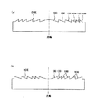
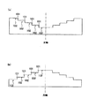
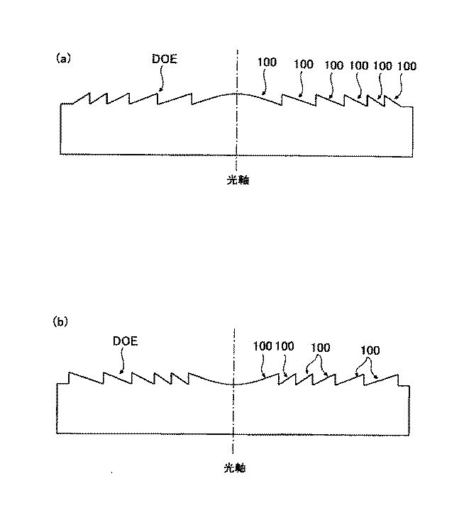
上述の位相構造は、回折構造、光路差付与構造の何れであっても良い。回折構造としては、図1に模式的に示すように、複数の輪帯100から構成され、光軸を含む断面形状が鋸歯形状であるものや、図2に模式的に示すように、段差101の方向が有効径内で同一である複数の輪帯102から構成され、光軸を含む断面形状が階段形状であるものや、図3に模式的に示すように、内部に階段構造が形成された複数の輪帯103から構成されるものや、図4に模式的に示すように、段差104の方向が有効径途中で入れ替わる複数の輪帯105から構成され、光軸を含む断面形状が階段形状であるものがある。また、光路差付与構造としては、図4に模式的に示すように、段差104の方向が有効径途中で入れ替わる複数の輪帯105から構成され、光軸を含む断面形状が階段形状であるものがある。従って、図4に模式的に示した構造は、回折構造である場合もあるし、光路差付与構造である場合もある。尚、図1乃至図4は、各位相構造を平面上に形成した場合を模式的に示したものであるが、各位相構造を球面或いは非球面上に形成しても良い。
The phase structure described above may be either a diffractive structure or an optical path difference providing structure. As schematically shown in FIG. 1, the diffractive structure includes a plurality of
また、本明細書において、「対物光学系」とは、光ピックアップ装置において光ディスクに対向する位置に配置され、光源から射出された波長が互いに異なる光束を、記録密度が互いに異なる光ディスクのそれぞれの情報記録面上に集光する機能を有する集光素子を少なくとも含む光学系を指す。対物光学系は集光素子のみから構成されていても良く、かかる場合には、集光素子の光学面上に位相構造が形成される。 Further, in this specification, the “objective optical system” is an optical pickup device that is arranged at a position facing the optical disk, and emits light beams having different wavelengths emitted from the light source, and information on each of the optical disks having different recording densities. An optical system including at least a condensing element having a function of condensing on a recording surface. The objective optical system may be composed of only the condensing element. In such a case, a phase structure is formed on the optical surface of the condensing element.
更に、上述の集光素子と一体となってアクチュエータによりトラッキング及びフォーカシングを行う光学素子がある場合には、これら光学素子と集光素子とから構成される光学系が対物光学系となる。対物光学系がこのように、複数の光学素子から構成される場合には、集光素子の光学面上に位相構造を形成しても良いが、位相構造の段差部分による光束のけられの影響を低減するためには、集光素子以外の光学素子の光学面上に位相構造を形成するのが好ましい。 Further, when there is an optical element that is integrated with the above-described condensing element and performs tracking and focusing by an actuator, an optical system composed of these optical element and the condensing element is an objective optical system. When the objective optical system is composed of a plurality of optical elements in this way, a phase structure may be formed on the optical surface of the light condensing element. In order to reduce this, it is preferable to form a phase structure on the optical surface of the optical element other than the light condensing element.
また、上述の集光素子は、プラスチックレンズであっても良いし、ガラスレンズであっても良い。集光素子をプラスチックレンズとする場合は、環状オレフィン系のプラスチック材料を使用するのが好ましく、環状オレフィン系の中でも、波長405nmに対する温度25℃での屈折率N405が1.54乃至1.60の範囲内であって、−5℃から70℃の温度範囲内での温度変化に伴う波長405nmに対する屈折率変化率dN405/dT(℃−1)が−10×10−5乃至−8×10−5の範囲内であるプラスチック材料を使用するのがより好ましい。 Moreover, the above-mentioned condensing element may be a plastic lens or a glass lens. When the condensing element is a plastic lens, it is preferable to use a cyclic olefin-based plastic material. Among the cyclic olefin-based materials, the refractive index N 405 at a temperature of 25 ° C. with respect to a wavelength of 405 nm is 1.54 to 1.60. The refractive index change rate dN 405 / dT (° C. −1 ) with respect to a wavelength of 405 nm accompanying a temperature change within a temperature range of −5 ° C. to 70 ° C. is −10 × 10 −5 to −8 ×. It is more preferred to use a plastic material that is in the range of 10 −5 .
また、集光素子をガラスレンズとする場合は、ガラス転移点Tgが400℃以下であるガラス材料を使用すると、比較的低温での成形が可能となるので、金型の寿命を延ばすことが出来る。このようなガラス転移点Tgが低いガラス材料としては、例えば(株)住田光学ガラス製のK−PG325や、K−PG375(共に製品名)がある。 Further, when the condensing element is a glass lens, when a glass material having a glass transition point Tg of 400 ° C. or lower is used, molding at a relatively low temperature is possible, so that the life of the mold can be extended. . Examples of such a glass material having a low glass transition point Tg include K-PG325 and K-PG375 (both product names) manufactured by Sumita Optical Glass Co., Ltd.
ところで、ガラスレンズは一般的にプラスチックレンズよりも比重が大きいため集光素子をガラスレンズとすると、重量が大きくなり対物光学系を駆動するアクチュエータに負担がかかる。そのため、集光素子をガラスレンズとする場合には、比重が小さいガラス材料を使用するのが好ましい。具体的には、比重が3.0以下であるのが好ましく、2.8以下であるのがより好ましい。 By the way, since the specific gravity of the glass lens is generally larger than that of the plastic lens, if the condensing element is made of a glass lens, the weight is increased and a load is imposed on the actuator that drives the objective optical system. Therefore, when the condensing element is a glass lens, it is preferable to use a glass material having a small specific gravity. Specifically, the specific gravity is preferably 3.0 or less, and more preferably 2.8 or less.
また、上述の集光素子の材料として、プラスチック材料中に直径が30nm以下の粒子を分散させた材料を使用しても良い。温度が上昇すると屈折率が下がるプラスチック材料に、温度が上昇すると屈折率が上昇する無機材料を均質に混成することで両者の屈折率の温度依存性を打ち消すことが可能となる。これにより、プラスチック材料の成形性を保持したまま、温度変化に伴う屈折率変化が小さい光学材料(以下、かかる光学材料を「アサーマル樹脂」と呼ぶ)を得ることが出来る。 Further, as a material for the above-described light collecting element, a material in which particles having a diameter of 30 nm or less are dispersed in a plastic material may be used. By uniformly mixing an inorganic material whose refractive index increases as the temperature rises with a plastic material whose refractive index increases as the temperature rises, it becomes possible to cancel the temperature dependence of both refractive indices. Thereby, it is possible to obtain an optical material having a small refractive index change accompanying a temperature change (hereinafter referred to as “athermal resin”) while maintaining the moldability of the plastic material.
ここで、集光素子の屈折率の温度変化について説明する。温度変化に対する屈折率の変化率は、Lorentz−Lorenzの公式に基づいて、屈折率nを温度Tで微分することにより、
以下の数3に示すAで表される。
Here, the temperature change of the refractive index of the condensing element will be described. The rate of change of the refractive index with respect to the temperature change is obtained by differentiating the refractive index n with respect to the temperature T based on the Lorentz-Lorenz formula.
It is represented by A shown in Equation 3 below.
一般的なプラスチック材料の場合は、第1項に比べて第2項の寄与が小さいので第2項はほぼ無視出来る。たとえば、アクリル樹脂(PMMA)の場合、線膨張係数αは7×10⁻⁵である、上式に代入すると、A=−12×10−5となり、実測値と概ね一致する。ここで、アサーマル樹脂では、直径が30nm以下の微粒子プラスチック材料中に分散させることにより、実質的に上式の第2項の寄与を大きくし、第1項の線膨張による変化と打ち消しあうようにさせている。具体的には、従来は−12×10−5程度であった温度変化に対する屈折率変化率を、絶対値で10×10−5未満に抑えることが好ましい。より好ましくは、8×10⁻⁵未満、更に好ましくは、6×10⁻⁵未満に抑えることが、集光素子の温度変化に伴う球面収差変化を低減するうえで好ましい。 In the case of a general plastic material, since the contribution of the second term is smaller than that of the first term, the second term can be almost ignored. For example, in the case of acrylic resin (PMMA), linear expansion coefficient α is 7 × 10 -5, and when substituted into the above equation, A = -12 × 10 -5 holds to agree generally with actual measurements. Here, in the athermal resin, by dispersing in a fine particle plastic material having a diameter of 30 nm or less, the contribution of the second term of the above formula is substantially increased, and the change due to the linear expansion of the first term is canceled out. I am letting. Specifically, it is preferable to suppress the refractive index change rate with respect to temperature change, which was conventionally about −12 × 10 −5 , to an absolute value of less than 10 × 10 −5 . More preferably, it is preferably less than 8 × 10 −5 , and more preferably less than 6 × 10 −5 , in order to reduce the change in spherical aberration associated with the temperature change of the condensing element.
例えば、アクリル樹脂(PMMA)に、酸化ニオブ(Nb2O5)の微粒子を分散させることにより、このような温度変化に対する屈折率変化の依存性を解消することが出来る。母材となるプラスチック材料は、体積比で80、酸化ニオブは20程度の割合であり、これらを均一に混合する。微粒子は凝集しやすいという問題があるが、粒子表面に電荷を与えて分散させる技術も知られており、必要な分散状態を生じさせることが出来る。 For example, by dispersing fine particles of niobium oxide (Nb 2 O 5 ) in acrylic resin (PMMA), the dependency of the refractive index change on the temperature change can be eliminated. The plastic material used as the base material has a volume ratio of 80 and niobium oxide in a ratio of about 20, and these are uniformly mixed. There is a problem that the fine particles are likely to aggregate, but a technique for imparting electric charges to the particle surface to disperse the particles is also known, and a necessary dispersion state can be generated.
尚、この体積比率は、温度変化に対する屈折率の変化の割合をコントロールするために、適宜増減できるし、複数種類のナノサイズ無機粒子をブレンドして分散させることも可能である。 This volume ratio can be appropriately increased or decreased in order to control the rate of change in refractive index with respect to temperature change, and a plurality of types of nano-sized inorganic particles can be blended and dispersed.
体積比率では、上記の例では80:20であるが、90:10〜60:40までの間で適宜調整可能である。90:10よりも体積比率が小さいと屈折率変化抑制の効果が小さくなり、逆に、60:40を超えるとアサーマル樹脂の成形性に問題が生じるために好ましくない。 The volume ratio is 80:20 in the above example, but can be appropriately adjusted between 90:10 and 60:40. If the volume ratio is smaller than 90:10, the effect of suppressing the change in refractive index is reduced. Conversely, if the volume ratio exceeds 60:40, a problem occurs in the moldability of the athermal resin, which is not preferable.
微粒子は無機物であることが好ましく、更に、酸化物であることが好ましい。そして酸化状態が飽和していて、それ以上酸化しない酸化物であることが好ましい。無機物であることは、高分子有機化合物であるプラスチック材料との反応を低く抑えるために好ましく、また酸化物であることによって、青紫色レーザの長時間の照射に伴う透過率劣化や波面収差劣化を防ぐことが出来る。特に、高温下において青紫色レーザが照射されるという過酷な条件において、酸化が促進されやすくなるが、このような無機酸化物であれば、酸化による透過率劣化や波面収差劣化を防ぐことが出来る。 The fine particles are preferably inorganic and more preferably oxides. And it is preferable that it is an oxide which the oxidation state is saturated and does not oxidize any more. It is preferable to be an inorganic substance in order to keep the reaction with a plastic material which is a high molecular organic compound low, and because it is an oxide, it deteriorates transmittance and wavefront aberration due to long-term irradiation of a blue-violet laser. Can be prevented. In particular, oxidation is likely to be accelerated under the severe condition of being irradiated with a blue-violet laser at a high temperature. However, with such an inorganic oxide, it is possible to prevent transmittance deterioration and wavefront aberration deterioration due to oxidation. .
尚、プラスチック材料に分散させる微粒子の直径が大きいと、入射光束の散乱が生じやすくなり集光素子の透過率が低下する。高密度光ディスクにおいて、情報の記録/再生に使用される青紫色レーザの出力が十分高くない現状においては、集光素子の青紫色レーザ光束に対する透過率が低いと、記録速度の高速化、多層ディスク対応という観点で不利となる。従って、プラスチック材料に分散させる微粒子の直径は、好ましくは20nm以下、更に好ましくは10〜15nm以下であることが集光素子の透過率低下を防ぐ上で好ましい。 When the diameter of the fine particles dispersed in the plastic material is large, the incident light beam is easily scattered and the transmittance of the condensing element is lowered. In a high-density optical disc, the output of a blue-violet laser used for recording / reproducing information is not sufficiently high. If the transmittance of the condensing element to the blue-violet laser beam is low, the recording speed is increased, and the multilayer disc It is disadvantageous in terms of response. Accordingly, the diameter of the fine particles dispersed in the plastic material is preferably 20 nm or less, and more preferably 10 to 15 nm or less in order to prevent a decrease in the transmittance of the light collecting element.
請求項2に記載の光ピックアップ装置は、請求項1に記載の発明において、前記位相構造は、回折構造であることを特徴とする。本発明のように、前記位相構造として回折構造を利用することで、記録密度が互いに異なる3種類の光ディスク用互換対物光学系の特性をより向上させることが可能となる。 According to a second aspect of the present invention, in the invention according to the first aspect, the phase structure is a diffractive structure. By using a diffraction structure as the phase structure as in the present invention, it is possible to further improve the characteristics of three types of compatible objective optical systems for optical discs having different recording densities.
請求項3に記載の光ピックアップ装置は、請求項1又は2に記載の発明において、前記コリメートレンズは、前記対物光学系の光源側、かつ前記第1光束、前記第2光束、前記第3光束が通過する共通光路内に配置されることを特徴とする。本発明のように、前記コリメートレンズを、対物光学系の光源側であって、かつ前記第1光束、前記第2光束、前記第3光束が通過する共通光路内に配置させることで、前記第1光束用の光学部品と、前記第2光束用の光学部品、前記第3光束用の光学部品とを共通化することが出来るので、光ピックアップ装置の部品点数の削減、構成の簡略化が可能となり、その結果、光ピックアップ装置の製造コストを低減出来る。 According to a third aspect of the present invention, there is provided the optical pickup device according to the first or second aspect, wherein the collimating lens includes a light source side of the objective optical system, the first light beam, the second light beam, and the third light beam. Is arranged in a common optical path through which the light passes. As in the present invention, the collimating lens is disposed on the light source side of the objective optical system and in a common optical path through which the first light flux, the second light flux, and the third light flux pass, so that the first Since the optical component for one beam, the optical component for the second beam, and the optical component for the third beam can be shared, the number of components of the optical pickup device can be reduced and the configuration can be simplified. As a result, the manufacturing cost of the optical pickup device can be reduced.
請求項4に記載の光ピックアップ装置は、請求項1〜3のいずれかに記載の発明において、前記コリメートレンズは以下の条件を満たすことを特徴とする請求項1から3のいずれかに記載の光ピックアップ装置。
0.01 < ΔCL/fCL <0.05 (1)
ΔCL:前記コリメートレンズ移動量
fCL:前記コリメートレンズの第1光源波長に対する焦点距離
The optical pickup device according to claim 4 is the optical pickup device according to any one of claims 1 to 3, wherein the collimating lens satisfies the following condition. Optical pickup device.
0.01 <ΔCL / fCL <0.05 (1)
ΔCL: movement amount of the collimating lens fCL: focal length of the collimating lens with respect to the first light source wavelength
前記コリメートレンズが(1)式を満たすことで、前記対物光学系を、前記第1倍率M1、前記第2倍率M2、前記第3倍率M3が同じ倍率(0)となるようにして用いることが可能となる。上記値が(1)式の上下限を越えると、例えば前記第1光束用のコリメートレンズと前記第2光束用のコリメートレンズとを共通化した場合、これら共通の光学部品を透過して、前記対物光学系に入射する前記第1光束と前記第2光束の発散度合いが、上述した共通光学部品の色収差の影響で互いに異なってしまうので好ましくない。なぜなら、(1)式を満たさない前記対物光学系に対して、発散度合いが互いに異なる前記第1光束及び前記第2光束が入射すると、何れかの光束に対して球面収差が発生する恐れがあるからである。 When the collimating lens satisfies the expression (1), the objective optical system is used such that the first magnification M1, the second magnification M2, and the third magnification M3 are the same magnification (0). It becomes possible. When the above value exceeds the upper and lower limits of the expression (1), for example, when the collimating lens for the first light beam and the collimating lens for the second light beam are shared, the light passes through these common optical components, and The degree of divergence of the first light beam and the second light beam incident on the objective optical system is not preferable because they are different from each other due to the chromatic aberration of the common optical component. This is because if the first light beam and the second light beam having different degrees of divergence are incident on the objective optical system that does not satisfy the expression (1), spherical aberration may occur for any light beam. Because.
但し、(1)式に規定する条件の範囲を超えた場合でも、前記第1光束と前記第2光束の共通の光路中に、上述した共通光学部品の色収差を補正する機能を有する色収差補正素子を配置することで、前記対物光学系に入射する前記第1光束と、前記対物光学系に入射する前記第2光束の発散度合いを同じにすることができる。かかる色収差補正素子としては、波長分散が互いに異なる正レンズと負レンズとから構成されるダブレットレンズであっても良いし、回折光学素子であっても良い。またこれら色収差補正素子は、上述した共通光学部品と別体であっても構わないし、共通光学部品内に設けることも可能である。しかしながら、このような色収差補正素子を用いると部品点数が増加したり加工が困難になったりして、装置の複雑化とコストアップを招いてしまう。装置の簡素化、低コスト化という観点からは、それらを用いずに構成することが望ましいといえる。 However, a chromatic aberration correcting element having a function of correcting the chromatic aberration of the above-mentioned common optical component in the common optical path of the first light flux and the second light flux even when the range of the condition defined in the expression (1) is exceeded. By arranging the above, the divergence degree of the first light beam incident on the objective optical system and the second light beam incident on the objective optical system can be made the same. Such a chromatic aberration correcting element may be a doublet lens composed of a positive lens and a negative lens having different wavelength dispersion, or a diffractive optical element. These chromatic aberration correction elements may be separate from the above-described common optical component or may be provided in the common optical component. However, when such a chromatic aberration correcting element is used, the number of parts increases and processing becomes difficult, resulting in an increase in complexity and cost of the apparatus. From the viewpoint of simplifying the apparatus and reducing the cost, it can be said that it is desirable to configure without using them.
請求項5に記載の光ピックアップ装置は、請求項1〜4のいずれかに記載の発明において、前記第1光源、前記第2光源、前記第3光源の3つの光源の内、少なくとも2つは一体化されていることを特徴とする。本発明のように、複数光源が一体化された光源ユニットを使用することで、光ピックアップ装置の構成の更なる簡略化が可能となる。ここで、複数光源が一体化された光源ユニットは、例えば前記第1光束を発生する発光部と、前記第2光束を発生する発光部を同一の基板上に形成した光源ユニットであっても良いし、例えば前記第1光束を発生する半導体チップと、前記第2光束を発生する半導体チップとを1つの筐体内に納めた光源ユニットであっても良い。ここで、前記第1光源から前記第3光源まで全ての光源が一体化された光源ユニットであると、更に部品点数を削減することが可能となり、装置の小型化に有利となり望ましい。また、前記第1光源から前記第3光源までの内、2つの光源を一体化した光源ユニットとした場合、残り1つの光源に関しては、光源と前記光源光束用の光検出器とが一体化された光源ユニットを使用すると、装置が簡素化され小型化に有利であるので望ましい。 According to a fifth aspect of the present invention, in the invention according to any one of the first to fourth aspects, at least two of the first light source, the second light source, and the third light source are at least two. It is characterized by being integrated. As in the present invention, by using a light source unit in which a plurality of light sources are integrated, the configuration of the optical pickup device can be further simplified. Here, the light source unit in which a plurality of light sources are integrated may be, for example, a light source unit in which a light emitting unit that generates the first light beam and a light emitting unit that generates the second light beam are formed on the same substrate. For example, it may be a light source unit in which a semiconductor chip that generates the first light flux and a semiconductor chip that generates the second light flux are housed in one housing. Here, it is desirable that the light source unit in which all the light sources from the first light source to the third light source are integrated can further reduce the number of parts, which is advantageous for downsizing of the apparatus. Further, when the light source unit is formed by integrating two light sources from the first light source to the third light source, for the remaining one light source, the light source and the light source light detector are integrated. The use of a light source unit is desirable because it simplifies the apparatus and is advantageous for miniaturization.
請求項6に記載の光ピックアップ装置は、第1波長λ1の第1光束を射出する第1光源と、第2波長λ2(λ2>λ1)の第2光束を射出する第2光源と、第3波長λ3(λ3>λ2)の第3光束を射出する第3光源と、前記第1光束を記録密度ρ1の第1光情報記録媒体の情報記録面上に集光させ、前記第2光束を記録密度ρ2(ρ2<ρ1)の第2光情報記録媒体の情報記録面上に集光させ、前記第3光束を記録密度ρ3(ρ3<ρ2)の第3光情報記録媒体の情報記録面上に集光させるための対物光学系と、を有し、前記光源からの光束を前記対物光学系を介して前記光情報記録媒体の情報記録面に集光させることによって情報の記録及び/又は再生を行う光ピックアップ装置において、
前記対物光学系は位相構造を有し、前記第1光情報記録媒体に対して情報の記録及び/又は再生を行う際の前記対物光学系の倍率を第1倍率M1、前記第2光情報記録媒体に対して情報の記録及び/又は再生を行う際の前記対物光学系の倍率を第2倍率M2、前記第3光情報記録媒体に対して情報の記録及び/又は再生を行う際の前記対物光学系の倍率を第3倍率M3とした時、M1=M2=M3=0を満たすとともに、
前記それぞれの光源からの光束を平行光束または略平行光束として前記対物光学系に光束を入射させるためのコリメートレンズと、収差補正を行うための収差補正手段とを有し、前記収差補正手段が少なくとも2枚のレンズで構成されるとともに、少なくとも1枚の前記レンズは光軸と平行な方向に移動可能であることを特徴とする。
The optical pickup device according to claim 6 is a first light source that emits a first light beam having a first wavelength λ1, a second light source that emits a second light beam having a second wavelength λ2 (λ2> λ1), and a third light source. A third light source that emits a third light beam having a wavelength λ3 (λ3> λ2), and the first light beam is condensed on an information recording surface of a first optical information recording medium having a recording density ρ1, and the second light beam is recorded. The third light beam is condensed on the information recording surface of the second optical information recording medium having the density ρ2 (ρ2 <ρ1), and the third light beam is focused on the information recording surface of the third optical information recording medium having the recording density ρ3 (ρ3 <ρ2). An objective optical system for condensing, and recording and / or reproducing information by condensing the light beam from the light source on the information recording surface of the optical information recording medium via the objective optical system. In the optical pickup device to perform,
The objective optical system has a phase structure, and the magnification of the objective optical system when recording and / or reproducing information with respect to the first optical information recording medium is a first magnification M1, and the second optical information recording is performed. A magnification of the objective optical system when recording and / or reproducing information on the medium is a second magnification M2, and the objective when recording and / or reproducing information on the third optical information recording medium. When the magnification of the optical system is the third magnification M3, M1 = M2 = M3 = 0 is satisfied,
A collimating lens for causing the light beam from each of the light sources to enter the objective optical system as a parallel light beam or a substantially parallel light beam, and an aberration correction unit for performing aberration correction, wherein the aberration correction unit is at least It is composed of two lenses, and at least one of the lenses is movable in a direction parallel to the optical axis.
本発明によれば、前記、第1光束乃至第3光束に対するそれぞれの前記対物光学系の第1倍率M1乃至第3倍率M3をM1=M2=M3=0(ここでの倍率=0とは、厳密にいえば平行光束が入射することをいうが、略平行光束が入射する場合を含む)とすることで、トラッキングによるレンズシフトが発生しても、収差の劣化が起こらないようにすることができる。 According to the present invention, the first magnification M1 to the third magnification M3 of the objective optical system with respect to the first light flux to the third light flux are set to M1 = M2 = M3 = 0 (here, magnification = 0) Strictly speaking, it means that a parallel light beam is incident, but includes a case where a substantially parallel light beam is incident), so that aberrations do not deteriorate even if a lens shift occurs due to tracking. it can.
しかしながら、その場合において、それぞれの光源からの光束に共通のコリメートレンズを用いて対物光学系に入射する光束を平行又は略平行(ここでの略平行とは光軸と光束のマージナル光が成す角度が±1度以内の状態をいうものとする)とすると、それぞれの光ディスクに対して情報の記録及び/又は再生を行うための光源波長が異なることから、コリメートレンズの持つ色収差によって第1光源乃至第3光源それぞれについてコリメートレンズから光源までの望ましい距離が異なってしまい、それらの内2つの光源を一体化したり、3つの光源を全て一体化したような構成にすることが出来ないという問題が発生してしまう。又は、2つの光源を一体化したり、3つの光源を全て一体化したような構成にすると、コリメートレンズの色収差によって発生する対物光学系の収差が問題となり、そのままの構成では問題が発生してしまう。 However, in that case, the light beam incident on the objective optical system is made parallel or substantially parallel by using a common collimating lens for the light beams from the respective light sources (here, the substantially parallel is the angle formed by the optical axis and the marginal light of the light beam) Is within ± 1 degree), the light source wavelengths for recording and / or reproducing information on the respective optical discs are different. The desired distance from the collimating lens to the light source differs for each of the third light sources, and there is a problem that it is not possible to integrate two of these light sources or to have a configuration in which all three light sources are integrated. Resulting in. Or, if two light sources are integrated, or if all three light sources are integrated, the aberration of the objective optical system caused by the chromatic aberration of the collimating lens becomes a problem, and the problem will occur if the configuration is unchanged. .
これに対し、本発明においては、収差補正を行うための収差補正手段を設けており、前記収差補正手段が、少なくとも1枚のレンズが光軸と平行な方向に移動可能である2枚以上のレンズを有しているので、所与の位置に前記少なくとも1枚のレンズを移動させることによって収差補正を行えるため、前記コリメートレンズと光源との間の距離を変えることなく波長の異なる3つの光源の内2つの光源を一体化したり、3つの光源を全て一体化したような構成を実現することが可能となる。また前記第1光束乃至第3光束に対するそれぞれの対物光学系の第1倍率M1乃至第3倍率M3をM1=M2=M3=0として使用することが望ましいことから、前記収差補正手段を前記コリメートレンズの対物光学系側に配置して、少なくとも1枚の負レンズと少なくとも1枚の正レンズ、の2つのレンズで構成してもよい。それにより前記コリメートレンズからの平行又は略平行光束を、そのまま平行又は略平行光束として前記対物光学系に入射させることが可能となる。また前記収差補正手段が負レンズを用いていることから、色収差の補正も有利となる。また、前記コリメートレンズを共通化したり、前記光源を一体化させることで、光ピックアップ装置の構成が簡素化され、装置の小型化や低コスト化が達成されるので望ましい。 On the other hand, in the present invention, aberration correction means for correcting aberration is provided, and the aberration correction means includes at least two lenses in which at least one lens is movable in a direction parallel to the optical axis. Since it has a lens, aberration correction can be performed by moving the at least one lens to a given position, so that three light sources having different wavelengths can be obtained without changing the distance between the collimating lens and the light source. It is possible to realize a configuration in which two light sources are integrated or all three light sources are integrated. Further, since it is desirable to use the first magnification M1 to the third magnification M3 of each objective optical system for the first light flux to the third light flux as M1 = M2 = M3 = 0, the aberration correction means is used as the collimating lens. It may be arranged on the objective optical system side, and may be constituted by two lenses, at least one negative lens and at least one positive lens. Thereby, the parallel or substantially parallel light beam from the collimating lens can be directly incident on the objective optical system as a parallel or substantially parallel light beam. Further, since the aberration correction means uses a negative lens, correction of chromatic aberration is also advantageous. Further, it is desirable that the collimating lens is made common or the light source is integrated, thereby simplifying the configuration of the optical pickup device and achieving downsizing and cost reduction of the device.
尚、請求項6に記載の光ピックアップ装置において、請求項1に記載の発明と同様の構成に関しては、同様の作用効果を奏するため、その説明を省略する。 Note that in the optical pickup device according to the sixth aspect, the same configuration as that of the first aspect of the invention has the same function and effect, and thus the description thereof is omitted.
請求項7に記載の光ピックアップ装置は、請求項6に記載の発明において、前記位相構造は、回折構造であることを特徴とする。本発明のように、位相構造として回折構造を利用することで、記録密度が互いに異なる3種類の光ディスク用互換対物光学系の特性をより向上させることが可能となる。 According to a seventh aspect of the present invention, in the invention according to the sixth aspect, the phase structure is a diffractive structure. By using a diffractive structure as a phase structure as in the present invention, it is possible to further improve the characteristics of three types of compatible objective optical systems for optical discs having different recording densities.
請求項8に記載の光ピックアップ装置は、請求項6又は7に記載の発明において、前記収差補正手段は、球面収差補正を行うことを特徴とする。本発明のように、前記収差補正手段が球面収差を補正するので、前記第1光情報記録媒体及至前記第3光情報記録媒体の情報の記録/再生を行うに際して、前記対物光学系の前記第1倍率及至前記第3倍率をM1=M2=M3=0としながら1つのコリメートレンズとして構成した場合に生じる波長変化による球面収差を補正することが可能となるので、結果として単一のコリメートレンズを有する光ピックアップ装置が構成され、装置の簡素化や小型化、低コスト化が達成できるので望ましい。 An optical pickup apparatus according to an eighth aspect of the invention is characterized in that, in the invention according to the sixth or seventh aspect, the aberration correction means performs spherical aberration correction. As in the present invention, since the aberration correction means corrects spherical aberration, when recording / reproducing information on the first optical information recording medium and the third optical information recording medium, the first optical information recording medium is recorded. Since it is possible to correct the spherical aberration caused by the wavelength change when it is configured as one collimating lens while M1 = M2 = M3 = 0 while setting the first magnification to the third magnification, a single collimating lens can be obtained as a result. This is desirable because an optical pickup device having the above configuration is achieved, and the device can be simplified, downsized, and reduced in cost.
請求項9に記載の光ピックアップ装置は、請求項6〜8のいずれかに記載の発明において、前記収差補正手段は、前記対物光学系の光源側、かつ、前記コリメートレンズの対物光学系側で、前記第1光束、前記第2光束、前記第3光束が通過する共通光路内に配置されることを特徴とする。本発明のように、前記収差補正手段を、前記対物光学系の光源側であって、かつ前記コリメートレンズの対物光学系側の前記第1光束、前記第2光束、前記第3光束の共通光路内に配置させることで、前記第1光束用の光学部品と、前記第2光束用の光学部品、前記第3光束用の光学部品とを共通化することが出来るので、光ピックアップ装置の部品点数の削減、構成の簡略化が可能となり、その結果、光ピックアップ装置の製造コストを低減出来る。 An optical pickup device according to a ninth aspect is the invention according to any one of the sixth to eighth aspects, wherein the aberration correction unit is provided on a light source side of the objective optical system and on an objective optical system side of the collimating lens. The first light beam, the second light beam, and the third light beam are disposed in a common optical path through which the first light beam, the second light beam, and the third light beam pass. As in the present invention, the aberration correcting means is a common optical path of the first light flux, the second light flux, and the third light flux on the light source side of the objective optical system and on the objective optical system side of the collimating lens. By arranging the optical component for the first light flux, the optical component for the second light flux, the optical component for the third light flux, and the optical component for the third light flux can be shared, so that the number of parts of the optical pickup device Can be reduced and the configuration can be simplified. As a result, the manufacturing cost of the optical pickup device can be reduced.
請求項10に記載の光ピックアップ装置は、請求項6〜9のいずれかに記載の発明において、前記収差補正手段は、1枚のレンズのみを移動させることを特徴とする。本発明のように、前記収差補正手段が1枚のレンズのみを移動させる構成であるので、最も少ない移動レンズで収差の補正が可能になることからレンズ移動のための機構が簡素化され、装置の小型化や低コスト化に効果がある。 According to a tenth aspect of the present invention, in the invention according to any one of the sixth to ninth aspects, the aberration correction unit moves only one lens. Since the aberration correction means moves only one lens as in the present invention, aberration correction can be performed with the least number of moving lenses, so the mechanism for moving the lens is simplified, and the apparatus This is effective for downsizing and cost reduction.
請求項11に記載の光ピックアップ装置は、請求項6〜10のいずれかに記載の発明において、前記収差補正手段は以下の条件を満たすことを特徴とする。
0.001 < |ΔML/fBEML| <0.02 (2)
ΔBEML:前記収差補正手段における移動するレンズの移動量
fBEML:前記収差補正手段における移動するレンズの第1光源波長に対する焦点距離
An optical pickup device according to an eleventh aspect is characterized in that, in the invention according to any one of the sixth to tenth aspects, the aberration correcting means satisfies the following condition.
0.001 <| ΔML / fBEML | <0.02 (2)
ΔBEML: Amount of movement of the moving lens in the aberration correction unit fBEML: Focal length of the moving lens in the aberration correction unit with respect to the first light source wavelength
前記収差補正手段が(2)式を満たすことで、前記対物光学系を、前記第1倍率M1、前記第2倍率M2、前記第3倍率M3が同じ倍率(0)となるようにして用いることが可能となる。上記値が(2)式の上下限を越えると、例えば前記第1光束用のコリメートレンズと、前記第2光束用のコリメートレンズとを共通化した場合、これら共通の光学部品を透過して、前記対物光学系に入射する前記第1光束と前記第2光束の発散度合いが、上述した共通光学部品の色収差の影響で互いに異なってしまうので好ましくない。なぜなら、(2)式を満たさない前記対物光学系に対して、発散度合いが互いに異なる前記第1光束及び前記第2光束が入射すると、何れかの光束に対して球面収差が発生する恐れがあるからである。 When the aberration correction unit satisfies the expression (2), the objective optical system is used such that the first magnification M1, the second magnification M2, and the third magnification M3 are the same magnification (0). Is possible. When the above value exceeds the upper and lower limits of the expression (2), for example, when the collimating lens for the first light beam and the collimating lens for the second light beam are shared, the light passes through these common optical components, The degree of divergence of the first light beam and the second light beam incident on the objective optical system is not preferable because they are different from each other due to the chromatic aberration of the common optical component. This is because, when the first light beam and the second light beam having different divergence degrees are incident on the objective optical system that does not satisfy the expression (2), spherical aberration may occur for any of the light beams. Because.
但し、(2)式に規定する条件の範囲を超えた場合でも、前記第1光束と前記第2光束の共通の光路中に、上述した共通光学部品の色収差を補正する機能を有する色収差補正素子を配置することで、前記対物光学系に入射する前記第1光束と、前記対物光学系に入射する前記第2光束の発散度合いを同じにすることが可能となる。かかる色収差補正素子としては、波長分散が互いに異なる正レンズと負レンズとから構成されるダブレットレンズであっても良いし、回折光学素子であっても良い。またこれら色収差補正素子は、上述したコリメートレンズや収差補正素子等の共通光学部品と別体であっても構わないし、共通光学部品内に設けることも可能である。しかしながら、このような色収差補正素子を用いると部品点数が増加したり加工が困難になったりして、装置の複雑化とコストアップを招いてしまう。装置の簡素化、低コスト化という観点からは、それらを用いずに構成することが望ましいといえる。 However, a chromatic aberration correcting element having a function of correcting the chromatic aberration of the above-mentioned common optical component in the common optical path of the first light flux and the second light flux even when the range of the condition defined in the expression (2) is exceeded. It is possible to make the degree of divergence of the first light beam incident on the objective optical system and the second light beam incident on the objective optical system the same. Such a chromatic aberration correcting element may be a doublet lens composed of a positive lens and a negative lens having different wavelength dispersion, or a diffractive optical element. These chromatic aberration correction elements may be separate from the common optical parts such as the collimating lens and the aberration correction element described above, or may be provided in the common optical parts. However, when such a chromatic aberration correcting element is used, the number of parts increases and processing becomes difficult, resulting in an increase in complexity and cost of the apparatus. From the viewpoint of simplifying the apparatus and reducing the cost, it can be said that it is desirable to configure without using them.
請求項12に記載の光ピックアップ装置は、請求項6〜11のいずれかに記載の発明において、前記第1光源、前記第2光源、前記第3光源の3つの光源の内、少なくとも2つは一体化されていることを特徴とする。本発明のように、複数光源が一体化された光源ユニットを使用することで、光ピックアップ装置の構成の更なる簡略化が可能となる。ここで、複数光源が一体化された光源ユニットは、例えば第1光束を発生する発光部と第2光束を発生する発光部、又は第2光束を発生する発光部と第3光束を発生する発光部を同一の基板上に形成した光源ユニットであっても良いし、例えば第1光束を発生する半導体チップと第2光束を発生する半導体チップ、又は第2光束を発生する半導体チップと第3光束を発生する半導体チップとを1つの筐体内に納めた光源ユニットであっても良い。ここで、前記第1光源から前記第3光源まで全ての光源が一体化された光源ユニットであると、更に部品点数を削減することが可能となり、装置の小型化に有利となり望ましい。また、前記第1光源から前記第3光源までの内、2つの光源を一体化した光源ユニットとした場合、残り1つの光源に関しては、光源と前記光源光束用の光検出器とが一体化された光源ユニットを使用すると、装置が簡素化され小型化に有利であるので望ましい。 An optical pickup device according to a twelfth aspect is the invention according to any one of the sixth to eleventh aspects, wherein at least two of the three light sources of the first light source, the second light source, and the third light source are It is characterized by being integrated. As in the present invention, by using a light source unit in which a plurality of light sources are integrated, the configuration of the optical pickup device can be further simplified. Here, the light source unit in which a plurality of light sources are integrated is, for example, a light emitting unit that generates a first light beam and a light emitting unit that generates a second light beam, or a light emitting unit that generates a second light beam and light emission that generates a third light beam. The light source unit may be formed on the same substrate. For example, the semiconductor chip that generates the first light beam and the semiconductor chip that generates the second light beam, or the semiconductor chip that generates the second light beam and the third light beam. It may be a light source unit in which a semiconductor chip that generates the light is contained in one housing. Here, it is desirable that the light source unit in which all the light sources from the first light source to the third light source are integrated can further reduce the number of parts, which is advantageous for downsizing of the apparatus. Further, when the light source unit is formed by integrating two light sources from the first light source to the third light source, for the remaining one light source, the light source and the light source light detector are integrated. The use of a light source unit is desirable because it simplifies the apparatus and is advantageous for miniaturization.
本発明によれば、位相構造を有し、青紫色レーザ光源を使用する高密度光ディスクとDVDとCDを含む、記録密度が異なる3種類のディスクに対して情報の記録及び/又は再生を適切に行うことができる対物光学系を搭載した光ピックアップ装置であって、その構成の簡素化、低コスト化を実現可能な光ピックアップ装置及び光情報記録再生装置を得ることができる。 According to the present invention, information recording and / or reproduction is appropriately performed on three types of discs having different recording densities, including high-density optical discs having a phase structure and using a blue-violet laser light source, and DVDs and CDs. It is possible to obtain an optical pickup apparatus and an optical information recording / reproducing apparatus that are capable of performing an objective optical system and that can achieve a simplified configuration and a reduced cost.
本発明を実施するための最良の形態について、図面を参照しつつ説明する。 The best mode for carrying out the present invention will be described with reference to the drawings.
[第1の実施の形態]
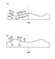
図5は、高密度光ディスクHD(第1光ディスク)とDVD(第2光ディスク)とCD(第3光ディスク)との何れに対しても、簡略な構成で適切に情報の記録/再生を行える第1の光ピックアップ装置PU1の構成を概略的に示す図である。高密度光ディスクHDの光学的仕様は、第1波長λ1=408nm、第1保護層PL1の厚さt1=0.1mm、開口数NA1=0.85であり、DVDの光学的仕様は、第2波長λ2=658nm、第2保護層PL2の厚さt2=0.6mm、開口数NA2=0.60であり、CDの光学的仕様は、第3波長λ3=785nm、第3保護層PL3の厚さt3=1.2mm、開口数NA3=0.45である。
[First Embodiment]
FIG. 5 shows a first example in which information can be appropriately recorded / reproduced with a simple configuration for any of a high-density optical disc HD (first optical disc), DVD (second optical disc), and CD (third optical disc). It is a figure which shows schematically the structure of this optical pick-up apparatus PU1. The optical specifications of the high-density optical disc HD are the first wavelength λ1 = 408 nm, the thickness t1 of the first protective layer PL1 is 0.1 mm, and the numerical aperture NA1 = 0.85. The optical specification of the DVD is the second The wavelength λ2 = 658 nm, the thickness t2 of the second protective layer PL2 = 0.6 mm, the numerical aperture NA2 = 0.60, and the optical specifications of the CD are the third wavelength λ3 = 785 nm and the thickness of the third protective layer PL3. The length t3 = 1.2 mm and the numerical aperture NA3 = 0.45.
第1光ディスク〜第3光ディスクの記録密度(ρ1〜ρ3)は、ρ3<ρ2<ρ1となっており、第1光ディスク〜第3光ディスクに対して情報の記録及び/又は再生を行う際の、対物光学系OBJの倍率(第1倍率M1〜第3倍率M3)は、M1=M2=M3=0となっている。但し、波長、保護層の厚さ、開口数、記録密度及び倍率の組合せはこれに限られない。 The recording densities (ρ1 to ρ3) of the first optical disc to the third optical disc are ρ3 <ρ2 <ρ1, and the objective when recording and / or reproducing information on the first optical disc to the third optical disc is set. The magnification (first magnification M1 to third magnification M3) of the optical system OBJ is M1 = M2 = M3 = 0. However, the combination of wavelength, protective layer thickness, numerical aperture, recording density, and magnification is not limited to this.
光ピックアップ装置PU1は、高密度光ディスクHDに対して情報の記録/再生を行う場合に発光され408nmのレーザ光束(第1光束)を射出する第1の発光部EP1(第1光源)と、DVDに対して情報の記録/再生を行う場合に発光され658nmのレーザ光束(第2光束)を射出する第2の発光部EP2(第2光源)とを同一パッケージ内に収容した(一体化された)2レーザ1パッケージ2L1Pと、CDに対して情報の記録/再生を行う場合に発光され785nmのレーザ光束(第3光束)を射出する赤外半導体レーザLD3(第3光源)と光検出器PD3とが一体化されたホログラムレーザHLと、その光学面上に位相構造としての回折構造が形成された収差補正素子L1とこの収差補正素子L1を透過したレーザ光束を情報記録面RL1、RL2,RL3上に集光させる機能を有する両面が非球面とされた集光素子L2とから構成された対物光学系OBJ、開口制限素子AP、2軸アクチュエータAC1、1軸アクチュエータAC2、高密度光ディスクHDの開口数NA1に対応した絞りSTO、ダイクロイックプリズムDPS、コリメートレンズCOL(可動素子)、カップリングレンズCUL、ビーム整形素子SHとから構成されている。 The optical pickup device PU1 includes a first light emitting unit EP1 (first light source) that emits a 408 nm laser light beam (first light beam) when information is recorded / reproduced with respect to the high-density optical disk HD, and a DVD. And a second light emitting unit EP2 (second light source) that emits a laser beam (second beam) of 658 nm emitted when recording / reproducing information is accommodated in the same package (integrated) 2 Laser 1 package 2L1P, an infrared semiconductor laser LD3 (third light source) emitting a 785 nm laser beam (third beam) when recording / reproducing information on a CD, and a photodetector PD3 Are integrated into a hologram laser HL, an aberration correction element L1 having a diffraction structure as a phase structure on its optical surface, and a laser beam transmitted through the aberration correction element L1. Objective optical system OBJ, aperture limiting element AP, biaxial actuator AC1, monoaxial actuator AC2 including condensing element L2 having both surfaces aspherical and having a function of condensing on recording surfaces RL1, RL2, and RL3 The aperture STO corresponding to the numerical aperture NA1 of the high-density optical disk HD, a dichroic prism DPS, a collimating lens COL (movable element), a coupling lens CUL, and a beam shaping element SH.
光ピックアップ装置PU1において、高密度光ディスクHDに対して情報の記録/再生を行う場合には、2レーザ1パッケージ2L1Pを作動させて第1の発光部EP1を発光させる。第1の発光部EP1から射出された発散光束は、図5において実線でその光線経路を描いたように、ビーム整形素子SHを透過することにより、その断面形状が楕円形から円形に整形され、ダイクロイックプリズムDPSを透過し、コリメートレンズCOLを経て平行光束とされた後、絞りSTOにより光束径が規制され、開口制限素子APを透過し、対物光学系OBJによって第1保護層PL1を介して情報記録面RL1上に形成されるスポットとなる。対物光学系OBJは、その周辺に配置された2軸アクチュエータAC1によってフォーカシングやトラッキングを行う。情報記録面RL1で情報ピットにより変調された反射光束は、再び対物光学系OBJ、開口制限素子APを透過し、コリメートレンズCOLによって収斂光束とされ、ダイクロイックプリズムDPS、ビーム整形素子BSを透過した後、2レーザ1パッケージ2L1P内又はその近傍に配置された光検出器(不図示)で受光される。かかる光検出器の出力信号を用いて、高密度光ディスクHDに記録された情報を読み取ることができる。 When recording / reproducing information with respect to the high-density optical disc HD in the optical pickup device PU1, the two laser 1 package 2L1P is operated to cause the first light emitting unit EP1 to emit light. The divergent light beam emitted from the first light emitting unit EP1 passes through the beam shaping element SH as illustrated by the solid line in FIG. 5, so that its cross-sectional shape is shaped from an ellipse to a circle, The light beam passes through the dichroic prism DPS and is converted into a parallel light beam through the collimating lens COL. Then, the light beam diameter is restricted by the stop STO, the light passes through the aperture limiting element AP, and is passed through the first protective layer PL1 by the objective optical system OBJ. This is a spot formed on the recording surface RL1. The objective optical system OBJ performs focusing and tracking by a biaxial actuator AC1 disposed around the objective optical system OBJ. The reflected light beam modulated by the information pits on the information recording surface RL1 is transmitted again through the objective optical system OBJ and the aperture limiting element AP, is converted into a convergent light beam by the collimating lens COL, and is transmitted through the dichroic prism DPS and the beam shaping element BS. Two lasers are received by a photodetector (not shown) arranged in or near the one package 2L1P. Information recorded on the high-density optical disk HD can be read using the output signal of the photodetector.
また、光ピックアップ装置PU1においてDVDに対して情報の記録/再生を行う場合には、第2光束が平行光束の状態でコリメートレンズCOLから射出されるように、対物光学系OBJとコリメートレンズCOLとの間の距離が、高密度光ディスクHDに対して情報の記録/再生を行う場合よりも小さくなるように1軸アクチュエータAC2によりコリメートレンズCOLを移動させる。その後、2レーザ1パッケージ2L1Pを作動させて第2の発光部EP2を発光させる。但し、前記第2の発光部EP2を発光させた後、最適位置を探索しながらコリメートレンズCOLを移動させても良い。 Further, when recording / reproducing information with respect to the DVD in the optical pickup device PU1, the objective optical system OBJ and the collimating lens COL are arranged so that the second light beam is emitted from the collimating lens COL in the state of a parallel light beam. The collimating lens COL is moved by the uniaxial actuator AC2 so that the distance between the two is smaller than that when information is recorded / reproduced with respect to the high-density optical disk HD. Thereafter, the 2 laser 1 package 2L1P is operated to cause the second light emitting unit EP2 to emit light. However, the collimating lens COL may be moved while searching for the optimum position after the second light emitting unit EP2 emits light.
第2の発光部EP2から射出された発散光束は、図5において点線でその光線経路を描いたように、ビーム整形素子SHを透過することにより、その断面形状が楕円形から円形に整形され、ダイクロイックプリズムDPSを透過し、コリメートレンズCOLを経て平行光束とされた後、絞りSTOにより光束径が規制され、開口制限素子APを透過し、対物光学系OBJによって第2保護層PL2を介して情報記録面RL2上に形成されるスポットとなる。対物光学系OBJは、その周辺に配置された2軸アクチュエータAC1によってフォーカシングやトラッキングを行う。情報記録面RL2で情報ピットにより変調された反射光束は、再び対物光学系OBJ、開口制限素子APを透過し、コリメートレンズCOLによって収斂光束とされ、ダイクロイックプリズムDPS、ビーム整形素子BSを透過した後、2レーザ1パッケージ2L1P内又はその近傍に配置された光検出器(不図示)で受光される。かかる光検出器の出力信号を用いて、DVDに記録された情報を読み取ることができる。 The divergent light beam emitted from the second light emitting unit EP2 passes through the beam shaping element SH as depicted by the dotted line in FIG. 5 so that its cross-sectional shape is shaped from an ellipse to a circle, The light beam passes through the dichroic prism DPS and is converted into a parallel light beam through the collimating lens COL. Then, the light beam diameter is regulated by the stop STO, the light passes through the aperture limiting element AP, and the information is passed through the second protective layer PL2 by the objective optical system OBJ. This is a spot formed on the recording surface RL2. The objective optical system OBJ performs focusing and tracking by a biaxial actuator AC1 disposed around the objective optical system OBJ. The reflected light beam modulated by the information pits on the information recording surface RL2 is again transmitted through the objective optical system OBJ and the aperture limiting element AP, is converted into a convergent light beam by the collimating lens COL, and is transmitted through the dichroic prism DPS and the beam shaping element BS. Two lasers are received by a photodetector (not shown) arranged in or near the one package 2L1P. Information recorded on the DVD can be read using the output signal of the photodetector.
また、光ピックアップ装置PU1においてCDに対して情報の記録/再生を行う場合には、第3光束が平行光束の状態でコリメートレンズCOLから射出されるように、1軸アクチュエータAC2によりコリメートレンズCOLを移動させる。その後、ホログラムレーザHLの半導体レーザLD3を発光させる。但し、半導体レーザLD3を発光させた後、最適位置を探索しながらコリメートレンズCOLを移動させても良い。 Further, when recording / reproducing information with respect to the CD in the optical pickup device PU1, the collimating lens COL is moved by the uniaxial actuator AC2 so that the third light beam is emitted from the collimating lens COL in the state of a parallel light beam. Move. Thereafter, the semiconductor laser LD3 of the hologram laser HL is caused to emit light. However, after emitting the semiconductor laser LD3, the collimating lens COL may be moved while searching for the optimum position.
半導体レーザLD3から射出された発散光束は、図5において一点鎖線でその光線経路を描いたように、カップリングレンズCULを通過し、ダイクロイックプリズムDPSで反射され、コリメートレンズCOLを経て平行光束とされた後、絞りSTOにより光束径が規制され、開口制限素子APを透過し、対物光学系OBJによって第3保護層PL3を介して情報記録面RL3上に形成されるスポットとなる。対物光学系OBJは、その周辺に配置された2軸アクチュエータAC1によってフォーカシングやトラッキングを行う。情報記録面RL3で情報ピットにより変調された反射光束は、再び対物光学系OBJ、開口制限素子APを透過し、コリメートレンズCOLによって収斂光束とされ、ダイクロイックプリズムDPSで反射されて、カップリングレンズCULを透過した後、ホログラムレーザHLの光検出器PD3で受光される。光検出器PD3の出力信号を用いて、CDに記録された情報を読み取ることができる。 The divergent light beam emitted from the semiconductor laser LD3 passes through the coupling lens CUL, is reflected by the dichroic prism DPS, and is converted into a parallel light beam through the collimating lens COL, as depicted in the dashed line in FIG. After that, the light beam diameter is regulated by the stop STO, passes through the aperture limiting element AP, and becomes a spot formed on the information recording surface RL3 via the third protective layer PL3 by the objective optical system OBJ. The objective optical system OBJ performs focusing and tracking by a biaxial actuator AC1 disposed around the objective optical system OBJ. The reflected light beam modulated by the information pits on the information recording surface RL3 is transmitted again through the objective optical system OBJ and the aperture limiting element AP, is converted into a convergent light beam by the collimator lens COL, is reflected by the dichroic prism DPS, and is coupled to the coupling lens CUL. Is then received by the photodetector PD3 of the hologram laser HL. Information recorded on the CD can be read using the output signal of the photodetector PD3.
次に、対物光学系OBJの構成について説明する。収差補正素子L1は、d線での屈折率ndが1.5091であり、アッベ数νdが56.5のプラスチックレンズであり、λ1に対する屈折率は1.5242、λ2に対する屈折率は1.5064、λ3に対する屈折率は1.5050である。また、集光素子L2は、d線での屈折率ndが1.5435であり、アッベ数νdが56.3のプラスチックレンズである。また、それぞれの光学機能部(第1光束が通過する、収差補正素子L1と集光素子L2の領域)の周囲には、光学機能部と一体に成形されたフランジ部FL1、FL2を有し、かかるフランジ部FL1、FL2の一部同士を接合することで一体化されている。尚、収差補正素子L1と集光素子L2とを一体化する場合には、別部材の鏡枠を介して両者を一体化してもよい。 Next, the configuration of the objective optical system OBJ will be described. The aberration correction element L1 is a plastic lens having a refractive index nd at the d-line of 1.5091 and an Abbe number νd of 56.5, a refractive index with respect to λ1 of 1.5242, and a refractive index with respect to λ2 of 1.5064. , Λ3 has a refractive index of 1.5050. The condensing element L2 is a plastic lens having a refractive index nd of 1.5435 at the d-line and an Abbe number νd of 56.3. In addition, there are flange portions FL1 and FL2 formed integrally with the optical function portion around each optical function portion (the region of the aberration correction element L1 and the condensing element L2 through which the first light beam passes) The flange portions FL1 and FL2 are integrated by joining a part thereof. In addition, when integrating the aberration correction element L1 and the condensing element L2, you may integrate both through the lens frame of another member.
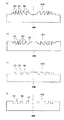
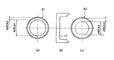
収差補正素子L1の半導体レーザ光源側の光学面S1は、図6に示すように、NA2内の領域に対応する光軸を含む第1領域AREA1と、NA2からNA1までの領域に対応する第2領域AREA2とに分割されており、第1領域AREA1には、図3(a)、(b)に示したような、その内部に階段構造が形成された複数の輪帯が光軸を中心として配列された構造である回折構造(以下、この回折構造を「回折構造HOE」という。)である回折構造HOE1が形成されている。 As shown in FIG. 6, the optical surface S1 of the aberration correction element L1 on the semiconductor laser light source side includes a first area AREA1 including an optical axis corresponding to the area in NA2, and a second area corresponding to the area from NA2 to NA1. The first area AREA1 is divided into a plurality of zones with a staircase structure formed therein as shown in FIGS. 3 (a) and 3 (b). A diffractive structure HOE1 that is a diffractive structure that is an arrayed structure (hereinafter, this diffractive structure is referred to as “diffractive structure HOE”) is formed.
第1領域AREA1に形成された回折構造HOE1において、各輪帯内に形成された階段構造の深さDは、
D・(N1−1)/λ1=2・q (4)
で算出される値に設定され、各輪帯内の分割数Pは5に設定されている。但し、λ1は第1の発光部EP1から射出されるレーザ光束の波長をミクロン単位で表したものであり(ここでは、λ1=0.408μm)、N1は波長λ1に対する収差補正素子L1の媒質屈折率、qは自然数である。
In the diffraction structure HOE1 formed in the first area AREA1, the depth D of the staircase structure formed in each annular zone is
D · (N1-1) / λ1 = 2 · q (4)
The number of divisions P in each annular zone is set to 5. Here, λ1 represents the wavelength of the laser beam emitted from the first light emitting unit EP1 in units of micron (here, λ1 = 0.408 μm), and N1 represents the medium refraction of the aberration correction element L1 with respect to the wavelength λ1. The rate q is a natural number.
光軸方向の深さDがこのように設定された階段構造に対して、第1波長λ1の第1光束が入射した場合、隣接する階段構造間では2×λ1(μm)の光路差が発生し、第1光束は実質的に位相差が与えられないので回折されずにそのまま透過する(本明細書においては「0次回折光」という。)。 When the first light flux having the first wavelength λ1 is incident on the step structure in which the depth D in the optical axis direction is set in this way, an optical path difference of 2 × λ1 (μm) is generated between the adjacent step structures. The first light beam is transmitted without being diffracted because no substantial phase difference is given (referred to as “0th-order diffracted light” in this specification).
また、この階段構造に対して、第3波長λ3(ここでは、λ3=0.785μm)の第3光束が入射した場合、隣接する階段構造間では(2×λ1/(N1−1)・(N3−1)/λ3)×λ3(μm)の光路差が発生する。但し、N3は波長λ3に対する収差補正素子L1の媒質屈折率である。第3波長λ3は(N3−1)/λ3が(N1−1)/λ1の略2倍であるので、隣接する階段構造間では略1×λ3(μm)の光路差が発生し、第3光束も第1光束と同様に、実質的に位相差が与えられないので回折されずに0次回折光として透過する。 In addition, when a third light flux having a third wavelength λ3 (here, λ3 = 0.785 μm) is incident on the staircase structure, (2 × λ1 / (N1-1) · ( An optical path difference of (N3-1) / λ3) × λ3 (μm) occurs. N3 is a medium refractive index of the aberration correction element L1 with respect to the wavelength λ3. Since (N3-1) / λ3 is approximately twice (N1-1) / λ1 in the third wavelength λ3, an optical path difference of approximately 1 × λ3 (μm) occurs between adjacent staircase structures. Similarly to the first light beam, the light beam is not diffracted and is transmitted as zero-order diffracted light because no phase difference is substantially given.
一方、この階段構造に対して、第2波長λ2(ここでは、λ2=0.658μm)の第2光束が入射した場合、隣接する階段構造間では{2×λ1/(N1−1)×(N2−1)/λ2}×λ2={2×0.408/(1.5242−1)×(1.5064−1)/0.658}×λ2=1.199・λ2(μm)の光路差が発生する。各輪帯内の分割数Pは5に設定されているため、隣接する輪帯同士で第2波長λ2の1波長分の光路差が生じることになり((1.199−1)×5≒1)、第2光束は+1次の方向に回折する(+1次回折光)。このときの第2光束の+1次回折光の回折効率は、87.5%となるが、DVDに対する情報の記録/再生には十分な光量である。 On the other hand, when a second light flux having a second wavelength λ2 (here, λ2 = 0.658 μm) is incident on the staircase structure, {2 × λ1 / (N1-1) × ( N2-1) / λ2} × λ2 = {2 × 0.408 / (1.52422-1) × (1.5064-1) /0.658} × λ2 = 1.199 · λ2 (μm) A difference occurs. Since the number of divisions P in each annular zone is set to 5, an optical path difference corresponding to one wavelength of the second wavelength λ2 occurs between adjacent annular zones ((1.199-1) × 5≈ 1) The second light beam is diffracted in the + 1st order direction (+ 1st order diffracted light). At this time, the diffraction efficiency of the + 1st order diffracted light of the second light flux is 87.5%, but the amount of light is sufficient for recording / reproducing information with respect to the DVD.
収差補正素子L1の光ディスク側の光学面S2は、図6に示すように、NA3内の領域に対応する光軸を含む第3領域AREA3と、NA3からNA1までの領域に対応する第4領域AREA4とに分割されており、第3領域AREA3には、図3(c)、(d)に示したような、その内部に階段構造が形成された複数の輪帯が光軸を中心として配列された構造である回折構造HOE2が形成されている。 As shown in FIG. 6, the optical surface S2 on the optical disc side of the aberration correction element L1 includes a third area AREA3 including the optical axis corresponding to the area in NA3, and a fourth area AREA4 corresponding to the area from NA3 to NA1. In the third area AREA3, as shown in FIGS. 3C and 3D, a plurality of annular zones having a staircase structure formed therein are arranged around the optical axis. A diffractive structure HOE2 is formed.
第3領域AREA3に形成された回折構造HOE2において、各輪帯内に形成された階段構造の深さDは、
D・(N1−1)/λ1=5・q (5)
で算出される値に設定され、各輪帯内の分割数Pは2に設定されている。但し、λ1は第3の発光部EP1から射出されるレーザ光束の波長をミクロン単位で表したものであり(ここでは、λ1=0.408μm)、N1は波長λ1に対する収差補正素子L1の媒質屈折率、qは自然数である。
In the diffraction structure HOE2 formed in the third region AREA3, the depth D of the staircase structure formed in each annular zone is
D · (N1-1) / λ1 = 5 · q (5)
The number of divisions P in each annular zone is set to 2. Here, λ1 represents the wavelength of the laser beam emitted from the third light emitting unit EP1 in units of micron (here, λ1 = 0.408 μm), and N1 represents the medium refraction of the aberration correction element L1 with respect to the wavelength λ1. The rate q is a natural number.
光軸方向の深さDがこのように設定された階段構造に対して、第1波長λ1の第1光束が入射した場合、隣接する階段構造間では5×λ1(μm)の光路差が発生し、第1光束は実質的に位相差が与えられないので回折されずに0次回折光として透過する。 When the first light flux having the first wavelength λ1 is incident on the staircase structure in which the depth D in the optical axis direction is set in this way, an optical path difference of 5 × λ1 (μm) is generated between the adjacent staircase structures. However, since the first light beam is not substantially given a phase difference, the first light beam is transmitted without being diffracted as zero-order diffracted light.
また、この階段構造に対して、第2波長λ2(ここでは、λ2=0.658μm)の第2光束が入射した場合、隣接する階段構造間では(5×λ1/(N1−1)・(N2−1)/λ2)×λ2(μm)の光路差が発生する。但し、N2は波長λ2に対する収差補正素子L1の媒質屈折率である。第2波長λ2はλ2/(N2−1)とλ1/(N1−1)の比が略5:3の関係であるので、隣接する階段構造間では略3×λ2(μm)の光路差が発生し、第2光束も第1光束と同様に、実質的に位相差が与えられないので回折されずに0次回折光として透過する。 In addition, when a second light beam having the second wavelength λ2 (here, λ2 = 0.658 μm) is incident on the staircase structure, (5 × λ1 / (N1-1) · ( An optical path difference of (N2-1) / λ2) × λ2 (μm) occurs. N2 is the medium refractive index of the aberration correction element L1 with respect to the wavelength λ2. Since the ratio of λ2 / (N2-1) and λ1 / (N1-1) is approximately 5: 3 for the second wavelength λ2, there is an optical path difference of approximately 3 × λ2 (μm) between adjacent staircase structures. Similarly to the first light beam, the second light beam is transmitted without being diffracted and transmitted as the 0th-order diffracted light similarly to the first light beam.
一方、この階段構造に対して、第3波長λ3(ここでは、λ3=0.785μm)の第3光束が入射した場合、隣接する階段構造間では{5×λ1/(N1−1)×(N3−1)/λ3}×λ3={5×0.408/(1.5242−1)×(1.5050−1)/0.785}×λ3=2.5・λ3(μm)の光路差が発生する。各輪帯内の分割数Pは2に設定されているため、第3光束は±1次の方向にほぼ同じ回折効率で回折する(+1次回折光と−1次回折光)。本実施例では+1次回折光を用いてCDに対する情報の記録/再生を行っており、このときの第2光束の+1次回折光の回折効率は、40%強となる。また−1次回折光は、フレア光となる。 On the other hand, when a third light beam having a third wavelength λ3 (here, λ3 = 0.785 μm) is incident on the staircase structure, {5 × λ1 / (N1-1) × ( N3-1) / λ3} × λ3 = {5 × 0.408 / (1.52422-1) × (1.5050-1) /0.785} × λ3 = 2.5 · λ3 (μm) A difference occurs. Since the number P of divisions in each annular zone is set to 2, the third light beam is diffracted in the ± 1st order direction with substantially the same diffraction efficiency (+ 1st order diffracted light and −1st order diffracted light). In this embodiment, information is recorded / reproduced with respect to the CD using the + 1st order diffracted light, and the diffraction efficiency of the + 1st order diffracted light of the second light flux at this time is slightly over 40%. Further, the −1st order diffracted light becomes flare light.
ここで、+1次回折光の回折効率を高くするために、例えば階段形状の光軸と平行な面と光軸と平行でない方の面の傾きを最適化したり、例えば前記光軸と平行でない面の形状を波面収差的に望ましいとされる形状から少し変えたりすることが、よって改善することが出来る。また、L1を構成する材料の媒質分散を変えて、なおかつ階段形状の分割数Pを変えることで効率を高くすることも可能である。 Here, in order to increase the diffraction efficiency of the + 1st order diffracted light, for example, the inclination of the surface parallel to the staircase-shaped optical axis and the surface not parallel to the optical axis is optimized, or the surface of the surface not parallel to the optical axis is It can be improved by slightly changing the shape from that which is desirable in terms of wavefront aberration. It is also possible to increase the efficiency by changing the medium dispersion of the material constituting L1 and changing the number of divisions P of the staircase shape.
集光素子L2は、第1波長λ1と倍率M1=0と第1保護層PL1との組合せに対して球面収差が最小となるように設計されている。そのため、本実施の形態のように、第1光束に対する第1倍率M1と、第2光束に対する第2倍率M2と、第3光束に対する第2倍率M3とを同じ0とする場合、第1保護層PL1と、第2保護層PL2、第3保護層PL3の厚さの違いにより、集光素子L2と第2保護層PL2とを透過した第2光束の球面収差、及び集光素子L2と第3保護層PL3とを透過した第3光束の球面収差、は補正過剰方向となってしまう。 The condensing element L2 is designed so that the spherical aberration is minimized with respect to the combination of the first wavelength λ1, the magnification M1 = 0, and the first protective layer PL1. Therefore, when the first magnification M1 for the first light flux, the second magnification M2 for the second light flux, and the second magnification M3 for the third light flux are set to the same 0 as in the present embodiment, the first protective layer Due to the difference in the thickness of PL1, the second protective layer PL2, and the third protective layer PL3, the spherical aberration of the second light flux that has passed through the condensing element L2 and the second protective layer PL2, and the condensing elements L2 and the third The spherical aberration of the third light beam transmitted through the protective layer PL3 is in the overcorrected direction.
収差補正素子L1の半導体レーザ光源側の光学面S1設けられた回折構造HOE1と、収差補正素子L1の光ディスク側の光学面S2に設けられた回折構造HOE2、の各輪帯の幅は、それぞれ第2光束、第3光束が入射した場合に、回折作用により+1次回折光に対して補正不足方向の球面収差が付加されるように設定されている。回折構造HOE1、回折構造HOE2による球面収差の付加量と、第1保護層PL1と第2保護層PL2、第3保護層PL3、の厚みの差により発生する補正過剰方向の球面収差とが互いに相殺することで、回折構造HOE1と第2保護層PL2とを透過した第2光束はDVDの情報記録面RL2上で良好なスポットを形成し、回折構造HOE2と第3保護層PL3とを透過した第3光束はCDの情報記録面RL3上で良好なスポットを形成する。 The width of each annular zone of the diffraction structure HOE1 provided on the optical surface S1 on the semiconductor laser light source side of the aberration correction element L1 and the diffraction structure HOE2 provided on the optical surface S2 on the optical disk side of the aberration correction element L1 is respectively It is set so that spherical aberration in the direction of insufficient correction is added to the + 1st order diffracted light by the diffractive action when two light beams and a third light beam are incident. The added amount of spherical aberration due to the diffractive structures HOE1 and HOE2 and the overcorrected spherical aberration caused by the difference in thickness between the first protective layer PL1, the second protective layer PL2, and the third protective layer PL3 cancel each other. As a result, the second light flux transmitted through the diffractive structure HOE1 and the second protective layer PL2 forms a good spot on the information recording surface RL2 of the DVD, and passes through the diffractive structure HOE2 and the third protective layer PL3. The three light beams form a good spot on the information recording surface RL3 of the CD.
このように回折構造HOEを2面に設けることで、3種類の光ディスクに1つの対物光学系で対応しながらそれぞれの光束の倍率M1、M2、M3を全て0にすることが可能となる。全ての結像倍率を0とすることで、第1光ディスクから第3光ディスクまで、全ての光ディスクに対して情報の記録/再生を行う際のトラッキングによるレンズシフトで発生するコマ収差の問題が解決されるので非常に好ましい構成である。 By providing the diffractive structure HOE on two surfaces in this way, it is possible to set all the magnifications M1, M2, and M3 of the respective light beams to 0 while corresponding to three types of optical disks with one objective optical system. By setting all the imaging magnifications to 0, the problem of coma aberration caused by lens shift due to tracking when recording / reproducing information on all optical discs from the first optical disc to the third optical disc is solved. Therefore, this is a very preferable configuration.
また本実施の形態では、収差補正素子L1の両面を回折構造HOEとしたが、少なくとも1つの回折構造HOEを集光素子L2に設けてもよく、回折構造HOEを2面用いれば、上記両面回折構造HOEと同じ効果を得ることが出来る。 In this embodiment, both surfaces of the aberration correction element L1 are diffractive structures HOE. However, at least one diffractive structure HOE may be provided in the light condensing element L2. The same effect as the structure HOE can be obtained.
更に、収差補正素子L1の半導体レーザ光源側光学面S1の第2領域AREA2、又は、光ディスク側光学面S2の第4領域AREA4には、光軸を含む断面形状が鋸歯形状の複数の輪帯から構成された回折構造(以下、この回折構造を「回折構造DOE」という。)である回折構造DOE1、回折構造DOE2、が形成されていても良い。 Further, the second area AREA2 of the optical surface S1 on the semiconductor laser light source side of the aberration correction element L1 or the fourth area AREA4 of the optical surface S2 on the optical disk side includes a plurality of annular zones having a sawtooth cross section including the optical axis. A diffractive structure DOE1 and a diffractive structure DOE2 that are configured diffractive structures (hereinafter, this diffractive structure is referred to as “diffractive structure DOE”) may be formed.
回折構造DOE1は、集光素子L2をプラスチックレンズで構成した場合に特に問題となる、青紫色領域における対物光学系OBJの色収差と、温度変化に伴う球面収差変化、を抑制するための、回折構造DOE2は、集光素子L2をプラスチックレンズで構成した場合に特に問題となる、青紫色と赤色、両領域における対物光学系OBJの色収差と、温度変化に伴う球面収差変化を抑制するための構造である。
The diffractive structure DOE1 is a diffractive structure for suppressing the chromatic aberration of the objective optical system OBJ in the blue-violet region and the change of spherical aberration due to the temperature change, which are particularly problematic when the condensing element L2 is formed of a plastic lens. The
回折構造DOE1において、光軸に最も近い段差の高さd1は、波長390nm〜420nmに対して所望次数の回折光の回折効率が100%となるように設計されている。このように段差の深さが設定された回折構造DOE1に対して、第1光束が入射すると、回折光が95%以上の回折効率で発生し、十分な回折効率が得られるとともに、青紫色領域で色収差補正も可能となる。 In the diffractive structure DOE1, the height d1 of the step closest to the optical axis is designed such that the diffraction efficiency of the desired order diffracted light is 100% with respect to the wavelength of 390 nm to 420 nm. When the first light beam enters the diffractive structure DOE1 in which the depth of the step is set in this way, diffracted light is generated with a diffraction efficiency of 95% or more, and sufficient diffraction efficiency is obtained. Thus, chromatic aberration can be corrected.
回折構造DOE2において、光軸に最も近い段差の高さd1は、例えば波長390nm(収差補正素子L1の、波長390nmに対する屈折率は1.5273である)に対して所望次数の回折光の回折効率が100%となるように設計されている。このように段差の深さが設定された回折構造DOE1に対して、第1光束が入射すると、+2次回折光が96.8%の回折効率で発生し、第2光束が入射すると、+1次回折光が93.9%の回折効率で発生するので、何れの波長領域において十分な回折効率が得られるとともに、青紫色領域で色収差を補正した場合でも、第2光束の波長領域における色収差補正が過剰になりすぎない。ここで、第1光束と第2光束に対して回折効率を振り分けるようにしたが、第1波長λ1に対して最適化することで、第1光束の回折効率を重視した構成としても良い。 In the diffractive structure DOE2, the height d1 of the step closest to the optical axis is, for example, the diffraction efficiency of diffracted light of a desired order with respect to a wavelength of 390 nm (the refractive index of the aberration correction element L1 with respect to the wavelength of 390 nm is 1.5273). Is designed to be 100%. When the first light beam enters the diffractive structure DOE1 in which the step depth is set as described above, + 2nd order diffracted light is generated with a diffraction efficiency of 96.8%, and when the second light beam enters, the + 1st order diffracted light is generated. Occurs at a diffraction efficiency of 93.9%, so that sufficient diffraction efficiency is obtained in any wavelength region, and even when chromatic aberration is corrected in the blue-violet region, chromatic aberration correction in the wavelength region of the second light flux is excessive. Not too much. Here, the diffraction efficiency is distributed to the first light flux and the second light flux. However, by optimizing the first wavelength λ1, the diffraction efficiency of the first light flux may be emphasized.
本実施の形態における対物光学系OBJでは、こういった回折構造DOEを設けていないが、これら回折構造DOEは前述第2領域AREA2、第4領域AREA4以外に集光素子L2の光学面上に設けても良い。その際の回折構造DOEは、集光素子L2で回折構造DOEを設けた光学面全域を1つの領域として1つの回折構造DOEとしても構わないし、前記集光素子L2で回折構造DOEを設けた光学面を、光軸を中心とする同心円状の2又は3つの領域として、それぞれの領域で異なる回折構造DOEを設ける構成としても構わない。これら際のそれぞれの領域における回折効率は、第1光束及至第3光束が共通に透過する領域では第1光束及至第3光束に対して回折効率を振り分けるようにすれば良い(例えば段差の高さを、波長390nm(収差補正素子L1の、波長390nmに対する屈折率は1.5273である)に対して回折効率が100%となるように設計すれば、第1光束が入射すると、+2次回折光が96.8%の回折効率で発生し、第2光束が入射すると、+1次回折光が93.9%の回折効率で発生し、第3光束が入射すると、+1次回折光が99.2%の回折効率で発生する、という回折効率の振り分けが可能である。)し、第1光束と第2光束が共通に透過する領域では第1光束と第2光束に対して回折効率を振り分けるようにすれば良い。また第1波長λ1に対して最適化することで、第1光束の回折効率を重視した構成としても良い。 In the objective optical system OBJ in the present embodiment, such a diffractive structure DOE is not provided, but these diffractive structures DOE are provided on the optical surface of the condensing element L2 in addition to the second area AREA2 and the fourth area AREA4. May be. In this case, the diffractive structure DOE may be a single diffractive structure DOE with the entire optical surface where the diffractive structure DOE is provided by the condensing element L2 as one region. The surface may be configured as two or three concentric regions centered on the optical axis, and different diffractive structures DOE may be provided in each region. The diffraction efficiencies in the respective regions at this time may be set such that the diffraction efficiencies are distributed to the first light flux and the third light flux in the region where the first light flux and the third light flux are transmitted in common (for example, the height of the step). Is designed so that the diffraction efficiency is 100% with respect to the wavelength of 390 nm (the refractive index of the aberration correction element L1 with respect to the wavelength of 390 nm is 1.5273). When the second light beam is incident with a diffraction efficiency of 96.8%, the + 1st order diffracted light is generated with a diffraction efficiency of 93.9%. When the third light beam is incident, the + 1st order diffracted light is 99.2% diffracted. If the diffraction efficiency is distributed between the first light flux and the second light flux in a region where the first light flux and the second light flux are transmitted in common, it is possible to distribute the diffraction efficiency. good. Further, by optimizing with respect to the first wavelength λ1, a configuration in which the diffraction efficiency of the first light flux is emphasized may be adopted.
さらに、回折構造DOE1、DOE2は、青紫色(短波長)領域において、入射光束の波長が長くなった場合に、球面収差が補正不足方向に変化し、入射光束の波長が短くなった場合に、球面収差が補正過剰方向に変化するような球面収差の波長依存性を有する。これにより、環境温度変化に伴い集光素子で発生する球面収差変化を相殺することで、高NAのプラスチックレンズである対物光学系OBJの使用可能な温度範囲を広げている。 Furthermore, the diffractive structures DOE1 and DOE2 have a spherical aberration in the direction of insufficient correction when the wavelength of the incident light beam becomes longer in the blue-violet (short wavelength) region, and the wavelength of the incident light beam becomes shorter. The spherical aberration has a wavelength dependency such that the spherical aberration changes in the overcorrection direction. Accordingly, the usable temperature range of the objective optical system OBJ, which is a high NA plastic lens, is expanded by canceling out the spherical aberration change generated in the light condensing element in accordance with the environmental temperature change.
本実施の形態の収差補正素子L1では、半導体レーザ光源側の光学面S1及びS2に回折構造HOEを形成しているが、光ディスク側の光学面S1及びS2に回折構造DOEを形成してもよいし、光学面S1及びS2の一方に回折構造DOEを形成し、他方に回折構造HOEを形成した構成としてもよい。 In the aberration correction element L1 of the present embodiment, the diffractive structure HOE is formed on the optical surfaces S1 and S2 on the semiconductor laser light source side, but the diffractive structure DOE may be formed on the optical surfaces S1 and S2 on the optical disk side. The diffractive structure DOE may be formed on one of the optical surfaces S1 and S2, and the diffractive structure HOE may be formed on the other.
また、コリメートレンズCOLは、前記第1光束及至第3光束の共通光路内に配置されており、1軸アクチュエータAC2により光軸方向にその位置を調整可能であるように構成されており、上述したように、第1波長λ1と第2波長λ2、第3波長λ3の間の色収差を吸収し、何れの波長の光束も平行光束の状態でコリメートレンズCOLから射出することが出来る。更に、高密度光ディスクHDに対する情報の記録/再生時にコリメートレンズCOLを光軸方向に変移させることで、高密度光ディスクHDの情報記録面RL1上に形成されたスポットの球面収差を補正することが可能となるので、高密度光ディスクHDに対して常に良好な記録/再生特性を維持することができる。 Further, the collimating lens COL is disposed in the common optical path of the first light flux and the third light flux, and is configured so that the position thereof can be adjusted in the optical axis direction by the uniaxial actuator AC2. As described above, the chromatic aberration between the first wavelength λ1, the second wavelength λ2, and the third wavelength λ3 is absorbed, and a light beam of any wavelength can be emitted from the collimator lens COL in the state of a parallel light beam. Furthermore, the spherical aberration of the spot formed on the information recording surface RL1 of the high-density optical disk HD can be corrected by moving the collimating lens COL in the optical axis direction when recording / reproducing information on the high-density optical disk HD. Therefore, it is possible to always maintain good recording / reproducing characteristics for the high-density optical disc HD.
コリメートレンズCOLの位置調整により補正する球面収差の発生原因は、例えば、青紫色半導体レーザLD1の製造誤差による波長ばらつき、温度変化に伴う対物光学系OBJの屈折率変化や屈折率分布、2層ディスク、4層ディスク等の多層ディスクに対する記録/再生時における層間のフォーカスジャンプ、保護層PL1の製造誤差による厚みばらつきや厚み分布、等である。 The cause of the spherical aberration corrected by adjusting the position of the collimating lens COL is, for example, wavelength variation due to manufacturing error of the blue-violet semiconductor laser LD1, refractive index change or refractive index distribution of the objective optical system OBJ due to temperature change, two-layer disk These include focus jumps between layers at the time of recording / reproducing with respect to a multi-layer disc such as a four-layer disc, thickness variation and thickness distribution due to manufacturing errors of the protective layer PL1, and the like.
以上の説明では、高密度光ディスクHDの情報記録面RL1上に形成されたスポットの球面収差を補正する場合について説明したが、DVDの情報記録面RL2上に形成されたスポットの球面収差をコリメートレンズCOLの位置調整により補正するようにしても良い。 In the above description, the case of correcting the spherical aberration of the spot formed on the information recording surface RL1 of the high-density optical disc HD has been described. However, the spherical aberration of the spot formed on the information recording surface RL2 of the DVD is corrected by the collimating lens. You may make it correct | amend by position adjustment of COL.
また、本実施の形態では、NA2又はNA3に対応した開口制限を行うための開口素子として、接合部材Bを介して対物光学系OBJと一体化された開口制限素子APを備えている。そして、2軸アクチュエータAC1により、開口制限素子APと対物光学系OBJとを一体にトラッキング駆動させるようになっている。 In the present embodiment, the aperture limiting element AP integrated with the objective optical system OBJ via the joining member B is provided as an aperture element for performing aperture limitation corresponding to NA2 or NA3. The aperture limiting element AP and the objective optical system OBJ are integrally driven to track by the biaxial actuator AC1.
開口制限素子APの光学面上には、透過率の波長選択性を有する波長選択フィルタWFが形成されている。この波長選択フィルタWFを、NA2の開口制限に対応させる場合には、NA2内の領域では第1波長λ1乃至第3波長λ3の全ての波長を透過させ、NA2外の領域では第2波長及び第3波長λ3を遮断し、第1波長λ1のみを透過する透過率の波長選択性を持たせることができる。一方、波長選択フィルタWFを、NA3の開口制限に対応させる場合には、NA3内の領域では第1波長λ1乃至第3波長λ3の全ての波長を透過させ、NA3外の領域では第3波長λ3のみを遮断し、第1波長λ1及び第2波長λ2を透過する透過率の波長選択性を持たせることができる On the optical surface of the aperture limiting element AP, a wavelength selection filter WF having wavelength selectivity of transmittance is formed. When this wavelength selection filter WF is adapted to the aperture restriction of NA2, all the wavelengths from the first wavelength λ1 to the third wavelength λ3 are transmitted in the region inside NA2, and the second wavelength and the second wavelength are transmitted in the region outside NA2. It is possible to block the three wavelengths λ3 and to have wavelength selectivity of transmittance that transmits only the first wavelength λ1. On the other hand, when the wavelength selection filter WF is adapted to the aperture restriction of NA3, all the wavelengths from the first wavelength λ1 to the third wavelength λ3 are transmitted in the region inside NA3, and the third wavelength λ3 is transmitted in the region outside NA3. The wavelength selectivity of the transmittance that transmits the first wavelength λ1 and the second wavelength λ2 can be provided.
なお、収差補正素子L1の光学機能面上に波長選択フィルタWFを形成してもよく、あるいは、集光素子L2の光学機能面上に形成してもよい。また、回折構造HOEはNA2内に対応する第1領域AREA1内に形成されているので、第2領域AREA2を通過する第2光束はDVDの情報記録面上RL2上へのスポット形成に寄与しないフレア成分となる。これは、対物光学系OBJがNA2に対する開口制限機能を有しているのと透過であり、この機能によりNA2に対応した開口制限が行われる。 The wavelength selection filter WF may be formed on the optical function surface of the aberration correction element L1, or may be formed on the optical function surface of the light condensing element L2. Further, since the diffractive structure HOE is formed in the first area AREA1 corresponding to NA2, the second light flux that passes through the second area AREA2 is a flare that does not contribute to spot formation on the information recording surface RL2 of the DVD. Become an ingredient. This means that the objective optical system OBJ has an aperture limiting function for NA2, and transmission is performed, and aperture limiting corresponding to NA2 is performed by this function.
また、開口の制限方法としては、波長選択フィルタWFを利用する方法だけでなく、機械的に絞りを切り替える方式や後述する液晶位相制御素子LCDを利用する方式でも良い。 Further, as a method of limiting the aperture, not only a method using the wavelength selection filter WF, but also a method of mechanically switching the diaphragm or a method using a liquid crystal phase control element LCD described later.
ビーム整形素子SHは、半導体レーザからの楕円光束を円形、又は略円形形状の光束に変換するための素子であり、ビーム整形素子SHを用いることで、半導体レーザからの光の光利用効率を向上させることが出来、ピックアップの高性能化が達成される。 The beam shaping element SH is an element for converting the elliptical light beam from the semiconductor laser into a circular or substantially circular light beam. By using the beam shaping element SH, the light utilization efficiency of the light from the semiconductor laser is improved. It is possible to improve the pickup performance.
このようなビーム整形素子SHは、例えば1方向のみに曲率を持つシリンドリカル面形状の単玉レンズで構成されたり、2つの直交する方向について曲率半径の異なるアナモフィック面で構成したものであったりする。 Such a beam shaping element SH is composed of, for example, a cylindrical single lens having a curvature only in one direction, or an anamorphic surface having different curvature radii in two orthogonal directions.
本実施例において用いている構成のように、2波長一体化レーザの光路中にビーム整形素子SHを配置した場合には、2つのレーザ発光部とビーム整形素子SHの位置関係が、例えばシリンドリカル面で構成されるビーム整形素子については、ビーム整形素子の面が曲率を持たない方向と、前記2つのレーザ発光部の並び方向を一致さることが望ましく、例えばアナモフィック面で構成させるビーム整形素子については、ビーム整形素子の面が曲率の大きくなる方向と、前記2つのレーザ発光部の並び方向を一致させることが望ましい。ビーム整形素子SHと2つのレーザ発光部の位置関係を上述のようにすることで、ビーム整形素子による収差の影響をなくす、又は低減することが可能となる。 When the beam shaping element SH is disposed in the optical path of the two-wavelength integrated laser as in the configuration used in the present embodiment, the positional relationship between the two laser emission units and the beam shaping element SH is, for example, a cylindrical surface. It is desirable that the direction of the surface of the beam shaping element having no curvature coincides with the direction in which the two laser light emitting units are aligned. For example, for a beam shaping element configured with an anamorphic surface, It is desirable that the direction in which the surface of the beam shaping element has a large curvature coincides with the direction in which the two laser light emitting units are arranged. By making the positional relationship between the beam shaping element SH and the two laser light emitting portions as described above, it becomes possible to eliminate or reduce the influence of aberration caused by the beam shaping element.
しかし、レーザ発光部の並びと、半導体レーザの楕円光束長軸方向の向きの関係によっては上記の限りではなく、ビーム整形素子SHでビーム整形する方向と半導体レーザ楕円光束の向きを所望のものとして複数光源に対応なければならない。 However, depending on the relationship between the arrangement of the laser light emitting units and the direction of the major axis direction of the elliptical light beam of the semiconductor laser, this is not limited to the above. Must support multiple light sources.
[第2の実施の形態]
図7は、高密度光ディスクHD(第1光ディスク)とDVD(第2光ディスク)とCD(第3光ディスク)との何れに対しても、簡略な構成で適切に情報の記録/再生を行える第2の光ピックアップ装置PU2の構成を概略的に示す図である。高密度光ディスクHDの光学的仕様は、第1波長λ1=408nm、第1保護層PL1の厚さt1=0.1mm、開口数NA1=0.85であり、DVDの光学的仕様は、第2波長λ2=658nm、第2保護層PL2の厚さt2=0.6mm、開口数NA2=0.60であり、CDの光学的仕様は、第3波長λ3=785nm、第3保護層PL3の厚さt3=1.2mm、開口数NA3=0.45である。
[Second Embodiment]
FIG. 7 shows a second example in which information can be appropriately recorded / reproduced with a simple configuration for any of the high-density optical disc HD (first optical disc), DVD (second optical disc), and CD (third optical disc). It is a figure which shows schematically the structure of this optical pick-up apparatus PU2. The optical specifications of the high-density optical disc HD are the first wavelength λ1 = 408 nm, the thickness t1 of the first protective layer PL1 is 0.1 mm, and the numerical aperture NA1 = 0.85. The optical specification of the DVD is the second The wavelength λ2 = 658 nm, the thickness t2 of the second protective layer PL2 = 0.6 mm, the numerical aperture NA2 = 0.60, and the optical specifications of the CD are the third wavelength λ3 = 785 nm and the thickness of the third protective layer PL3. The length t3 = 1.2 mm and the numerical aperture NA3 = 0.45.
第1光ディスク〜第3光ディスクの記録密度(ρ1〜ρ3)は、ρ3<ρ2<ρ1となっており、第1光ディスク〜第3光ディスクに対して情報の記録及び/又は再生を行う際の、対物光学系OBJの倍率(第1倍率M1〜第3倍率M3)は、M1=M2=M3=0となっている。但し、波長、保護層の厚さ、開口数、記録密度及び倍率の組合せはこれに限られない。 The recording densities (ρ1 to ρ3) of the first optical disc to the third optical disc are ρ3 <ρ2 <ρ1, and the objective when recording and / or reproducing information on the first optical disc to the third optical disc is set. The magnification (first magnification M1 to third magnification M3) of the optical system OBJ is M1 = M2 = M3 = 0. However, the combination of wavelength, protective layer thickness, numerical aperture, recording density, and magnification is not limited to this.
光ピックアップ装置PU2は、高密度光ディスクHDに対して情報の記録/再生を行う場合に発光され408nmのレーザ光束(第1光束)を射出する第1の発光部EP1(第1光源)と、DVDに対して情報の記録/再生を行う場合に発光され658nmのレーザ光束(第2光束)を射出する第2の発光部EP2(第2光源)とを同一パッケージ内に収容した(一体化された)2レーザ1パッケージ2L1Pと、CDに対して情報の記録/再生を行う場合に発光され785nmのレーザ光束(第3光束)を射出する赤外半導体レーザLD3(第3光源)と光検出器PD3とが一体化されたホログラムレーザHLと、その光学面上に位相構造としての回折構造が形成された収差補正素子L1とこの収差補正素子L1を透過したレーザ光束を情報記録面RL1、RL2,RL3上に集光させる機能を有する両面が非球面とされた集光素子L2とから構成された対物光学系OBJ、開口制限素子AP、2軸アクチュエータAC1、1軸アクチュエータAC2、高密度光ディスクHDの開口数NA1に対応した絞りSTO、ダイクロイックプリズムDPS、コリメートレンズCOL(可動素子)、カップリングレンズCUL、ビーム整形素子SHと、ビームエキスパンダEXPとから構成されている。尚、対物光学系OBJについては、第1の光ピックアップ装置PU1に搭載したものと同様なものを用いることができるので、その説明は省略する。 The optical pickup device PU2 includes a first light emitting unit EP1 (first light source) that emits a laser beam (first beam) of 408 nm that is emitted when information is recorded / reproduced with respect to the high-density optical disc HD, and a DVD. And a second light emitting unit EP2 (second light source) that emits a laser beam (second beam) of 658 nm emitted when recording / reproducing information is accommodated in the same package (integrated) 2 Laser 1 package 2L1P, an infrared semiconductor laser LD3 (third light source) emitting a 785 nm laser beam (third beam) when recording / reproducing information on a CD, and a photodetector PD3 Are integrated into a hologram laser HL, an aberration correction element L1 having a diffraction structure as a phase structure on its optical surface, and a laser beam transmitted through the aberration correction element L1. Objective optical system OBJ, aperture limiting element AP, biaxial actuator AC1, monoaxial actuator AC2 including condensing element L2 having both surfaces aspherical and having a function of condensing on recording surfaces RL1, RL2, and RL3 The aperture STO, the dichroic prism DPS, the collimating lens COL (movable element), the coupling lens CUL, the beam shaping element SH, and the beam expander EXP corresponding to the numerical aperture NA1 of the high-density optical disk HD. Since the objective optical system OBJ can be the same as that mounted on the first optical pickup device PU1, description thereof is omitted.
光ピックアップ装置PU2において、高密度光ディスクHDに対して情報の記録/再生を行う場合には、2レーザ1パッケージ2L1Pを作動させて第1の発光部EP1を発光させる。第1の発光部EP1から射出された発散光束は、図7において実線でその光線経路を描いたように、ビーム整形素子SHを透過することにより、その断面形状が楕円形から円形に整形され、ダイクロイックプリズムDPSを透過し、コリメートレンズCOLを経て平行光束とされた後、ビームエキスパンダEXPを透過し、絞りSTOにより光束径が規制され、開口制限素子APを透過し、対物光学系OBJによって第1保護層PL1を介して情報記録面RL1上に形成されるスポットとなる。対物光学系OBJは、その周辺に配置された2軸アクチュエータAC1によってフォーカシングやトラッキングを行う。情報記録面RL1で情報ピットにより変調された反射光束は、再び対物光学系OBJ、開口制限素子AP、ビームエキスパンダEXPを透過し、コリメートレンズCOLによって収斂光束とされ、ダイクロイックプリズムDPS、ビーム整形素子BSを透過した後、2レーザ1パッケージ内又はその近傍に配置された光検出器(不図示)で受光される。かかる光検出器の出力信号を用いて、高密度光ディスクHDに記録された情報を読み取ることができる。 When recording / reproducing information with respect to the high-density optical disc HD in the optical pickup device PU2, the two-laser one package 2L1P is operated to cause the first light emitting unit EP1 to emit light. The divergent light beam emitted from the first light emitting unit EP1 passes through the beam shaping element SH as depicted by the solid line in FIG. 7, so that its cross-sectional shape is shaped from an ellipse to a circle, The light beam passes through the dichroic prism DPS and is converted into a parallel light beam through the collimator lens COL, then passes through the beam expander EXP, the light beam diameter is restricted by the stop STO, and the light passes through the aperture limiting element AP, and is reflected by the objective optical system OBJ. 1 It becomes a spot formed on the information recording surface RL1 through the protective layer PL1. The objective optical system OBJ performs focusing and tracking by a biaxial actuator AC1 disposed around the objective optical system OBJ. The reflected light beam modulated by the information pits on the information recording surface RL1 is transmitted again through the objective optical system OBJ, the aperture limiting element AP, and the beam expander EXP, and is converged by the collimator lens COL, and is reflected by the dichroic prism DPS, the beam shaping element. After passing through the BS, it is received by a photodetector (not shown) arranged in or near the two lasers 1 package. Information recorded on the high-density optical disk HD can be read using the output signal of the photodetector.
また、光ピックアップ装置PU2においてDVDに対して情報の記録/再生を行う場合には、第2光束が平行光束の状態でコリメートレンズCOLから射出されるようになっており、又1軸アクチュエータAC2によりビームエキスパンダEXPのレンズL1を移動させる。その後、2レーザ1パッケージ2L1Pを作動させて第2の発光部EP2を発光させる。但し、前記第2の発光部EP2を発光させた後、最適位置を探索しながらビームエキスパンダEXPのレンズL1を移動させても良い。 Further, when information is recorded / reproduced with respect to the DVD in the optical pickup device PU2, the second light beam is emitted from the collimator lens COL in the state of a parallel light beam, and also by the uniaxial actuator AC2. The lens L1 of the beam expander EXP is moved. Thereafter, the 2 laser 1 package 2L1P is operated to cause the second light emitting unit EP2 to emit light. However, the lens L1 of the beam expander EXP may be moved while searching for the optimal position after the second light emitting unit EP2 emits light.
第2の発光部EP2から射出された発散光束は、図7において点線でその光線経路を描いたように、ビーム整形素子SHを透過することにより、その断面形状が楕円形から円形に整形され、ダイクロイックプリズムDPSを透過し、コリメートレンズCOLを経て平行光束とされた後、ビームエキスパンダEXPを透過し、絞りSTOにより光束径が規制され、開口制限素子APを透過し、対物光学系OBJによって第2保護層PL2を介して情報記録面RL2上に形成されるスポットとなる。対物光学系OBJは、その周辺に配置された2軸アクチュエータAC1によってフォーカシングやトラッキングを行う。情報記録面RL2で情報ピットにより変調された反射光束は、再び対物光学系OBJ、開口制限素子AP、ビームエキスパンダEXPを透過し、コリメートレンズCOLによって収斂光束とされ、ダイクロイックプリズムDPS、ビーム整形素子BSを透過した後、2レーザ1パッケージ内又はその近傍に配置された光検出器(不図示)で受光される。かかる光検出器の出力信号を用いて、DVDに記録された情報を読み取ることができる。 The divergent light beam emitted from the second light emitting unit EP2 passes through the beam shaping element SH, as shown by the dotted line in FIG. 7, so that its cross-sectional shape is shaped from an ellipse to a circle, The light beam passes through the dichroic prism DPS and is converted into a parallel light beam through the collimator lens COL, then passes through the beam expander EXP, the light beam diameter is restricted by the stop STO, and the light passes through the aperture limiting element AP, and is reflected by the objective optical system OBJ. 2 Spots formed on the information recording surface RL2 via the protective layer PL2. The objective optical system OBJ performs focusing and tracking by a biaxial actuator AC1 disposed around the objective optical system OBJ. The reflected light beam modulated by the information pits on the information recording surface RL2 is transmitted again through the objective optical system OBJ, the aperture limiting element AP, and the beam expander EXP, and is converged by the collimating lens COL, and is reflected by the dichroic prism DPS, the beam shaping element. After passing through the BS, it is received by a photodetector (not shown) arranged in or near the two lasers 1 package. Information recorded on the DVD can be read using the output signal of the photodetector.
また、光ピックアップ装置PU2においてCDに対して情報の記録/再生を行う場合には、第3光束が平行光束の状態でコリメートレンズCOLから射出されるようになっており、又1軸アクチュエータAC2によりビームエキスパンダEXPのレンズL1を移動させる。その後、ホログラムレーザHLの半導体レーザLD3を発光させる。但し、前記半導体レーザLD3を発光させた後、最適位置を探索しながらコリメートレンズCOLを移動させても良い。 Further, when information is recorded / reproduced with respect to the CD in the optical pickup device PU2, the third light beam is emitted from the collimator lens COL in the state of a parallel light beam, and is also controlled by the uniaxial actuator AC2. The lens L1 of the beam expander EXP is moved. Thereafter, the semiconductor laser LD3 of the hologram laser HL is caused to emit light. However, after emitting the semiconductor laser LD3, the collimating lens COL may be moved while searching for the optimum position.
半導体レーザLD3から射出された発散光束は、図7において一点鎖線でその光線経路を描いたように、カップリングレンズCULを通過し、ダイクロイックプリズムDPSで反射され、コリメートレンズCOLを経て平行光束とされた後、ビームエキスパンダEXPを透過し、絞りSTOにより光束径が規制され、開口制限素子APを透過し、対物光学系OBJによって第3保護層PL3を介して情報記録面RL3上に形成されるスポットとなる。対物光学系OBJは、その周辺に配置された2軸アクチュエータAC1によってフォーカシングやトラッキングを行う。情報記録面RL3で情報ピットにより変調された反射光束は、再び対物光学系OBJ、開口制限素子AP、ビームエキスパンダEXPを透過し、コリメートレンズCOLによって収斂光束とされ、ダイクロイックプリズムDPSで反射されて、カップリングレンズCULを透過した後、ホログラムレーザHLの光検出器PD3で受光される。光検出器PD3の出力信号を用いて、CDに記録された情報を読み取ることができる。 The divergent light beam emitted from the semiconductor laser LD3 passes through the coupling lens CUL, is reflected by the dichroic prism DPS, and is converted into a parallel light beam through the collimator lens COL, as depicted in the dashed line in FIG. After that, the beam expander EXP is transmitted, the beam diameter is regulated by the stop STO, the aperture limiting element AP is transmitted, and the objective optical system OBJ is formed on the information recording surface RL3 via the third protective layer PL3. Become a spot. The objective optical system OBJ performs focusing and tracking by a biaxial actuator AC1 disposed around the objective optical system OBJ. The reflected light beam modulated by the information pits on the information recording surface RL3 is transmitted again through the objective optical system OBJ, the aperture limiting element AP, and the beam expander EXP, and is converged by the collimator lens COL and reflected by the dichroic prism DPS. After passing through the coupling lens CUL, the light is received by the photodetector PD3 of the hologram laser HL. Information recorded on the CD can be read using the output signal of the photodetector PD3.
本実施の形態において、凹レンズL1と凸レンズL2とからなる収差補正素子であるビームエキスパンダEXPは、前記第1光束及至第3光束の共通光路内に配置されており、凹レンズL1が1軸アクチュエータAC2により光軸方向にその位置を調整可能であるように構成されており、コリメートレンズCOLから射出された何れの波長の平行光束も、平行光束の状態を維持したまま射出することが出来る。更に、高密度光ディスクHDに対する情報の記録/再生時に凹レンズL1を光軸方向に変移させることで、高密度光ディスクHDの情報記録面RL1上に形成されたスポットの球面収差を補正することが可能となるので、高密度光ディスクHDに対して常に良好な記録/再生特性を維持することができる。 In the present embodiment, a beam expander EXP, which is an aberration correction element composed of a concave lens L1 and a convex lens L2, is disposed in a common optical path of the first and third light beams, and the concave lens L1 is a uniaxial actuator AC2. Thus, the position can be adjusted in the optical axis direction, and a parallel light flux of any wavelength emitted from the collimating lens COL can be emitted while maintaining the state of the parallel light flux. Furthermore, the spherical aberration of the spot formed on the information recording surface RL1 of the high-density optical disk HD can be corrected by moving the concave lens L1 in the optical axis direction when recording / reproducing information on the high-density optical disk HD. Therefore, it is possible to always maintain good recording / reproduction characteristics for the high-density optical disc HD.
凹レンズL1の位置調整により補正する球面収差の発生原因は、例えば、青紫色半導体レーザLD1の製造誤差による波長ばらつき、温度変化に伴う対物光学系OBJの屈折率変化や屈折率分布、2層ディスク、4層ディスク等の多層ディスクに対する記録/再生時における層間のフォーカスジャンプ、保護層PL1の製造誤差による厚みばらつきや厚み分布、等である。 The cause of spherical aberration to be corrected by adjusting the position of the concave lens L1 is, for example, wavelength variation due to manufacturing error of the blue-violet semiconductor laser LD1, refractive index change or refractive index distribution of the objective optical system OBJ due to temperature change, two-layer disk, These include focus jumps between layers at the time of recording / reproduction with respect to a multi-layer disc such as a four-layer disc, and thickness variations and thickness distributions due to manufacturing errors of the protective layer PL1.
以上の説明では、高密度光ディスクHDの情報記録面RL1上に形成されたスポットの球面収差を補正する場合について説明したが、DVDの情報記録面RL2上に形成されたスポットの球面収差を凹レンズL1の位置調整により補正するようにしても良い。 In the above description, the case of correcting the spherical aberration of the spot formed on the information recording surface RL1 of the high-density optical disc HD has been described. However, the spherical aberration of the spot formed on the information recording surface RL2 of the DVD is corrected to the concave lens L1. You may make it correct | amend by position adjustment.
[第3の実施の形態]
図8は、高密度光ディスクHD(第1光ディスク)とDVD(第2光ディスク)とCD(第3光ディスク)との何れに対しても、簡略な構成で適切に情報の記録/再生を行える第3の光ピックアップ装置PU3の構成を概略的に示す図である。高密度光ディスクHDの光学的仕様は、第1波長λ1=408nm、第1保護層PL1の厚さt1=0.1mm、開口数NA1=0.85であり、DVDの光学的仕様は、第2波長λ2=658nm、第2保護層PL2の厚さt2=0.6mm、開口数NA2=0.60であり、CDの光学的仕様は、第3波長λ3=785nm、第3保護層PL3の厚さt3=1.2mm、開口数NA3=0.45である。
[Third Embodiment]
FIG. 8 shows a third example in which information can be appropriately recorded / reproduced with a simple configuration for any of the high-density optical disc HD (first optical disc), DVD (second optical disc), and CD (third optical disc). It is a figure which shows schematically the structure of this optical pick-up apparatus PU3. The optical specifications of the high-density optical disc HD are the first wavelength λ1 = 408 nm, the thickness t1 of the first protective layer PL1 is 0.1 mm, and the numerical aperture NA1 = 0.85. The optical specification of the DVD is the second The wavelength λ2 = 658 nm, the thickness t2 of the second protective layer PL2 = 0.6 mm, the numerical aperture NA2 = 0.60, and the optical specifications of the CD are the third wavelength λ3 = 785 nm and the thickness of the third protective layer PL3. The length t3 = 1.2 mm and the numerical aperture NA3 = 0.45.
第1光ディスク〜第3光ディスクの記録密度(ρ1〜ρ3)は、ρ3<ρ2<ρ1となっており、第1光ディスク〜第3光ディスクに対して情報の記録及び/又は再生を行う際の、対物光学系OBJの倍率(第1倍率M1〜第3倍率M3)は、M1=M2=M3=0となっている。但し、波長、保護層の厚さ、開口数、記録密度及び倍率の組合せはこれに限られない。 The recording densities (ρ1 to ρ3) of the first optical disc to the third optical disc are ρ3 <ρ2 <ρ1, and the objective when recording and / or reproducing information on the first optical disc to the third optical disc is set. The magnification (first magnification M1 to third magnification M3) of the optical system OBJ is M1 = M2 = M3 = 0. However, the combination of wavelength, protective layer thickness, numerical aperture, recording density, and magnification is not limited to this.
光ピックアップ装置PU3は、高密度光ディスクHDに対して情報の記録/再生を行う場合に発光され408nmのレーザ光束(第1光束)を射出する第1の発光部EP1(第1光源)と、DVDに対して情報の記録/再生を行う場合に発光され658nmのレーザ光束(第2光束)を射出する第2の発光部EP2(第2光源)と、CDに対して情報の記録/再生を行う場合に発光され785nmのレーザ光束(第3光束)を射出する発光部EP3とを同一パッケージ内に収容した(一体化された)3レーザ1パッケージ3L1Pと、光検出器PDと、その光学面上に位相構造としての回折構造が形成された収差補正素子L1とこの収差補正素子L1を透過したレーザ光束を情報記録面RL1、RL2,RL3上に集光させる機能を有する両面が非球面とされた集光素子L2とから構成された対物光学系OBJ、開口制限素子AP、2軸アクチュエータAC1、1軸アクチュエータAC2、高密度光ディスクHDの開口数NA1に対応した絞りSTO、偏光ビームスプリッタPBS、コリメートレンズCOL(可動素子)、センサ用レンズSL、ビーム整形素子SH、1/4波長板QWPとから構成されている。尚、対物光学系OBJについては、第1の光ピックアップ装置PU1に搭載したものと同様なものを用いることができるので、その説明は省略する。又、3レーザ1パッケージ3L1Pにおいて、光学系の設計上最も厳しい第1の発光部EP1が、光ピックアップ装置PU3の光軸上に配置されていると好ましいが、第2の発光部EP2又は第3の発光部EP3を光ピックアップ装置PU3の光軸上に配置しても良く、或いは全ての発光部を軸外に配置しても良い。更に、第3の実施の形態(及び後述する第4の実施の形態)では、光検出器を別に設けているが、3レーザ1パッケージ3L1P内部又はその近傍に設けることもでき、それにより偏光ビームスプリッタPBSと光検出器PDとを省略できる。 The optical pickup device PU3 includes a first light emitting unit EP1 (first light source) that emits a laser beam (first beam) of 408 nm that is emitted when information is recorded / reproduced with respect to the high-density optical disk HD, and a DVD. And recording / reproducing information with respect to the CD, and a second light-emitting unit EP2 (second light source) that emits a 658 nm laser beam (second beam) when recording / reproducing information with respect to the CD. 3 laser 1 package 3L1P which accommodates (integrated) light emitting part EP3 which emits light in this case and emits a laser beam of 785 nm (third beam) in the same package, photodetector PD, and its optical surface Both of which have a function of condensing the aberration correction element L1 having a diffraction structure as a phase structure and a laser beam transmitted through the aberration correction element L1 onto the information recording surfaces RL1, RL2 and RL3. An objective optical system OBJ composed of a condensing element L2 having an aspherical surface, an aperture limiting element AP, a biaxial actuator AC1, a monoaxial actuator AC2, a diaphragm STO corresponding to the numerical aperture NA1 of the high density optical disk HD, and polarization It is composed of a beam splitter PBS, a collimating lens COL (movable element), a sensor lens SL, a beam shaping element SH, and a quarter wavelength plate QWP. Since the objective optical system OBJ can be the same as that mounted on the first optical pickup device PU1, description thereof is omitted. In the 3 laser 1 package 3L1P, it is preferable that the first light emitting portion EP1 that is the most severe in terms of optical system design is disposed on the optical axis of the optical pickup device PU3. The light emitting part EP3 may be arranged on the optical axis of the optical pickup device PU3, or all the light emitting parts may be arranged off-axis. Further, in the third embodiment (and the fourth embodiment to be described later), a photodetector is provided separately, but it can also be provided in or near the three lasers 1 package 3L1P, whereby a polarized beam The splitter PBS and the photodetector PD can be omitted.
光ピックアップ装置PU3において、高密度光ディスクHDに対して情報の記録/再生を行う場合には、3レーザ1パッケージ3L1Pを作動させて第1の発光部EP1を発光させる。第1の発光部EP1から射出された発散光束は、図8において実線でその光線経路を描いたように、ビーム整形素子SHを透過することにより、その断面形状が楕円形から円形に整形され、偏光ビームスプリッタPBSを透過し、コリメートレンズCOLを経て平行光束とされた後、1/4波長板QWPを通過し、絞りSTOにより光束径が規制され、開口制限素子APを透過し、対物光学系OBJによって第1保護層PL1を介して情報記録面RL1上に形成されるスポットとなる。対物光学系OBJは、その周辺に配置された2軸アクチュエータAC1によってフォーカシングやトラッキングを行う。情報記録面RL1で情報ピットにより変調された反射光束は、再び対物光学系OBJ、開口制限素子AP、1/4波長板QWPを通過し、コリメートレンズCOLによって収斂光束とされ、偏光ビームスプリッタPBSで反射されて、センサ用レンズSLを透過した後、光検出器PDで受光される。光検出器PDの出力信号を用いて、高密度光ディスクHDに記録された情報を読み取ることができる。 In the optical pickup device PU3, when information is recorded / reproduced with respect to the high-density optical disk HD, the 3 laser 1 package 3L1P is operated to cause the first light emitting unit EP1 to emit light. The divergent light beam emitted from the first light emitting unit EP1 passes through the beam shaping element SH as illustrated by the solid line in FIG. 8, so that its cross-sectional shape is shaped from an ellipse to a circle, After passing through the polarization beam splitter PBS and passing through the collimating lens COL, it is converted into a parallel beam, and then passes through the quarter-wave plate QWP, the beam diameter is regulated by the stop STO, and the aperture limiting element AP is transmitted. It becomes a spot formed on the information recording surface RL1 via the first protective layer PL1 by OBJ. The objective optical system OBJ performs focusing and tracking by a biaxial actuator AC1 disposed around the objective optical system OBJ. The reflected light beam modulated by the information pits on the information recording surface RL1 passes again through the objective optical system OBJ, the aperture limiting element AP, and the quarter wavelength plate QWP, and is converged by the collimator lens COL, and is reflected by the polarization beam splitter PBS. After being reflected and transmitted through the sensor lens SL, the light is received by the photodetector PD. Information recorded on the high-density optical disk HD can be read using the output signal of the photodetector PD.
また、光ピックアップ装置PU3においてDVDに対して情報の記録/再生を行う場合には、第2光束が平行光束の状態でコリメートレンズCOLから射出されるように、1軸アクチュエータAC2によりコリメートレンズCOLを移動させる。その後、3レーザ1パッケージ3L1Pを作動させて第2の発光部EP2を発光させる。但し、前記第2の発光部EP2を発光させた後、最適位置を探索しながらコリメートレンズCOLを移動させても良い。 In addition, when recording / reproducing information with respect to the DVD in the optical pickup device PU3, the collimating lens COL is moved by the uniaxial actuator AC2 so that the second light beam is emitted from the collimating lens COL in the state of a parallel light beam. Move. Thereafter, the 3 laser 1 package 3L1P is operated to cause the second light emitting unit EP2 to emit light. However, the collimating lens COL may be moved while searching for the optimum position after the second light emitting unit EP2 emits light.
第2の発光部EP2から射出された発散光束は、図8において点線でその光線経路を描いたように、ビーム整形素子SHを透過することにより、その断面形状が楕円形から円形に整形され、偏光ビームスプリッタPBSを透過し、コリメートレンズCOLを経て平行光束とされた後、絞りSTOにより光束径が規制され、1/4波長板QWP、開口制限素子APを透過し、対物光学系OBJによって第2保護層PL2を介して情報記録面RL2上に形成されるスポットとなる。対物光学系OBJは、その周辺に配置された2軸アクチュエータAC1によってフォーカシングやトラッキングを行う。情報記録面RL2で情報ピットにより変調された反射光束は、再び対物光学系OBJ、開口制限素子AP、1/4波長板QWPを通過し、コリメートレンズCOLによって収斂光束とされ、偏光ビームスプリッタPBSで反射されて、センサ用レンズSLを透過した後、ホログラムレーザHLの光検出器PD3で受光される。光検出器PD3の出力信号を用いて、DVDに記録された情報を読み取ることができる。 The divergent light beam emitted from the second light emitting unit EP2 passes through the beam shaping element SH as depicted by the dotted line in FIG. 8, so that its cross-sectional shape is shaped from an ellipse to a circle, After passing through the polarizing beam splitter PBS and being converted into a parallel beam through the collimating lens COL, the beam diameter is regulated by the stop STO, the quarter-wave plate QWP, the aperture limiting element AP, and the first optical system OBJ. 2 Spots formed on the information recording surface RL2 via the protective layer PL2. The objective optical system OBJ performs focusing and tracking by a biaxial actuator AC1 disposed around the objective optical system OBJ. The reflected light beam modulated by the information pits on the information recording surface RL2 passes again through the objective optical system OBJ, the aperture limiting element AP, and the quarter wavelength plate QWP, and is converged by the collimator lens COL. After being reflected and transmitted through the sensor lens SL, the light is received by the photodetector PD3 of the hologram laser HL. Information recorded on the DVD can be read using the output signal of the photodetector PD3.
また、光ピックアップ装置PU3においてCDに対して情報の記録/再生を行う場合には、第3光束が平行光束の状態でコリメートレンズCOLから射出されるように、1軸アクチュエータAC2によりコリメートレンズCOLを移動させる。その後、3レーザ1パッケージ3L1Pを作動させて第3の発光部EP3を発光させる。但し、前記第3の発光部EP3を発光させた後、最適位置を探索しながらコリメートレンズCOLを移動させても良い。 Further, when recording / reproducing information with respect to the CD in the optical pickup device PU3, the collimating lens COL is moved by the uniaxial actuator AC2 so that the third light beam is emitted from the collimating lens COL in the state of a parallel light beam. Move. Thereafter, the 3 laser 1 package 3L1P is operated to cause the third light emitting unit EP3 to emit light. However, the collimating lens COL may be moved while searching for the optimum position after the third light emitting unit EP3 emits light.
第3の発光部EP3から射出された発散光束は、図8において一点鎖線でその光線経路を描いたように、センサ用レンズSLを通過し、偏光ビームスプリッタPBSを透過し、コリメートレンズCOLを経て平行光束とされた後、絞りSTOにより光束径が規制され、1/4波長板QWP、開口制限素子APを透過し、対物光学系OBJによって第3保護層PL3を介して情報記録面RL3上に形成されるスポットとなる。対物光学系OBJは、その周辺に配置された2軸アクチュエータAC1によってフォーカシングやトラッキングを行う。情報記録面RL3で情報ピットにより変調された反射光束は、再び対物光学系OBJ、開口制限素子AP、1/4波長板QWPを通過し、コリメートレンズCOLによって収斂光束とされ、偏光ビームスプリッタPBSで反射されて、センサ用レンズSLを透過した後、光検出器PDで受光される。光検出器PDの出力信号を用いて、CDに記録された情報を読み取ることができる。 The divergent light beam emitted from the third light emitting unit EP3 passes through the sensor lens SL, passes through the polarizing beam splitter PBS, and passes through the collimating lens COL, as illustrated in the dashed line in FIG. After the collimated light beam is formed, the diameter of the light beam is regulated by the stop STO, transmitted through the quarter-wave plate QWP and the aperture limiting element AP, and on the information recording surface RL3 by the objective optical system OBJ via the third protective layer PL3. It becomes a spot to be formed. The objective optical system OBJ performs focusing and tracking by a biaxial actuator AC1 disposed around the objective optical system OBJ. The reflected light beam modulated by the information pits on the information recording surface RL3 again passes through the objective optical system OBJ, the aperture limiting element AP, and the quarter wavelength plate QWP, and is converged by the collimator lens COL. After being reflected and transmitted through the sensor lens SL, the light is received by the photodetector PD. Information recorded on the CD can be read using the output signal of the photodetector PD.
本実施の形態において、コリメートレンズCOLは、前記第1光束及至第3光束の共通光路内に配置されており、1軸アクチュエータAC2により光軸方向にその位置を調整可能であるように構成されており、上述したように、第1波長λ1と第2波長λ2、第3波長λ3の間の色収差を吸収し、何れの波長の光束も平行光束の状態でコリメートレンズCOLから射出することが出来る。更に、高密度光ディスクHDに対する情報の記録/再生時にコリメートレンズCOLを光軸方向に変移させることで、高密度光ディスクHDの情報記録面RL1上に形成されたスポットの球面収差を補正することが可能となるので、高密度光ディスクHDに対して常に良好な記録/再生特性を維持することができる。 In the present embodiment, the collimating lens COL is disposed in the common optical path of the first light flux and the third light flux, and is configured such that its position can be adjusted in the optical axis direction by the uniaxial actuator AC2. As described above, the chromatic aberration between the first wavelength λ1, the second wavelength λ2, and the third wavelength λ3 is absorbed, and a light beam of any wavelength can be emitted from the collimator lens COL in the state of a parallel light beam. Furthermore, the spherical aberration of the spot formed on the information recording surface RL1 of the high-density optical disk HD can be corrected by moving the collimating lens COL in the optical axis direction when recording / reproducing information on the high-density optical disk HD. Therefore, it is possible to always maintain good recording / reproducing characteristics for the high-density optical disc HD.
本実施の形態では、対物光学系OBJは、階段型回折構造HOEが形成されたプラスチックレンズである回折レンズL1と、両面が非球面とされたNA0.85のプラスチックレンズである集光レンズL2とから構成されており、階段型回折構造HOEの作用により、保護層PL1とPL2とPL3の厚さの違いに起因する球面収差を補正することで高密度光ディスクHDとDVDとCDとの互換を達成している。 In the present embodiment, the objective optical system OBJ includes a diffractive lens L1 that is a plastic lens on which a staircase type diffractive structure HOE is formed, and a condenser lens L2 that is an NA0.85 plastic lens having both aspheric surfaces. Compensation between high-density optical disc HD, DVD, and CD is achieved by correcting spherical aberration caused by the difference in thickness of protective layers PL1, PL2, and PL3 by the action of stair-type diffractive structure HOE. doing.
コリメートレンズCOLの対物光学系OBJ側の光学面には、回折構造が形成されており、その光軸に最も近い段差の深さは、3.89μmである。この回折構造は青紫色領域での対物レンズOBJの色収差を補正するための構造である。この回折構造に第1の発光部EP1からの第1光束が入射すると、5次回折光が最大の回折効率を有するように発生し、第2の発光部EP2からの第2光束が入射すると、3次回折光が最大の回折効率を有するように発生する。この構成によると、各波長の各回折次数での回折効率は、それぞれ、408nmに対する3次回折光が100%、658nmに対する2次回折光が100%となり、いずれの波長に対しても高い回折効率を確保できる。 A diffractive structure is formed on the optical surface of the collimating lens COL on the objective optical system OBJ side, and the depth of the step closest to the optical axis is 3.89 μm. This diffractive structure is a structure for correcting chromatic aberration of the objective lens OBJ in the blue-violet region. When the first light beam from the first light emitting unit EP1 is incident on the diffractive structure, the fifth-order diffracted light is generated so as to have the maximum diffraction efficiency, and when the second light beam from the second light emitting unit EP2 is incident, 3 The next diffracted light is generated so as to have the maximum diffraction efficiency. According to this configuration, the diffraction efficiency at each diffraction order of each wavelength is 100% for the third-order diffracted light for 408 nm and 100% for the second-order diffracted light for 658 nm, respectively, ensuring high diffraction efficiency for any wavelength. it can.
また、この光学系においては高密度光ディスクHDに対する情報の記録/再生中に、コリメートレンズCOLと対物光学系OBJとの間隔を可変調整することで、様々な要因で発生する球面収差を補正することが可能である。 In this optical system, the spherical aberration caused by various factors can be corrected by variably adjusting the interval between the collimating lens COL and the objective optical system OBJ during the recording / reproducing of information with respect to the high-density optical disc HD. Is possible.
尚、この光学系においては、第1の発光部EP1と第2の発光部EP2と第3の発光部EP3とが近接して配置された3レーザ1パッケージ3L1Pを使用するため、第2光束及び第3光束がコリメートレンズCOLに入射した場合、色収差の影響でコリメートレンズCOLから射出される第2光束及び第3光束は完全な平行光束にはならないので、対物光学系OBJで球面収差が発生する。そこで、この光学系では、DVDに対して情報の記録/再生を行う際には、コリメートレンズCOLから射出される第2光束が平行光束となるように、色収差に対応した量である0.640mmだけコリメートレンズCOLを対物光学系OBJに近づくように移動させてから、DVDに対する情報の記録/再生を行い、CDに対して情報の記録/再生を行う際には、コリメートレンズCOLから射出される第3光束が平行光束となるように、色収差に対応した量である0.800mmだけコリメートレンズCOLを対物レンズOBJに近づくように移動させてから、CDに対する情報の記録/再生を行う。 In this optical system, since the 3 laser 1 package 3L1P in which the first light emitting part EP1, the second light emitting part EP2, and the third light emitting part EP3 are arranged close to each other is used, When the third light beam is incident on the collimating lens COL, the second light beam and the third light beam emitted from the collimating lens COL are not completely parallel light beams due to the influence of chromatic aberration, and thus spherical aberration occurs in the objective optical system OBJ. . Therefore, in this optical system, when information is recorded / reproduced on a DVD, the amount corresponding to the chromatic aberration is 0.640 mm so that the second light beam emitted from the collimating lens COL becomes a parallel light beam. Only when the collimating lens COL is moved closer to the objective optical system OBJ, information is recorded / reproduced with respect to the DVD, and when the information is recorded / reproduced with respect to the CD, it is emitted from the collimating lens COL. The collimator lens COL is moved closer to the objective lens OBJ by 0.800 mm, which is an amount corresponding to the chromatic aberration, so that the third light beam becomes a parallel light beam, and then information is recorded / reproduced with respect to the CD.
コリメートレンズCOLの位置調整により補正する球面収差の発生原因は、例えば、青紫色半導体レーザLD1の製造誤差による波長ばらつき、温度変化に伴う対物光学系OBJの屈折率変化や屈折率分布、2層ディスク、4層ディスク等の多層ディスクに対する記録/再生時における層間のフォーカスジャンプ、保護層PL1の製造誤差による厚みばらつきや厚み分布、等である。 The cause of the spherical aberration corrected by adjusting the position of the collimating lens COL is, for example, wavelength variation due to manufacturing error of the blue-violet semiconductor laser LD1, refractive index change or refractive index distribution of the objective optical system OBJ due to temperature change, two-layer disk These include focus jumps between layers at the time of recording / reproducing with respect to a multi-layer disc such as a four-layer disc, thickness variation and thickness distribution due to manufacturing errors of the protective layer PL1, and the like.
以上の説明では、高密度光ディスクHDの情報記録面RL1上に形成されたスポットの球面収差を補正する場合について説明したが、DVDの情報記録面RL2上に形成されたスポットの球面収差をコリメートレンズCOLの位置調整により補正するようにしても良い。 In the above description, the case of correcting the spherical aberration of the spot formed on the information recording surface RL1 of the high-density optical disc HD has been described. However, the spherical aberration of the spot formed on the information recording surface RL2 of the DVD is corrected by the collimating lens. You may make it correct | amend by position adjustment of COL.
[第4の実施の形態]
図9は、高密度光ディスクHD(第1光ディスク)とDVD(第2光ディスク)とCD(第3光ディスク)との何れに対しても、簡略な構成で適切に情報の記録/再生を行える第4の光ピックアップ装置PU4の構成を概略的に示す図である。高密度光ディスクHDの光学的仕様は、第1波長λ1=408nm、第1保護層PL1の厚さt1=0.1mm、開口数NA1=0.85であり、DVDの光学的仕様は、第2波長λ2=658nm、第2保護層PL2の厚さt2=0.6mm、開口数NA2=0.60であり、CDの光学的仕様は、第3波長λ3=785nm、第3保護層PL3の厚さt3=1.2mm、開口数NA3=0.45である。
[Fourth Embodiment]
FIG. 9 shows a fourth example in which information can be appropriately recorded / reproduced with a simple configuration for any of the high-density optical disc HD (first optical disc), DVD (second optical disc), and CD (third optical disc). It is a figure which shows schematically the structure of this optical pick-up apparatus PU4. The optical specifications of the high-density optical disc HD are the first wavelength λ1 = 408 nm, the thickness t1 of the first protective layer PL1 is 0.1 mm, and the numerical aperture NA1 = 0.85. The optical specification of the DVD is the second The wavelength λ2 = 658 nm, the thickness t2 of the second protective layer PL2 = 0.6 mm, the numerical aperture NA2 = 0.60, and the optical specifications of the CD are the third wavelength λ3 = 785 nm and the thickness of the third protective layer PL3. The length t3 = 1.2 mm and the numerical aperture NA3 = 0.45.
第1光ディスク〜第3光ディスクの記録密度(ρ1〜ρ3)は、ρ3<ρ2<ρ1となっており、第1光ディスク〜第3光ディスクに対して情報の記録及び/又は再生を行う際の、対物光学系OBJの倍率(第1倍率M1〜第3倍率M3)は、M1=M2=M3=0となっている。但し、波長、保護層の厚さ、開口数、記録密度及び倍率の組合せはこれに限られない。 The recording densities (ρ1 to ρ3) of the first optical disc to the third optical disc are ρ3 <ρ2 <ρ1, and the objective when recording and / or reproducing information on the first optical disc to the third optical disc is set. The magnification (first magnification M1 to third magnification M3) of the optical system OBJ is M1 = M2 = M3 = 0. However, the combination of wavelength, protective layer thickness, numerical aperture, recording density, and magnification is not limited to this.
光ピックアップ装置PU4は、高密度光ディスクHDに対して情報の記録/再生を行う場合に発光され408nmのレーザ光束(第1光束)を射出する第1の発光部EP1(第1光源)と、DVDに対して情報の記録/再生を行う場合に発光され658nmのレーザ光束(第2光束)を射出する第2の発光部EP2(第2光源)と、CDに対して情報の記録/再生を行う場合に発光され785nmのレーザ光束(第3光束)を射出する発光部EP3とを同一パッケージ内に収容した(一体化された)3レーザ1パッケージ3L1Pと、光検出器PDと、その光学面上に位相構造としての回折構造が形成された収差補正素子L1とこの収差補正素子L1を透過したレーザ光束を情報記録面RL1、RL2,RL3上に集光させる機能を有する両面が非球面とされた集光素子L2とから構成された対物光学系OBJ、開口制限素子AP、2軸アクチュエータAC1、1軸アクチュエータAC2、高密度光ディスクHDの開口数NA1に対応した絞りSTO、偏光ビームスプリッタPBS、コリメートレンズCOL(可動素子)、センサ用レンズSL、ビーム整形素子SHと、ビームエキスパンダEXPと、1/4波長板QWPとから構成されている。尚、対物光学系OBJについては、第1の光ピックアップ装置PU1に搭載したものと同様なものを用いることができるので、その説明は省略する。又、3レーザ1パッケージ3L1Pにおいて、光学系の設計上最も厳しい第1の発光部EP1が、光ピックアップ装置PU3の光軸上に配置されていると好ましいが、第2の発光部EP2又は第3の発光部EP3を光ピックアップ装置PU3の光軸上に配置しても良く、或いは全ての発光部を軸外に配置しても良い。 The optical pickup device PU4 includes a first light emitting unit EP1 (first light source) that emits a laser beam (first beam) of 408 nm that is emitted when information is recorded / reproduced on the high-density optical disk HD, and a DVD. And recording / reproducing information with respect to the CD, and a second light-emitting unit EP2 (second light source) that emits a 658 nm laser beam (second beam) when recording / reproducing information with respect to the CD. 3 laser 1 package 3L1P in which the light emitting part EP3 that emits light and emits a 785 nm laser light beam (third light beam) is housed (integrated) in the same package, the photodetector PD, and its optical surface Both of which have a function of condensing the aberration correction element L1 having a diffraction structure as a phase structure and a laser beam transmitted through the aberration correction element L1 onto the information recording surfaces RL1, RL2 and RL3. An objective optical system OBJ composed of a condensing element L2 having an aspherical surface, an aperture limiting element AP, a biaxial actuator AC1, a monoaxial actuator AC2, a diaphragm STO corresponding to the numerical aperture NA1 of the high density optical disk HD, and polarization It comprises a beam splitter PBS, a collimating lens COL (movable element), a sensor lens SL, a beam shaping element SH, a beam expander EXP, and a quarter-wave plate QWP. Since the objective optical system OBJ can be the same as that mounted on the first optical pickup device PU1, description thereof is omitted. In the 3 laser 1 package 3L1P, it is preferable that the first light emitting portion EP1 that is the most severe in terms of optical system design is disposed on the optical axis of the optical pickup device PU3. The light emitting part EP3 may be arranged on the optical axis of the optical pickup device PU3, or all the light emitting parts may be arranged off-axis.
光ピックアップ装置PU4において、高密度光ディスクHDに対して情報の記録/再生を行う場合には、3レーザ1パッケージ3L1Pを作動させて第1の発光部EP1を発光させる。第1の発光部EP1から射出された発散光束は、図9において実線でその光線経路を描いたように、ビーム整形素子SHを透過することにより、その断面形状が楕円形から円形に整形され、偏光ビームスプリッタPBSを透過し、コリメートレンズCOLを経て平行光束とされた後、ビームエキスパンダEXP、1/4波長板QWPを通過し、絞りSTOにより光束径が規制され、開口制限素子APを透過し、対物光学系OBJによって第1保護層PL1を介して情報記録面RL1上に形成されるスポットとなる。対物光学系OBJは、その周辺に配置された2軸アクチュエータAC1によってフォーカシングやトラッキングを行う。情報記録面RL1で情報ピットにより変調された反射光束は、再び対物光学系OBJ、開口制限素子AP、1/4波長板QWP、ビームエキスパンダEXPを透過し、コリメートレンズCOLによって収斂光束とされ、偏光ビームスプリッタPBSで反射されて、センサ用レンズSLを透過した後、光検出器PDで受光される。光検出器PDの出力信号を用いて、高密度光ディスクHDに記録された情報を読み取ることができる。 In the optical pickup device PU4, when information is recorded / reproduced with respect to the high-density optical disk HD, the 3 laser 1 package 3L1P is operated to cause the first light emitting unit EP1 to emit light. The divergent light beam emitted from the first light emitting unit EP1 passes through the beam shaping element SH as shown by the solid line in FIG. 9, so that its cross-sectional shape is shaped from an ellipse to a circle, After passing through the polarization beam splitter PBS and passing through the collimating lens COL, it is converted into a parallel beam, and then passes through the beam expander EXP and the quarter-wave plate QWP, the beam diameter is regulated by the stop STO, and is transmitted through the aperture limiting element AP. Then, it becomes a spot formed on the information recording surface RL1 via the first protective layer PL1 by the objective optical system OBJ. The objective optical system OBJ performs focusing and tracking by a biaxial actuator AC1 disposed around the objective optical system OBJ. The reflected light beam modulated by the information pits on the information recording surface RL1 is transmitted again through the objective optical system OBJ, the aperture limiting element AP, the quarter wavelength plate QWP, and the beam expander EXP, and is converted into a converged light beam by the collimator lens COL. After being reflected by the polarization beam splitter PBS and transmitted through the sensor lens SL, the light is received by the photodetector PD. Information recorded on the high-density optical disk HD can be read using the output signal of the photodetector PD.
また、光ピックアップ装置PU4に情報の記録/再生を行う場合には、第2光束が平行光束の状態でコリメートレンズCOLから射出されるようになっており、又1軸アクチュエータAC2によりビームエキスパンダEXPのレンズL1を移動させる。その後、3レーザ1パッケージ3L1Pを作動させて第2の発光部EP2を発光させる。但し、前記第2の発光部EP2を発光させた後、最適位置を探索しながらコリメートレンズCOLを移動させても良い。 Further, when recording / reproducing information on the optical pickup device PU4, the second light beam is emitted from the collimator lens COL in the state of a parallel light beam, and the beam expander EXP by the uniaxial actuator AC2. The lens L1 is moved. Thereafter, the 3 laser 1 package 3L1P is operated to cause the second light emitting unit EP2 to emit light. However, the collimating lens COL may be moved while searching for the optimum position after the second light emitting unit EP2 emits light.
第2の発光部EP2から射出された発散光束は、図9において点線でその光線経路を描いたように、ビーム整形素子SHを透過することにより、その断面形状が楕円形から円形に整形され、偏光ビームスプリッタPBSを透過し、コリメートレンズCOLを経て平行光束とされた後、ビームエキスパンダEXP、1/4波長板QWPを透過し、絞りSTOにより光束径が規制され、開口制限素子APを透過し、対物光学系OBJによって第2保護層PL2を介して情報記録面RL2上に形成されるスポットとなる。対物光学系OBJは、その周辺に配置された2軸アクチュエータAC1によってフォーカシングやトラッキングを行う。情報記録面RL2で情報ピットにより変調された反射光束は、再び対物光学系OBJ、開口制限素子AP、1/4波長板QWP、ビームエキスパンダEXPを透過し、コリメートレンズCOLによって収斂光束とされ、偏光ビームスプリッタPBSで反射されて、センサ用レンズSLを透過した後、ホログラムレーザHLの光検出器PD3で受光される。光検出器PD3の出力信号を用いて、DVDに記録された情報を読み取ることができる。 The divergent light beam emitted from the second light emitting unit EP2 passes through the beam shaping element SH as depicted by the dotted line in FIG. 9, so that its cross-sectional shape is shaped from an ellipse to a circle, After passing through the polarizing beam splitter PBS and converted into a parallel beam through the collimating lens COL, the beam expander EXP and the quarter-wave plate QWP are transmitted, the beam diameter is regulated by the stop STO, and the aperture limiting element AP is transmitted. Then, it becomes a spot formed on the information recording surface RL2 via the second protective layer PL2 by the objective optical system OBJ. The objective optical system OBJ performs focusing and tracking by a biaxial actuator AC1 disposed around the objective optical system OBJ. The reflected light beam modulated by the information pits on the information recording surface RL2 is transmitted again through the objective optical system OBJ, aperture limiting element AP, quarter wave plate QWP, beam expander EXP, and is converged by the collimator lens COL. After being reflected by the polarization beam splitter PBS and transmitted through the sensor lens SL, it is received by the photodetector PD3 of the hologram laser HL. Information recorded on the DVD can be read using the output signal of the photodetector PD3.
また、光ピックアップ装置PU4においてCDに対して情報の記録/再生を行う場合には、第3光束が平行光束の状態でコリメートレンズCOLから射出されるようになっており、又1軸アクチュエータAC2によりビームエキスパンダEXPのレンズL1を移動させる。その後、3レーザ1パッケージ3L1Pを作動させて第3の発光部EP3を発光させる。但し、前記第3の発光部EP3を発光させた後、最適位置を探索しながらコリメートレンズCOLを移動させても良い。 Further, when information is recorded / reproduced with respect to the CD in the optical pickup device PU4, the third light beam is emitted from the collimator lens COL in the state of a parallel light beam, and also by the uniaxial actuator AC2. The lens L1 of the beam expander EXP is moved. Thereafter, the 3 laser 1 package 3L1P is operated to cause the third light emitting unit EP3 to emit light. However, the collimating lens COL may be moved while searching for the optimum position after the third light emitting unit EP3 emits light.
第3の発光部EP3から射出された発散光束は、図9において一点鎖線でその光線経路を描いたように、センサ用レンズSLを通過し、偏光ビームスプリッタPBSで反射され、コリメートレンズCOLを経て平行光束とされた後、ビームエキスパンダEXP、1/4波長板QWPを通過し、絞りSTOにより光束径が規制され、開口制限素子APを透過し、対物光学系OBJによって第3保護層PL3を介して情報記録面RL3上に形成されるスポットとなる。対物光学系OBJは、その周辺に配置された2軸アクチュエータAC1によってフォーカシングやトラッキングを行う。情報記録面RL3で情報ピットにより変調された反射光束は、再び対物光学系OBJ、開口制限素子AP、1/4波長板QWP、ビームエキスパンダEXPを透過し、コリメートレンズCOLによって収斂光束とされ、偏光ビームスプリッタPBSで反射されて、センサ用レンズSLを透過した後、ホログラムレーザHLの光検出器PD3で受光される。光検出器PD3の出力信号を用いて、CDに記録された情報を読み取ることができる。 The divergent light beam emitted from the third light emitting unit EP3 passes through the sensor lens SL, is reflected by the polarization beam splitter PBS, and passes through the collimating lens COL, as illustrated in the dotted line in FIG. After being converted into a parallel beam, the beam passes through the beam expander EXP and the quarter wave plate QWP, the beam diameter is regulated by the stop STO, passes through the aperture limiting element AP, and the third protective layer PL3 is passed through the objective optical system OBJ. And a spot formed on the information recording surface RL3. The objective optical system OBJ performs focusing and tracking by a biaxial actuator AC1 disposed around the objective optical system OBJ. The reflected light beam modulated by the information pits on the information recording surface RL3 is transmitted again through the objective optical system OBJ, the aperture limiting element AP, the quarter wave plate QWP, and the beam expander EXP, and is converged by the collimator lens COL. After being reflected by the polarization beam splitter PBS and transmitted through the sensor lens SL, it is received by the photodetector PD3 of the hologram laser HL. Information recorded on the CD can be read using the output signal of the photodetector PD3.
本実施の形態において、凹レンズL1と凸レンズL2とからなる収差補正素子であるビームエキスパンダEXPは、前記第1光束及至第3光束の共通光路内に配置されており、凹レンズL1が1軸アクチュエータAC2により光軸方向にその位置を調整可能であるように構成されており、コリメートレンズCOLから射出された何れの波長の平行光束も、平行光束の状態を維持したまま射出することが出来る。更に、高密度光ディスクHDに対する情報の記録/再生時に凹レンズL1を光軸方向に変移させることで、高密度光ディスクHDの情報記録面RL1上に形成されたスポットの球面収差を補正することが可能となるので、高密度光ディスクHDに対して常に良好な記録/再生特性を維持することができる。 In the present embodiment, a beam expander EXP, which is an aberration correction element composed of a concave lens L1 and a convex lens L2, is disposed in a common optical path of the first light flux and the third light flux, and the concave lens L1 is a uniaxial actuator AC2. Thus, the position can be adjusted in the optical axis direction, and a parallel light flux of any wavelength emitted from the collimating lens COL can be emitted while maintaining the state of the parallel light flux. Furthermore, the spherical aberration of the spot formed on the information recording surface RL1 of the high-density optical disk HD can be corrected by moving the concave lens L1 in the optical axis direction when recording / reproducing information on the high-density optical disk HD. Therefore, it is possible to always maintain good recording / reproduction characteristics for the high-density optical disc HD.
凹レンズL1の位置調整により補正する球面収差の発生原因は、例えば、青紫色半導体レーザLD1の製造誤差による波長ばらつき、温度変化に伴う対物光学系OBJの屈折率変化や屈折率分布、2層ディスク、4層ディスク等の多層ディスクに対する記録/再生時における層間のフォーカスジャンプ、保護層PL1の製造誤差による厚みばらつきや厚み分布、等である。 The cause of spherical aberration to be corrected by adjusting the position of the concave lens L1 is, for example, wavelength variation due to manufacturing error of the blue-violet semiconductor laser LD1, refractive index change or refractive index distribution of the objective optical system OBJ due to temperature change, two-layer disk, These include focus jumps between layers at the time of recording / reproduction with respect to a multi-layer disc such as a four-layer disc, and thickness variations and thickness distributions due to manufacturing errors of the protective layer PL1.
以上の説明では、高密度光ディスクHDの情報記録面RL1上に形成されたスポットの球面収差を補正する場合について説明したが、DVDの情報記録面RL2上に形成されたスポットの球面収差を凹レンズL1の位置調整により補正するようにしても良い。 In the above description, the case of correcting the spherical aberration of the spot formed on the information recording surface RL1 of the high-density optical disc HD has been described. However, the spherical aberration of the spot formed on the information recording surface RL2 of the DVD is corrected to the concave lens L1. You may make it correct | amend by position adjustment.
(実施例1)
次に、実施例について説明する。実施例1は、図5又は8に示す光ピックアップ装置に好適な集光光学系のものである。実施例1のレンズデータを表1に示す。尚、これ以降(表のレンズデータ含む)において、10のべき乗数(例えば、2.5×10⁻³)を、E(例えば、2.5E―3)を用いて表すものとする。
(Example 1)
Next, examples will be described. Example 1 is a condensing optical system suitable for the optical pickup device shown in FIG. Table 1 shows lens data of Example 1. In the following (including the lens data in the table), a power of 10 (for example, 2.5 × 10⁻³) is represented by using E (for example, 2.5E−3).
尚、対物光学系の光学面は、それぞれ数1式に表1に示す係数を代入した数式で規定される、光軸の周りに軸対称な非球面に形成されている。 The optical surface of the objective optical system is formed as an aspherical surface that is axisymmetric about the optical axis, each of which is defined by a mathematical formula obtained by substituting the coefficient shown in Table 1 into Formula 1.
ここで、X(h)は光軸方向の軸(光の進行方向を正とする)、κは円錐係数、A2iは非球面係数、hは光軸からの高さである。 Here, X (h) is an axis in the optical axis direction (the light traveling direction is positive), κ is a conical coefficient, A2i is an aspherical coefficient, and h is a height from the optical axis.
また、回折構造により各波長の光束に対して与えられる光路長は数2式の光路差関数に、表1に示す係数を代入した数式で規定される。
Further, the optical path length given to the light flux of each wavelength by the diffractive structure is defined by an equation in which the coefficients shown in Table 1 are substituted into the optical path difference function of
(実施例2)
実施例2は、図7又は9に示す光ピックアップ装置に好適な集光光学系のものである。実施例2のレンズデータを表2に示す。
(Example 2)
The second embodiment is a condensing optical system suitable for the optical pickup device shown in FIG. Table 2 shows lens data of Example 2.
(実施例3)
実施例3は、図5又は8に示す光ピックアップ装置に好適な集光光学系のものであり、対物レンズのS1面に回折構造HOEを形成し、対物レンズのS2面に回折構造DOEを形成している。実施例3のレンズデータを表3に示す。図10は、実施例3における波長λ1の光束光束(HD)、波長λ2の光束(DVD)及び波長λ3の光束(CD)の縦球面収差図であり、縦軸にDVD開口径を1とした場合のNA、横軸にSA(mm)をとって示しており、点線は各光ディスクにおける必要開口径である。必要開口数の範囲内で収差が良好に補正されていることがわかる。
(Example 3)
Example 3 is a condensing optical system suitable for the optical pickup device shown in FIG. 5 or 8, and forms a diffractive structure HOE on the S1 surface of the objective lens and forms a diffractive structure DOE on the S2 surface of the objective lens. doing. Table 3 shows lens data of Example 3. FIG. 10 is a longitudinal spherical aberration diagram of the luminous flux (HD) with the wavelength λ1, the luminous flux with the wavelength λ2 (DVD), and the luminous flux with the wavelength λ3 (CD) in Example 3, with the DVD aperture diameter set to 1 on the vertical axis. The NA in this case is shown with SA (mm) on the horizontal axis, and the dotted line is the required opening diameter of each optical disc. It can be seen that the aberration is well corrected within the required numerical aperture.
AC1 アクチュエータ
AC2 アクチュエータ
AP 開口制限素子
COL コリメートレンズ
CUL カップリングレンズ
DOE 回折構造
DPS ダイクロイックプリズム
EP1 発光部
EP2 発光部
EP3 発光部
EXP ビームエキスパンダ
FL1 フランジ部
HL ホログラムレーザ
HOE 回折構造
L1 凹レンズ
L2 凸レンズ
OBJ 対物光学系
PBS 偏光ビームスプリッタ
PD 光検出器
PD3 光検出器
PU1〜4 光ピックアップ装置
SH ビーム整形素子
SL センサ用レンズ
STO 絞り
AC1 Actuator AC2 Actuator AP Aperture limiting element COL Collimating lens CUL Coupling lens DOE Diffraction structure DPS Dichroic prism EP1 Light emission part EP2 Light emission part EP3 Light emission part EXP Beam expander FL1 Flange part HL Hologram laser HOE Diffraction structure L1 Convex lens OBJ Objective lens System PBS Polarization beam splitter PD Photo detector PD3 Photo detector PU1-4 Optical pickup device SH Beam shaping element SL Sensor lens STO Aperture
Claims (12)
前記対物光学系は位相構造を有し、前記第1光情報記録媒体に対して情報の記録及び/又は再生を行う際の前記対物光学系の倍率を第1倍率M1、前記第2光情報記録媒体に対して情報の記録及び/又は再生を行う際の前記対物光学系の倍率を第2倍率M2、前記第3光情報記録媒体に対して情報の記録及び/又は再生を行う際の前記対物光学系の倍率を第3倍率M3とした時、M1=M2=M3=0を満たすとともに、
前記それぞれの光源からの光束を平行光束または略平行光束として前記対物光学系に光束を入射させるためのコリメートレンズを少なくとも1つ有し、前記コリメートレンズが光軸と平行な方向に移動可能であることを特徴とする光ピックアップ装置。 A first light source that emits a first light flux with a first wavelength λ1, a second light source that emits a second light flux with a second wavelength λ2 (λ2> λ1), and a third light flux with a third wavelength λ3 (λ3> λ2) And the first light beam is condensed on the information recording surface of the first optical information recording medium having the recording density ρ1, and the second light beam is condensed to the second light having the recording density ρ2 (ρ2 <ρ1). An objective optical system for condensing on the information recording surface of the information recording medium and condensing the third light beam on the information recording surface of the third optical information recording medium having a recording density ρ3 (ρ3 <ρ2). An optical pickup device for recording and / or reproducing information by condensing a light beam from the light source on an information recording surface of the optical information recording medium via the objective optical system,
The objective optical system has a phase structure, and the magnification of the objective optical system when recording and / or reproducing information with respect to the first optical information recording medium is a first magnification M1, and the second optical information recording is performed. The magnification of the objective optical system when recording and / or reproducing information on the medium is a second magnification M2, and the objective when recording and / or reproducing information on the third optical information recording medium. When the magnification of the optical system is the third magnification M3, M1 = M2 = M3 = 0 is satisfied,
The collimating lens has at least one collimating lens for making the luminous flux from each of the light sources enter the objective optical system as a parallel luminous flux or a substantially parallel luminous flux, and the collimating lens is movable in a direction parallel to the optical axis. An optical pickup device characterized by that.
0.01 < ΔCL/fCL <0.05 (1)
ΔCL:前記コリメートレンズ移動量
fCL:前記コリメートレンズの第1光源波長に対する焦点距離 4. The optical pickup device according to claim 1, wherein the collimating lens satisfies the following condition.
0.01 <ΔCL / fCL <0.05 (1)
ΔCL: movement amount of the collimating lens fCL: focal length of the collimating lens with respect to the first light source wavelength
前記対物光学系は位相構造を有し、前記第1光情報記録媒体に対して情報の記録及び/又は再生を行う際の前記対物光学系の倍率を第1倍率M1、前記第2光情報記録媒体に対して情報の記録及び/又は再生を行う際の前記対物光学系の倍率を第2倍率M2、前記第3光情報記録媒体に対して情報の記録及び/又は再生を行う際の前記対物光学系の倍率を第3倍率M3とした時、M1=M2=M3=0を満たすとともに、
前記それぞれの光源からの光束を平行光束または略平行光束として前記対物光学系に光束を入射させるためのコリメートレンズと、収差補正を行うための収差補正手段とを有し、前記収差補正手段が少なくとも2枚のレンズで構成されるとともに、少なくとも1枚の前記レンズは光軸と平行な方向に移動可能であることを特徴とする光ピックアップ装置。 A first light source that emits a first light flux with a first wavelength λ1, a second light source that emits a second light flux with a second wavelength λ2 (λ2> λ1), and a third light flux with a third wavelength λ3 (λ3> λ2) And the second light beam having the recording density ρ2 (ρ2 <ρ1), and the second light beam is condensed on the information recording surface of the first optical information recording medium having the recording density ρ1. An objective optical system for condensing on the information recording surface of the information recording medium and condensing the third light beam on the information recording surface of the third optical information recording medium having a recording density ρ3 (ρ3 <ρ2). An optical pickup device that records and / or reproduces information by condensing a light beam from the light source onto an information recording surface of the optical information recording medium via the objective optical system,
The objective optical system has a phase structure, and the magnification of the objective optical system when recording and / or reproducing information with respect to the first optical information recording medium is a first magnification M1, and the second optical information recording is performed. The magnification of the objective optical system when recording and / or reproducing information on the medium is a second magnification M2, and the objective when recording and / or reproducing information on the third optical information recording medium. When the magnification of the optical system is the third magnification M3, M1 = M2 = M3 = 0 is satisfied,
A collimating lens for causing the light beam from each of the light sources to enter the objective optical system as a parallel light beam or a substantially parallel light beam, and an aberration correction unit for performing aberration correction, wherein the aberration correction unit is at least An optical pickup device comprising two lenses, wherein at least one of the lenses is movable in a direction parallel to the optical axis.
0.001 < |ΔML/fBEML| <0.02 (2)
ΔBEML:前記収差補正手段における移動するレンズの移動量
fBEML:前記収差補正手段における移動するレンズの第1光源波長に対する焦点距離 The optical pickup device according to claim 6, wherein the aberration correction unit satisfies the following condition.
0.001 <| ΔML / fBEML | <0.02 (2)
ΔBEML: Amount of movement of the moving lens in the aberration correction unit fBEML: Focal length of the moving lens in the aberration correction unit with respect to the first light source wavelength
12. The optical pickup device according to claim 6, wherein at least two of the first light source, the second light source, and the third light source are integrated.
Priority Applications (2)
| Application Number | Priority Date | Filing Date | Title |
|---|---|---|---|
| JP2004109867A JP2005293765A (en) | 2004-04-02 | 2004-04-02 | Optical pickup |
| US11/092,791 US7924683B2 (en) | 2004-04-02 | 2005-03-30 | Optical pickup apparatus with objective optical system and guiding optical system |
Applications Claiming Priority (1)
| Application Number | Priority Date | Filing Date | Title |
|---|---|---|---|
| JP2004109867A JP2005293765A (en) | 2004-04-02 | 2004-04-02 | Optical pickup |
Publications (1)
| Publication Number | Publication Date |
|---|---|
| JP2005293765A true JP2005293765A (en) | 2005-10-20 |
Family
ID=35054143
Family Applications (1)
| Application Number | Title | Priority Date | Filing Date |
|---|---|---|---|
| JP2004109867A Pending JP2005293765A (en) | 2004-04-02 | 2004-04-02 | Optical pickup |
Country Status (2)
| Country | Link |
|---|---|
| US (1) | US7924683B2 (en) |
| JP (1) | JP2005293765A (en) |
Cited By (3)
| Publication number | Priority date | Publication date | Assignee | Title |
|---|---|---|---|---|
| JP2005327395A (en) * | 2004-05-14 | 2005-11-24 | Sony Corp | Optical pickup and recording / reproducing apparatus using the same |
| WO2007113995A1 (en) * | 2006-03-30 | 2007-10-11 | Konica Minolta Opto, Inc. | Optical pickup device |
| US8089849B2 (en) | 2007-05-18 | 2012-01-03 | Samsung Electronics Co., Ltd. | Hologram optical device, and compatible optical pickup having the hologram optical device and optical information storage medium system employing the compatible optical pickup |
Families Citing this family (11)
| Publication number | Priority date | Publication date | Assignee | Title |
|---|---|---|---|---|
| TWI287222B (en) * | 2004-11-12 | 2007-09-21 | Hon Hai Prec Ind Co Ltd | Optical pickup device |
| US7684309B2 (en) * | 2005-11-03 | 2010-03-23 | Cinram International Inc. | Multi-purpose high-density optical disc |
| JP2007242114A (en) * | 2006-03-07 | 2007-09-20 | Konica Minolta Opto Inc | Optical pickup |
| JP2007272967A (en) * | 2006-03-30 | 2007-10-18 | Toshiba Samsung Storage Technology Corp | Optical pickup device and optical information recording / reproducing device |
| US20080019232A1 (en) * | 2006-07-21 | 2008-01-24 | Samsung Electronics Co., Ltd. | Object lens and optical pick-up device having the same |
| KR20080071380A (en) * | 2007-01-30 | 2008-08-04 | 삼성전자주식회사 | Hologram element and compatible optical pickup device using same |
| US7986607B2 (en) * | 2009-03-16 | 2011-07-26 | Panasonic Corporation | Wave plate, optical pickup and optical disc apparatus |
| JP2010250925A (en) * | 2009-03-23 | 2010-11-04 | Sanyo Electric Co Ltd | Optical pickup device and objective lens |
| JP2011141937A (en) | 2010-01-08 | 2011-07-21 | Sanyo Electric Co Ltd | Light emitting device, optical pickup device and method for manufacturing the same |
| JP5433441B2 (en) * | 2010-01-28 | 2014-03-05 | 株式会社日立メディアエレクトロニクス | Optical pickup |
| JP2019527466A (en) * | 2016-06-14 | 2019-09-26 | エバナ テクノロジーズ ユーエービー | Laser processing system for dicing or cutting multi-segment lenses and wafers |
Family Cites Families (19)
| Publication number | Priority date | Publication date | Assignee | Title |
|---|---|---|---|---|
| US6195315B1 (en) * | 1997-07-11 | 2001-02-27 | Ricoh Company, Ltd. | Optical disk apparatus compatible with different types of mediums |
| JPH11259893A (en) | 1998-01-09 | 1999-09-24 | Sony Corp | Optical head, recording and / or reproducing apparatus, recording and / or reproducing method, and thickness detecting method |
| DE60018735T2 (en) * | 1999-01-22 | 2006-01-26 | Konica Minolta Opto, Inc., Hachioji | An optical pickup device, a recording / reproducing apparatus comprising said optical pickup device, an optical element and an information recording / reproducing method |
| WO2001043127A1 (en) * | 1999-12-10 | 2001-06-14 | Konica Corporation | Objective lens and optical pickup device |
| JP2001184705A (en) * | 1999-12-27 | 2001-07-06 | Hitachi Ltd | Optical head and optical information recording device using the same |
| JP3513125B2 (en) * | 2001-07-27 | 2004-03-31 | 株式会社東芝 | Optical head and optical disk device |
| US7206276B2 (en) * | 2001-10-12 | 2007-04-17 | Konica Corporation | Objective lens, optical element, optical pick-up apparatus and optical information recording and/or reproducing apparatus equipped therewith |
| JP4120788B2 (en) | 2001-10-12 | 2008-07-16 | コニカミノルタホールディングス株式会社 | Optical pickup device, objective lens, diffractive optical element, optical element, and recording / reproducing apparatus |
| CN1290103C (en) * | 2002-03-06 | 2006-12-13 | 松下电器产业株式会社 | Optical head device and optical information device using the same |
| KR20030093683A (en) * | 2002-06-05 | 2003-12-11 | 삼성전자주식회사 | Compatible optical pickup |
| JP2004327003A (en) * | 2002-07-26 | 2004-11-18 | Sharp Corp | Optical pickup |
| JP2004164817A (en) | 2002-09-05 | 2004-06-10 | Konica Minolta Holdings Inc | Objective optical element used for optical pickup system, and optical pickup system |
| US7248409B2 (en) * | 2002-11-25 | 2007-07-24 | Matsushita Electric Industrial Co., Ltd. | Optical element, optical lens, optical head apparatus, optical information apparatus, computer, optical information medium player, car navigation system, optical information medium recorder, and optical information medium server |
| JP2004185781A (en) | 2002-12-06 | 2004-07-02 | Pioneer Electronic Corp | Optical device and optical pickup |
| JP4338534B2 (en) * | 2003-05-09 | 2009-10-07 | パイオニア株式会社 | Optical pickup, optical member, and information reproducing apparatus |
| SG110178A1 (en) * | 2003-09-30 | 2005-04-28 | Konica Minolta Opto Inc | Optical pick-up system, optical pick-up device, and optical information recording and/or reproducing apparatus |
| JP4254549B2 (en) * | 2004-01-16 | 2009-04-15 | 日本ビクター株式会社 | Optical pickup device and diffractive optical element |
| JP4377253B2 (en) | 2004-02-05 | 2009-12-02 | 株式会社日立製作所 | Optical pickup and optical information reproducing apparatus or optical information recording / reproducing apparatus |
| US20050201248A1 (en) * | 2004-03-10 | 2005-09-15 | Junichi Kitabayashi | Optical pickup apparatus and an optical disc drive apparatus equipped with such an optical pickup |
-
2004
- 2004-04-02 JP JP2004109867A patent/JP2005293765A/en active Pending
-
2005
- 2005-03-30 US US11/092,791 patent/US7924683B2/en not_active Expired - Fee Related
Cited By (5)
| Publication number | Priority date | Publication date | Assignee | Title |
|---|---|---|---|---|
| JP2005327395A (en) * | 2004-05-14 | 2005-11-24 | Sony Corp | Optical pickup and recording / reproducing apparatus using the same |
| US7675834B2 (en) | 2004-05-14 | 2010-03-09 | Sony Corporation | Optical pickup for three different types of optical discs and recording and/or reproducing apparatus using same |
| WO2007113995A1 (en) * | 2006-03-30 | 2007-10-11 | Konica Minolta Opto, Inc. | Optical pickup device |
| US7969852B2 (en) | 2006-03-30 | 2011-06-28 | Konica Minolta Opto, Inc. | Optical pickup apparatus |
| US8089849B2 (en) | 2007-05-18 | 2012-01-03 | Samsung Electronics Co., Ltd. | Hologram optical device, and compatible optical pickup having the hologram optical device and optical information storage medium system employing the compatible optical pickup |
Also Published As
| Publication number | Publication date |
|---|---|
| US20050219987A1 (en) | 2005-10-06 |
| US7924683B2 (en) | 2011-04-12 |
Similar Documents
| Publication | Publication Date | Title |
|---|---|---|
| JP2011014236A (en) | Objective optical system for optical pickup device, optical pickup device, drive device for optical information recording medium, condensing lens, and optical path integration element | |
| WO2010013616A1 (en) | Objective lens and optical pickup device | |
| JP2013051024A (en) | Objective optical element | |
| JPWO2007145202A1 (en) | Optical element design method, optical element, and optical pickup device | |
| JP2005293765A (en) | Optical pickup | |
| KR20060047697A (en) | Optical pickup | |
| JP2005353261A (en) | Optical pickup device | |
| JP2006127714A (en) | Objective optical system and optical pickup apparatus | |
| JPWO2005074388A1 (en) | Optical pickup device and optical information recording and / or reproducing device | |
| JP5018086B2 (en) | Optical pickup device | |
| JPWO2007123112A1 (en) | Optical pickup device, optical element, optical information recording / reproducing apparatus, and optical element design method | |
| JP4483864B2 (en) | Objective optical system, optical pickup device, and optical disk drive device | |
| JP4329031B2 (en) | Optical pickup device | |
| JP2009110591A (en) | Objective lens and optical pickup device | |
| JP2005259332A (en) | Optical pickup apparatus and diffractive optical element for same | |
| JP5024041B2 (en) | Objective optical element for optical pickup device, optical element for optical pickup device, objective optical element unit for optical pickup device, and optical pickup device | |
| JP4400326B2 (en) | Optical pickup optical system, optical pickup device, and optical disk drive device | |
| JP5152524B2 (en) | Optical pickup device and objective lens unit | |
| JP2009037719A (en) | Optical pickup device and objective optical element | |
| JPWO2008146675A1 (en) | Objective optical element for optical pickup device and optical pickup device | |
| JPWO2008126562A1 (en) | Objective optical element unit for optical pickup device and optical pickup device | |
| WO2010004858A1 (en) | Objective lens and optical pickup device | |
| JP2009266290A (en) | Objective lens and optical pickup device | |
| JPWO2005088625A1 (en) | Objective optical element and optical pickup device | |
| JPWO2009051019A1 (en) | Optical pickup device, objective optical element for optical pickup device, and optical information recording / reproducing device |
Legal Events
| Date | Code | Title | Description |
|---|---|---|---|
| A621 | Written request for application examination |
Free format text: JAPANESE INTERMEDIATE CODE: A621 Effective date: 20070323 |
|
| A977 | Report on retrieval |
Free format text: JAPANESE INTERMEDIATE CODE: A971007 Effective date: 20090312 |
|
| A131 | Notification of reasons for refusal |
Free format text: JAPANESE INTERMEDIATE CODE: A131 Effective date: 20090317 |
|
| A521 | Request for written amendment filed |
Free format text: JAPANESE INTERMEDIATE CODE: A523 Effective date: 20090507 |
|
| A02 | Decision of refusal |
Free format text: JAPANESE INTERMEDIATE CODE: A02 Effective date: 20100204 |