JP2004164817A - Objective optical element used for optical pickup system, and optical pickup system - Google Patents
Objective optical element used for optical pickup system, and optical pickup system Download PDFInfo
- Publication number
- JP2004164817A JP2004164817A JP2003191060A JP2003191060A JP2004164817A JP 2004164817 A JP2004164817 A JP 2004164817A JP 2003191060 A JP2003191060 A JP 2003191060A JP 2003191060 A JP2003191060 A JP 2003191060A JP 2004164817 A JP2004164817 A JP 2004164817A
- Authority
- JP
- Japan
- Prior art keywords
- optical
- pickup device
- recording medium
- information recording
- optical pickup
- Prior art date
- Legal status (The legal status is an assumption and is not a legal conclusion. Google has not performed a legal analysis and makes no representation as to the accuracy of the status listed.)
- Pending
Links
Images


Abstract
Description
【0001】
【発明の属する技術分野】
本発明は、光ピックアップ装置、及び光ピックアップ装置に用いる対物光学素子に関するものであり、より詳しくは、複数の光情報記録媒体(光ディスク)の規格に対応できる光ピックアップ装置、及び光ピックアップ装置に用いる対物光学素子に関する。
【0002】
【従来の技術】
従来から現在にかけて、CD(コンパクト・ディスク)、DVD(ディジタル・ビデオ・ディスク、あるいはディジタル・バーサタイル・ディスク)などの光情報記録媒体(光ディスク、あるいはメディアともいう)に対して情報の再生・記録を行うための光ピックアップ装置(光ヘッド、光ヘッド装置などともいわれる)が開発・製造され、一般に普及している。
【0003】
また最近では、より高密度の情報記録を可能とした光情報記録媒体の規格についても研究開発が行われている。
そしてこのような光ピックアップ装置は、光源(主にレーザーダイオードが用いられる)から出射された光束を、ビーム整形プリズム、コリメータ、ビームスプリッタ、対物光学素子等の光学素子からなる光学系を介して光ディスクの情報記録面に集光させてスポットを形成し、記録面上の情報記録孔(ピットともいう)からの反射光を、再度光学系を介して今度はセンサー上に集光させ、電気信号に変換することにより情報を再生する。この際、情報記録孔の形状によって反射光の光束も変化するため、これを利用して、「0」「1」の情報を区別する。なお、光ディスクの情報記録面の上には保護基板(プラスティック製の保護層。カバーガラスともいう)が設けられている。
【0004】
またCD−R、CD−RW等の記録型メディアに情報の記録を行う場合、記録面上にレーザー光束によるスポットを形成し、記録面上の記録材に熱化学変化を生ぜしめる。これによってたとえばCD−Rの場合は熱拡散性色素が不可逆変化することにより、情報記録孔と同様の形状が形成される。CD−RWの場合は相変化型材料を用いているため、熱化学変化によって結晶状態と非晶質状態との間で可逆変化するので、情報の書き換えが可能である。
【0005】
そしてCD規格の光ディスクから情報を再生するための光ピックアップ装置は、対物レンズのNAが0.45前後であり、用いられる光源の波長は785nm前後である。また記録用としては、0.50程度のものが用いられることが多い。なお、CD規格の光ディスクの保護基板厚さは1.2mmである。
【0006】
さて光情報記録媒体としてCDが広く普及しているが、ここ数年、DVDが普及している。これはCDに比べて保護基板厚を薄くし、さらに情報記録孔を小さくすることにより、情報記録量を多くしたもので、CDが約600〜700MB(メガバイト)程度であるのに対し、約4.7GB(ギガバイト)という大容量の記録容量を有し、映画等の動画像を記録した頒布媒体として用いられることが多い。
【0007】
またDVD規格の光ディスクから情報を再生するための光ピックアップ装置は、原理的にはCD用のそれと同じであるが、前述のように情報記録孔が小さくなっていること等から、対物レンズのNAが0.60前後であり、用いられる光源の波長は655nm前後のものが用いられている。また記録用としては、0.65程度のものが用いられることが多い。なお、DVD規格の光ディスクの保護基板厚さは0.6mmである。
【0008】
またDVD規格の光ディスクについても記録型のものが既に実用化されており、DVD−RAM、DVD−RW/R、DVD+RW/Rなどの各規格がある。これらに関する技術的原理もまた、CD規格の場合と同じである。
【0009】
そして上述の通り、さらに高密度・高容量の光ディスクが提案されつつある。
これは主に光源として波長が405nm前後の、いわゆる青紫光のレーザー光源を用いるものである。
【0010】
このような「高密度な光ディスク」については、使用される波長が決まったとしても、保護基板厚、記憶容量、NA等は一律には決まらない。
記録密度を大幅に向上させる方向を選択すると、光ディスクの保護基板厚を薄くし、それにともなってNAを大きくすることになる。逆に保護基板厚・NAについて、DVDなどの従来の光ディスクの規格と同じにすることもできる。この際は物理的な記録密度は大幅には増大しないが、光学系として要求される性能が比較的緩やかになる。
【0011】
具体的には、保護基板の厚さについて、0.1mmと、さらに薄くしたものや、DVDと同じ0.6mmにしたものなどが提案されている。
このような「高密度な光ディスク」の複数の規格は、原理的にはCD、DVDと同じであるが、保護基板厚の厚さが異なると、情報記録孔の大きさも異なることになり、たとえ同じ波長の光源を用いたとしても単純に同じ光ピックアップ装置を用いて情報の再生・記録を行うことはできない。
【0012】
そこで、対物光学素子も含めた単一の光ピックアップ装置によって「高密度な光ディスク」と、在来の複数規格に対して情報の再生・記録が可能な「互換」を達成しようとすると、いくつかの問題点を解決しなければならない。
(1)それぞれの光ディスクに対して、好適なNAが異なるため、各々のNAをメディアに応じて選択的に用いるための「絞り」機能が必要になる。
(2)保護基板厚が異なる光ディスク間では、その差によって球面収差が発生するため、これを解消する必要がある。特にDVDでは0.6mm、CDでは1.2mmであるため、非常に顕著な球面収差が発生する。また「高密度な光ディスク」の保護基板厚を0.1mmにした場合、さらに球面収差を補正する必要がある。
【0013】
これらの課題については、波長選択性のあるダイクロイックフィルターを用いる方法や、対物光学素子に回折構造あるいは光路差付与構造を設けることによって波長選択性を与える方法が提案され、実現されている。また対物光学素子を特殊な輪帯構造に分割する方法も提案されている。
【0014】
また次のような課題もある。
(3)保護基板厚・NAが同じ(ほぼ同じ場合を含む)で、使用波長が異なる光ディスクの規格の間で「互換」を達成しようとする場合(例えば655nmと405nmとを使用する場合)、保護基板厚の差による球面収差は生じないが、波長差による球面収差(=色収差分の球面収差)の発生は避けられず、これを解消する必要がある。
(4)対物光学素子に入射させる光束について、波長が異なっていても、すべてコリメートされた無限平行光である場合、倍率の差に基づく球面収差は発生しないが、有限光(発散光・収束光)である場合、倍率差が生じ、これに基づく球面収差が発生してしまう。
(5)CD、DVD、「高密度な光ディスク」の3つのフォーマットに対して、単一の光ピックアップ装置によって「互換」を達成しようとすると、2つのフォーマット間の「互換」を行う場合よりも複雑な球面収差補正を行わなければならない。つまりCDとDVDとの間の補正を行うだけでよかったのが、「CDとDVDとの間」「CDと『高密度な光ディスク』との間」「DVDと『高密度な光ディスク』との間」の補正を行う必要が生じる。
【0015】
特許文献1には、本願発明でいうところの、「高密度な光ディスク」とDVDとの互換光ピックアップ装置であって、回折構造を有する光学素子を光路中に有し、「高密度な光ディスク」に対して2次回折・DVDに対して1次回折、あるいは「高密度な光ディスク」に対して3次回折・DVDに対して2次回折という異なった次数の回折光による集光スポットを形成するようにしている。
【0016】
しかし本願発明のような、3種類のフォーマットに対応する技術については開示・示唆がない。
【0017】
【特許文献1】
特開2001−93179号公報
【0018】
【発明が解決しようとする課題】
上述の通り、従来、異なる光ディスク間の「互換」については、波長選択性のあるダイクロイックフィルタを用いる方法や、対物光学素子に回折構造を設けることによって波長選択性を与える方法が提案され、実現されてきた。
【0019】
しかし様々な光学的機能を、対物光学素子に持たせることは、部品点数を減らし、低コスト化、小型化するために好適であるが、光学的性能を達成できなくなるおそれもある。
【0020】
そして今回解決しようとしているような、3つのフォーマットに対して互換を行う場合は、補正する対象が多くなるため、上記のような方法を単純に採用するだけでは解決できない。
【0021】
さらに対物光学素子に入射する光束の倍率によっても、球面収差が発生することがあり、それを解消する必要もある。
また光ピックアップ装置自体も小型化、軽量化、特に薄型化が要望されているため、要素部品、特に光学素子について、非常に厳しい性能が要求されている。
【0022】
特に薄型化することにより、作動距離(対物光学素子と光ディスクとの距離のこと。ワーキングディスタンスともいう)が短くなる。倍率をあげて、ワーキングディスタンスを大きくしても、像高特性を悪化させるので好ましくない。またワーキングディスタンスの差が大きくなると、アクチュエーターへの負担が大きくなり、消費電力も増大してしまう。
【0023】
そこで本願発明は、3つのフォーマットに対して互換を達成可能であると共に、要求される性能・スペックを満たしかつコンパクトな対物光学素子、あるいは光ピックアップ装置を提供することを目的とする。
【0024】
【課題を解決するための手段】
(1)保護基板厚t1の第1光情報記録媒体に対して、波長λ1の第1光源から出射される光束を用いて情報の再生及び/又は記録を行ない、保護基板厚t2(t1≦t2)の第2光情報記録媒体に対して、波長λ2(λ1<λ2)の第2光源から出射される光束を用いて情報の再生及び/又は記録を行ない、保護基板厚t3(t2<t3)の第3光情報記録媒体に対して、波長λ3(λ2<λ3)の第3光源から出射される光束を用いて情報の再生及び/又は記録を行なう光ピックアップ装置であって、前記第1光情報記録媒体、前記第2光情報記録媒体及び前記第3光情報記録媒体に対して情報の再生及び/又は記録を行う場合、前記光ピックアップ装置に含まれる対物光学素子に対して無限平行光の光束を入射させるとともに、前記光ピックアップ装置は、前記第1光源、前記第2光源及び前記第3光源の共通光路に配置され、回折構造を有する回折光学素子を備え、前記第1光情報記録媒体に対して前記回折光学素子によって生じるm(mは自然数)次の回折光による集光スポットが形成され、前記第2光情報記録媒体に対して前記回折光学素子によって生じるn(nはn≠mである自然数)次の回折光による集光スポットが形成されるように構成されることを特徴とする光ピックアップ装置。
(2)前記回折光学素子は、前記対物光学素子であることを特徴とする(1)に記載の光ピックアップ装置。
(3)前記回折光学素子は、コリメータであることを特徴とする(1)に記載の光ピックアップ装置。
(4)前記回折光学素子は、前記対物光学素子及びコリメータとは別に設けられた光学素子であることを特徴とする(1)に記載の光ピックアップ装置。
(5)保護基板厚t1の第1光情報記録媒体に対して、波長λ1の第1光源から出射される光束を用いて情報の再生及び/又は記録を行ない、保護基板厚t2(t1≦t2)の第2光情報記録媒体に対して、波長λ2(λ1<λ2)の第2光源から出射される光束を用いて情報の再生及び/又は記録を行ない、保護基板厚t3(t2<t3)の第3光情報記録媒体に対して、波長λ3(λ2<λ3)の第3光源から出射される光束を用いて情報の再生及び/又は記録を行う光ピックアップ装置であって、前記光ピックアップ装置は、前記第1光源、前記第2光源及び前記第3光源の共通光路に配置される第1互換光学素子と、前記第1光源、前記第2光源及び前記第3光源のうちのある1つの光源のみの光路か、又はある2つの光源の共通光路に配置される第2互換光学素子とを備え、前記第1互換光学素子は、前記第1光情報記録媒体、前記第2光情報記録媒体及び前記第3光情報記録媒体のうちの、少なくとも1つの光情報記録媒体に対して、情報の再生及び/又は記録に必要な集光スポットを形成する第1互換機能を有し、前記第2互換光学素子は、前記第1互換光学素子と組み合わされる事により、前記第1光情報記録媒体、前記第2光情報記録媒体及び前記第3光情報記録媒体のうちの、他の光情報記録媒体に対して、情報の再生及び/又は記録に必要な集光スポットを形成する第2互換機能を有し、かつ、前記光ピックアップ装置は、前記第1光源、前記第2光源及び前記第3光源の共通光路に配置され、回折構造を有する回折光学素子を備え、前記第1光情報記録媒体に対して前記回折光学素子によって生じるm(mは自然数)次の回折光による集光スポットが形成され、前記第2光情報記録媒体に対して前記回折光学素子によって生じるn(nはn≠mである自然数)次の回折光による集光スポットが形成されるように構成されることを特徴とする光ピックアップ装置。
(6)前記第1互換光学素子は対物光学素子であることを特徴とする(5)に記載の光ピックアップ装置。
(7)前記第2互換光学素子はダイクロイックフィルタであることを特徴とする(5)に記載の光ピックアップ装置。
(8)前記第2互換光学素子は液晶素子であることを特徴とする(5)乃至(6)のいずれか1つに記載の光ピックアップ装置。
(9)前記第2互換光学素子は回折光学素子であることを特徴とする(5)乃至(6)のいずれか1つに記載の光ピックアップ装置。
(10)光情報記録媒体に対して情報の再生及び/又は記録を行う場合、前記第1光情報記録媒体、前記第2光情報記録媒体及び前記第3光情報記録媒体のすべてに対して、等しい倍率の光束を対物光学素子に入射させるとともに、前記第1互換機能及び前記第2互換機能は、波長差に基づく球面収差及び光情報記録体間の保護基板厚差に基づく球面収差を補正することを特徴とする(5)乃至(9)のいずれか1つに記載の光ピックアップ装置。
(11)光情報記録媒体に対して情報の再生及び/又は記録を行う場合、前記第1光情報記録媒体、前記第2光情報記録媒体及び前記第3光情報記録媒体に対して、異なる倍率の光束を前記対物光学素子に入射させるとともに、
前記第1互換機能及び前記第2互換機能は、波長差に基づく球面収差、光情報記録媒体間の保護基板厚差に基づく球面収差及び前記対物光学素子に入射する光束の倍率差に基づく球面収差を補正することを特徴とする(5)乃至(9)のいずれか1つに記載の光ピックアップ装置。
(12)m=2であることを特徴とする(1)乃至(11)のいずれか1つに記載の光ピックアップ装置。
(13)n=1であることを特徴とする(1)乃至(12)のいずれか1つに記載の光ピックアップ。
(14)前記第3光情報記録媒体に対して、前記回折光学素子によって生じるn次の回折光による集光スポットが形成されることを特徴とする(1)乃至(13)のいずれか1つに記載の光ピックアップ装置。
(15)温度補償及び/又は色収差補償を行うための光学的補正構造を有することを特徴とする(1)乃至(14)のいずれか1つに記載の光ピックアップ装置。
(16)保護基板厚t1の第1光情報記録媒体に対して、波長λ1の第1光源から出射される光束を用いて情報の再生及び/又は記録を行ない、保護基板厚t2(t1=t2)の第2光情報記録媒体に対して、波長λ2(λ1<λ2)の第2光源から出射される光束を用いて情報の再生及び/又は記録を行ない、保護基板厚t3(t2<t3)の第3光情報記録媒体に対して、波長λ3(λ2<λ3)の第3光源から出射される光束を用いて情報の再生及び/又は記録を行う光ピックアップ装置であって、前記光ピックアップ装置は、前記第1光源、前記第2光源及び前記第3光源の共通光路に配置される回折光学素子及び、該回折光学素子よりも光源側に配置され、波長毎に光学的作用を切り替え可能な互換光学素子を備え、前記第1光情報記録媒体、前記第2光情報記録媒体及び前記第3光情報記録媒体に対して情報の再生及び/又は記録を行う場合、前記互換光学素子に対して無限平行光の光束を入射させ、前記回折光学素子は、少なくとも前記第1光情報記録媒体に対して、情報の再生及び/又は記録を行うのに十分な集光スポットを形成するとともに、前記λ2の光束または前記λ3の光束に対して、前記λ1の光束とは異なった次数の回折光を発生させ、前記互換光学素子は、前記第2光情報記録媒体及び前記第3光情報記録媒体に対して、前記λ1の光束に対する光学的作用とは異なった光学的作用を生じるとともに、前記回折光学素子の光学的作用と組み合わされる事により、前記第2光情報記録媒体及び前記第3光情報記録媒体に対して、情報の再生及び/又は記録を行うのに十分な集光スポットを形成することを特徴とする光ピックアップ装置。
(17)保護基板厚t1の第1光情報記録媒体に対して、波長λ1の第1光源から出射される光束を用いて情報の再生及び/又は記録を行ない、保護基板厚t2(t1=t2)の第2光情報記録媒体に対して、波長λ2(λ1<λ2)の第2光源から出射される光束を用いて情報の再生及び/又は記録を行ない、保護基板厚t3(t2<t3)の第3光情報記録媒体に対して、波長λ3(λ2<λ3)の第3光源から出射される光束を用いて情報の再生及び/又は記録を行う光ピックアップ装置であって、前記光ピックアップ装置は、前記第1光源、前記第2光源及び前記第3光源の共通光路に配置される回折光学素子及び、該回折光学素子よりも光源側に配置され、波長毎に光学的作用を切り替え可能な互換光学素子を備え、前記第1光情報記録媒体、前記第2光情報記録媒体及び前記第3光情報記録媒体に対して情報の再生及び/又は記録を行う場合、前記互換光学素子に対して無限平行光の光束を入射させ、前記回折光学素子は、前記第1光情報記録媒体と、前記第2光情報記録媒体及び前記第3光情報記録媒体のうちの一方の、2つの光情報記録媒体に対して、各々異なった次数の回折光によって情報の再生及び/又は記録に必要な集光スポットを形成し、前記互換光学素子は、前記第2光情報記録媒体及び前記第3光情報記録媒体に対して、前記λ1の光束に対する光学的作用とは異なった光学的作用を生じるとともに、前記回折光学素子の光学的作用と組み合わされる事により、前記第2光情報記録媒体及び前記第3光情報記録媒体のうちの、他方の光情報記録媒体に対して情報の再生及び/又は記録に必要な集光スポットを形成することを特徴とする光ピックアップ装置。
(18)前記回折光学素子は、対物光学素子であることを特徴とする(16)乃至(17)のいずれか1つに記載の光ピックアップ装置。
(19)前記対物光学素子は単玉であることを特徴とする(18)に記載の光ピックアップ装置。
(20)前記対物光学素子は複数玉であることを特徴とする(18)に記載の光ピックアップ装置。
(21)前記互換光学素子は、前記λ1の光束に対して、光学的作用を生じないことを特徴とする(16)乃至(20)のいずれか1つに記載の光ピックアップ装置。
(22)前記互換光学素子は液晶素子であることを特徴とする(16)乃至(20)のいずれか1つに記載の光ピックアップ装置。
(23)前記液晶素子に対して、入射する光束の波長によって通電状態を異ならしめ、光学的作用を切り替えることを特徴とする(22)に記載の光ピックアップ装置。
(24)前記互換光学素子は可動型のビームエキスパンダーであることを特徴とする(16)乃至(20)のいずれか1つに記載の光ピックアップ装置。
(25)前記ビームエキスパンダーに対して、入射する光束の波長によって光軸方向に移動させ、光学的作用を切り替えることを特徴とする(24)に記載の光ピックアップ装置。
(26)前記回折光学素子と前記互換光学素子とが一体化して保持され、一の駆動手段によって駆動されることを特徴とする(16)乃至(25)のいずれか1つに記載の光ピックアップ装置。
(27)前記回折面はマルチレベル構造であることを特徴とする(16)乃至(26)のいずれか1つに記載の光ピックアップ装置。
(28)前記回折光学素子は、前記第2光情報記録媒体及び前記第3光情報記録媒体に対して、情報の再生及び/又は記録を行うのに不十分な集光スポットを形成することを特徴とする(16)、および(18)乃至(27)のいずれか1つに記載の光ピックアップ装置。
(29)前記回折光学素子によって、前記λ1の光束に対してk(kは自然数)次の回折光が生じ、前記λ2の光束に対してm(mはm≠kである自然数)次の回折光が生じ、前記λ1の光束に対してn(nはn≠kである自然数)次の回折光が生じることを特徴とする(16)に記載の光ピックアップ装置。
(30)m≠nであることを特徴とする(18)に記載の光ピックアップ装置。
(31)m=nであることを特徴とする(18)に記載の光ピックアップ装置。
(32)k=1、m=0、n=2であることを特徴とする(30)に記載の光ピックアップ装置。
(33)k=2、m=1、n=1であることを特徴とする(31)に記載の光ピックアップ装置。
(34)k=2、m=1、n=0であることを特徴とする(30)に記載の光ピックアップ装置。
(35)k=2、m=2、n=1であることを特徴とする(30)に記載の光ピックアップ装置。
(36)k=3、m=2、n=2であることを特徴とする(31)に記載の光ピックアップ装置。
(37)k=4、m=3、n=2であることを特徴とする(30)に記載の光ピックアップ装置。
(38)k=5、m=3、n=2であることを特徴とする(30)に記載の光ピックアップ装置。
(39)k=5、m=3、n=3であることを特徴とする(31)に記載の光ピックアップ装置。
(40)k=6、m=4、n=3であることを特徴とする(30)に記載の光ピックアップ装置。
(41)k=7、m=4、n=4であることを特徴とする(31)に記載の光ピックアップ装置。
(42)k=8、m=5、n=4であることを特徴とする(30)に記載の光ピックアップ装置。
(43)前記回折光学素子は、前記第1光情報記録媒体と、前記第2光情報記録媒体に対して、各々異なった次数の回折光によって情報の再生及び/又は記録に必要な集光スポットを形成する回折面を有することを特徴とする(17)に記載の光ピックアップ装置。
(44)回折面は、回折光学素子の光学機能面の全面に設けられてなり、前記波長λ1と前記波長λ2との波長差に基づく球面収差を補正する回折面であることを特徴とする(43)に記載の光ピックアップ装置。
(45)前記互換光学素子は、基板厚t1と基板厚t3との基板厚差によって発生する球面収差および、前記波長λ1と前記波長λ3との波長差に基づく球面収差を補正する(43)乃至(44)のいずれか1つに記載の光ピックアップ装置。
(46)前記回折光学素子によって、前記λ1の光束に対してk(kは自然数)次の回折光が生じ、前記λ2の光束に対してm(mはm≠kである自然数)次の回折光が生じ、前記λ1の光束に対してn(nはn≠kである自然数)次の回折光が生じることを特徴とする(43)乃至(45)のいずれか1つに記載の光ピックアップ装置。
(47)m≠nであることを特徴とする(46)に記載の光ピックアップ装置。
(48)m=nであることを特徴とする(46)に記載の光ピックアップ装置。
(49)k=1、m=0、n=2であることを特徴とする(47)に記載の光ピックアップ装置。
(50)k=2、m=1、n=1であることを特徴とする(48)に記載の光ピックアップ装置。
(51)k=2、m=1、n=0であることを特徴とする(47)に記載の光ピックアップ装置。
(52)k=2、m=2、n=1であることを特徴とする(47)に記載の光ピックアップ装置。
(53)k=3、m=2、n=2であることを特徴とする(48)に記載の光ピックアップ装置。
(54)k=4、m=3、n=2であることを特徴とする(47)に記載の光ピックアップ装置。
(55)k=5、m=3、n=2であることを特徴とする(47)に記載の光ピックアップ装置。
(56)k=5、m=3、n=3であることを特徴とする(48)に記載の光ピックアップ装置。
(57)k=6、m=4、n=3であることを特徴とする(47)に記載の光ピックアップ装置。
(58)k=7、m=4、n=4であることを特徴とする(48)に記載の光ピックアップ装置。
(59)k=8、m=5、n=4であることを特徴とする(47)に記載の光ピックアップ装置。
(60)回折光学素子は、前記第1光情報記録媒体と、前記第3光情報記録媒体に対して、各々異なった次数の回折光によって情報の再生及び/又は記録に必要な集光スポットを形成する回折面を有することを特徴とする(17)に記載の光ピックアップ装置。
(61)回折面は、回折光学素子の光学機能面の所定の領域に設けられてなり、基板厚t1と基板厚t3との基板厚差によって発生する球面収差および、前記波長λ1と前記波長λ3との波長差に基づく球面収差を補正する回折面である(60)に記載の光ピックアップ装置。
(62)前記互換光学素子は、前記波長λ1と前記波長λ2との波長差に基づく球面収差を補正する(60)乃至(61)のいずれか1つに記載の光ピックアップ装置。
(63)前記回折光学素子によって、前記λ1の光束に対してk(kは自然数)次の回折光が生じ、前記λ2の光束に対してm(mはm≠kである自然数)次の回折光が生じ、前記λ1の光束に対してn(nはn≠kである自然数)次の回折光が生じることを特徴とする(60)乃至(62)のいずれか1つに記載の光ピックアップ装置。
(64)m≠nであることを特徴とする(63)に記載の光ピックアップ装置。
(65)m=nであることを特徴とする(63)に記載の光ピックアップ装置。
(66)k=1、m=0、n=2であることを特徴とする(64)に記載の光ピックアップ装置。
(67)k=2、m=1、n=0であることを特徴とする(64)に記載の光ピックアップ装置。
(68)k=3、m=2、n=2であることを特徴とする(65)に記載の光ピックアップ装置。
(69)k=5、m=3、n=2であることを特徴とする(64)に記載の光ピックアップ装置。
(70)k=5、m=3、n=3であることを特徴とする(65)に記載の光ピックアップ装置。
(71)k=7、m=4、n=4であることを特徴とする(65)に記載の光ピックアップ装置。
【0025】
【発明の実施の形態】
以下図面に基づいて本発明の内容を詳細に説明するが、本発明の実施形態はこれらに限定されるものではない。
(第1の実施の形態)
図1を用いて、請求項1の発明について説明する。
【0026】
本実施例では、使用波長が405nmのいわゆる青紫色レーザー光源を用いた「高密度な光ディスク」をターゲットとしており、第1光情報記録媒体として保護基板厚t1が0.6mmの「高密度な光ディスク」、第2光情報記録媒体として保護基板厚t2が0.6mmのDVD、第3光情報記録媒体として保護基板厚t3が1.2mmのCDを想定している。
【0027】
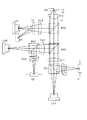
図1は、本願発明に関わる光ピックアップ装置を示す模式図である。
レーザーダイオードLD1は、第1光源であり、波長λ1が405nmの青紫色レーザーが用いられるが、波長が390nm〜420nmである範囲のものを適宜採用することができる。LD2は、第2光源であり、波長λ2が655nmの赤色レーザーが用いられるが、波長が630nm〜680nmである範囲のものを適宜採用することができる。LD3は、第3光源であり、波長λ3が780nmの赤外レーザーが用いられるが、波長が750nm〜800nmである範囲のものを適宜採用することができる。
【0028】
ビームスプリッタBS1はLD1から入射する光源を対物光学素子であるOBLの方向へ透過させるが、光ディスク(第1光情報記録媒体)からの反射光(戻り光)について、センサーレンズ群SL1を経て受光センサーS1に集光させる機能を有する。BS2も機能は同様である。
【0029】
BS3はLD1からの光束と、LD2からの光束とを同一の光路に載せるために配置される。またBS4は、LD3からの光束と、BS3からの光束とを同一の光路に載せるために配置される。
【0030】
LD1から投光された光束は、BS1を経て、コリメータCL1に入射し、これによって無限平行光にコリメートされたのち、BS3、BS4を経て対物光学素子である対物レンズOBLに入射する。そして第1光情報記録媒体の保護基板を介して情報記録面上に集光スポットを形成する。情報記録面上で反射したのち、同じ経路をたどって、コリメータCL1を通過してから、BS1によってセンサーレンズSL1を経てセンサーS1に集光する。このセンサーによって光電変換され、電気的な信号となる。
【0031】
LD2から投光された光束も、同様に光ディスク(第2光情報記録媒体)に集光スポットを形成し、反射して最終的にセンサーS2に集光する。
ちなみにLD3から投光された光束についても同様であるが、この例ではビームスプリッタの代わりに回折板DPを設ける事により、センサーS3へ戻り光が集光するようになっている。CDからの情報の再生を行う場合は、DVDや「高密度な光ディスク」に比べて受光する光量が少なくても良いので、このような構成を採用することができる。
【0032】
なお対物光学素子OBLは、この図では単一のレンズであるが、必要に応じて複数の光学素子から構成されるようにしてもよい。また材質はプラスティック樹脂でもよいし、ガラスでも良い。
【0033】
またLD1から投光された光束、LD2から投光された光束が光ディスクD1、D2の保護基板を介して情報記録面に集光する状態が、OBLの光軸左側に描かれており、LD3から投光された光束が光ディスクD3の保護基板を介して情報記録面に集光する状態が、OBLの光軸右側に描かれている。このように、再生/記録する光ディスクによって、基本的な位置が図示しないアクチュエーターによって切り替わり、その基準位置からピント合わせ(フォーカシング)を行う。
【0034】
そして各々の光情報記録媒体の保護基板厚、さらにピットの大きさにより、対物光学素子OBLに要求される開口数も異なる。ここでは、CD用の開口数は0.45、DVDおよび「高密度な光ディスク」の開口数は0.65としている。ただし、CDについては0.43〜0.50、DVDについては0.58〜0.68の範囲で適宜選択可能である。
【0035】
なおIRは不要光をカットするための絞りである。
さて本実施例では、「第1光源、前記第2光源及び前記第3光源の共通光路に配置され、回折構造を有する回折光学素子」の役割を、対物光学素子OBLに持たせている。そのため、対物光学素子に鋸歯状の回折構造を設けている。
【0036】
そしてこの鋸歯のピッチ(回折パワー)や深さ(ブレイズド化波長)を設定することにより、「高密度な光ディスク」に対しては、第1光源からの光束が2次回折光による集光スポットとして形成され、DVDに対しては、第2光源からの光束が1次回折光による集光スポットとして形成されるようになっている。
【0037】
このように、回折次数が異なる光を利用することにより、各々の場合における回折効率を高くすることができ、光量を確保することができる。
まだCDに対しては、第3光源からの光束を、DVDと同じ次数の回折光にすることが好ましいが、これは適宜他の次数になるようにしても良い。この例では、DVDと同じ1次の回折光として集光スポットを形成するようにしている。
【0038】
この例では、回折光学素子として、回折構造を対物光学素子に設けた例を説明したが、請求項3や4のように、このような異次回折光を生じる回折構造をコリメータに設けても良いし、また別の光学素子を光路中に設けることも可能である。
【0039】
また上記した開口の切り替えについても、回折光学素子を始めとして、公知の技術を適用することができる。
なお上記の実施例では、情報の再生について説明してきたが、情報の記録においても基本的な構成・光学的作用は変わらず、光情報記録媒体の記録面に集光スポットを形成することにより、記録層に熱化学変化を生ぜしめて、記録を行う。
【0040】
また、温度補償及び/又は色収差補償を行うための光学的補正構造を有する光学素子を、必要に応じて光路中に設ける事ができるのはいうまでもない。そしてこれらの光学的補正構造は回折構造や位相差付与構造によって実現できるし、対物光学素子、コリメータ及びその他の素子に設けることが出来る。
(第2の実施の形態)
同じく図1を用いて、請求項5の発明について説明する。
【0041】
各光学素子に関して、第1の実施の形態と同じ機能については説明を省略する。
この実施例では、第1互換光学素子の役割を、対物光学素子OBLに持たせている。そして第2互換光学素子の役割をコリメータCL3に持たせている。
【0042】
つまり、第1互換光学素子である対物光学素子OBLは、全ての光源が通過する光路に配置されており、第2互換光学素子であるコリメータCL3は、第3光源のみが通過する光路に配置される。
【0043】
さて第1互換光学素子である対物光学素子OBLは、回折構造を有していて、それによって「高密度な光ディスク」およびDVD間の互換(第1互換機能)を達成する。
【0044】
具体的には、第1光源と第2光源との間の波長差に基づく球面収差を補正する。また、回折構造で無くとも、位相差付与構造を用いても、同様の光学的作用を得る事が出来る。
【0045】
なお、光情報記録媒体について、保護基板の厚さが異なると、その差にもとづく球面収差が発生するが、ここでは「高密度な光ディスク」とDVDとは共に同じ0.6mmの保護基板を用いているので、そのような基板厚差に基づく球面収差は生じない。
【0046】
第2互換光学素子であるコリメータCL3にも回折構造が設けられている。これは先の対物光学素子OBLの回折構造と組み合わされることにより、「高密度な光ディスク」およびCD間の互換、さらにDVDおよびCD間の互換(第2互換機能)を達成する。
【0047】
具体的には、「高密度な光ディスク」およびCD間の互換についてみると、使用波長も保護基板の厚さも異なる事から、第1光源と第3光源との間の波長差に基づく球面収差と、保護基板厚差(0.1mmと1.2mm)に基づく球面収差の両方を補正する。
【0048】
DVDおよびCD間の互換についても同様で、第2光源と第3光源との間の波長差に基づく球面収差と、保護基板厚差(0.6mmと1.2mm)に基づく球面収差の両方を補正する。
【0049】
これにより、各光情報記録媒体に対して、好適な集光スポットを形成することができる。
また先の実施の形態と同様に、異なった回折次数の回折光による集光スポットが形成されるようにしているので、「高密度な光ディスク」、DVDについて、光量を確保し、確実な情報の記録及び/又は再生が可能になる。
【0050】
この実施例では、第2互換光学素子として、コリメータCL3に回折光学素子を設けた例(請求項9)を示したが、他にも、たとえば波長選択性のあるダイクロイックフィルタや、電気的に光学的作用を切り替えることが出来る液晶素子を用いても、同様の光学的作用を得ることが出来る(請求項7、8)。特に液晶素子は、屈折率を変化させることができるという作用があるため、動的な制御が可能である。
【0051】
また他にも、第1互換機能、第2互換機能については、位相差付与構造を設ける事によっても達成できる。
(第3の実施の形態)
この実施例は請求項11の発明に対応するもので、図1の構成から所定のコリメータのかわりにカップリングレンズを設けた光ピックアップ装置である。具体的には、コリメータCL1〜CL3のかわりにカップリングレンズCo1〜3を設ける。
【0052】
光源からの入射光を平行光にコリメートするコリメータを設けないため、有限発散光が対物光学素子に入射する。カップリングレンズはコリメータほどのパワーを有しないので、小型であり、このような構成にすることにより、ピックアップ装置を小型にすることができる。
【0053】
このように、無限平行光でなく、有限発散光を用いることにより、対物光学素子OBLに入射する光束の倍率が変わるので、これによって波長差に基づく球面収差及び基板厚差に基づく球面収差を補正することができることが知られているが、それでも十分な補正が出来ない場合がある。
【0054】
また有限光を用いることにより、温度特性が劣化するという問題もあるし、入射光束の倍率の差に基づく球面収差が発生するため、これを解消する必要がある。
【0055】
そこでこの実施例では、対物光学素子OBLに、波長毎にそれぞれ異なる倍率の光束を入射させるが、第1互換光学素子、第2互換光学素子によって、波長差に基づく球面収差、保護基板厚差に基づく球面収差及び光束の倍率差に基づく球面収差を補正するようにしている。
【0056】
第1互換素子は、第2の実施の形態と同じく、対物光学素子に回折光学素子を設けたものであり、第2互換光学素子は、カップリングレンズCo3に回折光学素子を設けたものである。
【0057】
これによって、第1光源乃至第3光源からの光束は、全て有限発散光で対物光学素子OBLに入射するが、球面収差を全て補正され、好適な集光スポットを形成する。
【0058】
ここではすべての光源について、無限発散光で対物光学素子OBLに入射するようにしてあるが、どれか一つの光源をそのようにしてもよく、また別の光源については無限平行光が入射するようにしてもよい。
(第4の実施の形態)
図2を用いて、請求項1の発明の、別の実施の形態について説明する。同じ符号を付しているものは、基本的には第1の実施の形態と同じ機能を有するが、異なるものについて説明する。なお光学的な作用についても殆ど同じである。
【0059】
この例では、光源を2つのユニットによって構成している。具体的には、図2のLD2'は、第2の光源(DVD用の光源)、第3の光源(CD用の光源)について、同一のパッケージに収めた、いわゆる2レーザー1パッケージの光源ユニットを用いている。
【0060】
このパッケージのうち、第2の光源を光軸上に位置するように調整するので、第3の光源については光軸上からやや離れた処に位置するため、像高が生じてしまうが、この特性を改善するための技術も既に知られており、それらの技術を必要に応じて適用できる。ここでは補正板DPを用いることによりその補正を行っている。補正板DPにはグレーティングが形成されており、それによって光軸からのズレを補正すると共に、センサーS2への集光にも寄与する。
【0061】
なおLD2'から実線で描かれているのがDVD用の光源光束であり、点線で描かれているのがCD用の光源光束である。
BS2はLD1からの光束と、LD2'からの光束とを同一の光路に載せるために配置される。またBS3は、LD2'からの光束をセンサーレンズSL2に入射させるために配置される。
【0062】
LD1から投光された光束は、BS1を経て、コリメータCL1に入射し、これによって無限平行光にコリメートされたのち、BS2を経て対物光学素子である対物レンズOBLに入射する。そして第1光情報記録媒体の保護基板を介して情報記録面上に集光スポットを形成する。情報記録面上で反射したのち、同じ経路をたどって、コリメータCL1を通過してから、BS1によってセンサーレンズSL1を経てセンサーS1に集光する。このセンサーによって光電変換され、電気的な信号となる。
【0063】
LD2'から投光された光束も、同様に光ディスク(第2光情報記録媒体または第3光情報記録媒体)に集光スポットを形成し、反射して最終的にセンサーS2に集光する。
【0064】
さて本実施例では、「第1光源、前記第2光源及び前記第3光源の共通光路に配置され、回折構造を有する回折光学素子」の役割を、対物光学素子OBLに持たせている。そのため、対物光学素子に鋸歯状の回折構造を設けている。
【0065】
そしてこの鋸歯のピッチ(回折パワー)や深さ(ブレイズド化波長)を設定することにより、「高密度な光ディスク」に対しては、第1光源からの光束が2次回折光による集光スポットとして形成され、DVDに対しては、第2光源からの光束が1次回折光による集光スポットとして形成されるようになっている。
【0066】
このように、回折次数が異なる光を利用することにより、各々の場合における回折効率を高くすることができ、光量を確保することができる。
まだCDに対しては、第3光源からの光束を、DVDと同じ次数の回折光にすることが好ましいが、これは適宜他の次数になるようにしても良い。この例では、DVDと同じ1次の回折光として集光スポットを形成するようにしている。
【0067】
この例では、回折光学素子として、回折構造を対物光学素子に設けた例を説明したが、請求項3や4のように、このような異次回折光を生じる回折構造をコリメータCL1に設けても良いし、また別の光学素子を光路中に設けることも可能である。
【0068】
また上記した開口の切り替えについても、回折光学素子を始めとして、公知の技術を適用することができる。
なお上記の実施例では、情報の再生について説明してきたが、情報の記録においても基本的な構成・光学的作用は変わらず、光情報記録媒体の記録面に集光スポットを形成することにより、記録層に熱化学変化を生ぜしめて、記録を行う。
【0069】
また、温度補償及び/又は色収差補償を行うための光学的補正構造を有する光学素子を、必要に応じて光路中に設ける事ができるのはいうまでもない。そしてこれらの光学的補正構造は回折構造や位相差付与構造によって実現できるし、対物光学素子、コリメータ及びその他の素子に設けることが出来る。
(第5の実施の形態)
同じく図2を用いて、請求項5の発明の、別の実施の形態について説明する。
【0070】
各光学素子に関して、第4の実施の形態と同じ機能については説明を省略する。
この実施例では、第1互換光学素子の役割を、対物光学素子OBLに持たせている。そして第2互換光学素子の役割をコリメータCL2に持たせている。
【0071】
つまり、第1互換光学素子である対物光学素子OBLは、全ての光源が通過する光路に配置されており、第2互換光学素子であるコリメータCL2は、第2光源と第3光源とが通過する光路に配置される。
【0072】
さて第1互換光学素子である対物光学素子OBLは、回折構造を有していて、それによって「高密度な光ディスク」に必要な集光スポットの形成に寄与する。
具体的には、第1光源と第2光源との間の波長差に基づく球面収差、第1光源と第3光源との間の波長差に基づく球面収差を補正する。さらに、「高密度な光ディスク」とCDとの保護基板厚差に基づく球面収差を補正する。
【0073】
また、回折構造で無くとも、位相差付与構造を用いても、同様の光学的作用を得る事が出来る。
なお、光情報記録媒体について、保護基板の厚さが異なると、その差にもとづく球面収差が発生するが、ここでは「高密度な光ディスク」とDVDとは共に同じ0.6mmの保護基板を用いているので、基板厚差に基づく球面収差は生じない。
【0074】
第2互換光学素子であるコリメータCL2にも回折構造が設けられている。これは先の対物光学素子OBLの回折構造と組み合わされることにより、DVDおよびCD間の互換(第2互換機能)を達成する。
【0075】
DVDおよびCD間の互換についてみると、使用波長も保護基板の厚さも異なる事から、第2光源と第3光源との間の波長差に基づく球面収差と、保護基板厚差(0.6mmと1.2mm)に基づく球面収差の両方を補正する。
【0076】
これにより、各光情報記録媒体に対して、好適な集光スポットを形成することができる。
また先の実施の形態と同様に、異なった回折次数の回折光による集光スポットが形成されるようにしているので、「高密度な光ディスク」、DVDについて、光量を確保し、確実な情報の記録及び/又は再生が可能になる。
【0077】
この実施例では、第2互換光学素子として、コリメータCL2に回折光学素子を設けた例(請求項9)を示したが、他にも、たとえば波長選択性のあるダイクロイックフィルタや、電気的に光学的作用を切り替えることが出来る液晶素子を用いても、同様の光学的作用を得ることが出来る(請求項7、8)。特に液晶素子は、屈折率を変化させることができるという作用があるため、動的な制御が可能である。
【0078】
また他にも、第1互換機能、第2互換機能については、位相差付与構造を設ける事によっても達成できる。
(第6の実施の形態)
この実施例は請求項11の発明に対応する別の実施例で、図2の構成から所定のコリメータのかわりにカップリングレンズを設けた光ピックアップ装置である。具体的には、コリメータCL1、CL2のかわりにカップリングレンズCo1、2を設ける。
【0079】
光源からの入射光を平行光にコリメートするコリメータを設けないため、有限発散光が対物光学素子に入射する。カップリングレンズはコリメータほどのパワーを有しないので、小型であり、このような構成にすることにより、ピックアップ装置を小型にすることができる。
【0080】
このように、無限平行光でなく、有限発散光を用いることにより、対物光学素子OBLに入射する光束の倍率が変わるので、これによって波長差に基づく球面収差及び基板厚差に基づく球面収差を補正することができることが知られているが、それでも十分な補正が出来ない場合がある。
【0081】
また有限光を用いることにより、温度特性が劣化するという問題もあるし、入射光束の倍率の差に基づく球面収差が発生するため、これを解消する必要がある。
【0082】
そこでこの実施例では、対物光学素子OBLに、波長毎にそれぞれ異なる倍率の光束を入射させるが、第1互換光学素子、第2互換光学素子によって、波長差に基づく球面収差、保護基板厚差に基づく球面収差及び光束の倍率差に基づく球面収差を補正するようにしている。
【0083】
第1互換素子は、第5の実施の形態と同じく、対物光学素子に回折光学素子を設けたものであり、第2互換光学素子は、カップリングレンズCo2に回折光学素子を設けたものである。
【0084】
これによって、第1光源乃至第3光源からの光束は、全て有限発散光で対物光学素子OBLに入射するが、球面収差を全て補正され、好適な集光スポットを形成する。
【0085】
ここではすべての光源について、無限発散光で対物光学素子OBLに入射するようにしてあるが、どれか一つの光源をそのようにしてもよく、また別の光源については無限平行光が入射するようにしてもよい。
(第6の実施の形態)
次に図3を用いて、請求項16または17の発明について説明する。
【0086】
各光学素子に関して、第1〜第5の実施の形態と同じ機能については説明を省略する。
対物光学素子である単玉プラスチックレンズOBLは、レンズホルダLHによって液晶素子LCDと一体化されている。ACはアクチュエータであり、レンズホルダLHを保持して、フォーカシングなどのために、光軸方向に移動させることが可能である。
【0087】
なお単玉プラスチックレンズOBLの光学機能面には回折構造が設けられており、請求項でいうところの回折光学素子に相当する。
またここではプラスチック製の単玉レンズであるが、2枚以上の複数玉を組み合わせたものでも良いし、ガラス製のレンズであっても良い。
【0088】
液晶素子LCDには、光軸対称なパターンが設けられており、電気的な通電状態を変化させることにより、入射する光束に対する光学的作用を切り替える事ができるようになっている。これは請求項でいうところの互換光学素子に相当する。
【0089】
この液晶素子に、各コリメータによって無限平行光とされた光束が入射するように構成されている。
無限平行光を利用する光学系には、様々な利点があるが、反面、集光スポット形成に影響する低次の収差が生じるという欠点がある。そのため、対物光学素子のみで3種類の光情報記録媒体に対応することは難しい。
【0090】
そこで請求項16の発明では、回折面をそなえた対物光学素子は、第1光情報記録媒体である「高密度な光ディスク」に対して、対物光学素子単独で使用可能であるかわりに、他の情報記録媒体に対しては不十分な性能(情報の再生および/または記録のために十分な集光スポットの形成ができない性能)であるように回折構造や非球面を設計する。
【0091】
そしてこれとは別の互換光学素子(液晶素子)を用意し、これと対物光学素子とを組み合わせる事により、対物光学素子において不十分であった点を補い、第2光情報記録媒体(DVD)及び第3光情報記録媒体(CD)に対して情報の再生および/または記録のために十分な集光スポットの形成ができるようにする。
【0092】
なお、対物光学素子は、第2光情報記録媒体(DVD)に用いる波長λ2(655nm)の光束、第3光情報記録媒体(CD)に用いる波長λ3(780nm)の光束に対しては、不十分な性能とはいえ、出来る限り回折光率が高く、液晶素子による補正の負荷を低減するためにも、波長λ1(405nm)の光束とは別の次数の回折光を利用する。
【0093】
また請求項17の発明では、回折面をそなえた対物光学素子の設計を工夫し、第1光情報記録媒体(高密度な光ディスク)の他、第2光情報記録媒体(DVD)又は第3光情報記録媒体(CD)のいずれか一方の、2種類の光情報記録媒体に対して、対物光学素子単独で使用可能であるように、回折構造や非球面を設計する。そして、残りの1種類の光情報記録媒体に対して、対物光学素子の光学的作用に別の互換光学素子(液晶素子)の光学的作用を重畳することにより、情報の再生および/または記録のために十分な集光スポットの形成ができるようにする。
【0094】
以上の通り、液晶素子である互換光学素子は、波長λ1の光束に対しては光学的作用を生じず、必要に応じて波長λ2の光束および/または波長λ3の光束に対して光学的作用を生じる。
【0095】
なお、レンズホルダLHによって一体に保持された対物光学素子と液晶素子とをまとめて、対物光学素子としてみなすことも可能であり、本実施の形態は請求項1の発明の応用例であるともいえる。
【0096】
ここで述べてきた回折構造としては、鋸歯状のものの他、所定段数の階段形状を周期的に繰り返した形状である、いわゆるマルチレベル構造のものを採用することもできる。
【0097】
また回折構造によって発生する回折光の次数については、必要に応じて様々な組合せを用いることが可能である。
請求項16の発明の場合は、以下のような次数の組合せを選択することが好ましい。なおkは波長λ1の光束に対して生じる回折光の次数、mは波長λ2の光束に対して生じる回折光の次数、nは波長λ3の光束に対して生じる回折光の次数である。
【0098】
イ)k=1、m=0、n=2
ロ)k=2、m=1、n=1
ハ)k=2、m=1、n=0
ニ)k=2、m=2、n=1
ホ)k=3、m=2、n=2
ヘ)k=4、m=3、n=2
ト)k=5、m=3、n=2
チ)k=5、m=3、n=3
リ)k=6、m=4、n=3
ヌ)k=7、m=4、n=4
ル)k=8、m=5、n=4
請求項17の発明の場合であって、対物光学素子で第1光情報記録媒体と第2光情報記録媒体との互換を行ない、液晶素子を組み合わせて第3光情報記録媒体との互換を図る場合も、上記と同じ次数の組合せが好ましい。
【0099】
また、請求項17の発明の場合であって、対物光学素子で第1光情報記録媒体と第2光情報記録媒体との互換を行ない、液晶素子を組み合わせて第3光情報記録媒体との互換を図る場合は、λ1とλ3の波長がほぼ2倍の関係となっていることから、k:nが2:1となっている場合は、ほぼ同じ回折作用を生じてしまうため、採用できない。したがって上記の(イ)から(ル)の組合せのうち、k:nが2:1となっている場合を除外した、次の組合せを採用することが好ましい。
【0100】
イ)k=1、m=0、n=2
ハ)k=2、m=1、n=0
ホ)k=3、m=2、n=2
ト)k=5、m=3、n=2
チ)k=5、m=3、n=3
ヌ)k=7、m=4、n=4
(第7の実施の形態)
次に図4を用いて、請求項16または17の発明の別の実施の形態について説明する。
【0101】
これは液晶素子LCDのかわりに、光軸方向に移動可能なビームエキスパンダーBEを備えたものである。
このビームエキスパンダーは独自のアクチュエータを備えており、光軸方向に移動することが可能になっている。これによって球面収差補正を行なう。
【0102】
実際に使用する場合は、使用する光源光束に応じて、光軸方向に進退させることにより球面収差補正を行ない、対応する光情報記録媒体に対して良好な集光スポットを形成する。
【0103】
回折光学素子である対物レンズとその作用については、第6の実施の形態と同じであり、少なくとも第1光情報記録媒体に対しては単独で良好な集光スポットを形成することができる。第2光情報記録媒体、第3光情報記録媒体に対しては十分な集光スポット形成性能を有しないか、あるいは片方についてのみ、集光スポットの形成が可能である。
【0104】
またそのために、波長毎に異なった次数の回折光が生じるようにされている。
互換光学素子であるビームエキスパンダーは、上述の通り光軸方向に進退可能であるので、これによって球面収差の補正が可能である。そこで、対物光学素子で不十分な点を補い、第2光情報記録媒体および/または第3光情報記録媒体に対して良好な集光スポット形成が可能になる。
【0105】
なお、光学要素の大型化につながるが、ビームエキスパンダーと対物光学素子とを一体化させる構成もありうる。この場合は、第3光情報記録媒体に対する収差補正の観点からは好ましい。
【0106】
【発明の効果】
以上、本発明に関わる光ピックアップ装置によれば、3つのフォーマットの光ディスクに対して互換の光ピックアップ装置を実現することができる。またコンパクトな構成であり、光量も確保されるので、性能上も好適である。
【図面の簡単な説明】
【図1】本発明に関わる光ピックアップ装置の図である。
【図2】本発明に関わる、別の態様の光ピックアップ装置の図である。
【図3】本発明に関わる、別の態様の光ピックアップ装置の図である。
【図4】本発明に関わる、別の態様の光ピックアップ装置の図である。
【符号の説明】
LD1 第1光源
LD2 第2光源
LD3 第3光源
LD2' 第2光源(2波長1パッケージ)
S1 センサー
S2 センサー
S3 センサー
S2' センサー
SL1 センサーレンズ
SL2 センサーレンズ
SL3 センサーレンズ
DP 回折板
BS1 ビームスプリッタ
BS2 ビームスプリッタ
BS3 ビームスプリッタ
BS4 ビームスプリッタ
CL1 コリメータ
CL2 コリメータ
CL3 コリメータ
IR 絞り
OBL 対物光学素子
D1 光ディスク(「高密度な光ディスク」)
D2 光ディスク(DVD)
D3 光ディスク(CD)
AC アクチュエータ
LH レンズホルダ
LCD 液晶素子
BE ビームエキスパンダー[0001]
TECHNICAL FIELD OF THE INVENTION
The present invention relates to an optical pickup device and an objective optical element used for the optical pickup device, and more particularly, to an optical pickup device capable of complying with the standards of a plurality of optical information recording media (optical discs) and an optical pickup device. It relates to an objective optical element.
[0002]
[Prior art]
From the past to the present, the reproduction and recording of information on optical information recording media (also called optical disks or media) such as CDs (compact disks) and DVDs (digital video disks or digital versatile disks). An optical pickup device (also referred to as an optical head, an optical head device, and the like) for performing the operation has been developed and manufactured, and has been widely used.
[0003]
In recent years, research and development have also been carried out on standards for optical information recording media capable of recording information at a higher density.
In such an optical pickup device, a light beam emitted from a light source (mainly a laser diode is used) is converted into an optical disk through an optical system including optical elements such as a beam shaping prism, a collimator, a beam splitter, and an objective optical element. To form a spot by condensing the light on the information recording surface, and then condensing the reflected light from the information recording holes (also called pits) on the recording surface again on the sensor through the optical system, and converting it into an electric signal. The information is reproduced by the conversion. At this time, since the luminous flux of the reflected light also changes depending on the shape of the information recording hole, the information of "0" and "1" is distinguished using this. Note that a protective substrate (a protective layer made of plastic; also referred to as a cover glass) is provided on the information recording surface of the optical disc.
[0004]
When recording information on a recordable medium such as a CD-R or CD-RW, a spot is formed by a laser beam on a recording surface, and a thermochemical change occurs on a recording material on the recording surface. Thereby, for example, in the case of CD-R, the shape similar to the information recording hole is formed by the irreversible change of the thermal diffusible dye. In the case of CD-RW, since a phase change material is used, the information is reversibly changed between a crystalline state and an amorphous state by a thermochemical change, so that information can be rewritten.
[0005]
In an optical pickup device for reproducing information from a CD-standard optical disk, the NA of the objective lens is about 0.45, and the wavelength of the light source used is about 785 nm. For recording, about 0.50 is often used. The thickness of the protective substrate of the optical disk of the CD standard is 1.2 mm.
[0006]
Now, CDs have become widespread as optical information recording media, but DVDs have become widespread in recent years. This is to increase the information recording amount by making the protective substrate thinner and making the information recording hole smaller than the CD. The CD is about 600 to 700 MB (megabyte), whereas about 4 to 4 MB. It has a large recording capacity of 0.7 GB (gigabyte) and is often used as a distribution medium that records moving images such as movies.
[0007]
An optical pickup device for reproducing information from a DVD-standard optical disk is in principle the same as that for a CD, but the information recording hole is small as described above. Is about 0.60, and the wavelength of the light source used is about 655 nm. For recording, about 0.65 is often used. The thickness of the protective substrate of the DVD standard optical disk is 0.6 mm.
[0008]
As for optical discs of the DVD standard, recordable optical discs have already been put into practical use, and there are various standards such as DVD-RAM, DVD-RW / R, and DVD + RW / R. The technical principle regarding these is also the same as in the case of the CD standard.
[0009]
As described above, optical disks with higher density and higher capacity are being proposed.
In this method, a so-called blue-violet laser light source having a wavelength of about 405 nm is mainly used as a light source.
[0010]
Regarding such a “high-density optical disk”, even if the wavelength to be used is determined, the thickness of the protective substrate, the storage capacity, the NA, etc. are not uniformly determined.
If the direction in which the recording density is significantly improved is selected, the thickness of the protective substrate of the optical disk is reduced, and accordingly, the NA is increased. Conversely, the thickness and NA of the protective substrate can be the same as the standard of a conventional optical disk such as a DVD. In this case, the physical recording density does not increase significantly, but the performance required as an optical system becomes relatively moderate.
[0011]
Specifically, the thickness of the protective substrate has been proposed to be 0.1 mm or thinner, or 0.6 mm which is the same as that of DVD.
The plurality of standards for such a “high-density optical disk” are in principle the same as CDs and DVDs, but if the thickness of the protective substrate is different, the size of the information recording hole will also be different. Even if a light source having the same wavelength is used, it is not possible to simply read and record information using the same optical pickup device.
[0012]
In order to achieve “high-density optical disc” and “compatibility” that can reproduce and record information with respect to multiple existing standards using a single optical pickup device including an objective optical element, Problem must be solved.
(1) Since a suitable NA differs for each optical disc, a “aperture” function for selectively using each NA according to the medium is required.
(2) Spherical aberration occurs between optical disks having different protective substrate thicknesses due to the difference, and it is necessary to eliminate this. Particularly, since DVD is 0.6 mm and CD is 1.2 mm, very remarkable spherical aberration occurs. When the protective substrate thickness of the “high-density optical disk” is set to 0.1 mm, it is necessary to further correct spherical aberration.
[0013]
Regarding these problems, a method of using a dichroic filter having wavelength selectivity and a method of providing wavelength selectivity by providing a diffraction structure or an optical path difference providing structure in an objective optical element have been proposed and realized. A method of dividing the objective optical element into a special annular zone structure has also been proposed.
[0014]
There are also the following issues.
(3) When trying to achieve “compatibility” between optical disc standards having different protection wavelengths and the same NA (including substantially the same case) (for example, when using 655 nm and 405 nm), Although spherical aberration does not occur due to the difference in the thickness of the protective substrate, generation of spherical aberration (= spherical aberration corresponding to chromatic aberration) due to the wavelength difference is unavoidable and needs to be eliminated.
(4) Even if the light beams incident on the objective optical element have different wavelengths, if they are all collimated infinite parallel light, spherical aberration based on the difference in magnification does not occur, but finite light (divergent light / convergent light) ), A magnification difference occurs, and spherical aberration based on this difference occurs.
(5) Attempting to achieve “compatibility” with a single optical pickup device for the three formats of CD, DVD, and “high-density optical disk” is more difficult than performing “compatibility” between the two formats. Complicated spherical aberration correction must be performed. In other words, it was only necessary to perform the correction between the CD and the DVD, between the "CD and the DVD", "between the CD and the" high-density optical disk "", and "between the DVD and the" high-density optical disk "". Needs to be corrected.
[0015]
[0016]
However, there is no disclosure or suggestion of a technology corresponding to three types of formats as in the present invention.
[0017]
[Patent Document 1]
JP 2001-93179 A
[0018]
[Problems to be solved by the invention]
As described above, conventionally, regarding "interchangeability" between different optical discs, a method of using a dichroic filter having wavelength selectivity and a method of providing wavelength selectivity by providing a diffraction structure in an objective optical element have been proposed and realized. Have been.
[0019]
However, giving various optical functions to the objective optical element is suitable for reducing the number of parts, reducing cost and size, but may not achieve optical performance.
[0020]
In the case where compatibility is to be achieved for the three formats, which are to be solved this time, the number of objects to be corrected increases, so that it cannot be solved simply by adopting the above method.
[0021]
Further, depending on the magnification of the light beam incident on the objective optical element, spherical aberration may occur, and it is necessary to eliminate it.
In addition, since the optical pickup device itself is required to be reduced in size and weight, and particularly reduced in thickness, extremely strict performance is required for element parts, particularly optical elements.
[0022]
In particular, by reducing the thickness, the working distance (the distance between the objective optical element and the optical disk; also referred to as the working distance) is reduced. Increasing the magnification and increasing the working distance is not preferable because the image height characteristics are deteriorated. When the difference in working distance increases, the load on the actuator increases, and the power consumption also increases.
[0023]
Accordingly, an object of the present invention is to provide a compact objective optical element or an optical pickup device which can achieve compatibility between three formats and satisfy required performance and specifications.
[0024]
[Means for Solving the Problems]
(1) Information is reproduced and / or recorded on a first optical information recording medium having a protective substrate thickness t1 using a light beam emitted from a first light source having a wavelength λ1, and a protective substrate thickness t2 (t1 ≦ t2) is obtained. The information is reproduced and / or recorded on the second optical information recording medium using the light flux emitted from the second light source having the wavelength λ2 (λ1 <λ2), and the protective substrate thickness t3 (t2 <t3). An optical pickup device for reproducing and / or recording information on a third optical information recording medium using a light beam emitted from a third light source having a wavelength λ3 (λ2 <λ3), wherein the first light When reproducing and / or recording information from / to the information recording medium, the second optical information recording medium and the third optical information recording medium, infinite parallel light is applied to an objective optical element included in the optical pickup device. A light beam is incident, and the light The up device includes a diffractive optical element having a diffractive structure, which is disposed on a common optical path of the first light source, the second light source, and the third light source, and is provided on the first optical information recording medium by the diffractive optical element. A condensed spot is formed by the generated m-th (m is a natural number) order diffracted light, and the n-th (n is a natural number that is n ≠ m) -order diffracted light generated by the diffractive optical element on the second optical information recording medium. An optical pickup device characterized in that a converging spot is formed by the method.
(2) The optical pickup device according to (1), wherein the diffractive optical element is the objective optical element.
(3) The optical pickup device according to (1), wherein the diffractive optical element is a collimator.
(4) The optical pickup device according to (1), wherein the diffractive optical element is an optical element provided separately from the objective optical element and the collimator.
(5) Information is reproduced and / or recorded on the first optical information recording medium having the protective substrate thickness t1 using the light beam emitted from the first light source having the wavelength λ1, and the protective substrate thickness t2 (t1 ≦ t2) is obtained. The information is reproduced and / or recorded on the second optical information recording medium using the light flux emitted from the second light source having the wavelength λ2 (λ1 <λ2), and the protective substrate thickness t3 (t2 <t3). An optical pickup device for reproducing and / or recording information on the third optical information recording medium by using a light beam emitted from a third light source having a wavelength λ3 (λ2 <λ3), wherein the optical pickup device Is a first compatible optical element disposed on a common optical path of the first light source, the second light source, and the third light source, and one of the first light source, the second light source, and the third light source. Arranged in the optical path of only the light source or in the common optical path of some two light sources A second compatible optical element, wherein the first compatible optical element includes at least one of the first optical information recording medium, the second optical information recording medium, and the third optical information recording medium. The information recording medium has a first compatible function of forming a condensed spot necessary for reproducing and / or recording information, and the second compatible optical element is combined with the first compatible optical element. Focusing on the other optical information recording medium of the first optical information recording medium, the second optical information recording medium, and the third optical information recording medium necessary for reproducing and / or recording information; The optical pickup device has a second compatibility function of forming a spot, and the optical pickup device includes a diffractive optical element arranged in a common optical path of the first light source, the second light source, and the third light source, and having a diffractive structure. With respect to the first optical information recording medium A condensed spot of m (m is a natural number) diffracted light generated by the diffractive optical element is formed, and n (n is a natural number satisfying n ≠ m) generated by the diffractive optical element on the second optical information recording medium. 3. An optical pickup device characterized in that a condensed spot by the next diffracted light is formed.
(6) The optical pickup device according to (5), wherein the first compatible optical element is an objective optical element.
(7) The optical pickup device according to (5), wherein the second compatible optical element is a dichroic filter.
(8) The optical pickup device according to any one of (5) and (6), wherein the second compatible optical element is a liquid crystal element.
(9) The optical pickup device according to any one of (5) and (6), wherein the second compatible optical element is a diffractive optical element.
(10) When reproducing and / or recording information from / to the optical information recording medium, all of the first optical information recording medium, the second optical information recording medium, and the third optical information recording medium are A light beam having the same magnification is incident on the objective optical element, and the first compatibility function and the second compatibility function correct spherical aberration based on a wavelength difference and spherical aberration based on a protective substrate thickness difference between optical information recording media. The optical pickup device according to any one of (5) to (9), wherein:
(11) When reproducing and / or recording information on the optical information recording medium, different magnifications are applied to the first optical information recording medium, the second optical information recording medium, and the third optical information recording medium. While the light beam is incident on the objective optical element,
The first compatibility function and the second compatibility function include a spherical aberration based on a wavelength difference, a spherical aberration based on a protective substrate thickness difference between optical information recording media, and a spherical aberration based on a magnification difference of a light beam incident on the objective optical element. The optical pickup device according to any one of (5) to (9), wherein
(12) The optical pickup device according to any one of (1) to (11), wherein m = 2.
(13) The optical pickup according to any one of (1) to (12), wherein n = 1.
(14) A condensed spot is formed on the third optical information recording medium by n-th order diffracted light generated by the diffractive optical element, (1) to (13). An optical pickup device according to
(15) The optical pickup device according to any one of (1) to (14), further including an optical correction structure for performing temperature compensation and / or chromatic aberration compensation.
(16) Information is reproduced and / or recorded on the first optical information recording medium having the protective substrate thickness t1 using the light beam emitted from the first light source having the wavelength λ1, and the protective substrate thickness t2 (t1 = t2 The information is reproduced and / or recorded on the second optical information recording medium using the light flux emitted from the second light source having the wavelength λ2 (λ1 <λ2), and the protective substrate thickness t3 (t2 <t3). An optical pickup device for reproducing and / or recording information on the third optical information recording medium by using a light beam emitted from a third light source having a wavelength λ3 (λ2 <λ3), wherein the optical pickup device Is disposed on a common optical path of the first light source, the second light source, and the third light source, and is disposed closer to the light source than the diffractive optical element, and can switch an optical action for each wavelength. A first optical information storage device comprising a compatible optical element; When performing reproduction and / or recording of information on the medium, the second optical information recording medium, and the third optical information recording medium, a beam of infinite parallel light is incident on the compatible optical element, The element forms a condensed spot sufficient to reproduce and / or record information on at least the first optical information recording medium, and the light beam of λ2 or the light beam of λ3 The compatible optical element generates diffracted light of a different order from the luminous flux of λ1, and the compatible optical element has an optical effect on the second optical information recording medium and the third optical information recording medium on the luminous flux of λ1. A different optical action is generated and combined with the optical action of the diffractive optical element to reproduce and / or record information on the second optical information recording medium and the third optical information recording medium. line Optical pickup device characterized by forming a sufficient focusing spot for.
(17) Information is reproduced and / or recorded on the first optical information recording medium having the protective substrate thickness t1 using the light flux emitted from the first light source having the wavelength λ1, and the protective substrate thickness t2 (t1 = t2 The information is reproduced and / or recorded on the second optical information recording medium using the light flux emitted from the second light source having the wavelength λ2 (λ1 <λ2), and the protective substrate thickness t3 (t2 <t3). An optical pickup device for reproducing and / or recording information on the third optical information recording medium by using a light beam emitted from a third light source having a wavelength λ3 (λ2 <λ3), wherein the optical pickup device Is disposed on a common optical path of the first light source, the second light source, and the third light source, and is disposed closer to the light source than the diffractive optical element, and can switch an optical action for each wavelength. A first optical information storage device comprising a compatible optical element; When performing reproduction and / or recording of information on the medium, the second optical information recording medium, and the third optical information recording medium, a beam of infinite parallel light is incident on the compatible optical element, The device is configured to diffract light of different orders with respect to the first optical information recording medium and one of the second optical information recording medium and the third optical information recording medium. Forming a condensing spot necessary for reproducing and / or recording information, and the compatible optical element optically transmits the λ1 light beam to the second optical information recording medium and the third optical information recording medium. An optical action different from the action is generated, and the other optical information recording medium of the second optical information recording medium and the third optical information recording medium is combined with the optical action of the diffractive optical element. Against the medium Distribution of reproduction and / or an optical pickup device characterized by forming a focused spot necessary for recording.
(18) The optical pickup device according to any one of (16) to (17), wherein the diffractive optical element is an objective optical element.
(19) The optical pickup device according to (18), wherein the objective optical element is a single ball.
(20) The optical pickup device according to (18), wherein the objective optical element is a plurality of balls.
(21) The optical pickup device according to any one of (16) to (20), wherein the compatible optical element does not cause an optical effect on the light beam of λ1.
(22) The optical pickup device according to any one of (16) to (20), wherein the compatible optical element is a liquid crystal element.
(23) The optical pickup device according to (22), wherein an energization state is changed depending on a wavelength of a light beam incident on the liquid crystal element to switch an optical function.
(24) The optical pickup device according to any one of (16) to (20), wherein the compatible optical element is a movable beam expander.
(25) The optical pickup device according to (24), wherein the beam expander is moved in an optical axis direction according to a wavelength of a light beam incident thereon to switch an optical function.
(26) The optical pickup according to any one of (16) to (25), wherein the diffractive optical element and the compatible optical element are integrally held and driven by one driving unit. apparatus.
(27) The optical pickup device according to any one of (16) to (26), wherein the diffraction surface has a multi-level structure.
(28) The diffractive optical element may form a condensed spot that is insufficient for reproducing and / or recording information on the second optical information recording medium and the third optical information recording medium. The optical pickup device according to any one of (16) and (18) to (27), which is characterized in that:
(29) The diffractive optical element generates k-th (k is a natural number) diffracted light with respect to the λ1 light beam, and m-th (m is a natural number with m ≠ k) -order diffraction with respect to the λ2 light beam. The optical pickup device according to (16), wherein light is generated, and n-th (n is a natural number that is n ≠ k) order diffracted light is generated with respect to the light beam of λ1.
(30) The optical pickup device according to (18), wherein m ≠ n.
(31) The optical pickup device according to (18), wherein m = n.
(32) The optical pickup device according to (30), wherein k = 1, m = 0, and n = 2.
(33) The optical pickup device according to (31), wherein k = 2, m = 1, and n = 1.
(34) The optical pickup device according to (30), wherein k = 2, m = 1, and n = 0.
(35) The optical pickup device according to (30), wherein k = 2, m = 2, and n = 1.
(36) The optical pickup device according to (31), wherein k = 3, m = 2, and n = 2.
(37) The optical pickup device according to (30), wherein k = 4, m = 3, and n = 2.
(38) The optical pickup device according to (30), wherein k = 5, m = 3, and n = 2.
(39) The optical pickup device according to (31), wherein k = 5, m = 3, and n = 3.
(40) The optical pickup device according to (30), wherein k = 6, m = 4, and n = 3.
(41) The optical pickup device according to (31), wherein k = 7, m = 4, and n = 4.
(42) The optical pickup device according to (30), wherein k = 8, m = 5, and n = 4.
(43) The diffractive optical element is a condensed spot necessary for reproducing and / or recording information on the first optical information recording medium and the second optical information recording medium by diffracted lights of different orders. The optical pickup device according to (17), further comprising a diffraction surface that forms
(44) The diffractive surface is provided on the entire optical function surface of the diffractive optical element, and is a diffractive surface for correcting spherical aberration based on a wavelength difference between the wavelength λ1 and the wavelength λ2. An optical pickup device according to item 43).
(45) The compatible optical element corrects a spherical aberration caused by a substrate thickness difference between the substrate thicknesses t1 and t3 and a spherical aberration based on a wavelength difference between the wavelengths λ1 and λ3. The optical pickup device according to any one of (44).
(46) The diffractive optical element generates k-th (k is a natural number) order diffracted light with respect to the λ1 light beam, and m-th (m is a natural number with m ≠ k) -order diffraction light with respect to the λ2 light beam. The optical pickup according to any one of (43) to (45), wherein light is generated, and n-th (n is a natural number that is n ≠ k) -order diffracted light is generated with respect to the light beam of λ1. apparatus.
(47) The optical pickup device according to (46), wherein m ≠ n.
(48) The optical pickup device according to (46), wherein m = n.
(49) The optical pickup device according to (47), wherein k = 1, m = 0, and n = 2.
(50) The optical pickup device according to (48), wherein k = 2, m = 1, and n = 1.
(51) The optical pickup device according to (47), wherein k = 2, m = 1, and n = 0.
(52) The optical pickup device according to (47), wherein k = 2, m = 2, and n = 1.
(53) The optical pickup device according to (48), wherein k = 3, m = 2, and n = 2.
(54) The optical pickup device according to (47), wherein k = 4, m = 3, and n = 2.
(55) The optical pickup device according to (47), wherein k = 5, m = 3, and n = 2.
(56) The optical pickup device according to (48), wherein k = 5, m = 3, and n = 3.
(57) The optical pickup device according to (47), wherein k = 6, m = 4, and n = 3.
(58) The optical pickup device according to (48), wherein k = 7, m = 4, and n = 4.
(59) The optical pickup device according to (47), wherein k = 8, m = 5, and n = 4.
(60) The diffractive optical element forms a condensed spot necessary for reproducing and / or recording information on the first optical information recording medium and the third optical information recording medium by using diffracted lights of different orders. The optical pickup device according to (17), having a diffraction surface to be formed.
(61) The diffractive surface is provided in a predetermined region of the optical function surface of the diffractive optical element. The diffractive surface has a spherical aberration caused by a difference in substrate thickness between the substrate thicknesses t1 and t3, and the wavelengths λ1 and λ3. The optical pickup device according to (60), which is a diffractive surface that corrects spherical aberration based on a wavelength difference between the optical pickup and the optical pickup.
(62) The optical pickup device according to any one of (60) to (61), wherein the compatible optical element corrects a spherical aberration based on a wavelength difference between the wavelength λ1 and the wavelength λ2.
(63) The diffractive optical element generates k-th (k is a natural number) -order diffracted light with respect to the λ1 light beam, and m-th (m is a natural number with m ≠ k) -order diffraction light with respect to the λ2 light beam. The optical pickup according to any one of (60) to (62), wherein light is generated, and diffracted light of order n (n is a natural number that is n ≠ k) is generated with respect to the light beam of λ1. apparatus.
(64) The optical pickup device according to (63), wherein m ≠ n.
(65) The optical pickup device according to (63), wherein m = n.
(66) The optical pickup device according to (64), wherein k = 1, m = 0, and n = 2.
(67) The optical pickup device according to (64), wherein k = 2, m = 1, and n = 0.
(68) The optical pickup device according to (65), wherein k = 3, m = 2, and n = 2.
(69) The optical pickup device according to (64), wherein k = 5, m = 3, and n = 2.
(70) The optical pickup device according to (65), wherein k = 5, m = 3, and n = 3.
(71) The optical pickup device according to (65), wherein k = 7, m = 4, and n = 4.
[0025]
BEST MODE FOR CARRYING OUT THE INVENTION
Hereinafter, the contents of the present invention will be described in detail with reference to the drawings, but embodiments of the present invention are not limited thereto.
(First Embodiment)
The invention of
[0026]
In this embodiment, the target is a “high-density optical disk” using a so-called blue-violet laser light source with a wavelength of 405 nm, and the “high-density optical disk” having a protective substrate thickness t1 of 0.6 mm as a first optical information recording medium. It is assumed that the second optical information recording medium is a DVD having a protective substrate thickness t2 of 0.6 mm, and the third optical information recording medium is a CD having a protective substrate thickness t3 of 1.2 mm.
[0027]
FIG. 1 is a schematic diagram showing an optical pickup device according to the present invention.
The laser diode LD1 is a first light source, and a blue-violet laser having a wavelength λ1 of 405 nm is used, but a laser having a wavelength in a range of 390 nm to 420 nm can be appropriately used. The LD2 is a second light source, and a red laser having a wavelength λ2 of 655 nm is used, but a laser having a wavelength in a range of 630 nm to 680 nm can be appropriately used. The
[0028]
The beam splitter BS1 transmits the light source incident from the LD1 in the direction of the OBL as the objective optical element, but receives the reflected light (return light) from the optical disk (first optical information recording medium) through the sensor lens group SL1 and receives the light from the light receiving sensor. It has the function of focusing light on S1. BS2 has the same function.
[0029]
The BS3 is arranged to place the light beam from the LD1 and the light beam from the LD2 on the same optical path. The BS 4 is disposed so that the light beam from the
[0030]
The light beam projected from the
[0031]
Similarly, the light beam projected from the
Incidentally, the same applies to the light beam projected from the
[0032]
Although the objective optical element OBL is a single lens in this figure, it may be constituted by a plurality of optical elements as needed. The material may be plastic resin or glass.
[0033]
The state in which the light beam emitted from LD1 and the light beam emitted from LD2 are condensed on the information recording surface via the protection substrates of the optical disks D1 and D2 is depicted on the left side of the optical axis of the OBL. The state where the projected light beam is focused on the information recording surface via the protection substrate of the optical disk D3 is depicted on the right side of the optical axis of the OBL. As described above, the basic position is switched by the actuator (not shown) depending on the optical disk to be reproduced / recorded, and focusing is performed from the reference position.
[0034]
The numerical aperture required for the objective optical element OBL differs depending on the thickness of the protective substrate of each optical information recording medium and the size of the pit. Here, the numerical aperture for CD is 0.45, and the numerical aperture for DVD and “high-density optical disk” is 0.65. However, the selection can be appropriately made in the range of 0.43 to 0.50 for CD and 0.58 to 0.68 for DVD.
[0035]
IR is an aperture for cutting unnecessary light.
In the present embodiment, the objective optical element OBL has a role of “a diffractive optical element that is disposed in a common optical path of the first light source, the second light source, and the third light source and has a diffractive structure”. For this purpose, a sawtooth diffraction structure is provided on the objective optical element.
[0036]
By setting the pitch (diffraction power) and depth (blazed wavelength) of the sawtooth, a light beam from the first light source is formed as a condensed spot by the second-order diffracted light on a "high-density optical disk". For a DVD, the light flux from the second light source is formed as a condensed spot by the first-order diffracted light.
[0037]
As described above, by using lights having different diffraction orders, the diffraction efficiency in each case can be increased, and the amount of light can be secured.
For a CD, it is still preferable that the light beam from the third light source be diffracted light of the same order as that of the DVD, but this may be appropriately changed to another order. In this example, a condensed spot is formed as first-order diffracted light, which is the same as DVD.
[0038]
In this example, an example in which a diffractive structure is provided in the objective optical element as the diffractive optical element has been described. However, such a diffractive structure that generates such different-order diffracted light may be provided in the collimator. However, it is also possible to provide another optical element in the optical path.
[0039]
Also, for the above-described switching of the aperture, a known technique such as a diffractive optical element can be applied.
Although the reproduction of information has been described in the above embodiment, the basic configuration and optical function do not change in the recording of information, and by forming a converging spot on the recording surface of the optical information recording medium, Recording is performed by causing a thermochemical change in the recording layer.
[0040]
Also, needless to say, an optical element having an optical correction structure for performing temperature compensation and / or chromatic aberration compensation can be provided in the optical path as needed. These optical correction structures can be realized by a diffraction structure or a phase difference providing structure, and can be provided in an objective optical element, a collimator, and other elements.
(Second embodiment)
The invention of claim 5 will be described with reference to FIG.
[0041]
Regarding each optical element, description of the same function as that of the first embodiment will be omitted.
In this embodiment, the objective optical element OBL plays the role of the first compatible optical element. The role of the second compatible optical element is assigned to the collimator CL3.
[0042]
That is, the objective optical element OBL, which is the first compatible optical element, is disposed in an optical path through which all light sources pass, and the collimator CL3, which is the second compatible optical element, is disposed in an optical path through which only the third light source passes. You.
[0043]
The objective optical element OBL, which is the first compatible optical element, has a diffractive structure, thereby achieving compatibility (first compatible function) between the “high-density optical disk” and the DVD.
[0044]
Specifically, the spherical aberration based on the wavelength difference between the first light source and the second light source is corrected. Further, a similar optical action can be obtained even if a phase difference providing structure is used instead of the diffraction structure.
[0045]
When the thickness of the protective substrate of the optical information recording medium is different, spherical aberration is generated based on the difference. However, here, the same high-density optical disk and DVD use the same 0.6 mm protective substrate. Therefore, spherical aberration based on such a difference in substrate thickness does not occur.
[0046]
The diffraction structure is also provided in the collimator CL3, which is the second compatible optical element. This achieves compatibility between the “high-density optical disk” and the CD and between DVD and CD (second compatibility function) by being combined with the diffraction structure of the objective optical element OBL.
[0047]
Specifically, regarding the compatibility between the “high-density optical disk” and the CD, since the wavelength used and the thickness of the protective substrate are different, the spherical aberration based on the wavelength difference between the first light source and the third light source is different. And both spherical aberrations based on the protective substrate thickness difference (0.1 mm and 1.2 mm) are corrected.
[0048]
The same applies to the compatibility between DVD and CD. Both spherical aberration based on the wavelength difference between the second light source and the third light source and spherical aberration based on the protective substrate thickness difference (0.6 mm and 1.2 mm) are calculated. to correct.
[0049]
Thereby, a suitable condensing spot can be formed on each optical information recording medium.
Also, as in the previous embodiment, since a condensed spot is formed by diffracted light beams of different diffraction orders, the light amount is secured for “high-density optical disks” and DVDs, and Recording and / or reproduction can be performed.
[0050]
In this embodiment, an example in which a diffractive optical element is provided in the collimator CL3 as the second compatible optical element (Claim 9) has been described. However, for example, a dichroic filter having wavelength selectivity or an electrically optical element may be used. The same optical function can be obtained even if a liquid crystal element capable of switching the functional function is used (claims 7 and 8). In particular, the liquid crystal element has an effect of changing the refractive index, so that dynamic control is possible.
[0051]
In addition, the first compatibility function and the second compatibility function can also be achieved by providing a phase difference providing structure.
(Third embodiment)
This embodiment corresponds to the eleventh aspect of the present invention, which is an optical pickup device in which a coupling lens is provided instead of a predetermined collimator in the configuration of FIG. Specifically, coupling lenses Co1 to Co3 are provided instead of the collimators CL1 to CL3.
[0052]
Since no collimator for collimating the incident light from the light source into parallel light is not provided, finite divergent light is incident on the objective optical element. The coupling lens does not have as much power as the collimator, and therefore is small. By adopting such a configuration, the pickup device can be downsized.
[0053]
As described above, since the magnification of the light beam incident on the objective optical element OBL is changed by using finite divergent light instead of infinite parallel light, the spherical aberration based on the wavelength difference and the spherical aberration based on the substrate thickness difference are corrected. Although it is known that the correction can be performed, there are cases where sufficient correction cannot be performed.
[0054]
In addition, there is a problem that the temperature characteristic is deteriorated by using the finite light, and a spherical aberration is generated based on a difference in magnification of an incident light beam.
[0055]
Therefore, in this embodiment, light beams having different magnifications are respectively incident on the objective optical element OBL for each wavelength. However, the first compatible optical element and the second compatible optical element reduce spherical aberration based on the wavelength difference and the protective substrate thickness difference. The spherical aberration based on the spherical aberration and the spherical aberration based on the magnification difference of the light beam are corrected.
[0056]
The first compatible element has an objective optical element provided with a diffractive optical element as in the second embodiment, and the second compatible optical element has a coupling lens Co3 provided with a diffractive optical element. .
[0057]
As a result, the light beams from the first to third light sources all enter the objective optical element OBL as finite divergent light, but all spherical aberrations are corrected and a suitable condensed spot is formed.
[0058]
Here, all the light sources are designed to be incident on the objective optical element OBL with infinite divergent light. However, any one light source may be used as such, and for another light source, infinite parallel light may be incident. It may be.
(Fourth embodiment)
Another embodiment of the present invention will be described with reference to FIG. Components denoted by the same reference numerals have basically the same functions as those in the first embodiment, but different components will be described. The optical operation is almost the same.
[0059]
In this example, the light source is constituted by two units. Specifically, the
[0060]
In this package, since the second light source is adjusted to be located on the optical axis, the third light source is located slightly away from the optical axis, so that an image height is generated. Techniques for improving the characteristics are already known, and these techniques can be applied as needed. Here, the correction is performed by using the correction plate DP. A grating is formed on the correction plate DP, which corrects the deviation from the optical axis and contributes to the light collection on the sensor S2.
[0061]
The light source beam for DVD is drawn by a solid line from the
BS2 is arranged to place the light beam from LD1 and the light beam from LD2 'on the same optical path. Further, BS3 is arranged to make the light beam from LD2 'incident on sensor lens SL2.
[0062]
The light beam projected from the
[0063]
Similarly, the light beam emitted from the
[0064]
In the present embodiment, the objective optical element OBL has a role of “a diffractive optical element that is disposed in a common optical path of the first light source, the second light source, and the third light source and has a diffractive structure”. For this purpose, a sawtooth diffraction structure is provided on the objective optical element.
[0065]
By setting the pitch (diffraction power) and depth (blazed wavelength) of the sawtooth, a light beam from the first light source is formed as a condensed spot by the second-order diffracted light on a "high-density optical disk" For a DVD, the light flux from the second light source is formed as a condensed spot by the first-order diffracted light.
[0066]
As described above, by using lights having different diffraction orders, the diffraction efficiency in each case can be increased, and the amount of light can be secured.
For a CD, it is still preferable that the light beam from the third light source be diffracted light of the same order as that of the DVD, but this may be appropriately changed to another order. In this example, a condensed spot is formed as first-order diffracted light, which is the same as DVD.
[0067]
In this example, an example in which a diffractive structure is provided on the objective optical element as the diffractive optical element has been described. Good, and it is also possible to provide another optical element in the optical path.
[0068]
Also, for the above-described switching of the aperture, a known technique such as a diffractive optical element can be applied.
Although the reproduction of information has been described in the above embodiment, the basic configuration and optical function do not change in the recording of information, and by forming a converging spot on the recording surface of the optical information recording medium, Recording is performed by causing a thermochemical change in the recording layer.
[0069]
Also, needless to say, an optical element having an optical correction structure for performing temperature compensation and / or chromatic aberration compensation can be provided in the optical path as needed. These optical correction structures can be realized by a diffraction structure or a phase difference providing structure, and can be provided in an objective optical element, a collimator, and other elements.
(Fifth embodiment)
Another embodiment of the invention of claim 5 will be described with reference to FIG.
[0070]
Regarding each optical element, the description of the same function as in the fourth embodiment is omitted.
In this embodiment, the objective optical element OBL plays the role of the first compatible optical element. The role of the second compatible optical element is given to the collimator CL2.
[0071]
That is, the objective optical element OBL, which is the first compatible optical element, is disposed in an optical path through which all light sources pass, and the collimator CL2, which is the second compatible optical element, allows the second light source and the third light source to pass. Placed in the optical path.
[0072]
Now, the objective optical element OBL, which is the first compatible optical element, has a diffractive structure, thereby contributing to the formation of a condensed spot required for a “high-density optical disk”.
Specifically, spherical aberration based on the wavelength difference between the first light source and the second light source and spherical aberration based on the wavelength difference between the first light source and the third light source are corrected. Furthermore, spherical aberration based on the difference in protective substrate thickness between the “high-density optical disk” and the CD is corrected.
[0073]
Further, a similar optical action can be obtained even if a phase difference providing structure is used instead of the diffraction structure.
When the thickness of the protective substrate of the optical information recording medium is different, spherical aberration is generated based on the difference. However, here, the same high-density optical disk and DVD use the same 0.6 mm protective substrate. Therefore, spherical aberration based on the difference in substrate thickness does not occur.
[0074]
The diffraction structure is also provided in the collimator CL2 which is the second compatible optical element. This achieves compatibility between DVD and CD (second compatibility function) by being combined with the diffraction structure of the objective optical element OBL.
[0075]
Regarding the compatibility between DVD and CD, since both the used wavelength and the thickness of the protective substrate are different, the spherical aberration based on the wavelength difference between the second light source and the third light source and the protective substrate thickness difference (0.6 mm 1.2 mm).
[0076]
Thereby, a suitable condensing spot can be formed on each optical information recording medium.
Also, as in the previous embodiment, since a condensed spot is formed by diffracted light beams of different diffraction orders, the light amount is secured for “high-density optical disks” and DVDs, and Recording and / or reproduction can be performed.
[0077]
In this embodiment, an example in which a diffractive optical element is provided in the collimator CL2 as the second compatible optical element (Claim 9) has been described. However, for example, a dichroic filter having wavelength selectivity or an electrically optical element may be used. The same optical function can be obtained even if a liquid crystal element capable of switching the functional function is used (claims 7 and 8). In particular, the liquid crystal element has an effect of changing the refractive index, so that dynamic control is possible.
[0078]
In addition, the first compatibility function and the second compatibility function can also be achieved by providing a phase difference providing structure.
(Sixth embodiment)
This embodiment is another embodiment corresponding to the invention of claim 11, and is an optical pickup device in which a coupling lens is provided instead of a predetermined collimator in the configuration of FIG. Specifically, coupling lenses Co1 and Co2 are provided instead of the collimators CL1 and CL2.
[0079]
Since no collimator for collimating the incident light from the light source into parallel light is not provided, finite divergent light is incident on the objective optical element. The coupling lens does not have as much power as the collimator, and therefore is small. By adopting such a configuration, the pickup device can be downsized.
[0080]
As described above, since the magnification of the light beam incident on the objective optical element OBL is changed by using finite divergent light instead of infinite parallel light, the spherical aberration based on the wavelength difference and the spherical aberration based on the substrate thickness difference are corrected. Although it is known that the correction can be performed, there are cases where sufficient correction cannot be performed.
[0081]
In addition, there is a problem that the temperature characteristic is deteriorated by using the finite light, and a spherical aberration is generated based on a difference in magnification of an incident light beam.
[0082]
Therefore, in this embodiment, light beams having different magnifications are respectively incident on the objective optical element OBL for each wavelength. However, the first compatible optical element and the second compatible optical element reduce spherical aberration based on the wavelength difference and the protective substrate thickness difference. The spherical aberration based on the spherical aberration and the spherical aberration based on the magnification difference of the light beam are corrected.
[0083]
The first compatible element is, as in the fifth embodiment, provided with a diffractive optical element on the objective optical element, and the second compatible optical element is provided with a diffractive optical element on the coupling lens Co2. .
[0084]
As a result, the light beams from the first to third light sources all enter the objective optical element OBL as finite divergent light, but all spherical aberrations are corrected and a suitable condensed spot is formed.
[0085]
Here, all the light sources are designed to be incident on the objective optical element OBL with infinite divergent light. However, any one light source may be used as such, and for another light source, infinite parallel light may be incident. It may be.
(Sixth embodiment)
Next, the invention of claim 16 or 17 will be described with reference to FIG.
[0086]
Regarding each optical element, description of the same function as in the first to fifth embodiments will be omitted.
The single plastic lens OBL, which is an objective optical element, is integrated with the liquid crystal element LCD by a lens holder LH. AC denotes an actuator which holds the lens holder LH and can be moved in the optical axis direction for focusing or the like.
[0087]
The optical function surface of the single lens plastic lens OBL is provided with a diffractive structure, and corresponds to a diffractive optical element described in the claims.
Although a single lens made of plastic is used here, it may be a combination of two or more lenses or a lens made of glass.
[0088]
The liquid crystal element LCD is provided with a pattern that is symmetrical with respect to the optical axis. By changing the state of electrical conduction, the optical action on the incident light beam can be switched. This corresponds to a compatible optical element in the claims.
[0089]
The liquid crystal element is configured such that a light flux converted into infinite parallel light by each collimator is incident.
An optical system using infinite parallel light has various advantages, but has a drawback that low-order aberrations that affect the formation of a focused spot occur. Therefore, it is difficult to correspond to three types of optical information recording media using only the objective optical element.
[0090]
Therefore, in the invention of claim 16, the objective optical element having the diffractive surface can be used for the "high-density optical disk" as the first optical information recording medium, instead of using the objective optical element alone, The diffractive structure and the aspherical surface are designed so as to have insufficient performance for the information recording medium (performance that cannot form a sufficient converging spot for information reproduction and / or recording).
[0091]
Then, another compatible optical element (liquid crystal element) is prepared and combined with the objective optical element to compensate for the insufficiency of the objective optical element, and the second optical information recording medium (DVD) In addition, it is possible to form a sufficient focused spot for reproducing and / or recording information on a third optical information recording medium (CD).
[0092]
Note that the objective optical element is insensitive to a light beam of wavelength λ2 (655 nm) used for the second optical information recording medium (DVD) and a light beam of wavelength λ3 (780 nm) used for the third optical information recording medium (CD). Although the performance is sufficient, the diffracted light rate is as high as possible, and in order to reduce the correction load due to the liquid crystal element, diffracted light of a different order from the light flux of wavelength λ1 (405 nm) is used.
[0093]
In the seventeenth aspect of the present invention, the design of the objective optical element having a diffractive surface is devised, and the second optical information recording medium (DVD) or the third optical information medium is used in addition to the first optical information recording medium (high-density optical disk). A diffractive structure and an aspherical surface are designed for two types of optical information recording media, one of the information recording media (CD), so that the objective optical element can be used alone. Then, by superimposing the optical action of another compatible optical element (liquid crystal element) on the optical action of the objective optical element with respect to the remaining one type of optical information recording medium, information reproduction and / or recording can be performed. Therefore, it is possible to form a sufficient focused spot.
[0094]
As described above, the compatible optical element, which is a liquid crystal element, does not produce an optical effect on the light beam having the wavelength λ1, but has an optical effect on the light beam having the wavelength λ2 and / or the light beam having the wavelength λ3 as necessary. Occurs.
[0095]
Note that the objective optical element and the liquid crystal element which are integrally held by the lens holder LH can be regarded collectively as an objective optical element, and this embodiment can be said to be an application of the invention of
[0096]
As the diffraction structure described here, in addition to the sawtooth shape, a so-called multi-level structure having a shape in which a predetermined number of steps are periodically repeated may be employed.
[0097]
As for the order of the diffracted light generated by the diffractive structure, various combinations can be used as necessary.
In the case of the sixteenth aspect, it is preferable to select the following combinations of orders. Here, k is the order of the diffracted light generated for the light beam of wavelength λ1, m is the order of the diffracted light generated for the light beam of wavelength λ2, and n is the order of the diffracted light generated for the light beam of wavelength λ3.
[0098]
B) k = 1, m = 0, n = 2
B) k = 2, m = 1, n = 1
C) k = 2, m = 1, n = 0
D) k = 2, m = 2, n = 1
E) k = 3, m = 2, n = 2
F) k = 4, m = 3, n = 2
G) k = 5, m = 3, n = 2
H) k = 5, m = 3, n = 3
I) k = 6, m = 4, n = 3
Nu) k = 7, m = 4, n = 4
Le) k = 8, m = 5, n = 4
In the case of the seventeenth aspect, the first optical information recording medium and the second optical information recording medium are interchangeable by the objective optical element, and the compatibility with the third optical information recording medium is achieved by combining liquid crystal elements. Also in this case, a combination of the same order as described above is preferable.
[0099]
Also, in the case of the seventeenth aspect, the first optical information recording medium and the second optical information recording medium are interchangeable by the objective optical element, and the compatibility with the third optical information recording medium is achieved by combining a liquid crystal element. When k: n is 2: 1 since the wavelengths of λ1 and λ3 are almost doubled, almost the same diffraction action occurs, so that it cannot be adopted. Therefore, it is preferable to adopt the following combination excluding the case where k: n is 2: 1 among the combinations of the above (A) to (L).
[0100]
B) k = 1, m = 0, n = 2
C) k = 2, m = 1, n = 0
E) k = 3, m = 2, n = 2
G) k = 5, m = 3, n = 2
H) k = 5, m = 3, n = 3
Nu) k = 7, m = 4, n = 4
(Seventh embodiment)
Next, another embodiment of the present invention will be described with reference to FIG.
[0101]
This is provided with a beam expander BE movable in the optical axis direction instead of the liquid crystal element LCD.
This beam expander has its own actuator and can move in the optical axis direction. Thus, spherical aberration correction is performed.
[0102]
When actually used, spherical aberration correction is performed by moving the light beam in the optical axis direction according to the light source light beam used, thereby forming a good condensed spot on the corresponding optical information recording medium.
[0103]
The objective lens, which is a diffractive optical element, and its operation are the same as in the sixth embodiment, and a good condensed spot can be formed independently on at least the first optical information recording medium. The second optical information recording medium and the third optical information recording medium do not have sufficient condensing spot forming performance, or condensing spots can be formed only on one of them.
[0104]
For this purpose, diffracted light of different orders is generated for each wavelength.
Since the beam expander, which is a compatible optical element, can advance and retreat in the optical axis direction as described above, it is possible to correct spherical aberration. Therefore, the objective optical element compensates for the insufficiency, and a good converged spot can be formed on the second optical information recording medium and / or the third optical information recording medium.
[0105]
Although the size of the optical element is increased, a configuration in which the beam expander and the objective optical element are integrated may be used. This case is preferable from the viewpoint of aberration correction for the third optical information recording medium.
[0106]
【The invention's effect】
As described above, according to the optical pickup device according to the present invention, it is possible to realize an optical pickup device compatible with optical disks of three formats. In addition, since it has a compact configuration and secures a sufficient amount of light, it is preferable in terms of performance.
[Brief description of the drawings]
FIG. 1 is a diagram of an optical pickup device according to the present invention.
FIG. 2 is a diagram of an optical pickup device of another embodiment according to the present invention.
FIG. 3 is a diagram of an optical pickup device according to another embodiment of the present invention.
FIG. 4 is a diagram of another embodiment of the optical pickup device according to the present invention.
[Explanation of symbols]
LD1 First light source
LD2 Second light source
LD3 Third light source
LD2 '2nd light source (2
S1 sensor
S2 sensor
S3 sensor
S2 'sensor
SL1 sensor lens
SL2 sensor lens
SL3 sensor lens
DP diffraction plate
BS1 beam splitter
BS2 beam splitter
BS3 beam splitter
BS4 beam splitter
CL1 Collimator
CL2 collimator
CL3 collimator
IR aperture
OBL objective optical element
D1 optical disk ("high-density optical disk")
D2 optical disk (DVD)
D3 Optical Disk (CD)
AC actuator
LH lens holder
LCD liquid crystal element
BE Beam Expander
Claims (71)
前記第1光情報記録媒体、前記第2光情報記録媒体及び前記第3光情報記録媒体に対して情報の再生及び/又は記録を行う場合、前記光ピックアップ装置に含まれる対物光学素子に対して無限平行光の光束を入射させるとともに、
前記光ピックアップ装置は、前記第1光源、前記第2光源及び前記第3光源の共通光路に配置され、回折構造を有する回折光学素子を備え、
前記第1光情報記録媒体に対して前記回折光学素子によって生じるm(mは自然数)次の回折光による集光スポットが形成され、前記第2光情報記録媒体に対して前記回折光学素子によって生じるn(nはn≠mである自然数)次の回折光による集光スポットが形成されるように構成されることを特徴とする光ピックアップ装置。Information is reproduced and / or recorded on the first optical information recording medium having the protective substrate thickness t1 using the light beam emitted from the first light source having the wavelength λ1, and the first optical information recording medium having the protective substrate thickness t2 (t1 ≦ t2) is obtained. The information is reproduced and / or recorded on the two-optical information recording medium using the light flux emitted from the second light source having the wavelength λ2 (λ1 <λ2), and the third information having the protective substrate thickness t3 (t2 <t3) is obtained. An optical pickup device for reproducing and / or recording information on an optical information recording medium using a light beam emitted from a third light source having a wavelength λ3 (λ2 <λ3),
When reproducing and / or recording information from / to the first optical information recording medium, the second optical information recording medium, and the third optical information recording medium, the objective optical element included in the optical pickup device is While injecting an infinite parallel light beam,
The optical pickup device includes a diffractive optical element having a diffractive structure, which is disposed in a common optical path of the first light source, the second light source, and the third light source.
A condensed spot is formed by the diffracted light of order m (m is a natural number) generated by the diffractive optical element on the first optical information recording medium, and generated by the diffractive optical element on the second optical information recording medium. An optical pickup device characterized in that a condensed spot is formed by n-th (n is a natural number that is n ≠ m) order diffracted light.
前記光ピックアップ装置は、前記第1光源、前記第2光源及び前記第3光源の共通光路に配置される第1互換光学素子と、
前記第1光源、前記第2光源及び前記第3光源のうちのある1つの光源のみの光路か、又はある2つの光源の共通光路に配置される第2互換光学素子とを備え、
前記第1互換光学素子は、前記第1光情報記録媒体、前記第2光情報記録媒体及び前記第3光情報記録媒体のうちの、少なくとも1つの光情報記録媒体に対して、情報の再生及び/又は記録に必要な集光スポットを形成する第1互換機能を有し、
前記第2互換光学素子は、前記第1互換光学素子と組み合わされる事により、前記第1光情報記録媒体、前記第2光情報記録媒体及び前記第3光情報記録媒体のうちの、他の光情報記録媒体に対して、情報の再生及び/又は記録に必要な集光スポットを形成する第2互換機能を有し、
かつ、前記光ピックアップ装置は、前記第1光源、前記第2光源及び前記第3光源の共通光路に配置され、回折構造を有する回折光学素子を備え、
前記第1光情報記録媒体に対して前記回折光学素子によって生じるm(mは自然数)次の回折光による集光スポットが形成され、前記第2光情報記録媒体に対して前記回折光学素子によって生じるn(nはn≠mである自然数)次の回折光による集光スポットが形成されるように構成されることを特徴とする光ピックアップ装置。Information is reproduced and / or recorded on the first optical information recording medium having the protective substrate thickness t1 using the light beam emitted from the first light source having the wavelength λ1, and the first optical information recording medium having the protective substrate thickness t2 (t1 ≦ t2) is obtained. The information is reproduced and / or recorded on the two-optical information recording medium using the light flux emitted from the second light source having the wavelength λ2 (λ1 <λ2), and the third information having the protective substrate thickness t3 (t2 <t3) is obtained. An optical pickup device for reproducing and / or recording information on an optical information recording medium using a light beam emitted from a third light source having a wavelength λ3 (λ2 <λ3),
The optical pickup device includes: a first compatible optical element disposed on a common optical path of the first light source, the second light source, and the third light source;
The first light source, an optical path of only one of the second light source and the third light source, or a second compatible optical element disposed in a common optical path of the two light sources,
The first compatible optical element reproduces and reproduces information from at least one of the first optical information recording medium, the second optical information recording medium, and the third optical information recording medium. And / or having a first compatibility function of forming a condensed spot required for recording,
The second compatible optical element is combined with the first compatible optical element, so that other light of the first optical information recording medium, the second optical information recording medium, and the third optical information recording medium is used. The information recording medium has a second compatibility function of forming a converging spot required for reproducing and / or recording information,
And the optical pickup device includes a diffractive optical element having a diffractive structure, which is disposed on a common optical path of the first light source, the second light source, and the third light source.
A condensed spot is formed by the diffracted light of order m (m is a natural number) generated by the diffractive optical element on the first optical information recording medium, and generated by the diffractive optical element on the second optical information recording medium. An optical pickup device characterized in that a condensed spot is formed by n-th (n is a natural number that is n ≠ m) order diffracted light.
前記第1互換機能及び前記第2互換機能は、波長差に基づく球面収差及び光情報記録媒体間の保護基板厚差に基づく球面収差を補正することを特徴とする請求項5乃至9いずれか1つに記載の光ピックアップ装置。When information is reproduced and / or recorded on an optical information recording medium, all of the first optical information recording medium, the second optical information recording medium, and the third optical information recording medium have the same magnification. While letting the light beam enter the objective optical element,
10. The device according to claim 5, wherein the first compatibility function and the second compatibility function correct spherical aberration based on a wavelength difference and spherical aberration based on a protective substrate thickness difference between optical information recording media. An optical pickup device according to any one of the above.
前記第1互換機能及び前記第2互換機能は、波長差に基づく球面収差、光情報記録媒体間の保護基板厚差に基づく球面収差及び前記対物光学素子に入射する光束の倍率差に基づく球面収差を補正することを特徴とする請求項5乃至9のいずれか1つに記載の光ピックアップ装置。When reproducing and / or recording information on an optical information recording medium, light beams having different magnifications are applied to the first optical information recording medium, the second optical information recording medium, and the third optical information recording medium. While allowing the light to enter the objective optical element,
The first compatibility function and the second compatibility function include a spherical aberration based on a wavelength difference, a spherical aberration based on a protective substrate thickness difference between optical information recording media, and a spherical aberration based on a magnification difference of a light beam incident on the objective optical element. The optical pickup device according to any one of claims 5 to 9, wherein is corrected.
前記光ピックアップ装置は、前記第1光源、前記第2光源及び前記第3光源の共通光路に配置される回折光学素子及び、該回折光学素子よりも光源側に配置され、波長毎に光学的作用を切り替え可能な互換光学素子を備え、
前記第1光情報記録媒体、前記第2光情報記録媒体及び前記第3光情報記録媒体に対して情報の再生及び/又は記録を行う場合、前記互換光学素子に対して無限平行光の光束を入射させ、
前記回折光学素子は、少なくとも前記第1光情報記録媒体に対して、情報の再生及び/又は記録を行うのに十分な集光スポットを形成するとともに、前記λ2の光束または前記λ3の光束に対して、前記λ1の光束とは異なった次数の回折光を発生させ、
前記互換光学素子は、前記第2光情報記録媒体及び前記第3光情報記録媒体に対して、前記λ1の光束に対する光学的作用とは異なった光学的作用を生じるとともに、前記回折光学素子の光学的作用と組み合わされる事により、前記第2光情報記録媒体及び前記第3光情報記録媒体に対して、情報の再生及び/又は記録を行うのに十分な集光スポットを形成することを特徴とする光ピックアップ装置。Information reproduction and / or recording is performed on the first optical information recording medium having the protective substrate thickness t1 using the light beam emitted from the first light source having the wavelength λ1, and the first optical information recording medium having the protective substrate thickness t2 (t1 = t2). Information reproduction and / or recording is performed on the two-optical information recording medium using the light beam emitted from the second light source having the wavelength λ2 (λ1 <λ2), and the third information having the protection substrate thickness t3 (t2 <t3) is obtained. An optical pickup device for reproducing and / or recording information on an optical information recording medium using a light beam emitted from a third light source having a wavelength λ3 (λ2 <λ3),
The optical pickup device includes a diffractive optical element disposed on a common optical path of the first light source, the second light source, and the third light source, and is disposed closer to the light source than the diffractive optical element. Compatible optical elements that can be switched
When reproducing and / or recording information on the first optical information recording medium, the second optical information recording medium, and the third optical information recording medium, a light beam of infinite parallel light is transmitted to the compatible optical element. Incident
The diffractive optical element forms a condensed spot sufficient to reproduce and / or record information on at least the first optical information recording medium, and generates a light beam of λ2 or a light beam of λ3. To generate diffracted light of a different order from the luminous flux of λ1,
The compatible optical element produces an optical action on the second optical information recording medium and the third optical information recording medium that is different from the optical action on the light beam of λ1, and And forming a condensed spot sufficient for reproducing and / or recording information on the second optical information recording medium and the third optical information recording medium by being combined with an optical action. Optical pickup device.
前記光ピックアップ装置は、前記第1光源、前記第2光源及び前記第3光源の共通光路に配置される回折光学素子及び、該回折光学素子よりも光源側に配置され、波長毎に光学的作用を切り替え可能な互換光学素子を備え、
前記第1光情報記録媒体、前記第2光情報記録媒体及び前記第3光情報記録媒体に対して情報の再生及び/又は記録を行う場合、前記互換光学素子に対して無限平行光の光束を入射させ、
前記回折光学素子は、前記第1光情報記録媒体と、前記第2光情報記録媒体及び前記第3光情報記録媒体のうちの一方の、2つの光情報記録媒体に対して、各々異なった次数の回折光によって情報の再生及び/又は記録に必要な集光スポットを形成し、
前記互換光学素子は、前記第2光情報記録媒体及び前記第3光情報記録媒体に対して、前記λ1の光束に対する光学的作用とは異なった光学的作用を生じるとともに、前記回折光学素子の光学的作用と組み合わされる事により、前記第2光情報記録媒体及び前記第3光情報記録媒体のうちの、他方の光情報記録媒体に対して情報の再生及び/又は記録に必要な集光スポットを形成することを特徴とする光ピックアップ装置。Information reproduction and / or recording is performed on the first optical information recording medium having the protective substrate thickness t1 using the light beam emitted from the first light source having the wavelength λ1, and the first optical information recording medium having the protective substrate thickness t2 (t1 = t2). Information reproduction and / or recording is performed on the two-optical information recording medium using the light beam emitted from the second light source having the wavelength λ2 (λ1 <λ2), and the third information having the protection substrate thickness t3 (t2 <t3) is obtained. An optical pickup device for reproducing and / or recording information on an optical information recording medium using a light beam emitted from a third light source having a wavelength λ3 (λ2 <λ3),
The optical pickup device includes a diffractive optical element disposed on a common optical path of the first light source, the second light source, and the third light source, and is disposed closer to the light source than the diffractive optical element. Compatible optical elements that can be switched
When reproducing and / or recording information on the first optical information recording medium, the second optical information recording medium, and the third optical information recording medium, a light beam of infinite parallel light is transmitted to the compatible optical element. Incident
The diffractive optical element may have different orders for the first optical information recording medium and two optical information recording media, one of the second optical information recording medium and the third optical information recording medium. Forming a focused spot required for information reproduction and / or recording by the diffracted light of
The compatible optical element produces an optical action on the second optical information recording medium and the third optical information recording medium that is different from the optical action on the light beam of λ1, and Of the second optical information recording medium and the third optical information recording medium, a condensing spot necessary for reproducing and / or recording information on the other optical information recording medium. An optical pickup device characterized by being formed.
Priority Applications (4)
| Application Number | Priority Date | Filing Date | Title |
|---|---|---|---|
| JP2003191060A JP2004164817A (en) | 2002-09-05 | 2003-07-03 | Objective optical element used for optical pickup system, and optical pickup system |
| US10/651,679 US7577077B2 (en) | 2002-09-05 | 2003-08-29 | Optical pickup apparatus and optical element |
| US11/490,808 US7855945B2 (en) | 2002-09-05 | 2006-07-21 | Optical pickup apparatus and optical element |
| US11/491,107 US20060256674A1 (en) | 2002-09-05 | 2006-07-21 | Optical pickup apparatus and optical element |
Applications Claiming Priority (2)
| Application Number | Priority Date | Filing Date | Title |
|---|---|---|---|
| JP2002260636 | 2002-09-05 | ||
| JP2003191060A JP2004164817A (en) | 2002-09-05 | 2003-07-03 | Objective optical element used for optical pickup system, and optical pickup system |
Publications (2)
| Publication Number | Publication Date |
|---|---|
| JP2004164817A true JP2004164817A (en) | 2004-06-10 |
| JP2004164817A5 JP2004164817A5 (en) | 2006-08-10 |
Family
ID=32827436
Family Applications (1)
| Application Number | Title | Priority Date | Filing Date |
|---|---|---|---|
| JP2003191060A Pending JP2004164817A (en) | 2002-09-05 | 2003-07-03 | Objective optical element used for optical pickup system, and optical pickup system |
Country Status (1)
| Country | Link |
|---|---|
| JP (1) | JP2004164817A (en) |
Cited By (4)
| Publication number | Priority date | Publication date | Assignee | Title |
|---|---|---|---|---|
| WO2005015554A1 (en) * | 2003-08-12 | 2005-02-17 | Konica Minolta Opto, Inc. | Optical pickup device |
| US7586815B2 (en) * | 2004-10-20 | 2009-09-08 | Hitachi Maxell, Ltd. | Pickup lens with phase compensator and optical pickup apparatus using the same |
| US7924683B2 (en) | 2004-04-02 | 2011-04-12 | Konica Minolta Opto, Inc. | Optical pickup apparatus with objective optical system and guiding optical system |
| US8483033B2 (en) | 2011-07-15 | 2013-07-09 | Hoya Corporation | Optical information recording/reproducing apparatus and objective optical system for the same |
-
2003
- 2003-07-03 JP JP2003191060A patent/JP2004164817A/en active Pending
Cited By (5)
| Publication number | Priority date | Publication date | Assignee | Title |
|---|---|---|---|---|
| WO2005015554A1 (en) * | 2003-08-12 | 2005-02-17 | Konica Minolta Opto, Inc. | Optical pickup device |
| US7924683B2 (en) | 2004-04-02 | 2011-04-12 | Konica Minolta Opto, Inc. | Optical pickup apparatus with objective optical system and guiding optical system |
| US7586815B2 (en) * | 2004-10-20 | 2009-09-08 | Hitachi Maxell, Ltd. | Pickup lens with phase compensator and optical pickup apparatus using the same |
| US7855940B2 (en) | 2004-10-20 | 2010-12-21 | Hitachi Maxell, Ltd. | Pickup lens with phase compensator and optical pickup apparatus using the same |
| US8483033B2 (en) | 2011-07-15 | 2013-07-09 | Hoya Corporation | Optical information recording/reproducing apparatus and objective optical system for the same |
Similar Documents
| Publication | Publication Date | Title |
|---|---|---|
| JP4300914B2 (en) | Optical pickup device and optical element | |
| JP2001093179A (en) | Optical pickup | |
| JP2004030724A (en) | Optical pickup device | |
| JP4419654B2 (en) | Optical pickup device | |
| JP5071883B2 (en) | Optical pickup device and objective optical element | |
| JPWO2007145202A1 (en) | Optical element design method, optical element, and optical pickup device | |
| JP3972959B2 (en) | Optical pickup device | |
| JP2004319062A (en) | Optical pickup device | |
| JP4453785B2 (en) | Objective lens for optical pickup device and optical pickup device | |
| JP2006127714A (en) | Objective optical system and optical pickup apparatus | |
| WO2006115081A1 (en) | Objective optical element for optical pickup device, optical element for optical pickup device, objective optical element unit for optical pickup device and optical pickup device | |
| KR20090053704A (en) | Optical pickup and optical disc device | |
| JPWO2007123112A1 (en) | Optical pickup device, optical element, optical information recording / reproducing apparatus, and optical element design method | |
| JP4370619B2 (en) | Optical element, optical pickup device and drive device | |
| JP2004164817A (en) | Objective optical element used for optical pickup system, and optical pickup system | |
| JP2009110591A (en) | Objective lens and optical pickup device | |
| JP2006127721A (en) | Objective lens, optical pickup apparatus, and coupling lens | |
| JP4935888B2 (en) | Optical element for optical pickup device and optical pickup device | |
| JPWO2005119668A1 (en) | Objective lens and optical pickup device | |
| US20040184386A1 (en) | Optical pickup apparatus | |
| JP2007128654A (en) | Multi-focal object lens, optical pickup device and optical information recording/reproducing device | |
| JP2007265585A (en) | Optical pickup device | |
| JP2005293777A (en) | Optical pickup device | |
| WO2010004858A1 (en) | Objective lens and optical pickup device | |
| JP5408549B2 (en) | Objective lens for optical pickup device and optical pickup device |
Legal Events
| Date | Code | Title | Description |
|---|---|---|---|
| A521 | Written amendment |
Free format text: JAPANESE INTERMEDIATE CODE: A523 Effective date: 20060626 |
|
| A621 | Written request for application examination |
Free format text: JAPANESE INTERMEDIATE CODE: A621 Effective date: 20060626 |
|
| A977 | Report on retrieval |
Free format text: JAPANESE INTERMEDIATE CODE: A971007 Effective date: 20081125 |
|
| A131 | Notification of reasons for refusal |
Free format text: JAPANESE INTERMEDIATE CODE: A131 Effective date: 20090324 |
|
| A02 | Decision of refusal |
Free format text: JAPANESE INTERMEDIATE CODE: A02 Effective date: 20090721 |