JP2006127721A - Objective lens, optical pickup apparatus, and coupling lens - Google Patents
Objective lens, optical pickup apparatus, and coupling lens Download PDFInfo
- Publication number
- JP2006127721A JP2006127721A JP2004329419A JP2004329419A JP2006127721A JP 2006127721 A JP2006127721 A JP 2006127721A JP 2004329419 A JP2004329419 A JP 2004329419A JP 2004329419 A JP2004329419 A JP 2004329419A JP 2006127721 A JP2006127721 A JP 2006127721A
- Authority
- JP
- Japan
- Prior art keywords
- optical
- objective lens
- wavelength
- light
- light beam
- Prior art date
- Legal status (The legal status is an assumption and is not a legal conclusion. Google has not performed a legal analysis and makes no representation as to the accuracy of the status listed.)
- Pending
Links
Images


Classifications
-
- G—PHYSICS
- G11—INFORMATION STORAGE
- G11B—INFORMATION STORAGE BASED ON RELATIVE MOVEMENT BETWEEN RECORD CARRIER AND TRANSDUCER
- G11B7/00—Recording or reproducing by optical means, e.g. recording using a thermal beam of optical radiation by modifying optical properties or the physical structure, reproducing using an optical beam at lower power by sensing optical properties; Record carriers therefor
- G11B7/12—Heads, e.g. forming of the optical beam spot or modulation of the optical beam
- G11B7/135—Means for guiding the beam from the source to the record carrier or from the record carrier to the detector
- G11B7/1392—Means for controlling the beam wavefront, e.g. for correction of aberration
- G11B7/13925—Means for controlling the beam wavefront, e.g. for correction of aberration active, e.g. controlled by electrical or mechanical means
-
- B—PERFORMING OPERATIONS; TRANSPORTING
- B23—MACHINE TOOLS; METAL-WORKING NOT OTHERWISE PROVIDED FOR
- B23P—METAL-WORKING NOT OTHERWISE PROVIDED FOR; COMBINED OPERATIONS; UNIVERSAL MACHINE TOOLS
- B23P19/00—Machines for simply fitting together or separating metal parts or objects, or metal and non-metal parts, whether or not involving some deformation; Tools or devices therefor so far as not provided for in other classes
-
- B—PERFORMING OPERATIONS; TRANSPORTING
- B66—HOISTING; LIFTING; HAULING
- B66C—CRANES; LOAD-ENGAGING ELEMENTS OR DEVICES FOR CRANES, CAPSTANS, WINCHES, OR TACKLES
- B66C7/00—Runways, tracks or trackways for trolleys or cranes
-
- G—PHYSICS
- G11—INFORMATION STORAGE
- G11B—INFORMATION STORAGE BASED ON RELATIVE MOVEMENT BETWEEN RECORD CARRIER AND TRANSDUCER
- G11B7/00—Recording or reproducing by optical means, e.g. recording using a thermal beam of optical radiation by modifying optical properties or the physical structure, reproducing using an optical beam at lower power by sensing optical properties; Record carriers therefor
- G11B7/12—Heads, e.g. forming of the optical beam spot or modulation of the optical beam
- G11B7/125—Optical beam sources therefor, e.g. laser control circuitry specially adapted for optical storage devices; Modulators, e.g. means for controlling the size or intensity of optical spots or optical traces
- G11B7/127—Lasers; Multiple laser arrays
- G11B7/1275—Two or more lasers having different wavelengths
-
- G—PHYSICS
- G11—INFORMATION STORAGE
- G11B—INFORMATION STORAGE BASED ON RELATIVE MOVEMENT BETWEEN RECORD CARRIER AND TRANSDUCER
- G11B7/00—Recording or reproducing by optical means, e.g. recording using a thermal beam of optical radiation by modifying optical properties or the physical structure, reproducing using an optical beam at lower power by sensing optical properties; Record carriers therefor
- G11B7/12—Heads, e.g. forming of the optical beam spot or modulation of the optical beam
- G11B7/135—Means for guiding the beam from the source to the record carrier or from the record carrier to the detector
- G11B7/1365—Separate or integrated refractive elements, e.g. wave plates
- G11B7/1367—Stepped phase plates
-
- G—PHYSICS
- G11—INFORMATION STORAGE
- G11B—INFORMATION STORAGE BASED ON RELATIVE MOVEMENT BETWEEN RECORD CARRIER AND TRANSDUCER
- G11B7/00—Recording or reproducing by optical means, e.g. recording using a thermal beam of optical radiation by modifying optical properties or the physical structure, reproducing using an optical beam at lower power by sensing optical properties; Record carriers therefor
- G11B7/12—Heads, e.g. forming of the optical beam spot or modulation of the optical beam
- G11B7/135—Means for guiding the beam from the source to the record carrier or from the record carrier to the detector
- G11B7/1372—Lenses
- G11B7/1374—Objective lenses
-
- G—PHYSICS
- G11—INFORMATION STORAGE
- G11B—INFORMATION STORAGE BASED ON RELATIVE MOVEMENT BETWEEN RECORD CARRIER AND TRANSDUCER
- G11B7/00—Recording or reproducing by optical means, e.g. recording using a thermal beam of optical radiation by modifying optical properties or the physical structure, reproducing using an optical beam at lower power by sensing optical properties; Record carriers therefor
- G11B7/12—Heads, e.g. forming of the optical beam spot or modulation of the optical beam
- G11B7/135—Means for guiding the beam from the source to the record carrier or from the record carrier to the detector
- G11B7/1372—Lenses
- G11B7/1376—Collimator lenses
-
- G—PHYSICS
- G11—INFORMATION STORAGE
- G11B—INFORMATION STORAGE BASED ON RELATIVE MOVEMENT BETWEEN RECORD CARRIER AND TRANSDUCER
- G11B7/00—Recording or reproducing by optical means, e.g. recording using a thermal beam of optical radiation by modifying optical properties or the physical structure, reproducing using an optical beam at lower power by sensing optical properties; Record carriers therefor
- G11B7/12—Heads, e.g. forming of the optical beam spot or modulation of the optical beam
- G11B7/135—Means for guiding the beam from the source to the record carrier or from the record carrier to the detector
- G11B7/139—Numerical aperture control means
-
- G—PHYSICS
- G11—INFORMATION STORAGE
- G11B—INFORMATION STORAGE BASED ON RELATIVE MOVEMENT BETWEEN RECORD CARRIER AND TRANSDUCER
- G11B7/00—Recording or reproducing by optical means, e.g. recording using a thermal beam of optical radiation by modifying optical properties or the physical structure, reproducing using an optical beam at lower power by sensing optical properties; Record carriers therefor
- G11B2007/0003—Recording, reproducing or erasing systems characterised by the structure or type of the carrier
- G11B2007/0006—Recording, reproducing or erasing systems characterised by the structure or type of the carrier adapted for scanning different types of carrier, e.g. CD & DVD
Abstract
Description
本発明は、対物レンズ、光ピックアップ装置及びカップリングレンズに関する。 The present invention relates to an objective lens, an optical pickup device, and a coupling lens.
近年、光ピックアップ装置において、光ディスクに記録された情報の再生や、光ディスクへの情報の記録のための光源として使用されるレーザ光源の短波長化が進み、例えば、青紫色半導体レーザや、第2高調波発生を利用して赤外半導体レーザの波長変換を行う青紫色SHGレーザ等の波長405nmのレーザ光源が実用化されつつある。
これら青紫色レーザ光源を使用すると、デジタルバーサタイルディスク(以下、DVDと略記する)と同じ開口数(NA)の対物レンズを使用する場合で、直径12cmの光ディスクに対して、15〜20GBの情報の記録が可能となり、対物レンズのNAを0.85にまで高めた場合には、直径12cmの光ディスクに対して、23〜27GBの情報の記録が可能となる。以下、本明細書では、青紫色レーザ光源を使用する光ディスク及び光磁気ディスクを総称して「高密度光ディスク」という。
In recent years, in an optical pickup device, a laser light source used as a light source for reproducing information recorded on an optical disc and recording information on the optical disc has been shortened. For example, a blue-violet semiconductor laser, A laser light source having a wavelength of 405 nm such as a blue-violet SHG laser that performs wavelength conversion of an infrared semiconductor laser using harmonic generation is being put into practical use.
When these blue-violet laser light sources are used, when an objective lens having the same numerical aperture (NA) as that of a digital versatile disk (hereinafter abbreviated as DVD) is used, information of 15 to 20 GB is recorded on an optical disk having a diameter of 12 cm. Recording becomes possible, and when the NA of the objective lens is increased to 0.85, 23 to 27 GB of information can be recorded on an optical disk having a diameter of 12 cm. Hereinafter, in this specification, an optical disk and a magneto-optical disk using a blue-violet laser light source are collectively referred to as a “high density optical disk”.
ところで、高密度光ディスクとして、現在2つの規格が提案されている。1つはNA0.85の対物レンズを使用し保護層厚みが0.1mmであるブルーレイディスク(以下、BDと略記する)であり、もう1つはNA0.65乃至0.67の対物レンズを使用し保護層厚みが0.6mmであるHDDVD(以下、HDと略記する)である。将来、市場にこれら2つの規格の高密度光ディスクが流通する可能性があることを鑑みると、何れの高密度光ディスクに対しても既存のDVDやCDも記録・再生を行なうことができる互換用光ピックアップ装置は重要であり、中でも対物レンズで互換を行なう1レンズ方式は最も理想的な形態である。 By the way, two standards are currently proposed as high-density optical disks. One is a Blu-ray disc (hereinafter abbreviated as BD) with an NA0.85 objective lens and a protective layer thickness of 0.1 mm, and the other is an NA0.65 to 0.67 objective lens. This is an HDDVD (hereinafter abbreviated as HD) having a protective layer thickness of 0.6 mm. In view of the possibility that high-density optical discs of these two standards will circulate in the market in the future, compatible light capable of recording and reproducing existing DVDs and CDs on any high-density optical disc The pickup device is important, and the single lens system, which is compatible with the objective lens, is the most ideal form.
従来より、複数の光ディスクに使用される光束の波長や保護基板厚が異なることに起因して発生する収差の補正方法として、対物光学系への入射光束の発散度合いを変えたり、あるいは、光ピックアップ装置を構成する光学素子の光学面に回折構造を設ける技術が知られている(例えば、特許文献1参照。)。
しかし、特許文献1に記載の発明は、DVD/CD間で互換を達成する際の収差補正方法として、対物光学系への入射光束の発散度合いを変えるものであり、この技術を高密度光ディスクとCDとの互換達成に適用すると、高密度光ディスクは、使用光束の波長が短く、NAが大きく、保護層厚の差が大きいことから、トラッキング時のレンズシフトによるコマ収差の発生量が大きくなるという問題や、軸外特性が大きく悪化するという問題がある。
However, the invention described in
本発明の課題は、上述の問題を考慮したものであり、高密度光ディスクを含む少なくとも3種類の光ディスクに対する情報の再生及び/又は記録に用いられ、トラッキング特性に問題が生じない対物レンズ、光ピックアップ装置及びカップリングレンズを提供することである。 An object of the present invention is to take the above-mentioned problems into consideration, and is used for reproducing and / or recording information on at least three types of optical disks including high-density optical disks. An apparatus and a coupling lens are provided.
本明細書においては、上述したBDやHD以外にも、情報記録面上に数〜数十nm程度の厚さの保護膜を有する光ディスクや、保護層或いは保護膜の厚さが0(ゼロ)の光ディスクも高密度光ディスクに含むものとする。
本明細書においては、DVDとは、DVD−ROM、DVD−Video、DVD−Audio、DVD−RAM、DVD−R、DVD−RW、DVD+R、DVD+RW等のDVD系列の光ディスクの総称であり、CDとは、CD−ROM、CD−Audio、CD−Video、CD−R、CD−RW等のCD系列の光ディスクの総称である。
In the present specification, in addition to the above-described BD and HD, an optical disc having a protective film with a thickness of several to several tens of nm on the information recording surface, and the protective layer or protective film has a thickness of 0 (zero). These optical disks are also included in the high density optical disk.
In this specification, DVD is a general term for DVD-series optical disks such as DVD-ROM, DVD-Video, DVD-Audio, DVD-RAM, DVD-R, DVD-RW, DVD + R, and DVD + RW. Is a general term for optical discs of CD series such as CD-ROM, CD-Audio, CD-Video, CD-R, CD-RW and the like.
以上の課題を解決するために、請求項1記載の発明は、少なくとも、保護基板厚t1の第1光ディスクに対して、第1光源から出射される波長λ1の光束を用いて情報の再生及び/又は記録を行い、保護基板厚t2(t1≦t2)の第2光ディスクに対して、第2光源から出射される波長λ2(1.5×λ1≦λ2≦1.7×λ1)の光束を用いて情報の再生及び/又は記録を行い、保護基板厚t3(t2<t3)の第3光ディスクに対して、第3光源から出射される波長λ3(1.8×λ1≦λ3≦2.2×λ1)の光束を用いて情報の再生及び/又は記録を行う光ピックアップ装置用の対物レンズにおいて、
前記対物レンズは、前記各光ディスクに対して情報の再生又は記録を行う際に、それぞれ対応する前記波長λ1、λ2及びλ3の光束が入射して使用され、前記波長λ1の光束に対する前記対物レンズの光学系倍率m1は、
0<m1≦1/10
を満たすことを特徴とする。
In order to solve the above-described problems, the invention described in
The objective lens is used with the corresponding light beams having the wavelengths λ1, λ2, and λ3 incident upon reproducing or recording information on the optical disks, and the objective lens is used for the light beam with the wavelength λ1. The optical system magnification m1 is
0 <m1 ≦ 1/10
It is characterized by satisfying.
なお、保護基板厚t2としてより好ましくは0.9×t1≦t2である。 The protective substrate thickness t2 is more preferably 0.9 × t1 ≦ t2.
請求項2記載の発明は、請求項1に記載の対物レンズにおいて、
0<m1≦1/20
を満たすことを特徴とする。
The invention according to claim 2 is the objective lens according to
0 <m1 ≦ 1/20
It is characterized by satisfying.
なお、光学系倍率m1としてより好ましくは0<m1≦1/15である。 The optical system magnification m1 is more preferably 0 <m1 ≦ 1/15.
請求項3記載の発明は、請求項1又は2に記載の対物レンズにおいて、
前記波長λ3の光束に対する前記対物レンズの光学系倍率m3は、
−1/10≦m3<0
を満たすことを特徴とする。
The invention according to claim 3 is the objective lens according to
The optical system magnification m3 of the objective lens with respect to the light beam having the wavelength λ3 is
−1 / 10 ≦ m3 <0
It is characterized by satisfying.
請求項4記載の発明は、請求項3に記載の対物レンズにおいて、
−1/20≦m3<0
を満たすことを特徴とする。
The invention according to claim 4 is the objective lens according to claim 3,
-1 / 20 ≦ m3 <0
It is characterized by satisfying.
なお、光学系倍率m3としてより好ましくは−1/15≦m3<0である。 The optical system magnification m3 is more preferably −1 / 15 ≦ m3 <0.
対物光学系の光学面上に形成する位相構造は、第1波長λ1と第2波長λ2の波長差に起因する色収差、及び/又は、第1光ディスクの保護層と第2光ディスクの保護層の厚みの差に起因する球面収差を補正するための構造である。ここでいう色収差とは、波長差に起因する光軸方向の波面収差最小位置変動を指す。 The phase structure formed on the optical surface of the objective optical system includes chromatic aberration caused by the wavelength difference between the first wavelength λ1 and the second wavelength λ2, and / or the thickness of the protective layer of the first optical disc and the protective layer of the second optical disc. This is a structure for correcting spherical aberration due to the difference between the two. The chromatic aberration here refers to a minimum position fluctuation of the wavefront aberration in the optical axis direction caused by the wavelength difference.
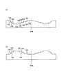
上述の位相構造は、回折構造、光路差付与構造の何れであってもよい。回折構造としては、図1に模式的に示すように、複数の輪帯100から構成され、光軸を含む断面形状が鋸歯形状であるものや、図2に模式的に示すように、段差101の方向が有効径内で同一である複数の輪帯102から構成され、光軸を含む断面形状が階段形状であるものや、図3に模式的に示すように、内部に階段構造が形成された複数の輪帯103から構成されるものや、図4に模式的に示すように、段差104の方向が有効径途中で入れ替わる複数の輪帯105から構成され、光軸を含む断面形状が階段形状であるものがある。また、光路差付与構造としては、図4に模式的に示すように、段差104の方向が有効径途中で入れ替わる複数の輪帯105から構成され、光軸を含む断面形状が階段形状であるものがある。従って、図4に模式的に示した構造は、回折構造である場合もあるし、光路差付与構造である場合もある。尚、図1乃至図4は、各位相構造を平面上に形成した場合を模式的に示したものであるが、各位相構造を球面或いは非球面上に形成してもよい。
尚、本明細書では、図1、2、及び4に示したような複数の輪帯から構成される回折構造を記号「DOE」で表し、図3に示したような内部に階段構造が形成された複数の輪帯から構成される回折構造を記号「HOE」で表すものとする。
The phase structure described above may be either a diffraction structure or an optical path difference providing structure. As schematically shown in FIG. 1, the diffractive structure includes a plurality of
In this specification, a diffraction structure composed of a plurality of annular zones as shown in FIGS. 1, 2, and 4 is represented by the symbol “DOE”, and a staircase structure is formed inside as shown in FIG. A diffractive structure composed of a plurality of annular zones is represented by the symbol “HOE”.
請求項1〜4に記載の発明のように、波長λ1の光束を緩い収束光として対物レンズに入射させ、波長λ3の光束を緩い発散光として対物レンズに入射させることにより、例えば、波長λ1の光束を平行光として入射させる場合と比較して、対物レンズの光学系倍率を抑えることができ、トラッキング時の収差の発生量を抑えることが可能となる。 As in the first to fourth aspects of the present invention, the light beam having the wavelength λ1 is incident on the objective lens as the loosely convergent light, and the light beam having the wavelength λ3 is incident on the objective lens as the loosely divergent light. Compared with the case where the light beam is incident as parallel light, the optical system magnification of the objective lens can be suppressed, and the amount of aberration generated during tracking can be suppressed.
また、保護基板厚t2が0.9×t1≦t2、光学系倍率m1が0<m1≦1/15、光学系倍率m3が−1/15≦m3<0の少なくとも1つが満たされていると、従来の対物レンズよりも薄いスーパースリムレンズであっても、トラッキング時の収差の発生量を押さえることができる。 Further, when at least one of the protective substrate thickness t2 is 0.9 × t1 ≦ t2, the optical system magnification m1 is 0 <m1 ≦ 1/15, and the optical system magnification m3 is −1 / 15 ≦ m3 <0 is satisfied. Even with a super slim lens that is thinner than a conventional objective lens, the amount of aberration generated during tracking can be suppressed.
請求項5記載の発明は、請求項1〜4のいずれか一項に記載の対物レンズにおいて、前記対物レンズの少なくとも1つの光学面に位相構造が設けられていることを特徴とする。 According to a fifth aspect of the present invention, in the objective lens according to any one of the first to fourth aspects, a phase structure is provided on at least one optical surface of the objective lens.
請求項5記載の発明によれば、対物レンズの少なくとも1つの光学面に位相構造が設けられているので、この位相構造によって第1光ディスクと第2光ディスクとの互換、対物レンズがプラスチックを材料としている場合には材料の屈折率の温度依存性により温度変化時に生じる収差補正、又は最も波長の短い第1光ディスクの色補正等を行うことができる。 According to the invention described in claim 5, since the phase structure is provided on at least one optical surface of the objective lens, the phase structure is compatible with the first optical disk and the second optical disk, and the objective lens is made of plastic. In this case, it is possible to correct aberrations that occur when the temperature changes due to temperature dependency of the refractive index of the material, or color correction of the first optical disk with the shortest wavelength.
請求項6記載の発明は、請求項5に記載の対物レンズにおいて、前記位相構造が回折構造であることを特徴とする。 According to a sixth aspect of the present invention, in the objective lens according to the fifth aspect, the phase structure is a diffractive structure.
請求項6記載の発明によれば、位相構造が回折構造であるので、第1光ディスクと第2光ディスクとの互換、対物レンズの温度に対する収差補正、又は第1光ディスクの色補正等をより効果的に行うことができる。 According to the sixth aspect of the present invention, since the phase structure is a diffractive structure, compatibility between the first optical disk and the second optical disk, aberration correction with respect to the temperature of the objective lens, or color correction of the first optical disk is more effective. Can be done.
請求項7記載の発明は、請求項6記載の対物レンズにおいて、
前記対物レンズのアッベ数νdは、
40≦νd≦90
を満たし、前記回折構造において前記第3光ディスクの記録又は再生には使用しない領域に形成された各輪帯間の光軸に平行な方向の段差量doutは、
(2k−1)×λ1/(n1−1)≦dout<2k×λ1/(n1−1)
を満たすことを特徴とする。
The invention according to claim 7 is the objective lens according to claim 6,
The Abbe number νd of the objective lens is
40 ≦ νd ≦ 90
The step amount d out in the direction parallel to the optical axis between the annular zones formed in the region not used for recording or reproduction of the third optical disc in the diffractive structure is
(2k−1) × λ1 / (n1-1) ≦ d out <2k × λ1 / (n1-1)
It is characterized by satisfying.
請求項7記載の発明によれば、対物レンズのアッベ数νdが、40≦νd≦90を満たし、回折構造において第3光ディスクの記録及び/又は再生には使用しない領域に形成された各輪帯間の光軸に平行な方向の段差量doutが、(2k−1)×λ1/(n1−1)≦dout<2k×λ1/(n1−1)を満たしているので、前記領域を通過した波長λ3の光束は2つ以上の不要回折光に光量が分散され、第3光ディスクのフォーカス信号に強い疑似信号が生じない。したがって、良好に対物レンズのフォーカシングを行うことができる。 According to the seventh aspect of the present invention, each annular zone formed in an area where the Abbe number νd of the objective lens satisfies 40 ≦ νd ≦ 90 and is not used for recording and / or reproduction of the third optical disk in the diffractive structure. The step amount d out in the direction parallel to the optical axis between the two satisfies (2k−1) × λ1 / (n1-1) ≦ d out <2k × λ1 / (n1-1). The light beam having the wavelength λ3 that has passed is dispersed in two or more unnecessary diffracted lights, and no strong pseudo signal is generated in the focus signal of the third optical disk. Therefore, the objective lens can be favorably focused.
請求項8記載の発明は、請求項7記載の対物レンズにおいて、
5×λ1/(n1−1)≦dout<6×λ1/(n1−1)
を満たすことを特徴とする。
The invention according to
5 × λ1 / (n1-1) ≦ d out <6 × λ1 / (n1-1)
It is characterized by satisfying.
請求項8記載の発明によれば、5×λ1/(n1−1)≦dout<6×λ1/(n1−1)が満たされているので、使用する波長λ1,λ2の光束における回折光は理論上の回折効率が高くなる。 According to the eighth aspect of the invention, since 5 × λ1 / (n1-1) ≦ d out <6 × λ1 / (n1-1) is satisfied, the diffracted light in the light beams having the wavelengths λ1 and λ2 to be used is satisfied. Increases the theoretical diffraction efficiency.
請求項9記載の発明は、請求項7又は8に記載の対物レンズにおいて、
前記第1光源から出射される光束の波長が+10nm変化した光束を入射させた際に、近軸集光位置をP0、前記波長λ3の光束の記録及び/又は再生に用いられる第1領域のうち、最も光軸より遠い領域を通過した光束の集光位置をP1、前記第1領域より外側に配置される第2領域のうち、最も光軸に近い領域を通過した光束の集光位置をP2、最も光軸より遠い領域を通過した光束の集光位置をP3とすると、
1.7×10⁻³≦|P2−P3|≦7.0×10⁻³
P0≦P2≦P1又はP1≦P2≦P0
を満たすことを特徴とする。
The invention according to claim 9 is the objective lens according to
Among the first regions used for recording and / or reproducing the light beam having the paraxial condensing position P0 and the light beam having the wavelength λ3 when a light beam whose wavelength of the light beam emitted from the first light source is changed by +10 nm is incident. , P1 is the condensing position of the light beam that has passed through the region farthest from the optical axis, and P2 is the condensing position of the light beam that has passed through the region closest to the optical axis among the second regions arranged outside the first region. If the light collection position of the light beam that has passed through the region farthest from the optical axis is P3,
1.7 × 10 −3 ≦ | P2-P3 | ≦ 7.0 × 10 −3
P0 ≦ P2 ≦ P1 or P1 ≦ P2 ≦ P0
It is characterized by satisfying.
さらに記録・再生信号に悪影響を与えないためには、低い光量ながらも不要回折光が波長λ3の光束の集光スポット位置に集光しないことが望ましい。最も光量の高い2つの回折次数光の集光位置と球面収差のうち、球面収差は第1光ディスクに対する第2光ディスクの光学系倍率から定められる。一方波長特性も第1光ディスクに対する第2光ディスクの光学系倍率より定められるため、球面収差と波長特性の両方の観点から適当な光学系倍率を設定する。
集光位置は対物レンズの色収差により決定される。フレアの集光位置をフォーカス位置より可能な限り離すためには、色収差の絶対値を大きくする必要がある。しかし色収差が大きくなると、回折ピッチが小さくなって効率が低下したり、モードホップ時に記録が不可能となる問題があるため、色収差とフレアの集光位置のバランスを取ることが重要となる。
これらのことから、請求項9記載の発明のように、近軸集光位置をP0、波長λ3の光束の記録及び/又は再生に用いられる第1領域のうち、最も光軸より遠い領域を通過した光束の集光位置をP1、第1領域より外側に配置される第2領域のうち、最も光軸に近い領域を通過した光束の集光位置をP2、最も光軸より遠い領域を通過した光束の集光位置をP3とすると、
1.7×10⁻³≦|P2−P3|≦7.0×10⁻³
P0≦P2≦P1又はP1≦P2≦P0
が満たされていれば、波長が短くNAが高いため誤差感度が厳しい波長λ1の光束に対して、波長変化時や温度変化時、又はモードホップ時にも波面収差劣化を押さえることができる。また開口数NA3以上の波長λ3の光束に対して光ディスク上において集光スポットと異なる位置に集光させながら光密度を薄くすることができる。
Further, in order not to adversely affect the recording / reproducing signal, it is desirable that unnecessary diffracted light should not be condensed at the condensing spot position of the light beam having the wavelength λ3 even though the light amount is low. Of the condensing position and spherical aberration of the two diffraction orders with the highest light quantity, the spherical aberration is determined from the optical system magnification of the second optical disc with respect to the first optical disc. On the other hand, since the wavelength characteristic is also determined by the optical system magnification of the second optical disk relative to the first optical disk, an appropriate optical system magnification is set from the viewpoint of both spherical aberration and wavelength characteristics.
The condensing position is determined by the chromatic aberration of the objective lens. In order to make the flare condensing position as far as possible from the focus position, it is necessary to increase the absolute value of the chromatic aberration. However, as chromatic aberration increases, there is a problem that the diffraction pitch decreases and efficiency decreases, and recording becomes impossible at the time of mode hopping. Therefore, it is important to balance chromatic aberration and condensing position of flare.
For these reasons, as in the ninth aspect of the invention, the paraxial condensing position is P0, and the first region used for recording and / or reproducing the light flux with wavelength λ3 passes through the region farthest from the optical axis. P1 is the condensing position of the luminous flux, and P2 is the condensing position of the luminous flux that has passed through the area closest to the optical axis among the second areas arranged outside the first area, and has passed through the area farthest from the optical axis. If the light collecting position is P3,
1.7 × 10 −3 ≦ | P2-P3 | ≦ 7.0 × 10 −3
P0 ≦ P2 ≦ P1 or P1 ≦ P2 ≦ P0
Is satisfied, the wavefront aberration deterioration can be suppressed even when the wavelength is changed, the temperature is changed, or the mode is hopped with respect to the light beam having the wavelength λ1, which has a short wavelength and a high NA, and the error sensitivity is severe. Further, it is possible to reduce the light density while condensing a light beam having a wavelength λ3 having a numerical aperture NA3 or more at a position different from the condensing spot on the optical disc.
請求項10記載の発明は、請求項7又は8に記載の対物レンズにおいて、
前記波長λ1の光束で波長が変化した場合に、縦球面収差における前記第1領域内での収差の傾きと、第2領域内での収差の傾きが同方向となっていることを特徴とする。
The invention according to
When the wavelength is changed by the light beam having the wavelength λ1, the inclination of the aberration in the first region and the inclination of the aberration in the second region in the longitudinal spherical aberration are in the same direction. .
請求項10記載の発明によれば、波長λ1の光束で波長が変化した場合に、縦球面収差における前記第1領域内での収差の傾きと、第2領域内での収差の傾きが同方向となっている。縦球面収差における第1領域内での収差の傾きと第2領域内での収差の傾きとが同方向とは、第1領域において光が通過する光軸からの距離が離れるにつれて光が対物レンズから離れて光軸と交わる場合、第2領域でも光が通過する光軸からの距離が離れるにつれて光が対物レンズから離れて光軸と交わることである。他方、第1領域において光が通過する光軸からの距離が離れるにつれて光が対物レンズから近づいて光軸と交わる場合、第2領域でも光が通過する光軸からの距離が離れるにつれて光が対物レンズに近づいて光軸と交わることでもある。ここで、高次収差は光学素子の組み合わせによって解消することは困難であるが、上述したように第1領域を通過した光束の集光位置の変位方向と、前記第2領域を通過した光束の集光位置の変位方向とが同方向であれば、波長変化時や温度変化時にも波面収差に高次収差を生じさせることなく第3光ディスク側において良好に開口制限を行うことができる。 According to the tenth aspect of the present invention, when the wavelength is changed by the light flux having the wavelength λ1, the inclination of the aberration in the first area and the inclination of the aberration in the second area in the longitudinal spherical aberration are in the same direction. It has become. In the longitudinal spherical aberration, the inclination of the aberration in the first region and the inclination of the aberration in the second region are in the same direction. As the distance from the optical axis through which light passes in the first region increases, the light becomes an objective lens. In the second region, the light is separated from the objective lens and intersects the optical axis as the distance from the optical axis through which the light passes is also increased in the second region. On the other hand, when light approaches the objective lens and crosses the optical axis as the distance from the optical axis through which light passes in the first region, the light becomes objective as the distance from the optical axis through which light passes also in the second region. It is also approaching the lens and crossing the optical axis. Here, although it is difficult to eliminate high-order aberrations by combining optical elements, as described above, the displacement direction of the condensing position of the light beam that has passed through the first region and the direction of the light beam that has passed through the second region. If the condensing position is displaced in the same direction, aperture restriction can be satisfactorily performed on the third optical disc side without causing higher-order aberrations in wavefront aberration even when the wavelength is changed or the temperature is changed.
請求項11記載の発明は、請求項6記載の対物レンズにおいて、
前記波長λ3の光束が入射した場合に、前記光学面において前記波長λ3の光束に対する開口数以上の領域を通過した光は、前記第3光ディスク上で集光スポット位置より0.01mm以上離れた位置に集光することを特徴とする。
The invention described in claim 11 is the objective lens described in claim 6,
When the light beam having the wavelength λ3 is incident, the light that has passed through the region on the optical surface having a numerical aperture equal to or larger than the numerical aperture for the light beam having the wavelength λ3 is located at a distance of 0.01 mm or more from the focused spot position on the third optical disk It is characterized by condensing light.
請求項11記載の発明によれば、波長λ3の光束が入射した場合に、光学面において波長λ3の光束に対する開口数以上の領域を通過した光は、第3光ディスク上で集光スポット位置より0.01mm以上離れた位置に集光しているので、開口数NA3以上の波長λ3の光束に対して、光ディスク上において波長λ3の記録・再生に問題ない程度に集光スポットから離れた位置に集光させることができ、さらには誤差感度が大きい波長λ1の光束の波長変化、温度変化、モードホップ時の波面収差劣化を抑えることができる。 According to the eleventh aspect of the present invention, when a light beam having a wavelength of λ3 is incident, light that has passed through an area on the optical surface equal to or larger than the numerical aperture for the light beam having a wavelength of λ3 is 0 Since the light is condensed at a position distant by .01 mm or more, the light beam with the wavelength λ3 having a numerical aperture NA3 or more is collected at a position away from the condensing spot on the optical disk to the extent that there is no problem in recording / reproducing of the wavelength λ3. In addition, it is possible to suppress the wavelength change, temperature change, and wavefront aberration deterioration at the time of mode hopping of the light beam having the wavelength λ1 with high error sensitivity.
請求項12記載の発明は、請求項6に記載の対物レンズにおいて、前記位相構造は、前記波長λ1、λ2及びλ3の光束のうち少なくとも1つの光束に対して正の回折作用を与えることを特徴とする。 According to a twelfth aspect of the present invention, in the objective lens according to the sixth aspect, the phase structure gives a positive diffractive action to at least one of the light beams having the wavelengths λ1, λ2, and λ3. And
請求項12記載の発明によれば、位相構造が、波長λ1、λ2及びλ3の光束のうち少なくとも1つの光束に対して正の回折作用を与えるので、例えば対物レンズがプラスチックを材料としている場合、材料の屈折率の温度依存性により対物レンズの温度に対する収差特性補正が可能となる。 According to the invention of claim 12, since the phase structure gives a positive diffractive action to at least one of the light beams of wavelengths λ1, λ2, and λ3, for example, when the objective lens is made of plastic, Due to the temperature dependence of the refractive index of the material, it is possible to correct aberration characteristics with respect to the temperature of the objective lens.
請求項13記載の発明は、請求項10記載の対物レンズにおいて、
前記第1、第2及び第3光ディスクのうち少なくとも1つの光ディスクに対して、その情報記録面上に形成される集光スポットの波面収差の成分である、温度が上昇した場合の3次の球面収差変化は、正であることを特徴としている。
The invention according to claim 13 is the objective lens according to
A third-order spherical surface when temperature rises, which is a wavefront aberration component of a focused spot formed on the information recording surface of at least one of the first, second, and third optical discs The aberration change is characterized by being positive.
ここで、長波長変化に対する3次の球面収差変化と、温度上昇に対する3次の球面収差変化との符号が逆方向であれば、通常高温環境ではレーザの発振波長が長くなるため両者が打ち消しあう。さらに完全に打ち消すのではなく、請求項13のように球面収差変化として正の球面収差を残留させれば、波長変化時も温度変化時も波面収差劣化を抑えることができる。 Here, if the signs of the third-order spherical aberration change with respect to the long wavelength change and the third-order spherical aberration change with respect to the temperature rise are in opposite directions, the laser oscillation wavelength becomes longer in a normal high temperature environment, so both cancel each other. . Furthermore, if the positive spherical aberration remains as the spherical aberration change as in the thirteenth aspect, instead of canceling out completely, the wavefront aberration deterioration can be suppressed at both the wavelength change and the temperature change.
請求項14記載の発明は、請求項6に記載の対物レンズにおいて、前記位相構造のパワーが負であることを特徴とする。 The invention according to claim 14 is the objective lens according to claim 6, wherein the power of the phase structure is negative.
請求項14に記載の発明のように、対物レンズの光学面に設ける位相構造を、波長λ1、λ2及びλ3の光束のうち少なくとも1つの光束に対して負の回折パワーと対物レンズの材料により正の屈折パワーとで打ち消すことで、波長変動による色収差を補正できる。 As in the invention described in claim 14, the phase structure provided on the optical surface of the objective lens is made positive by at least one of the light beams having wavelengths λ1, λ2, and λ3 depending on the negative diffraction power and the material of the objective lens. The chromatic aberration due to the wavelength variation can be corrected by canceling with the refractive power of.
請求項15記載の発明は、請求項5〜14のいずれか一項に記載の対物レンズにおいて、前記位相構造が、前記光学面の前記波長λ2の光束が通過する領域に設けられていることを特徴とする。 According to a fifteenth aspect of the invention, in the objective lens according to any one of the fifth to fourteenth aspects, the phase structure is provided in a region through which the light flux having the wavelength λ2 passes. Features.
請求項15記載の発明によれば、光学面の波長λ2の光束が通過する領域に位相構造が設けられているので、第1光ディスクと第2光ディスクとを互換することが可能となる。また、例えば第1光ディスクと第2光ディスクとの有効径がほぼおなじHDとDVDとの場合には、第1光ディスクの色補正も可能となる。 According to the fifteenth aspect of the invention, since the phase structure is provided in the region where the light flux having the wavelength λ2 of the optical surface passes, the first optical disc and the second optical disc can be made compatible. Further, for example, when the effective diameters of the first optical disc and the second optical disc are substantially the same as HD and DVD, color correction of the first optical disc is possible.
請求項16記載の発明は、請求項6〜15のいずれか一項に記載の対物レンズにおいて、前記位相構造において、前記波長λ1の光束は実質的に位相差を与えられずに透過し、前記波長λ2の光束は実質的に位相差を与えられて回折することを特徴とする。 According to a sixteenth aspect of the present invention, in the objective lens according to any one of the sixth to fifteenth aspects, in the phase structure, the light flux having the wavelength λ1 transmits substantially without being given a phase difference, and The light beam having the wavelength λ2 is substantially diffracted by being given a phase difference.
請求項16記載の発明によれば、位相構造によって、波長λ1の光束は実質的に位相差を与えられずに透過し、波長λ2の光束は実質的に位相差を与えられて回折するので、波長に対して選択的に回折作用を付与することができる。 According to the sixteenth aspect of the present invention, the light beam having the wavelength λ1 is transmitted without being substantially given a phase difference, and the light beam having the wavelength λ2 is substantially diffracted with a phase difference. A diffraction effect can be selectively imparted to the wavelength.
請求項17記載の発明は、請求項6〜15のいずれか一項に記載の対物レンズにおいて、前記位相構造において、前記波長λ2の光束は実質的に位相差を与えられずに透過し、前記波長λ1の光束は実質的に位相差を与えられて回折することを特徴とする。 According to a seventeenth aspect of the present invention, in the objective lens according to any one of the sixth to fifteenth aspects, in the phase structure, the light flux having the wavelength λ2 is transmitted without being substantially given a phase difference, and The light beam having the wavelength λ1 is substantially diffracted by being given a phase difference.
請求項18記載の発明は、請求項14に記載の対物レンズにおいて、前記第1光ディスクの情報記録面上に形成される集光スポットにおける前記波長λ1の光束の波長変化に対する光軸方向の波面収差最小位置変化量dfb/dλが、
|dfb/dλ|≦0.1[μm/nm]
を満たすことを特徴とする。
According to an eighteenth aspect of the present invention, in the objective lens according to the fourteenth aspect, the wavefront aberration in the optical axis direction with respect to the wavelength change of the light flux having the wavelength λ1 at the focused spot formed on the information recording surface of the first optical disc. The minimum position change amount dfb / dλ is
| Dfb / dλ | ≦ 0.1 [μm / nm]
It is characterized by satisfying.
請求項19記載の発明は、請求項14に記載の対物レンズにおいて、前記第2光ディスクの情報記録面上に形成される集光スポットにおける前記波長λ2の光束の波長変化に対する光軸方向の波面収差最小位置変化量dfb/dλが、
|dfb/dλ|≦0.2[μm/nm]
を満たすことを特徴とする。
According to a nineteenth aspect of the present invention, there is provided the objective lens according to the fourteenth aspect, wherein the wavefront aberration in the optical axis direction with respect to the wavelength change of the light flux having the wavelength λ2 at the focused spot formed on the information recording surface of the second optical disc The minimum position change amount dfb / dλ is
| Dfb / dλ | ≦ 0.2 [μm / nm]
It is characterized by satisfying.
請求項20記載の発明は、請求項5〜19のいずれか一項に記載の対物レンズにおいて、前記位相構造は、光軸を中心とした同心円状の複数の輪帯で構成される回折構造であり、前記位相構造の光軸を含む断面形状が鋸歯形状であり、波長λ3の記録及び/又は再生に使用される領域に形成された前記各輪帯の光軸方向の段差の距離dが、
8×λ1/(n1−1)≦d<9×λ1/(n1−1)
を満たすことを特徴とする。
n1:前記波長λ1の光束に対する前記対物レンズの屈折率
The invention according to claim 20 is the objective lens according to any one of claims 5 to 19, wherein the phase structure is a diffractive structure composed of a plurality of concentric annular zones around the optical axis. The cross-sectional shape including the optical axis of the phase structure is a sawtooth shape, and the distance d of the step in the optical axis direction of each annular zone formed in the region used for recording and / or reproduction of the wavelength λ3,
8 × λ1 / (n1-1) ≦ d <9 × λ1 / (n1-1)
It is characterized by satisfying.
n1: Refractive index of the objective lens with respect to the light beam having the wavelength λ1
請求項21記載の発明は、請求項5〜19のいずれか一項に記載の対物レンズにおいて、前記位相構造は、光軸を中心とした同心円状の複数の輪帯で構成される回折構造であり、前記位相構造の光軸を含む断面形状が鋸歯形状であり、波長λ3の記録及び/又は再生に使用される領域に形成された前記各輪帯の光軸方向の段差の距離dが、
6×λ1/(n1−1)≦d<7×λ1/(n1−1)
を満たすことを特徴とする。
n1:前記波長λ1の光束に対する前記対物レンズの屈折率
According to a twenty-first aspect of the present invention, in the objective lens according to any one of the fifth to nineteenth aspects, the phase structure is a diffractive structure composed of a plurality of concentric annular zones around the optical axis. The cross-sectional shape including the optical axis of the phase structure is a sawtooth shape, and the distance d of the step in the optical axis direction of each annular zone formed in the region used for recording and / or reproduction of the wavelength λ3,
6 × λ1 / (n1-1) ≦ d <7 × λ1 / (n1-1)
It is characterized by satisfying.
n1: Refractive index of the objective lens with respect to the light beam having the wavelength λ1
請求項22記載の発明は、請求項5〜19のいずれか一項に記載の対物レンズにおいて、前記位相構造は、光軸を中心とした同心円状の複数の輪帯で構成される回折構造であり、前記位相構造の光軸を含む断面形状が鋸歯形状であり、波長λ3の記録及び/又は再生に使用される領域に形成された前記各輪帯の光軸方向の段差の距離dが、
10×λ1/(n1−1)≦d<12×λ1/(n1−1)を満たすことを特徴とする。
n1:前記波長λ1の光束に対する前記対物レンズの屈折率
According to a twenty-second aspect of the present invention, in the objective lens according to any one of the fifth to nineteenth aspects, the phase structure is a diffractive structure composed of a plurality of concentric annular zones around the optical axis. The cross-sectional shape including the optical axis of the phase structure is a sawtooth shape, and the distance d of the step in the optical axis direction of each annular zone formed in the region used for recording and / or reproduction of the wavelength λ3,
10 × λ1 / (n1-1) ≦ d <12 × λ1 / (n1-1) is satisfied.
n1: Refractive index of the objective lens with respect to the light beam having the wavelength λ1
請求項23記載の発明は、請求項1〜22のいずれか一項に記載の対物レンズにおいて、前記波長λ1の光束に対する前記対物レンズの焦点距離f1が、0.8mm≦f1≦4.0mmを満たすことを特徴とする。 According to a twenty-third aspect of the present invention, in the objective lens according to any one of the first to twenty-second aspects, a focal length f1 of the objective lens with respect to the light flux having the wavelength λ1 is 0.8 mm ≦ f1 ≦ 4.0 mm. It is characterized by satisfying.
請求項24記載の発明は、請求項23記載の対物レンズにおいて、
前記波長λ1の光束に対する前記対物レンズの焦点距離f1が、
1.3mm≦f1≦2.2mmを満たすことを特徴とする。
The invention according to claim 24 is the objective lens according to claim 23,
The focal length f1 of the objective lens with respect to the light beam having the wavelength λ1 is
It is characterized by satisfying 1.3 mm ≦ f1 ≦ 2.2 mm.
請求項25記載の発明は、請求項1〜24のいずれか一項に記載の対物レンズにおいて、前記波長λ3の光束に対する前記対物レンズの前記光ディスク側の開口数NA3が、0.49≦NA3≦0.54を満たすことを特徴とする。 According to a twenty-fifth aspect of the present invention, in the objective lens according to any one of the first to twenty-fourth aspects, a numerical aperture NA3 on the optical disc side of the objective lens with respect to a light beam having the wavelength λ3 is 0.49 ≦ NA3 ≦. It is characterized by satisfying 0.54.
請求項26記載の発明は、請求項1〜25のいずれか一項に記載の対物レンズにおいて、t1=t2であることを特徴とする。
The invention according to claim 26 is the objective lens according to any one of
請求項27記載の発明は、請求項1〜26のいずれか一項に記載の対物レンズにおいて、前記波長λ2の光束に対する前記対物レンズの光学系倍率m2は、m2=0であることを特徴とする。
The invention according to claim 27 is the objective lens according to any one of
請求項27記載の発明によれば、波長λ2の光束に対する対物レンズの光学系倍率m2がm2=0であるので、NAの高い第2光ディスクに対して対物レンズに平行光が入射するため、トラッキング時にコマ収差が生じない。 According to the twenty-seventh aspect of the invention, since the optical system magnification m2 of the objective lens with respect to the light beam having the wavelength λ2 is m2 = 0, the parallel light is incident on the objective lens with respect to the second optical disk having a high NA. Sometimes coma does not occur.
請求項28記載の発明は、請求項1〜27のいずれか一項に記載の対物レンズにおいて、プラスチック製であることを特徴とする。 A twenty-eighth aspect of the invention is the objective lens according to any one of the first to twenty-seventh aspects, wherein the objective lens is made of plastic.
請求項29記載の発明は、請求項1〜27のいずれか一項に記載の対物レンズにおいて、ガラス製であることを特徴とする。 A twenty-ninth aspect of the present invention is the objective lens according to any one of the first to twenty-seventh aspects, wherein the objective lens is made of glass.
請求項30記載の発明は、請求項1〜29のいずれか一項に記載の対物レンズにおいて、2つのレンズを組み合わせて構成されることを特徴とする。 A thirty-third aspect of the invention is characterized in that in the objective lens according to any one of the first to twenty-ninth aspects, two lenses are combined.
請求項31記載の発明は、請求項5に記載の対物レンズにおいて、前記対物レンズは2つ以上のレンズで構成され、最も前記光源側に配置されるレンズに前記位相構造が設けられていることを特徴とする。 According to a thirty-first aspect of the present invention, in the objective lens according to the fifth aspect, the objective lens is composed of two or more lenses, and the lens disposed closest to the light source is provided with the phase structure. It is characterized by.
請求項32記載の発明は、請求項1〜31のいずれか一項に記載の対物レンズを備えることを特徴とする。 A thirty-second aspect of the invention includes the objective lens according to any one of the first to thirty-first aspects.
請求項33記載の発明は、請求項32記載の光ピックアップ装置において、
前記波長λ3の光束の光路上に開口制限素子が配置されることを特徴とする。
The invention according to claim 33 is the optical pickup device according to claim 32, wherein
An aperture limiting element is disposed on the optical path of the light beam having the wavelength λ3.
請求項34記載の発明は、請求項32記載の光ピックアップ装置において、
前記開口制限素子が、液晶素子又は波長選択フィルタであることを特徴とする。
The invention according to claim 34 is the optical pickup device according to claim 32,
The aperture limiting element is a liquid crystal element or a wavelength selection filter.
請求項35記載の発明は、請求項32記載の光ピックアップ装置において、
前記波長λ1の光束の光路上に、前記波長λ1の光束の色収差を補正する機能を有する色収差補正素子が配置されていることを特徴とする。
The invention according to claim 35 is the optical pickup device according to claim 32,
A chromatic aberration correction element having a function of correcting chromatic aberration of the light beam having the wavelength λ1 is disposed on the optical path of the light beam having the wavelength λ1.
請求項36記載の発明は、請求項32に記載の光ピックアップ装置において、前記第1光ディスクに対して情報の再生又は記録を行う際には、前記第1光ディスクの情報記録面上で反射された前記第1光源からの光束を受光し、前記第2光ディスクに対して情報の再生又は記録を行う際には、前記第2光ディスクの情報記録面上で反射された前記第2光源からの光束を受光するとともに、前記第3光ディスクに対して情報の再生又は記録を行う際には、前記第3光ディスクの情報記録面上で反射された前記第3光源からの光束を受光する光検出器を備えることを特徴とする。 The invention according to claim 36 is the optical pickup device according to claim 32, wherein when information is reproduced or recorded on the first optical disc, it is reflected on the information recording surface of the first optical disc. When the light beam from the first light source is received and information is reproduced or recorded on the second optical disk, the light beam from the second light source reflected on the information recording surface of the second optical disk is used. And a light detector for receiving a light beam from the third light source reflected on the information recording surface of the third optical disk when receiving or recording information on the third optical disk. It is characterized by that.
請求項37記載の発明は、請求項36に記載の光ピックアップ装置において、前記波長λ1、λ2及びλ3の各光束の共通光路上に、光軸方向に移動可能なカップリングレンズが配置されることを特徴とする。 According to a thirty-seventh aspect of the present invention, in the optical pickup device according to the thirty-sixth aspect, a coupling lens movable in the optical axis direction is disposed on a common optical path of the light beams having the wavelengths λ1, λ2, and λ3. It is characterized by.
ここで、対物レンズの倍率は3つの波長に対して全て異なるが、請求項37記載の発明のように、カップリングレンズを波長λ1、λ2及びλ3の各光束の共通光路上に配置させて、カップリングレンズを移動させて3つの波長に対して対物レンズとカップリングレンズとを組み合わせた光学系の共役長を揃えていれば、3つの波長に対してセンサを共通化したり複数の光源を1パッケージ化したレーザを使用することができる。カップリングレンズは単レンズ、複数レンズのいずれでも良く、複数レンズの場合そのうち1枚だけが移動する場合もあれば複数が同時に移動する場合も想定される。 Here, the magnifications of the objective lens are all different with respect to the three wavelengths, but as in the invention of claim 37, the coupling lens is arranged on the common optical path of the light beams of wavelengths λ1, λ2, and λ3, If the conjugate length of the optical system in which the objective lens and the coupling lens are combined with respect to the three wavelengths by moving the coupling lens is made uniform, a sensor can be used for the three wavelengths or a plurality of light sources can be used. Packaged lasers can be used. The coupling lens may be either a single lens or a plurality of lenses. In the case of a plurality of lenses, only one of them may move or a plurality of lenses may move simultaneously.
請求項38記載の発明は、請求項37に記載の光ピックアップ装置において、前記波長λ1、λ2及びλ3の各光束の共通光路上に、カップリングレンズと液晶素子とが配置されることを特徴とする。 A thirty-eighth aspect of the invention is the optical pickup device according to the thirty-seventh aspect, wherein a coupling lens and a liquid crystal element are disposed on a common optical path of the light beams having the wavelengths λ1, λ2, and λ3. To do.
対物レンズの倍率は3つの波長に対して全て異なるが、請求項38記載の発明のように、カップリングレンズと液晶素子とが波長λ1、λ2及びλ3の各光束の共通光路上に配置させて、3つの波長に対して対物レンズ、カップリングレンズ及び液晶素子を組み合わせた光学系の共役長を揃えることで、3つの波長に対してセンサを共通化したり複数の光源を1パッケージ化したレーザを使用することができる。 Although the magnification of the objective lens is different for all three wavelengths, the coupling lens and the liquid crystal element are arranged on the common optical path of the light beams having the wavelengths λ1, λ2, and λ3 as in the invention of claim 38. By aligning the conjugate length of an optical system that combines an objective lens, coupling lens, and liquid crystal element for three wavelengths, a laser with a common sensor for three wavelengths or a package of multiple light sources Can be used.
請求項39記載の発明は、請求項37又は38記載の光ピックアップ装置において、前記カップリングレンズの少なくとも1面には、回折構造が形成されていることを特徴とする。 A thirty-ninth aspect of the present invention is the optical pickup device according to the thirty-seventh or thirty-eighth aspect, wherein a diffractive structure is formed on at least one surface of the coupling lens.
請求項39記載の発明によれば、カップリングレンズの少なくとも1面に回折構造が形成されているので、回折作用を用いて波長λ1の光束に対する色収差や温度変化時に生じる波面収差劣化を抑えることができる。 According to the 39th aspect of the invention, since the diffractive structure is formed on at least one surface of the coupling lens, the chromatic aberration with respect to the light flux having the wavelength λ1 and the wavefront aberration deterioration caused by the temperature change can be suppressed by using the diffraction action. it can.
請求項40記載の発明は、請求項39記載の光ピックアップ装置において、前記カップリングレンズの回折構造は、前記第1光ディスクの情報記録面上に形成される集光スポットにおける前記波長λ1の光束の波長変化に対する光軸方向の波面収差最小位置変化量dfb/dλが、
|dfb/dλ|≦0.1[μm/nm]
を満たすことを特徴とする。
The invention according to claim 40 is the optical pickup device according to claim 39, wherein the diffractive structure of the coupling lens is a beam of the wavelength λ1 at a focused spot formed on the information recording surface of the first optical disc. Wavefront aberration minimum position change amount dfb / dλ in the optical axis direction with respect to wavelength change is
| Dfb / dλ | ≦ 0.1 [μm / nm]
It is characterized by satisfying.
請求項41記載の発明は、請求項37に記載の光ピックアップ装置において、前記カップリングレンズと液晶素子とが一体化されていることを特徴とする。 The invention according to claim 41 is the optical pickup apparatus according to claim 37, wherein the coupling lens and the liquid crystal element are integrated.
請求項42記載の発明は、請求項36〜41のいずれか一項に記載の光ピックアップ装置において、前記第2光源と前記第3光源とが、同一の筐体内に格納されることで1パッケージ化されていることを特徴とする。 The invention according to claim 42 is the optical pickup device according to any one of claims 36 to 41, wherein the second light source and the third light source are housed in the same casing, so that one package is provided. It is characterized by that.
請求項43記載の発明は、請求項31に記載の光ピックアップ装置において、第1、第2及び第3光ディスクのうち少なくとも1つの情報記録面上で反射した光束を受光する光検出器に関して、前記第1光ディスクの情報記録面上で反射された前記第1光源からの光束及び前記第2光ディスクの情報記録面上で反射された前記第2光源からの光束を受光する光検出器と、前記第3光ディスクの情報記録面上で反射された前記第3光源からの光束を受光する光検出器とを備えることを特徴とする。 The invention according to claim 43 relates to the photodetector for receiving the light beam reflected on at least one information recording surface of the first, second and third optical disks in the optical pickup device according to claim 31. A photodetector for receiving the light beam from the first light source reflected on the information recording surface of the first optical disc and the light beam from the second light source reflected on the information recording surface of the second optical disc; And a photodetector for receiving the light beam from the third light source reflected on the information recording surface of the three optical discs.
請求項44記載の発明は、請求項43に記載の光ピックアップ装置において、前記波長λ1、λ2及びλ3の各光束の共通光路上にカップリングレンズが配置され、当該カップリングレンズの少なくとも1つの光学面に回折構造が設けられていることを特徴とする。 According to a 44th aspect of the present invention, in the optical pickup device according to the 43rd aspect, a coupling lens is disposed on a common optical path of the light beams having the wavelengths λ1, λ2, and λ3, and at least one optical of the coupling lens is provided. A diffractive structure is provided on the surface.
請求項44記載の発明によれば、波長λ1、λ2及びλ3の各光束の共通光路上にカップリングレンズが配置され、当該カップリングレンズの少なくとも1つの光学面に回折構造が設けられているので、この回折構造により波長λ1,λ2の光束に対するセンサを共通化することができる。また、回折構造は同時に波長λ1の色収差補正を行うことも可能である。回折構造は1面又は複数の面に形成されていてもよい。波長λ3の光もカップリングレンズを通過するように構成すれば光学系全体の部品数の削減につながる。 According to the invention of claim 44, the coupling lens is disposed on the common optical path of the light beams having the wavelengths λ1, λ2, and λ3, and the diffractive structure is provided on at least one optical surface of the coupling lens. This diffractive structure makes it possible to share a sensor for light beams having wavelengths λ1 and λ2. In addition, the diffractive structure can simultaneously correct chromatic aberration of wavelength λ1. The diffractive structure may be formed on one surface or a plurality of surfaces. If the light of wavelength λ3 is configured to pass through the coupling lens, the number of parts of the entire optical system can be reduced.
請求項45記載の発明は、請求項44に記載の光ピックアップ装置において、
前記波長λ1の光束に対する前記カップリングレンズの焦点距離fcが、
6mm≦fc≦15mmを満たすことを特徴とする。
According to a 45th aspect of the present invention, in the optical pickup device of the 44th aspect,
The focal length fc of the coupling lens with respect to the light beam having the wavelength λ1 is
It is characterized by satisfying 6 mm ≦ fc ≦ 15 mm.
請求項46記載の発明は、請求項44記載の光ピックアップ装置において、
前記波長λ1の光束のみが通過する光路中に前記波長λ1の光束に対する色収差補正素子が配置されていることを特徴とする。
The invention according to claim 46 is the optical pickup device according to claim 44,
A chromatic aberration correction element for the light beam having the wavelength λ1 is disposed in an optical path through which only the light beam having the wavelength λ1 passes.
請求項47記載の発明は、請求項44〜46の何れか一項に記載の光ピックアップ装置において、前記第1光ディスクの情報記録面上で反射された前記第1光源からの光束及び前記第2光ディスクの情報記録面上で反射された前記第2光源からの光束を受光する光検出器と前記カップリングレンズとの間の光路中に非点収差板が配置されており、
少なくとも前記波長λ1及び波長λ2の光束のうち、一方の波長の光束が、前記非点収差板を反射してから前記カップリングレンズに入射することを特徴とする。
A 47th aspect of the present invention is the optical pickup device according to any one of the 44th to 46th aspects, wherein the light beam from the first light source reflected on the information recording surface of the first optical disc and the second light beam are reflected. An astigmatism plate is disposed in the optical path between the photodetector that receives the light beam from the second light source reflected on the information recording surface of the optical disc and the coupling lens;
At least one of the light beams having the wavelength λ1 and the wavelength λ2 is incident on the coupling lens after being reflected by the astigmatism plate.
請求項47記載の発明によれば、少なくとも波長λ1及び波長λ2の光束のうち、一方の波長の光束が、非点収差板を反射してからカップリングレンズに入射するようになっているが、この非点収差板は光検出器に入射する光に非点収差を与えるだけでなく光源からカップリングレンズに至る光を折り曲げる作用を有しているので、これらの作用を個別に有する部品を設置する必要がなくなり、結果的に光ピックアップ装置全体の部品点数を削減することができる。 According to the invention of claim 47, at least one of the light beams having the wavelength λ1 and the wavelength λ2 is incident on the coupling lens after reflecting the astigmatism plate. This astigmatism plate not only gives astigmatism to the light incident on the photodetector, but also has the effect of bending the light from the light source to the coupling lens. As a result, the number of parts of the entire optical pickup device can be reduced.
請求項48記載の発明は、請求項44〜46の何れか一項に記載の光ピックアップ装置において、
前記第1光ディスクの情報記録面上で反射された前記第1光源からの光束及び前記第2光ディスクの情報記録面上で反射された前記第2光源からの光束を受光する光検出器と前記カップリングレンズとの間の光路中に複合ビームスプリッタが配置されており、
前記波長λ1及び波長λ2の光束は、前記複合ビームスプリッタで光路合成されてから前記カップリングレンズに入射し、当該複合ビームスプリッタによって前記波長λ1及び波長λ2の光束の往路と復路との光路が異なることを特徴とする。
The invention according to claim 48 is the optical pickup device according to any one of claims 44 to 46, wherein:
The photodetector and the cup for receiving the light beam from the first light source reflected on the information recording surface of the first optical disc and the light beam from the second light source reflected on the information recording surface of the second optical disc. A composite beam splitter is placed in the optical path between the ring lens and
The light beams having the wavelengths λ1 and λ2 are combined in the optical path by the composite beam splitter and then incident on the coupling lens, and the optical paths of the forward and return paths of the light beams having the wavelengths λ1 and λ2 are different depending on the composite beam splitter. It is characterized by that.
請求項48記載の発明によれば、波長λ1及び波長λ2の光束の光路合成と往路及び復路を分岐する機能とを有する多機能な複合ビームスプリッタが用いられているので、光ピックアップ装置全体の部品点数を削減できる。 According to the invention of claim 48, since the multifunctional composite beam splitter having the function of combining the optical paths of the light beams having the wavelengths λ1 and λ2 and the function of branching the forward path and the return path is used, the components of the entire optical pickup device The score can be reduced.
請求項49記載の発明は、請求項48に記載の光ピックアップ装置において、
前記複合ビームスプリッタは、
波長に応じて光を透過又は反射するダイクロ機能を有する第1面と、
偏光方向に応じて透過又は反射するビームスプリッタ機能を有する第2面と、
光を反射する第3面とを備えることを特徴とする。
The invention according to claim 49 is the optical pickup device according to claim 48,
The composite beam splitter is
A first surface having a dichroic function of transmitting or reflecting light according to a wavelength;
A second surface having a beam splitter function of transmitting or reflecting according to the polarization direction;
And a third surface that reflects light.
請求項49記載の発明によれば、複合ビームスプリッタが、光路合成を行う第1面、往路と復路とを分岐する第2面以外に、光を反射する第3面を有するので、複合ビームスプリッタへの入射光に対する出射光の角度を自由に設定することが可能となる、光ピックアップ装置をコンパクトにすることができる。 According to the 49th aspect of the invention, the composite beam splitter has the third surface that reflects light in addition to the first surface that performs optical path synthesis and the second surface that branches the forward path and the return path. The optical pickup device that can freely set the angle of the outgoing light with respect to the incident light on can be made compact.
請求項50記載の発明は、請求項49記載の光ピックアップ装置において、
前記波長λ2の光束は、
前記第2光源から出射された場合には前記第1面及び前記第2面を透過した後に前記複合ビームスプリッタから出射され、前記カップリングレンズから出射された場合には前記第2面及び前記第3面で反射されることで前記複合ビームスプリッタから出射され、
前記波長λ1の光束は、
前記第1光源から出射された場合には前記第1面で反射された後に第2面を透過することで前記複合ビームスプリッタから出射され、前記カップリングレンズから出射された場合には前記第2面及び前記第3面で反射されることで前記複合ビームスプリッタから出射されることを特徴とする。
The invention according to claim 50 is the optical pickup device according to claim 49, wherein
The luminous flux of wavelength λ2 is
When it is emitted from the second light source, it is emitted from the composite beam splitter after passing through the first surface and the second surface, and when it is emitted from the coupling lens, the second surface and the second surface. It is emitted from the composite beam splitter by being reflected by three surfaces,
The luminous flux of wavelength λ1 is
When the light is emitted from the first light source, it is reflected by the first surface and then transmitted through the second surface to be emitted from the composite beam splitter, and when it is emitted from the coupling lens, the second light source. It is emitted from the composite beam splitter by being reflected by a surface and the third surface.
請求項51記載の発明は、請求項44に記載の光ピックアップ装置において、前記カップリングレンズに形成された前記回折構造は、光軸を中心とした同心円状の複数の輪帯で構成され、前記回折構造の光軸を含む断面形状が鋸歯形状であり、前記各輪帯の光軸方向の段差の距離dが、
2×λ1/(n1−1)≦d<3×λ1/(n1−1)
を満たすことを特徴とする。
n1:前記波長λ1の光束に対する前記カップリングレンズの屈折率
The invention according to claim 51 is the optical pickup device according to claim 44, wherein the diffractive structure formed on the coupling lens is composed of a plurality of concentric annular zones around an optical axis, The cross-sectional shape including the optical axis of the diffractive structure is a sawtooth shape, and the distance d of the step in the optical axis direction of each annular zone is
2 × λ1 / (n1-1) ≦ d <3 × λ1 / (n1-1)
It is characterized by satisfying.
n1: Refractive index of the coupling lens with respect to the light beam having the wavelength λ1
請求項52記載の発明は、請求項44〜51のいずれか一項に記載の光ピックアップ装置において、前記カップリングレンズの回折構造が、前記カップリングレンズの光ディスク側の光学面と前記光源側の光学面の両方に形成されていることを特徴とする。 The invention according to Claim 52 is the optical pickup device according to any one of Claims 44 to 51, wherein the diffractive structure of the coupling lens includes an optical surface on the optical disc side of the coupling lens and an optical surface on the light source side. It is formed on both optical surfaces.
請求項53記載の発明は、請求項52に記載の光ピックアップ装置において、前記カップリングレンズの前記光源側の光学面に形成される前記回折構造は、光軸を中心とした同心円状の複数の輪帯で構成され、前記回折構造の光軸を含む断面形状が鋸歯形状であり、前記各輪帯の光軸方向の段差の距離dが、
10×λ1/(n1−1)≦d<12×λ1/(n1−1)
を満たすことを特徴とする。
n1:前記波長λ1の光束に対する前記カップリングレンズの屈折率
The invention according to claim 53 is the optical pickup device according to claim 52, wherein the diffractive structure formed on the optical surface of the coupling lens on the light source side is a plurality of concentric circles centered on the optical axis. The cross-sectional shape including the optical axis of the diffractive structure is a sawtooth shape, and the distance d of the step in the optical axis direction of each annular zone is
10 × λ1 / (n1-1) ≦ d <12 × λ1 / (n1-1)
It is characterized by satisfying.
n1: Refractive index of the coupling lens with respect to the light beam having the wavelength λ1
請求項54記載の発明は、請求項52又は53に記載の光ピックアップ装置において、前記カップリングレンズの前記光源側の光学面に形成される前記回折構造において、前記波長λ1の光束は実質的に位相差を与えられずに透過し、前記波長λ2の光束は実質的に位相差を与えられて回折することを特徴とする。 According to a 54th aspect of the present invention, in the optical pickup device according to the 52nd or 53rd aspect, in the diffraction structure formed on the optical surface of the coupling lens on the light source side, the light flux having the wavelength λ1 is substantially The light beam is transmitted without being given a phase difference, and the light beam having the wavelength λ2 is substantially diffracted by being given a phase difference.
請求項55記載の発明は、請求項44に記載の光ピックアップ装置において、前記波長λ1及び波長λ2の光束が通過するカップリングレンズと、前記波長λ3の光束が通過するカップリングレンズとに別体化されて配置されていることを特徴とする。 According to a 55th aspect of the present invention, in the optical pickup device according to the 44th aspect, the coupling lens through which the light beams having the wavelengths λ1 and λ2 pass and the coupling lens through which the light beam having the wavelength λ3 pass are separately provided. It is characterized by being arranged.
請求項56記載の発明は、請求項43に記載の光ピックアップ装置において、前記第3光ディスクの情報記録面上で反射された前記第3光源からの光束を受光する光検出器がホログラムレーザであることを特徴とする。 According to a fifty-sixth aspect of the present invention, in the optical pickup device according to the forty-third aspect, the photodetector for receiving the light beam from the third light source reflected on the information recording surface of the third optical disc is a hologram laser. It is characterized by that.
請求項57記載の発明は、請求項32に記載の光ピックアップ装置において、前記第1、第2及び第3光ディスクのうち少なくとも1つの情報記録面上で反射した前記光束を受光する光検出器に関して、前記第2光ディスクの情報記録面上で反射された前記第2光源からの光束及び前記第3光ディスクの情報記録面上で反射された前記第3光源からの光束を受光する光検出器と、前記第1光ディスクの情報記録面上で反射された前記第1光源からの光束を受光する光検出器とを備えることを特徴とする。 The invention according to claim 57 is the optical detector according to claim 32, wherein the photodetector receives the light beam reflected on at least one information recording surface of the first, second and third optical disks. A photodetector for receiving the light beam from the second light source reflected on the information recording surface of the second optical disc and the light beam from the third light source reflected on the information recording surface of the third optical disc; And a photodetector for receiving the light beam from the first light source reflected on the information recording surface of the first optical disc.
請求項58記載の発明は、請求項57に記載の光ピックアップ装置において、回折構造を有し、前記波長λ2及び波長λ3の光束が通過するように共通化されたカップリングレンズを備えることを特徴とする。 The invention according to claim 58 is the optical pickup device according to claim 57, further comprising a coupling lens having a diffractive structure and made common so that the light beams having the wavelengths λ2 and λ3 pass. And
請求項58記載の発明によれば、回折構造を有し、波長λ2及び波長λ3の光束が通過するように共通化されたカップリングレンズが備えられているので、カップリングレンズに設けられた回折構造により波長λ1,λ2の光束に対する対物レンズとカップリングレンズを組み合わせた光学系の共役長を揃えることで波長λ1,λ2の光束に対するセンサを共通化することができる。波長λ1の光束に対しては個別のカップリングレンズを使用すれば全光学系の倍率を自由に設定可能となり、前記波長λ1,λ3の光束に共通のカップリングレンズを使用すればピックアップ装置の部品削減につながる。 According to the invention of claim 58, since the coupling lens having a diffractive structure and being shared so that the light beams having the wavelengths λ2 and λ3 pass is provided, the diffraction provided in the coupling lens is provided. By aligning the conjugate length of the optical system combining the objective lens and the coupling lens with respect to the light beams having the wavelengths λ1 and λ2 depending on the structure, the sensors for the light beams with the wavelengths λ1 and λ2 can be shared. If a separate coupling lens is used for the light beam having the wavelength λ1, the magnification of the entire optical system can be freely set. If a common coupling lens is used for the light beams having the wavelengths λ1 and λ3, the components of the pickup device are used. It leads to reduction.
請求項59記載の発明は、請求項57又は58に記載の光ピックアップ装置において、
前記第2光ディスクの情報記録面上で反射された前記第2光源からの光束及び前記第3光ディスクの情報記録面上で反射された前記第3光源からの光束を受光する光検出器と、前記第2光源と、前記第3光源とが、同一の筐体内に格納されることで1パッケージ化されていることを特徴とする。
The invention according to claim 59 is the optical pickup device according to claim 57 or 58, wherein
A photodetector for receiving a light beam from the second light source reflected on the information recording surface of the second optical disc and a light beam from the third light source reflected on the information recording surface of the third optical disc; The second light source and the third light source are housed in the same casing to form one package.
請求項60記載の発明は、請求項32記載の光ピックアップ装置において、
前記第1光ディスクの情報記録面上で反射された前記第1光源からの光束を受光する光検出器と、
第2光ディスクの情報記録面上で反射された前記第2光源からの光束を受光する光検出器及び前記第2光源とが1パッケージ化された第1レーザと、
第3光ディスクの情報記録面上で反射された前記第3光源からの光束を受光する光検出器及び前記第3光源とが1パッケージ化された第2レーザとを備えることを特徴とする。
The invention according to claim 60 is the optical pickup device according to claim 32, wherein
A photodetector for receiving a light beam from the first light source reflected on the information recording surface of the first optical disc;
A first laser in which a photodetector for receiving a light beam from the second light source reflected on the information recording surface of the second optical disk and the second light source are packaged;
A photodetector for receiving a light beam from the third light source reflected on the information recording surface of the third optical disc and a second laser in which the third light source is packaged.
請求項60記載の発明によれば、第2光ディスクの情報記録面上で反射された前記第2光源からの光束を受光する光検出器及び第2光源とが1パッケージ化された第1レーザと、第3光ディスクの情報記録面上で反射された前記第3光源からの光束を受光する光検出器及び第3光源とが1パッケージ化された第2レーザとが備えられているので、3つの波長の光束に大してカップリングレンズと対物レンズとを組み合わせた共役長が異なる場合でも、少ない部品数でピックアップ光学系を構成することができる。 According to a sixty-sixth aspect of the present invention, the first laser in which the photodetector for receiving the light beam from the second light source reflected on the information recording surface of the second optical disc and the second light source are packaged in one package; And a photodetector for receiving the light beam from the third light source reflected on the information recording surface of the third optical disk and a second laser in which the third light source is packaged in one package. Even when the conjugate length in which the coupling lens and the objective lens are combined is different from that of the wavelength light beam, the pickup optical system can be configured with a small number of components.
請求項61記載の発明は、請求項32記載の光ピックアップ装置において、
複数のプリズム機能を有するラミレートプリズムが、前記波長λ1、λ2及びλ3の各光束のうち、少なくとも2つの光束の共通光路上に配置されていることを特徴とする。
The invention according to claim 61 is the optical pickup device according to claim 32, wherein
A laminating prism having a plurality of prism functions is arranged on a common optical path of at least two of the light beams of the wavelengths λ1, λ2, and λ3.
請求項61記載の発明によれば、波長λ1、λ2及びλ3の各光束のうち、少なくとも2つの光束の共通光路上に複数のプリズム機能を有するラミレートプリズムが配置されているので、波長の異なる複数の光束を近接して光路合成することができる。したがって、部品数削減とピックアップ装置のコンパクト化を向上させることができる。 According to the 61st aspect of the invention, the laminating prism having a plurality of prism functions is arranged on the common optical path of at least two of the light beams having the wavelengths λ1, λ2, and λ3. A plurality of light fluxes can be close to each other for optical path synthesis. Therefore, the number of parts can be reduced and the pickup device can be made more compact.
請求項62記載の発明は、請求項32〜36、42、43、57、60、61の何れか一項に記載のピックアップ装置において、
前記波長λ1、λ2及びλ3の各光束の共通光路上に、回折格子を有するカップリングレンズが設けられ、
光軸に垂直な方向の前記対物レンズの移動を前記カップリングレンズの前記回折格子により検出することを特徴とする。
The invention according to claim 62 is the pickup device according to any one of claims 32 to 36, 42, 43, 57, 60, 61,
A coupling lens having a diffraction grating is provided on the common optical path of the light beams having the wavelengths λ1, λ2, and λ3.
The movement of the objective lens in the direction perpendicular to the optical axis is detected by the diffraction grating of the coupling lens.
請求項63記載の発明は、請求項37〜41、44〜55、58、59の何れか一項に記載のピックアップ装置において、前記カップリングレンズには回折格子が設けられており、光軸に垂直な方向の前記対物レンズの移動を前記カップリングレンズの前記回折格子により検出することを特徴とする。 A 63rd aspect of the present invention is the pickup device according to any one of the 37th to 41st, 44th to 55th, 58th, and 59th aspects, wherein the coupling lens is provided with a diffraction grating, and the optical axis is The movement of the objective lens in the vertical direction is detected by the diffraction grating of the coupling lens.
対物レンズのトラッキング検出方法の一つに3ビーム法があり、これは回折格子により生じる3つの回折光をセンサで受けるものである。その回折格子が請求項62、63記載の発明のようにカップリングレンズと一体化されていれば、部品数を削減することができる。 One of the tracking detection methods of the objective lens is a three-beam method, in which three diffracted lights generated by a diffraction grating are received by a sensor. If the diffraction grating is integrated with the coupling lens as in the inventions of claims 62 and 63, the number of parts can be reduced.
請求項64記載の発明におけるカップリングレンズは、請求項36記載の光ピックアップ装置に備えられ、前記波長λ1、λ2及びλ3の各光束の共通光路上で光軸方向に移動可能であることを特徴とする。 A coupling lens according to a sixty-fourth aspect is provided in the optical pickup device according to the thirty-sixth aspect, and is movable in the optical axis direction on a common optical path of the light beams having the wavelengths λ1, λ2, and λ3. And
請求項65記載の発明は、請求項64記載のカップリングレンズにおいて、液晶素子と一体化されていることを特徴とする。 A 65th aspect of the present invention is the coupling lens of the 64th aspect, wherein the coupling lens is integrated with a liquid crystal element.
請求項66記載の発明におけるカップリングレンズは、請求項43記載の光ピックアップ装置に備えられ、少なくとの1つの光学面に回折構造が設けられているとともに、前記波長λ1、λ2及びλ3の各光束の共通光路上に配置されていることを特徴とする。 A coupling lens according to a 66th aspect of the present invention is provided in the optical pickup device according to the 43rd aspect, wherein a diffraction structure is provided on at least one optical surface, and each of the wavelengths λ1, λ2, and λ3 is provided. It arrange | positions on the common optical path of a light beam, It is characterized by the above-mentioned.
請求項67記載の発明は、請求項66に記載のカップリングレンズにおいて、前記波長λ1の光束に対する焦点距離fcが、6mm≦fc≦15mmを満たすことを特徴とする。 The invention according to claim 67 is the coupling lens according to claim 66, characterized in that a focal length fc with respect to the light flux having the wavelength λ1 satisfies 6 mm ≦ fc ≦ 15 mm.
請求項68記載の発明は、請求項66に記載のカップリングレンズにおいて、前記波長λ1及び波長λ2の光束が通過するカップリングレンズと、前記波長λ3の光束が通過するカップリングレンズとに別体化されて配置されていることを特徴とする。 The invention according to claim 68 is a coupling lens according to claim 66, wherein the coupling lens through which the light beams having the wavelengths λ1 and λ2 pass and the coupling lens through which the light beam having the wavelength λ3 pass are separately provided. It is characterized by being arranged.
請求項69記載の発明におけるカップリングレンズは、請求項57記載の光ピックアップ装置に備えられ、回折構造を有し、前記波長λ2及び波長λ3の光束が通過するように共通化されていることを特徴とする。 A coupling lens in an invention according to claim 69 is provided in the optical pickup device according to claim 57, has a diffractive structure, and is made common so that the light beams having the wavelengths λ2 and λ3 pass through. Features.
本発明によれば、高密度光ディスクを含む少なくとも3種類の光ディスクに対する情報の再生及び/又は記録に用いられ、トラッキング特性に問題が生じない対物レンズ及びこの対物レンズを用いた光ピックアップ装置を得られる。 According to the present invention, it is possible to obtain an objective lens that is used for reproducing and / or recording information on at least three types of optical disks including a high-density optical disk and that does not cause a problem in tracking characteristics, and an optical pickup device using the objective lens. .
以下、図を参照して本発明を実施するための最良の形態について詳細に説明する。
[第1の実施の形態]
図5は、HD(第1光ディスク)とDVD(第2光ディスク)とCD(第3光ディスク)との何れに対しても適切に情報の記録/再生を行える光ピックアップ装置PU1の構成を概略的に示す図である。HDの光学的仕様は、波長λ1=407nm、保護層(保護基板)PL1の厚さt1=0.6mm、開口数NA1=0.65であり、DVDの光学的仕様は、波長λ2=655nm、保護層PL2の厚さt2=0.6mm、開口数NA2=0.65であり、CDの光学的仕様は、波長λ3=785nm、保護層PL3の厚さt3=1.2mm、開口数NA3=0.51である。
但し、波長、保護層の厚さ、及び開口数の組合せはこれに限られない。また、第1光ディスクとして、保護層PL1の厚さt1が0.1mm程度のBDを用いてもよい。
Hereinafter, the best mode for carrying out the present invention will be described in detail with reference to the drawings.
[First Embodiment]
FIG. 5 schematically shows the configuration of an optical pickup apparatus PU1 that can appropriately record / reproduce information for any of HD (first optical disk), DVD (second optical disk), and CD (third optical disk). FIG. The optical specification of HD is a wavelength λ1 = 407 nm, the thickness t1 of a protective layer (protective substrate) PL1 is 0.6 mm, and the numerical aperture NA1 = 0.65. The optical specification of a DVD is a wavelength λ2 = 655 nm, The thickness t2 of the protective layer PL2 = 0.6 mm and the numerical aperture NA2 = 0.65, and the optical specifications of the CD are the wavelength λ3 = 785 nm, the thickness t3 of the protective layer PL3 = 1.2 mm, and the numerical aperture NA3 = 0.51.
However, the combination of the wavelength, the thickness of the protective layer, and the numerical aperture is not limited to this. Further, as the first optical disc, a BD having a thickness t1 of the protective layer PL1 of about 0.1 mm may be used.
また、第1光ディスクに対して情報の記録及び/又は再生を行う際の、対物レンズの光学系倍率(第1倍率m1)は、0<m1≦1/10となっている。即ち、本実施の形態における対物レンズOBJでは、第1光束が緩い収束光として入射する構成となっている。
また、第2光ディスク及び第3光ディスクに対して情報の記録及び/又は再生を行う際の、対物レンズの光学系倍率(第2倍率m2及び第3倍率m3)については、特に限定されるものではないが、本実施の形態においては、第2光束が緩い収束光として入射し、第3光束が緩い発散光(−1/10≦m3<0)として入射する構成となっている。
The optical system magnification (first magnification m1) of the objective lens when information is recorded and / or reproduced on the first optical disk is 0 <m1 ≦ 1/10. That is, the objective lens OBJ in the present embodiment has a configuration in which the first light beam is incident as loosely convergent light.
Further, the optical system magnification (second magnification m2 and third magnification m3) of the objective lens when information is recorded and / or reproduced on the second optical disk and the third optical disk is not particularly limited. However, in the present embodiment, the second light flux is incident as loose convergent light, and the third light flux is incident as loose divergent light (−1 / 10 ≦ m3 <0).
光ピックアップ装置PU1は、高密度光ディスクHDに対して情報の記録/再生を行う場合に発光され407nmのレーザ光束(第1光束)を射出する青紫色半導体レーザLD1(第1光源)、HDの情報記録面上で反射された青紫色半導体レーザLD1からの光束を反射した光束を受光する第1光束用の光検出器PD1、DVDに対して情報の記録/再生を行う場合に発光され655nmのレーザ光束(第2光束)を射出する赤色半導体レーザLD2(第2光源)とCDに対して情報の記録/再生を行う場合に発光され785nmのレーザ光束(第3光束)を射出する赤外半導体レーザLD3(第3光源)とが一体化された光源ユニットLU、DVDの情報記録面上で反射された赤色半導体レーザLD2からの光束及びCDの情報記録面上で反射された赤外半導体レーザLD3からの光束を受光する光検出器PD2、第1光束のみが通過する第1コリメートレンズCOL1、第2光束及び第3光束が通過する第2コリメートレンズCOL2、その光学面上に位相構造としての回折構造が形成され、レーザ光束を情報記録面RL1、RL2,RL3上に集光させる機能を有する両面が非球面とされた対物レンズOBJ、第1ビームスプリッタBS1、第2ビームスプリッタBS2、第3ビームスプリッタBS3、絞りSTO、1/4波長板RE、センサレンズSEN1及びSEN2等から構成されている。 The optical pickup device PU1 is a blue-violet semiconductor laser LD1 (first light source) that emits a 407-nm laser beam (first beam) when recording / reproducing information on the high-density optical disk HD, and information on the HD. A 655 nm laser that emits light when recording / reproducing information with respect to the photodetector PD1 and DVD for receiving a light beam reflected from the blue-violet semiconductor laser LD1 reflected on the recording surface. A red semiconductor laser LD2 (second light source) that emits a light beam (second light beam) and an infrared semiconductor laser that emits a laser beam (third light beam) of 785 nm that is emitted when information is recorded / reproduced with respect to a CD. On the information recording surface of the light source unit LU integrated with LD3 (third light source), the light flux from the red semiconductor laser LD2 reflected on the information recording surface of the DVD and the information recording surface of the CD A photodetector PD2 that receives the reflected light beam from the infrared semiconductor laser LD3, a first collimating lens COL1 through which only the first light beam passes, a second collimating lens COL2 through which the second and third light beams pass, and its optical A diffractive structure as a phase structure is formed on the surface, and an objective lens OBJ, a first beam splitter BS1, a first beam splitter having a function of condensing a laser beam onto the information recording surfaces RL1, RL2, and RL3 are aspherical. It comprises a two-beam splitter BS2, a third beam splitter BS3, a stop STO, a quarter-wave plate RE, sensor lenses SEN1 and SEN2, and the like.
光ピックアップ装置PU1において、高密度光ディスクHDに対して情報の記録/再生を行う場合には、図5において実線でその光線経路を描いたように、まず、青紫色半導体レーザLD1を発光させる。青紫色半導体レーザLD1から射出された発散光束は、第1ビームスプリッタBS1を通過し、第1コリメートレンズCOL1に至る。
そして、第1コリメートレンズCOL1を透過する際に第1光束は緩い収束光に変換され、第2ビームスプリッタBS2及び1/4波長板REを通過して、対物レンズOBJに至り、対物レンズOBJによって第1保護層PL1を介して情報記録面RL1上に形成されるスポットとなる。対物レンズOBJは、その周辺に配置された2軸アクチュエータAC1によってフォーカシングやトラッキングを行う。
When recording / reproducing information with respect to the high-density optical disk HD in the optical pickup device PU1, first, the blue-violet semiconductor laser LD1 is caused to emit light, as illustrated by the solid line in FIG. The divergent light beam emitted from the blue-violet semiconductor laser LD1 passes through the first beam splitter BS1 and reaches the first collimating lens COL1.
Then, when passing through the first collimating lens COL1, the first light flux is converted into loosely convergent light, passes through the second beam splitter BS2 and the quarter-wave plate RE, reaches the objective lens OBJ, and is transmitted by the objective lens OBJ. It becomes a spot formed on the information recording surface RL1 via the first protective layer PL1. The objective lens OBJ performs focusing and tracking by a biaxial actuator AC1 disposed in the periphery thereof.
情報記録面RL1で情報ピットにより変調された反射光束は、再び対物レンズOBJ、1/4波長板RE、第2ビームスプリッタBS2、第1コリメートレンズCOL1を通過し、第1ビームスプリッタBS1で分岐され、センサレンズSEN1により非点収差が与えられて、光検出器PD1の受光面上に収束する。そして、光検出器PD1の出力信号を用いて高密度光ディスクHDに記録された情報を読み取ることができる。 The reflected light beam modulated by the information pits on the information recording surface RL1 passes again through the objective lens OBJ, the quarter wave plate RE, the second beam splitter BS2, and the first collimator lens COL1, and is branched by the first beam splitter BS1. Astigmatism is given by the sensor lens SEN1 and converges on the light receiving surface of the photodetector PD1. Then, information recorded on the high density optical disk HD can be read using the output signal of the photodetector PD1.
また、DVDに対して情報の記録/再生を行う場合には、図5において点線でその光線経路を描いたように、まず、赤色半導体レーザLD2を発光させる。赤色半導体レーザLD2から射出された発散光束は、第3ビームスプリッタBS3を通過し、第2コリメートレンズCOL2に至る。
そして、第2コリメートレンズCOL2を透過する際に緩い収束光に変換され、第2ビームスプリッタBS2で反射して、1/4波長板REを通過して対物レンズOBJに至り、対物レンズOBJによって第2保護層PL2を介して情報記録面RL2上に形成されるスポットとなる。対物レンズOBJは、その周辺に配置された2軸アクチュエータAC1によってフォーカシングやトラッキングを行う。
あるいは、第2光束を、第2コリメートレンズCOL2を通過する際に緩い発散光に変換し、第2ビームスプリッタBS2で反射させ、1/4波長板REを通過させて対物レンズOBJに入射させるものとしてもよい。
When recording / reproducing information with respect to a DVD, first, the red semiconductor laser LD2 is caused to emit light, as indicated by the dotted line in FIG. The divergent light beam emitted from the red semiconductor laser LD2 passes through the third beam splitter BS3 and reaches the second collimating lens COL2.
Then, when passing through the second collimating lens COL2, it is converted into a loosely convergent light, reflected by the second beam splitter BS2, passes through the quarter-wave plate RE, reaches the objective lens OBJ, and is reflected by the objective lens OBJ. 2 Spots formed on the information recording surface RL2 via the protective layer PL2. The objective lens OBJ performs focusing and tracking by a biaxial actuator AC1 disposed in the periphery thereof.
Alternatively, the second light beam is converted into loose divergent light when passing through the second collimating lens COL2, reflected by the second beam splitter BS2, passed through the quarter wavelength plate RE, and incident on the objective lens OBJ. It is good.
情報記録面RL2で情報ピットにより変調された反射光束は、再び対物レンズOBJ、1/4波長板REを通過し、第2ビームスプリッタBS2で反射した後、コリメートレンズCOL2を通過し、第3ビームスプリッタBS3で分岐され、光検出器PD2の受光面上に収束する。そして、光検出器PD2の出力信号を用いてDVDに記録された情報を読み取ることができる。 The reflected light beam modulated by the information pits on the information recording surface RL2 passes through the objective lens OBJ and the quarter-wave plate RE again, is reflected by the second beam splitter BS2, passes through the collimator lens COL2, and passes through the third beam. The light is branched by the splitter BS3 and converges on the light receiving surface of the photodetector PD2. Then, information recorded on the DVD can be read using the output signal of the photodetector PD2.
また、CDに対して情報の記録/再生を行う場合には、図5において一点鎖線でその光線経路を描いたように、まず、赤外半導体レーザLD3を発光させる。赤外半導体レーザLD3から射出された発散光束は、第3ビームスプリッタBS3を通過し、第2コリメートレンズCOL2に至る。
そして、第2コリメートレンズCOL2を透過する際に緩い発散光束に変換され、第2ビームスプリッタBS2で反射して、1/4波長板REを通過して対物レンズOBJに至り、対物レンズOBJによって第3保護層PL3を介して情報記録面RL3上に形成されるスポットとなる。対物レンズOBJは、その周辺に配置された2軸アクチュエータAC1によってフォーカシングやトラッキングを行う。
When recording / reproducing information on / from a CD, first, the infrared semiconductor laser LD3 is caused to emit light, as shown by the dashed line in FIG. The divergent light beam emitted from the infrared semiconductor laser LD3 passes through the third beam splitter BS3 and reaches the second collimating lens COL2.
Then, when passing through the second collimating lens COL2, it is converted into a loose divergent light beam, reflected by the second beam splitter BS2, passes through the quarter-wave plate RE, reaches the objective lens OBJ, and is reflected by the objective lens OBJ. 3 Spots formed on the information recording surface RL3 through the protective layer PL3. The objective lens OBJ performs focusing and tracking by a biaxial actuator AC1 disposed in the periphery thereof.
情報記録面RL3で情報ピットにより変調された反射光束は、再び対物レンズOBJ、1/4波長板REを通過し、第2ビームスプリッタBS2で反射した後、コリメートレンズCOL2を通過し、第3ビームスプリッタBS3で分岐され、光検出器PD2の受光面上に収束する。そして、光検出器PD2の出力信号を用いてCDに記録された情報を読み取ることができる。 The reflected light beam modulated by the information pits on the information recording surface RL3 again passes through the objective lens OBJ and the quarter-wave plate RE, is reflected by the second beam splitter BS2, passes through the collimator lens COL2, and passes through the third beam. The light is branched by the splitter BS3 and converges on the light receiving surface of the photodetector PD2. And the information recorded on CD can be read using the output signal of photodetector PD2.
次に、対物レンズOBJの構成について説明する。
対物レンズは、その光源側の光学面S1と光ディスク側の光学面S2が共に非球面で構成されたプラスチックレンズである。
対物レンズの光学面S1は、NA3内の領域に対応する光軸を含む第1領域AREA1と、NA3からNA2までの領域に対応する第2領域AREA2とに分割されている。
第1領域AREA1は、光軸の中心側で第1光束、第2光束、第3光束の記録及び/又は再生に用いられる。一方、第2領域AREA2は、第1領域の外側に配置されて、第1及び第2光束の記録及び/又は再生に用いられる。
Next, the configuration of the objective lens OBJ will be described.
The objective lens is a plastic lens in which the optical surface S1 on the light source side and the optical surface S2 on the optical disk side are both aspherical.
The optical surface S1 of the objective lens is divided into a first area AREA1 including an optical axis corresponding to the area in NA3 and a second area AREA2 corresponding to areas from NA3 to NA2.
The first area AREA1 is used for recording and / or reproducing the first light flux, the second light flux, and the third light flux on the center side of the optical axis. On the other hand, the second area AREA2 is arranged outside the first area and is used for recording and / or reproducing the first and second light fluxes.
さらに、高密度光ディスクがBDである場合には、第2領域AREA2はNA3からNA2までの領域に分割されているのが望ましい。
また、後に示す実施例のように、光学面S1、S2が共に分割されていてもよく、例えば、第1領域AREA1と第2領域AREA2との分割を光学面S1で行ない、第2領域AREA2と第3領域AREA3との分割を光学面S2で行なうというように、2つの光学面で分担する構成であってもよい。また、HDとDVDとの有効径差が小さいが、第3領域AREA3を設けた図6のような構成であってもよい。
Furthermore, when the high-density optical disc is a BD, it is desirable that the second area AREA2 is divided into areas from NA3 to NA2.
Further, as in the embodiment described later, the optical surfaces S1 and S2 may be divided together. For example, the first area AREA1 and the second area AREA2 are divided by the optical surface S1, and the second area AREA2 and A configuration may be adopted in which the division with the third area AREA3 is performed by the two optical surfaces, such as division by the optical surface S2. Further, although the effective diameter difference between HD and DVD is small, the configuration as shown in FIG. 6 in which the third area AREA3 is provided may be used.
第2領域AREA2では、回折構造HOEにおいて各輪帯間の光軸に平行な方向の段差量doutは、(2k−1)×λ1/(n1−1)≦dout<2k×λ1/(n1−1)を満たすように、好ましくは5×λ1/(n1−1)≦dout<6×λ1/(n1−1)を満たすように形成されている。ここで、対物レンズOBJのアッベ数νdは、40≦νd≦90を満たす。
このように、対物レンズOBJが形成されていれば、CDの記録及び/又は再生には使用しない領域を通過した波長λ3の光束は2つ以上の不要回折光に光量が分散され、CDのフォーカス信号に強い疑似信号が生じない。したがって、良好に対物レンズのフォーカシングを行うことができる。
In the second area AREA2, the step amount d out in the direction parallel to the optical axis between the annular zones in the diffractive structure HOE is (2k−1) × λ1 / (n1-1) ≦ d out <2k × λ1 / ( In order to satisfy n1-1), it is preferably formed to satisfy 5 × λ1 / (n1-1) ≦ d out <6 × λ1 / (n1-1). Here, the Abbe number νd of the objective lens OBJ satisfies 40 ≦ νd ≦ 90.
In this way, if the objective lens OBJ is formed, the light flux of wavelength λ3 that has passed through the area not used for CD recording and / or reproduction is dispersed in two or more unnecessary diffracted lights, and the CD focus A strong pseudo signal is not generated in the signal. Therefore, the objective lens can be favorably focused.
なお、第3光束が入射した場合に、第2領域AREA2を通過した光を、CD上の集光スポット位置より0.01mm以上離れた位置に集光させてもよい。こうすれば、開口数NA3以上の第3光束に対して、CD上において第3光束の記録・再生に問題ない程度に集光スポットから離れた位置に集光させることができ、さらには誤差感度が大きい第1光束の波長変化、温度変化、モードホップ時の波面収差劣化を抑えることができる。 When the third light beam is incident, the light that has passed through the second area AREA2 may be condensed at a position that is separated from the condensing spot position on the CD by 0.01 mm or more. In this way, the third light flux having a numerical aperture NA3 or more can be condensed on a CD at a position away from the light condensing spot to the extent that there is no problem in recording / reproduction of the third light flux. Wavelength aberration degradation at the time of mode change, wavelength change, temperature change, and first hop of the first light beam having a large value can be suppressed.
また、第2領域AREA2は後述する第1領域AREA1と同じ構成とし、対物レンズとは別に配置された開口制限素子を用いて、NA3に対応した開口制限を行ってもよい。さらに、対物レンズOBJの光学面S1近傍に開口制限素子APを配置し、2軸アクチュエータにより、開口制限素子APと対物レンズOBJとを一体にトラッキング駆動させる構成としてもよい。 In addition, the second area AREA2 may have the same configuration as the first area AREA1 described later, and aperture restriction corresponding to NA3 may be performed using an aperture restriction element arranged separately from the objective lens. Furthermore, the aperture limiting element AP may be disposed in the vicinity of the optical surface S1 of the objective lens OBJ, and the aperture limiting element AP and the objective lens OBJ may be integrally tracking driven by a biaxial actuator.
開口制限素子APの光学面上には、透過率の波長選択性を有する波長選択フィルタWFが形成されている。この波長選択フィルタWFは、NA3内の領域では第1波長λ1乃至第3波長λ3の全ての波長を透過させ、NA3からNA1の領域では第3波長λ3のみを遮断し、第1波長λ1及び第2波長λ2を透過する透過率の波長選択性を有しているので、かかる波長選択性によりNA3に対応した開口制限を行うことができる。
また、開口の制限方法としては、波長選択フィルタWFを利用する方法だけでなく、機械的に絞りを切り替える方式や後述する液晶位相制御素子LCDを利用する方式でもよい。
On the optical surface of the aperture limiting element AP, a wavelength selection filter WF having wavelength selectivity of transmittance is formed. This wavelength selection filter WF transmits all wavelengths from the first wavelength λ1 to the third wavelength λ3 in the region within NA3, blocks only the third wavelength λ3 in the region from NA3 to NA1, and blocks the first wavelength λ1 and the first wavelength λ1. Since it has wavelength selectivity of transmittance that transmits two wavelengths λ2, aperture restriction corresponding to NA3 can be performed by such wavelength selectivity.
Further, as a method of limiting the aperture, not only a method using the wavelength selection filter WF, but also a method of mechanically switching the diaphragm or a method using a liquid crystal phase control element LCD described later.
第1領域AREA1に形成された回折構造HOEにおいて、各輪帯内に形成された階段構造の深さDは、
D・(N−1)/λ1=2・q
で算出される値に設定され、各輪帯内の分割数Pは5に設定されている。但し、λ1は第1の発光点EP1から射出されるレーザ光束の波長をミクロン単位で表したものであり(ここでは、λ1=0.408μm)、qは自然数である。
In the diffraction structure HOE formed in the first area AREA1, the depth D of the staircase structure formed in each annular zone is
D · (N−1) / λ1 = 2 · q
The number of divisions P in each annular zone is set to 5. However, λ1 represents the wavelength of the laser beam emitted from the first light emitting point EP1 in units of micron (here, λ1 = 0.408 μm), and q is a natural number.
光軸方向の深さDがこのように設定された階段構造に対して、第1波長λ1の第1光束が入射した場合、隣接する階段構造間では2×λ1(μm)の光路差が発生し、第1光束は実質的に位相差が与えられないので回折されずにそのまま透過する(本明細書においては「0次回折光」という。)。
また、この階段構造に対して、第3波長λ3(ここでは、λ3=0.785μm)の第3光束が入射した場合、隣接する階段構造間では(2×λ1/λ3)×λ3(μm)の光路差が発生する。第3波長λ3はλ1の略2倍であるので、隣接する階段構造間では略1×λ3(μm)の光路差が発生し、第3光束も第1光束と同様に、実質的に位相差が与えられないので回折されずにそのまま透過する(0次回折光)。
When the first light flux having the first wavelength λ1 is incident on the step structure in which the depth D in the optical axis direction is set in this way, an optical path difference of 2 × λ1 (μm) is generated between the adjacent step structures. The first light beam is transmitted without being diffracted because no substantial phase difference is given (referred to as “0th-order diffracted light” in this specification).
In addition, when a third light beam having a third wavelength λ3 (here, λ3 = 0.785 μm) is incident on the staircase structure, (2 × λ1 / λ3) × λ3 (μm) between adjacent staircase structures. The optical path difference occurs. Since the third wavelength λ3 is approximately twice as large as λ1, an optical path difference of approximately 1 × λ3 (μm) is generated between the adjacent staircase structures, and the third light beam is substantially the same as the first light beam. Is transmitted without being diffracted (0th order diffracted light).
一方、この階段構造に対して、第2波長λ2(ここでは、λ2=0.658μm)の第2光束が入射した場合、隣接する階段構造間では2×0.408×(1.5064−1)/(1.5242−1)−0.658=0.13(μm)の光路差が発生する。各輪帯内の分割数Pは5に設定されているため、隣接する輪帯同士で第2波長λ2の1波長分の光路差が生じることになり(0.13×5=0.65≒1×0.658)、第2光束は+1次の方向に回折する(+1次回折光)。このときの第2光束の+1次回折光の回折効率は、87.5%となるが、DVDに対する情報の記録/再生には十分な光量である。 On the other hand, when a second light flux having a second wavelength λ2 (here, λ2 = 0.658 μm) is incident on the staircase structure, 2 × 0.408 × (1.5064-1) between adjacent staircase structures. ) / (1.52422-1) −0.658 = 0.13 (μm). Since the number of divisions P in each annular zone is set to 5, an optical path difference corresponding to one wavelength of the second wavelength λ2 occurs between adjacent annular zones (0.13 × 5 = 0.65≈ 1 × 0.658), the second light beam is diffracted in the + 1st order direction (+ 1st order diffracted light). The diffraction efficiency of the + 1st order diffracted light of the second light flux at this time is 87.5%, but the amount of light is sufficient for recording / reproducing information with respect to the DVD.
回折構造HOEの各輪帯の幅は、第2光束が入射した場合に回折作用により+1次回折光に対して所定の球面収差が付加されるように設定されている。第1光ディスクの倍率、基板厚、波長に対して第2光ディスクの倍率、基板厚、波長により生じる球面収差が、回折により付加される球面収差によってキャンセルされることで、第2光束はDVDの情報記録面RL2上で良好なスポットを形成する。 The width of each annular zone of the diffractive structure HOE is set so that a predetermined spherical aberration is added to the + 1st order diffracted light by the diffractive action when the second light beam is incident. The spherical light aberration caused by the magnification, substrate thickness, and wavelength of the second optical disk with respect to the magnification, substrate thickness, and wavelength of the first optical disk is canceled by the spherical aberration added by diffraction, so that the second light flux is information on the DVD. A good spot is formed on the recording surface RL2.
なお、対物レンズOBJの光学面S1の第1領域AREA1に、光軸を含む断面形状が鋸歯形状の複数の輪帯から構成された回折構造DOE1又は回折構造DOE2(図1の(a)がDOE1、(b)がDOE2に相当する。)を形成してもよい。 In addition, in the first area AREA1 of the optical surface S1 of the objective lens OBJ, the diffractive structure DOE1 or the diffractive structure DOE2 (a part of FIG. , (B) corresponds to DOE2.).
回折構造DOEにおいて、段差の光軸方向の距離Dは、波長407nm(回折構造DOEが形成された光学素子の波長407nmに対する屈折率は1.559806である)に対して8次回折光の回折効率が100%となるように設定されている。このように段差の深さが設定された回折構造DOE1に対して第2光束(回折構造DOEが形成された光学素子の波長655nmに対する屈折率は1.540725である)が入射すると、+5次回折光が87.7%の回折効率で発生し、第3光束(回折構造DOEが形成された光学素子の波長785nmに対する屈折率は1.537237である)が入射すると、+4次回折光が99.9%の回折効率で発生するので、何れの波長領域において十分な回折効率が得られる。
In the diffractive structure DOE, the distance D in the optical axis direction of the step is such that the diffraction efficiency of the 8th-order diffracted light with respect to the
一方、回折構造DOE2においても同様の段差の光軸方向の距離Dに設定すれば、第1、第2及び第3光束に対してそれぞれの回折光が同じ回折効率を有することになる。
本実施の形態のように、回折効率が100%となる光の波長(ブレーズ化波長)はλ1ではなく、λ1から少しずらすことによりλ2に対する回折効率を高めることができるため、それぞれの波長の光に対する回折効率のバランスを取ることも可能である。
On the other hand, in the diffractive structure DOE2, if the distance D in the optical axis direction of the similar step is set, each diffracted light has the same diffraction efficiency with respect to the first, second, and third light beams.
As in this embodiment, the wavelength (blazed wavelength) of light at which the diffraction efficiency is 100% is not λ1, but the diffraction efficiency with respect to λ2 can be increased by slightly shifting from λ1, so that light of each wavelength can be increased. It is also possible to balance the diffraction efficiency with respect to.
回折構造DOEの場合には、第1光束で+10nm波長が変化した場合に、近軸集光位置をP0、第1領域AREA1のうち最も光軸より遠い領域を通過した光束の集光位置をP1、第2領域AREA2のうち最も光軸に近い領域を通過した光束の集光位置をP2、最も光軸より遠い領域を通過した光束の集光位置をP3とすると、
1.7×10⁻³≦|P2−P3|≦7.0×10⁻³
P0≦P2≦P1又はP1≦P2≦P0
という関係を満たすようになっている。
In the case of the diffractive structure DOE, when the wavelength of the first light beam changes by +10 nm, the paraxial condensing position is P0, and the condensing position of the light beam that has passed through the region farthest from the optical axis in the first area AREA1 is P1. In the second area AREA2, the light collection position of the light beam that has passed through the area closest to the optical axis is P2, and the light collection position of the light beam that has passed through the area farthest from the optical axis is P3.
1.7 × 10 −3 ≦ | P2-P3 | ≦ 7.0 × 10 −3
P0 ≦ P2 ≦ P1 or P1 ≦ P2 ≦ P0
It has come to satisfy the relationship.
この関係を満たすことによって、波長が短くNAが高いため誤差感度が厳しい第1光束に対して、波長変化時や温度変化時、又はモードホップ時にも波面収差劣化を押さえることができる。また開口数NA3以上の波長λ3の光束に対して光ディスク上において集光スポットと異なる位置に集光させながら光密度を薄くすることができる。 By satisfying this relationship, it is possible to suppress the deterioration of wavefront aberration at the time of wavelength change, temperature change, or mode hop for the first light beam having a short wavelength and high NA and thus severe error sensitivity. Further, it is possible to reduce the light density while condensing a light beam having a wavelength λ3 having a numerical aperture NA3 or more at a position different from the condensing spot on the optical disc.
さらに、第1光束で波長が変化した場合に、第1領域AREA1での集光位置と、第2領域AREA2での集光位置との変位方向が同方向となっていることが好ましい。ここで、集光位置の変位方向が同方向とは、第1領域AREA1において光軸からの距離が離れるにつれて光が対物レンズOBJから離れて集光する場合、第2領域AREA2でも光軸から離れるにつれて光が対物レンズOBJから離れて集光し、第1領域AREA1において光軸からの距離が近づくにつれて光が光軸に近づいて集光する場合、第2領域AREA2でも光軸に近づくにつれて光が対物レンズOBJに近づいて集光することである。これにより、波長変化時や温度変化時にも波面収差に高次収差を生じさせることなく第3光ディスク側において良好に開口制限を行うことができる。 Furthermore, when the wavelength is changed by the first light flux, it is preferable that the displacement direction of the light collection position in the first area AREA1 and the light collection position in the second area AREA2 are the same direction. Here, when the displacement direction of the condensing position is the same direction, when the light is collected away from the objective lens OBJ as the distance from the optical axis is increased in the first area AREA1, the second area AREA2 is also separated from the optical axis. As the light converges away from the objective lens OBJ and the light approaches the optical axis as the distance from the optical axis approaches in the first area AREA1, the light approaches the optical axis in the second area AREA2. Condensing near the objective lens OBJ. Accordingly, it is possible to satisfactorily limit the aperture on the third optical disc side without causing high-order aberrations in the wavefront aberration even when the wavelength is changed or the temperature is changed.
また、本実施の形態の対物レンズOBJは、主に性能の許容範囲の狭い高密度光ディスクに対して正弦条件が満たされている。従って、高密度光ディスクを使用する場合には対物レンズOBJに対して緩い収束光が入射するが、対物レンズOBJのトラッキングにより生じるコマ収差はほとんど問題とならない。また、CDでは高密度光ディスクに対して主に保護層厚と対物レンズの光学系倍率が大きく違うために正弦条件が満たされないが、対物レンズOBJがトラッキングした際のコマ収差発生要因となる倍率と正弦条件のうち、倍率が小さいことから、コマ収差は十分記録・再生に用いることができるレベルとなる。
しかしながら、トラッキング時のコマ収差を更に補正したい場合には、対物レンズOBJの光源側にコマ収差補正素子を設けるか、あるいは補正機能を有したコリメートレンズ又はカップリングレンズを設けてもよい。
第2コリメートレンズCOL2は、かかるコマ収差を低減させる機能を有するコマ収差補正素子であって、対物レンズOBJの光軸上に赤外半導体レーザLD3の発光点が位置する状態で第3光束が通過する有効径内では、球面収差が回折限界以下となるように補正され、この有効径の外側では、補正過剰方向に球面収差が発生するように設計されている。
Further, the objective lens OBJ of the present embodiment satisfies the sine condition mainly for a high-density optical disk with a narrow performance tolerance range. Therefore, when a high-density optical disk is used, loose convergent light is incident on the objective lens OBJ, but coma aberration caused by tracking of the objective lens OBJ hardly poses a problem. Further, in CD, the sine condition is not satisfied because the protective layer thickness and the optical system magnification of the objective lens are largely different from those of the high-density optical disc, but the magnification that causes coma aberration when the objective lens OBJ is tracked. Among the sine conditions, since the magnification is small, the coma aberration is at a level that can be sufficiently used for recording and reproduction.
However, if it is desired to further correct the coma during tracking, a coma aberration correcting element may be provided on the light source side of the objective lens OBJ, or a collimating lens or a coupling lens having a correcting function may be provided.
The second collimating lens COL2 is a coma aberration correcting element having a function of reducing such coma aberration, and the third light flux passes through the light emitting point of the infrared semiconductor laser LD3 on the optical axis of the objective lens OBJ. Within the effective diameter, the spherical aberration is corrected to be equal to or less than the diffraction limit, and outside the effective diameter, the spherical aberration is designed to occur in the overcorrected direction.
これにより、対物レンズOBJがトラッキングした場合には、第3光束は、大きな球面収差を持つように設計された領域を通過するので、第2コリメートレンズCOL2と対物レンズOBJを透過した第3光束にはコマ収差が付加される。第2コリメートレンズCOL2の有効径より外側の球面収差の方向と大きさは、このコマ収差と、赤外半導体レーザLD3の発光点が軸外物点となることに起因するコマ収差とが相殺されるように決定されている。 As a result, when the objective lens OBJ tracks, the third light beam passes through a region designed to have a large spherical aberration. Therefore, the third light beam passes through the second collimating lens COL2 and the objective lens OBJ. Adds coma. The direction and magnitude of the spherical aberration outside the effective diameter of the second collimating lens COL2 cancels out this coma aberration and the coma aberration caused by the fact that the emission point of the infrared semiconductor laser LD3 becomes an off-axis object point. Has been determined to be.
なお、対物レンズOBJのトラッキングに同期して対物レンズOBJをチルト駆動させることで、対物レンズOBJのトラッキングにより発生するコマ収差とチルト駆動した場合に発生するコマ収差とを相殺させる構成としてもよい。対物レンズOBJを、チルト駆動させる方法としては、3軸アクチュエータによりチルト駆動させることで、対物レンズOBJのトラッキングにより発生するコマ収差とチルト駆動した場合に発生するコマ収差とを相殺させる構成としてもよい。
また、対物レンズOBJのトラッキングに同期させて、2軸アクチュエータにより第2コリメートレンズCOL2を光軸垂直方向に駆動させることで、対物レンズOBJのCDに対するトラッキング特性を良好なものとする構成としてもよい。
Note that the coma aberration generated by tracking of the objective lens OBJ and the coma aberration generated by tilt driving may be offset by driving the objective lens OBJ to tilt in synchronization with the tracking of the objective lens OBJ. As a method of tilt driving the objective lens OBJ, it may be configured such that the coma aberration generated by tracking of the objective lens OBJ and the coma aberration generated when the objective lens OBJ is tilted are canceled by driving the tilt by a triaxial actuator. .
Further, the tracking characteristic of the objective lens OBJ with respect to the CD may be improved by driving the second collimating lens COL2 in the direction perpendicular to the optical axis by a biaxial actuator in synchronization with the tracking of the objective lens OBJ. .
以上のように、本実施の形態に示した光ピックアップ装置PU1では、第1光ディスクに対して情報の記録及び/又は再生を行う際の、対物レンズの光学系倍率(第1倍率m1)を0<m1≦1/10の範囲内に設定し、第1光束を緩い収束光として入射させると共に、第3光ディスクに対して情報の記録及び/又は再生を行う際の、対物レンズの光学系倍率(第3倍率m3)を−1/10≦m3<0の範囲内に設定し、第3光束を緩い発散光として入射させる構成となっている。 As described above, in the optical pickup device PU1 shown in the present embodiment, the optical system magnification (first magnification m1) of the objective lens when recording and / or reproducing information with respect to the first optical disk is 0. <M1 ≦ 1/10 is set, the first light beam is incident as a loosely convergent light, and the optical system magnification of the objective lens when recording and / or reproducing information on the third optical disk ( The third magnification m3) is set within a range of −1 / 10 ≦ m3 <0, and the third light beam is configured to be incident as loose divergent light.
これにより、例えば、第1倍率m1=0、第3倍率m3<−1/10とし、第1光束を平行光として入射させると共に第3光束を発散光として入射させる構成と比較して、対物レンズの光学系倍率を抑えることができ、トラッキング時の収差の発生量を抑えることが可能な高密度光ディスク/DVD/CDの互換用光ピックアップ装置を得られる。
なお、本実施の形態においては第2コリメータL2が波長λ2の光束を緩い収束光として出射し、波長λ3の光束を緩い発散光として出射するものとしたが、これに限らず、第2コリメータL2が波長λ2とλ3の光束を共に異なる緩い発散光として出射する構成であってもよい。
Thereby, for example, the first magnification m1 = 0 and the third magnification m3 <−1/10, and the objective lens is compared with the configuration in which the first light beam is incident as parallel light and the third light beam is incident as divergent light. Therefore, it is possible to obtain an optical pickup device compatible with high density optical disc / DVD / CD that can suppress the optical system magnification of the optical disc and can suppress the amount of aberration during tracking.
In the present embodiment, the second collimator L2 emits a light beam having a wavelength λ2 as a loosely convergent light and emits a light beam having a wavelength λ3 as a loosely divergent light. However, the present invention is not limited to this, and the second collimator L2 However, a configuration may be adopted in which both light beams having wavelengths λ2 and λ3 are emitted as different divergent light beams.
対物レンズOBJは、軽量、安価の観点からプラスチックであることが望ましいが、耐温性、耐光性を考慮すればガラスで製作してもよい。現在主に市場に出回っているのは屈折型ガラスモールド非球面レンズであるが、開発が進められている低融点ガラスを用いれば回折構造が設けられたガラスモールドレンズも製作可能である。また、光学用途のプラスチックの開発も進められている中で、温度による屈折率変化の小さい材料がある。これは、温度による屈折率変化の符合が逆か又は同符号でも絶対値の小さい無機微粒子を混合させることで樹脂全体の温度による屈折率変化を小さくするというものであるが、同様に分散の小さい無機微粒子を混合させて樹脂全体の分散を小さくした材料もあり、それらをBD用対物レンズに用いればなお一層効果的である。 The objective lens OBJ is desirably plastic from the viewpoint of light weight and low cost, but may be made of glass in consideration of temperature resistance and light resistance. Currently, the refraction-type glass mold aspherical lens is mainly on the market, but if a low-melting-point glass being developed is used, a glass mold lens provided with a diffractive structure can be manufactured. In addition, while plastics for optical use are being developed, there are materials whose refractive index changes with temperature are small. This is to reduce the refractive index change due to the temperature of the entire resin by mixing inorganic fine particles having a small absolute value even if the sign of the refractive index change depending on the temperature is opposite or the same sign, but the dispersion is similarly small. There are materials in which inorganic fine particles are mixed to reduce the dispersion of the entire resin, and it is even more effective if they are used for an objective lens for BD.
[第2の実施の形態]
以下、図を参照して本発明を実施するための最良の形態について詳細に説明する。
本実施の形態の光ピックアップ装置PU2は、上記第1の実施の形態に示した光ピックアップ装置PU1と比較して、第1コリメートレンズCOL1及び第2コリメートレンズCOL2の替わりに、カップリングレンズCULを備える点が主に異なる。
[Second Embodiment]
Hereinafter, the best mode for carrying out the present invention will be described in detail with reference to the drawings.
The optical pickup device PU2 of the present embodiment is different from the optical pickup device PU1 shown in the first embodiment in that a coupling lens CUL is used instead of the first collimator lens COL1 and the second collimator lens COL2. The main difference is the provision.
図7は、HD(第1光ディスク)とDVD(第2光ディスク)とCD(第3光ディスク)との何れに対しても適切に情報の記録/再生を行える光ピックアップ装置PU2の構成を概略的に示す図である。HDの光学的仕様は、波長λ1=407nm、保護層PL1の厚さt1=0.6mm、開口数NA1=0.65であり、DVDの光学的仕様は、波長λ2=655nm、保護層PL2の厚さt2=0.6mm、開口数NA2=0.65であり、CDの光学的仕様は、波長λ3=785nm、保護層PL3の厚さt3=1.2mm、開口数NA3=0.51である。但し、波長、保護層の厚さ、及び開口数の組合せはこれに限られない。 FIG. 7 schematically shows a configuration of an optical pickup apparatus PU2 that can appropriately record / reproduce information for any of HD (first optical disk), DVD (second optical disk), and CD (third optical disk). FIG. The optical specifications of the HD are the wavelength λ1 = 407 nm, the thickness t1 of the protective layer PL1 is 0.6 mm, and the numerical aperture NA1 = 0.65. The optical specifications of the DVD are the wavelength λ2 = 655 nm, the protective layer PL2 Thickness t2 = 0.6 mm, numerical aperture NA2 = 0.65, CD optical specifications are wavelength λ3 = 785 nm, protective layer PL3 thickness t3 = 1.2 mm, numerical aperture NA3 = 0.51 is there. However, the combination of the wavelength, the thickness of the protective layer, and the numerical aperture is not limited to this.
光ピックアップ装置PU2は、HDに対して情報の記録/再生を行う場合に発光され407nmのレーザ光束(第1光束)を射出する青紫色半導体レーザLD1(第1光源)、HDの情報記録面上で反射された青紫色半導体レーザLD1からの第1光束を受光する第1光束用の光検出器PD1、DVDに対して情報の記録/再生を行う場合に発光され655nmのレーザ光束(第2光束)を射出する赤色半導体レーザLD2(第2光源)とCDに対して情報の記録/再生を行う場合に発光され785nmのレーザ光束(第3光束)を射出する赤外半導体レーザLD3(第3光源)とが一体化された光源ユニットLU23、DVD情報記録面上で反射された赤色半導体レーザLD2からの第2光束及びCDの情報記録面上で反射された赤外半導体レーザLD3からの第3光束を受光する光検出器PD23、第1〜第3の光束が通過するカップリングレンズCUL、各光束を情報記録面RL1、RL2,RL3上に集光させる機能を有する対物レンズOBJ、第1ビームスプリッタBS1、第2ビームスプリッタBS2、第3ビームスプリッタBS3、絞りSTO、センサレンズSEN1及びSEN2、1軸アクチュエータAC1、2軸アクチュエータAC2、ビーム整形素子BSH等から構成されている。 The optical pickup device PU2 is a blue-violet semiconductor laser LD1 (first light source) that emits a laser beam (first beam) of 407 nm that is emitted when information is recorded / reproduced on the HD, on the information recording surface of the HD The first light beam detector PD1 that receives the first light beam reflected from the blue-violet semiconductor laser LD1, and the 655 nm laser light beam (second light beam) emitted when recording / reproducing information on the DVD. ) And a semiconductor laser LD3 (third light source) that emits a 785 nm laser beam (third beam) that is emitted when information is recorded / reproduced with respect to the CD. ) And the second light flux from the red semiconductor laser LD2 reflected on the DVD information recording surface and the infrared semiconductor reflected on the information recording surface of the CD. An optical detector PD23 that receives the third light beam from the laser LD3, a coupling lens CUL through which the first to third light beams pass, and an objective that has a function of condensing each light beam on the information recording surfaces RL1, RL2, and RL3. The lens OBJ, the first beam splitter BS1, the second beam splitter BS2, the third beam splitter BS3, the stop STO, the sensor lenses SEN1 and SEN2, the one-axis actuator AC1, the two-axis actuator AC2, the beam shaping element BSH, etc. .
なお、本実施の形態では、波長λ2及び波長λ3の光束用として共通化された光検出器PD23と、波長λ1の光束用の光検出器PD1を備えるものとしたが、これに限らず、波長λ1、λ2及びλ3の光束用として共通化した光検出器を一つだけ備える構成であってもよい。 In the present embodiment, the photodetector PD23 shared for the light beams having the wavelengths λ2 and λ3 and the photodetector PD1 for the light beam having the wavelength λ1 are provided. However, the present invention is not limited to this. A configuration may be provided in which only one photodetector is used in common for the light fluxes of λ1, λ2, and λ3.
カップリングレンズCULは光源側から順に配置した、正の屈折力を有する第1レンズL1と負の屈折力を有する第2レンズL2の2枚のプラスチック製のレンズから構成されている。
そして、詳しい説明は後述するが、光ピックアップ装置使用時において、第1レンズL1の位置を、波長λ1又はλ2の光束が通過する場合と波長λ3の光束が通過する場合とで変化させることで、第1レンズと第2レンズの光軸方向の間隔を変え、各光束の出射角を変化させるようになっている。
The coupling lens CUL is composed of two plastic lenses, a first lens L1 having a positive refractive power and a second lens L2 having a negative refractive power, which are arranged in order from the light source side.
As will be described in detail later, when the optical pickup device is used, the position of the first lens L1 is changed depending on whether the light beam having the wavelength λ1 or λ2 passes or the light beam having the wavelength λ3 passes. The interval between the first lens and the second lens in the optical axis direction is changed to change the emission angle of each light beam.
光ピックアップ装置PU2において、HDに対して情報の記録/再生を行う場合には、まず、1軸アクチュエータAC1を駆動して、第1レンズL1を光軸上の位置P1まで移動させておく。
そして、図7において実線でその光線経路を描いたように、まず、青紫色半導体レーザLD1を発光させる。青紫色半導体レーザLD1から射出された発散光束は、ビーム整形素子BSHを透過することによりその断面形状が楕円形から円形に整形された後、第1、第2ビームスプリッタBS1、BS2を通過し、第1レンズL1及び第2レンズを通過することにより緩い収束光に変換された後、対物レンズOBJに至る。
When recording / reproducing information with respect to the HD in the optical pickup device PU2, first, the uniaxial actuator AC1 is driven to move the first lens L1 to the position P1 on the optical axis.
Then, as shown by the solid line in FIG. 7, first, the blue-violet semiconductor laser LD1 is caused to emit light. The divergent light beam emitted from the blue-violet semiconductor laser LD1 passes through the first and second beam splitters BS1 and BS2 after passing through the beam shaping element BSH so that its cross-sectional shape is shaped from an ellipse to a circle. After passing through the first lens L1 and the second lens, the light is converted into loose convergent light, and then reaches the objective lens OBJ.
そして、対物レンズOBJの回折構造から回折作用を受けることにより生じる第1光束の所定次数の回折光を、HDの保護層PL1を介して情報記録面RL1上に集光させることで第1集光スポットを形成する。この第1集光スポットは、色収差が情報の再生及び又は記録に必要な範囲内に抑えられており、具体的には、第1集光スポットの色収差の絶対値が0.15μm/nm以下に抑えられている。 Then, the first condensing light is condensed on the information recording surface RL1 through the HD protective layer PL1 with the diffracted light of the predetermined order of the first light beam generated by receiving the diffractive action from the diffractive structure of the objective lens OBJ. A spot is formed. In this first focused spot, the chromatic aberration is suppressed within a range necessary for information reproduction and / or recording. Specifically, the absolute value of the chromatic aberration of the first focused spot is 0.15 μm / nm or less. It is suppressed.
そして、対物レンズOBJは、その周辺に配置された2軸アクチュエータAC2によってフォーカシングやトラッキングを行う。情報記録面RL1で情報ピットにより変調された反射光束は、再び対物レンズOBJ、第2レンズL2、第1レンズL1、第2ビームスプリッタBS2を通過し、第1ビームスプリッタBS1で分岐され、センサレンズSEN1により非点収差が与えられて、光検出器PD1の受光面上に収束する。そして、光検出器PD1の出力信号を用いてHDに記録された情報を読み取ることができる。 The objective lens OBJ performs focusing and tracking by a biaxial actuator AC2 disposed in the vicinity thereof. The reflected light beam modulated by the information pits on the information recording surface RL1 passes again through the objective lens OBJ, the second lens L2, the first lens L1, and the second beam splitter BS2, and is branched by the first beam splitter BS1 to be sensor lenses. Astigmatism is given by SEN1 and converges on the light receiving surface of the photodetector PD1. And the information recorded on HD can be read using the output signal of photodetector PD1.
また、DVDに対して情報の記録/再生を行う場合には、HDに対して情報の記録/再生を行う場合と同様に、まず、1軸アクチュエータAC1を駆動して、第1レンズL1を光軸上の位置P1まで移動させておく。
そして、図7において点線でその光線経路を描いたように、まず、赤色半導体レーザLD2を発光させる。赤色半導体レーザLD2から射出された発散光束は、第3ビームスプリッタBS3を通過し、第2ビームスプリッタBS2で反射して、第1レンズL1及び第2レンズを通過することにより平行光束に変換された後、対物レンズOBJに至る。
When recording / reproducing information with respect to a DVD, as in the case of recording / reproducing information with respect to an HD, first, the uniaxial actuator AC1 is driven to move the first lens L1 to the light. It is moved to the position P1 on the axis.
Then, as indicated by the dotted line in FIG. 7, first, the red semiconductor laser LD2 is caused to emit light. The divergent light beam emitted from the red semiconductor laser LD2 passes through the third beam splitter BS3, is reflected by the second beam splitter BS2, and is converted into a parallel light beam by passing through the first lens L1 and the second lens. Then, the objective lens OBJ is reached.
そして、対物レンズOBJの回折構造から回折作用を受けることにより生じる第2光束の所定次数の回折光を、DVDの保護層PL2を介して情報記録面RL2上に集光させることで第2集光スポットを形成する。この第2集光スポットは、色収差が情報の再生及び又は記録に必要な範囲内に抑えられており、具体的には、第2集光スポットの色収差の絶対値を0.25μm/nm以下に抑えている。 Then, a second order light is collected by condensing the diffracted light of a predetermined order of the second light beam generated by receiving the diffractive action from the diffractive structure of the objective lens OBJ onto the information recording surface RL2 via the protective layer PL2 of the DVD. A spot is formed. In this second focused spot, chromatic aberration is suppressed within a range necessary for information reproduction and / or recording. Specifically, the absolute value of the chromatic aberration of the second focused spot is set to 0.25 μm / nm or less. It is suppressed.
そして、対物レンズOBJは、その周辺に配置された2軸アクチュエータACによってフォーカシングやトラッキングを行う。情報記録面RL2で情報ピットにより変調された反射光束は、再び対物レンズOBJ、第2レンズL2、第1レンズL1を通過し、第2ビームスプリッタBS2で反射し、第3ビームスプリッタBS3で分岐され、センサレンズSEN2により非点収差が与えられて、光検出器PD23の受光面上に収束する。そして、光検出器PD23の出力信号を用いてDVDに記録された情報を読み取ることができる。 The objective lens OBJ performs focusing and tracking by a biaxial actuator AC arranged around the objective lens OBJ. The reflected light beam modulated by the information pits on the information recording surface RL2 passes again through the objective lens OBJ, the second lens L2, and the first lens L1, is reflected by the second beam splitter BS2, and is branched by the third beam splitter BS3. Astigmatism is given by the sensor lens SEN2 and converges on the light receiving surface of the photodetector PD23. And the information recorded on DVD can be read using the output signal of photodetector PD23.
一方、CDに対して情報の記録/再生を行う場合には、まず、1軸アクチュエータAC1を駆動して、第1レンズL1を光軸上の位置P2まで移動させておく。この時点での第1レンズを図7に点線で表す。
そして、図7において一点鎖線でその光線経路を描いたように、まず、赤外半導体レーザLD3を発光させる。赤外半導体レーザLD3から射出された発散光束は、第3ビームスプリッタBS3を通過して、第2ビームスプリッタBS2で反射して、第1レンズL1及び第2レンズを通過する。
On the other hand, when recording / reproducing information with respect to a CD, first, the uniaxial actuator AC1 is driven to move the first lens L1 to the position P2 on the optical axis. The first lens at this time is represented by a dotted line in FIG.
Then, the infrared semiconductor laser LD3 is first caused to emit light, as shown by the alternate long and short dash line in FIG. The divergent light beam emitted from the infrared semiconductor laser LD3 passes through the third beam splitter BS3, is reflected by the second beam splitter BS2, and passes through the first lens L1 and the second lens.
ここで、上述のように、第1レンズL1の光軸上の位置が光情報記録媒体側に移動しているので、第1レンズL1に発散光として入射した第3光束は、第2レンズL2から収束光としては出射されず、第1レンズL1への入射時とは発散角が異なる発散光として出射され、対物レンズOBJに至る。
そして、対物レンズOBJの回折構造から回折作用を受けることにより生じる第3光束の所定次数の回折光を、CDの保護層PL3を介して情報記録面RL3上に集光させることで第3集光スポットを形成する。この第3集光スポットは、色収差が情報の再生及び又は記録に必要な範囲内に抑えられている。
Here, as described above, since the position of the first lens L1 on the optical axis is moved to the optical information recording medium side, the third light flux that has entered the first lens L1 as divergent light is the second lens L2. Is not emitted as convergent light, but is emitted as divergent light having a divergence angle different from that when incident on the first lens L1, and reaches the objective lens OBJ.
Then, a third order light is collected by condensing a predetermined order of diffracted light of the third light beam generated by receiving the diffractive action from the diffractive structure of the objective lens OBJ onto the information recording surface RL3 via the CD protective layer PL3. A spot is formed. The third focused spot is suppressed in chromatic aberration within a range necessary for reproducing and / or recording information.
そして、対物レンズOBJは、その周辺に配置された2軸アクチュエータACによってフォーカシングやトラッキングを行う。情報記録面RL3で情報ピットにより変調された反射光束は、再び対物レンズOBJ、第2レンズL2、第1レンズL1を通過し、第2ビームスプリッタBS2で反射し、第3ビームスプリッタBS3で分岐され、センサレンズSEN2により非点収差が与えられて、光検出器PD23の受光面上に収束する。そして、光検出器PD23の出力信号を用いてCDに記録された情報を読み取ることができる。
このように、第1レンズL1と第2レンズL2の間隔をHD使用時とCD使用時とで変化させ、波長λ1の光束と波長λ3の光束に対する対物レンズOBJの光学系倍率を異ならしめることで、HDとCDの保護層の厚さの違いに起因する球面収差を補正するようになっている。
The objective lens OBJ performs focusing and tracking by a biaxial actuator AC arranged around the objective lens OBJ. The reflected light beam modulated by the information pits on the information recording surface RL3 passes again through the objective lens OBJ, the second lens L2, and the first lens L1, is reflected by the second beam splitter BS2, and is branched by the third beam splitter BS3. Astigmatism is given by the sensor lens SEN2 and converges on the light receiving surface of the photodetector PD23. And the information recorded on CD can be read using the output signal of photodetector PD23.
In this way, by changing the distance between the first lens L1 and the second lens L2 between using HD and using CD, the optical system magnification of the objective lens OBJ with respect to the light flux of wavelength λ1 and the light flux of wavelength λ3 is made different. The spherical aberration due to the difference in the thickness of the protective layer of HD and CD is corrected.
以上のように、本実施の形態に示した光ピックアップ装置PU2では、波長λ1光束が通過する場合、波長λ3の光束が通過する場合、第1レンズを光軸方向に沿って移動させることで第1レンズと第2レンズの光軸方向の間隔を変えることで、波長λ1の光束は緩い収束光として対物レンズOBJに入射させると共に、波長λ2の光束は異なる収束光として対物レンズOBJに入射させて、波長λ3の光束を発散光として対物レンズOBJに入射させる。これにより、波長λ1の光束と波長λ3の光束に対する対物レンズOBJの光学系倍率を異なるものとし、HDとCDの保護層の厚さの違いに起因する球面収差を補正し、波長λ1と波長λ2とでは波長の差による色の球面収差を補正することができる。 As described above, in the optical pickup device PU2 shown in the present embodiment, when the light beam with the wavelength λ1 passes or when the light beam with the wavelength λ3 passes, the first lens is moved along the optical axis direction. By changing the distance between the first lens and the second lens in the optical axis direction, the light beam having the wavelength λ1 is incident on the objective lens OBJ as a loosely convergent light, and the light beam having the wavelength λ2 is incident on the objective lens OBJ as a different convergent light. The light beam having the wavelength λ3 is incident on the objective lens OBJ as divergent light. Thereby, the optical system magnification of the objective lens OBJ with respect to the light beam of wavelength λ1 and the light beam of wavelength λ3 is made different, and the spherical aberration due to the difference in the thickness of the protective layer of HD and CD is corrected, and the wavelengths λ1 and λ2 The color spherical aberration due to the wavelength difference can be corrected.
なお、本実施の形態においては、カップリングレンズCULが波長λ2の光束を平行光として出射するものとしたが、これに限らず、発散光や収束光として出射する構成であってもよい。但し、この場合でも、上述したようなHDとCDの保護層の厚さの違いに起因する球面収差の補正機能を確保するために、波長λ3の光束は波長λ2の光束よりも大きな発散角でカップリングレンズCULから出射されるものとする。
また、図7に示すように光源ユニットLU23のすぐ隣りに回折格子を配置するのではなく、カップリングレンズCULに回折格子を設けて、この回折格子によって光軸に垂直な方向の対物レンズの移動を検出するようにすれば、部品点数削減の点で好ましい。
また、第2光源LD2と第3光源LD3とがパッケージ化された光源ユニットLU23を用いるものとしたが、これに限らず、第2光源LD2と第3光源LD3とを別体に配置してもよい。光源ユニットLU23を用いることで、光ピックアップ装置PU2の光学系を構成する光学素子を第2光束と第3光束とで共通化できるので、光ピックアップ装置PU2の小型化や部品点数の削減を実現できる。
In the present embodiment, the coupling lens CUL emits the light beam having the wavelength λ2 as parallel light. However, the present invention is not limited to this, and a configuration in which the light is emitted as divergent light or convergent light may be used. However, even in this case, in order to ensure the function of correcting the spherical aberration due to the difference in the thickness of the HD and CD protective layers as described above, the light beam with wavelength λ3 has a larger divergence angle than the light beam with wavelength λ2. It is assumed that the light is emitted from the coupling lens CUL.
Further, as shown in FIG. 7, a diffraction grating is not arranged immediately adjacent to the light source unit LU23, but a diffraction grating is provided in the coupling lens CUL, and the objective lens moves in a direction perpendicular to the optical axis by the diffraction grating. It is preferable in terms of reducing the number of parts.
In addition, the light source unit LU23 in which the second light source LD2 and the third light source LD3 are packaged is used. However, the present invention is not limited to this, and the second light source LD2 and the third light source LD3 may be arranged separately. Good. By using the light source unit LU23, the optical elements constituting the optical system of the optical pickup device PU2 can be shared by the second light beam and the third light beam, so that the optical pickup device PU2 can be downsized and the number of parts can be reduced. .
また、CD使用時には、第1レンズL1を光軸方向に沿って光情報記録媒体側に移動させるものとしたが、これに限らず、第2レンズL2を光源側に移動させてもよい。
また、HDやDVDが、光源側から光軸方向に順に少なくとも透明保護基板、第1情報記録面、中間層、第二情報記録面を積層して構成される二層ディスク等の多層ディスクである場合には、記録/再生時における層間のフォーカスジャンプに起因して発生する球面収差を補正する必要が生じる。この球面収差の補正方法としては、対物レンズOBJへの入射光束の入射角を変化させる方法が挙げられる。
Further, when the CD is used, the first lens L1 is moved toward the optical information recording medium along the optical axis direction. However, the present invention is not limited to this, and the second lens L2 may be moved toward the light source.
HD and DVD are multi-layer discs such as a double-layer disc constructed by laminating at least a transparent protective substrate, a first information recording surface, an intermediate layer, and a second information recording surface in the optical axis direction from the light source side. In this case, it is necessary to correct spherical aberration that occurs due to the focus jump between layers during recording / reproduction. As a method for correcting this spherical aberration, there is a method of changing the incident angle of the incident light beam on the objective lens OBJ.
そこで、HDとCDの保護層の厚さの違いに起因する球面収差を補正すべくCD使用時に移動させるレンズ(第1レンズL1又は第2レンズL2)を、層間のフォーカスジャンプに起因して発生する球面収差を補正するために移動させる構成とすることにより、光ピックアップ装置PU2に、多層ディスクのフォーカスジャンプに起因して発生する球面収差を補正するための機構を新たに設ける必要が無くなり、光ピックアップ装置PU2の小型化や部品点数の削減を実現できる。
なお、CD使用時における第1レンズ又は第2レンズの移動距離としては1mm〜3mmの範囲内であることが好ましい。
また、多層ディスクのフォーカスジャンプに起因して発生する球面収差を補正するための第1レンズ又は第2レンズの移動距離としては0.1mm〜0.5mmの範囲内であることが好ましい。
また、上記第2の実施の形態で示した、光軸方向に移動可能なカップリングレンズCULの替わりに、図8の光ピックアップ装置PU3に示すような、固定型で且つ回折構造を備えるカップリングレンズCULを波長λ1〜λ3の光束の共通光路上に配置し、更に、波長λ2とλ3の光束のみが通過する光路上に、回折構造を有する光学素子GLを配置する構成としてもよい。
この場合、カップリングレンズCULから第1光源LD1までの距離とカップリングレンズCULから光学ユニットLU23までの距離とを異ならせることにより波長λ1の光束と波長λ3の光束に対する対物レンズOBJの光学系倍率を異ならしめるとともに、回折構造によりHDとCDの保護層の厚さの違いに起因する球面収差を補正することができる。
なお、図8のピックアップ装置PU3における第1光束と第2光束との共通光路上に、複数のプリズム機能を有するラミネートプリズムを配置すれば、第1ビームスプリッタBS1、第2ビームスプリッタBS2を省略でき、部品削減とピックアップ装置PU3のコンパクト化の面で好ましい。図18はラミネートプリズムを表す説明図であるが、このようにラミネートプリズムLPには、第1光束に対する第1プリズム面LP1と、第2光束に対する第2プリズム面LP2とが設けられているために、1つのラミネートプリズムLP1によって第1光束及び第2光束を分光させることができる。
なお、プリズム面を3面有するラミネートプリズムを、第1光束、第2光束、第3光束の共通光路に配置すれば、第1ビームスプリッタBS1、第2ビームスプリッタBS2、第3ビームスプリッタBS3をも省略でき、部品削減及び小型化のさらなる向上が望まれる。
Therefore, a lens (first lens L1 or second lens L2) that is moved when the CD is used to correct spherical aberration due to the difference in thickness of the protective layer of HD and CD is generated due to the focus jump between layers. By adopting a configuration for moving to correct the spherical aberration, it is not necessary to provide the optical pickup device PU2 with a new mechanism for correcting the spherical aberration caused by the focus jump of the multilayer disk. The pickup device PU2 can be downsized and the number of parts can be reduced.
The moving distance of the first lens or the second lens when using the CD is preferably in the range of 1 mm to 3 mm.
Further, it is preferable that the moving distance of the first lens or the second lens for correcting the spherical aberration caused by the focus jump of the multilayer disc is in the range of 0.1 mm to 0.5 mm.
Further, instead of the coupling lens CUL movable in the optical axis direction shown in the second embodiment, a coupling having a fixed type and a diffractive structure as shown in the optical pickup device PU3 in FIG. The lens CUL may be disposed on the common optical path of the light beams having the wavelengths λ1 to λ3, and the optical element GL having a diffractive structure may be disposed on the optical path through which only the light beams having the wavelengths λ2 and λ3 pass.
In this case, by making the distance from the coupling lens CUL to the first light source LD1 different from the distance from the coupling lens CUL to the optical unit LU23, the optical system magnification of the objective lens OBJ with respect to the light flux of wavelength λ1 and the light flux of wavelength λ3. And the spherical aberration due to the difference in the thickness of the HD and CD protective layers can be corrected by the diffractive structure.
Note that the first beam splitter BS1 and the second beam splitter BS2 can be omitted if a laminated prism having a plurality of prism functions is arranged on the common optical path of the first light flux and the second light flux in the pickup device PU3 of FIG. This is preferable in terms of parts reduction and downsizing of the pickup device PU3. FIG. 18 is an explanatory diagram showing a laminate prism. In this way, the laminate prism LP is provided with the first prism surface LP1 for the first light flux and the second prism surface LP2 for the second light flux. The first light flux and the second light flux can be dispersed by one laminate prism LP1.
If a laminated prism having three prism surfaces is arranged in the common optical path of the first light beam, the second light beam, and the third light beam, the first beam splitter BS1, the second beam splitter BS2, and the third beam splitter BS3 are also provided. It can be omitted, and further improvements in parts reduction and miniaturization are desired.
[第3の実施の形態]
図9は、HD(第1光ディスク)とDVD(第2光ディスク)とCD(第3光ディスク)との何れに対しても適切に情報の記録/再生を行える光ピックアップ装置PU4の構成を概略的に示す図である。HDの光学的仕様は、波長λ1=407nm、保護層(保護基板)PL1の厚さt1=0.6mm、開口数NA1=0.65であり、DVDの光学的仕様は、波長λ2=655nm、保護層PL2の厚さt2=0.6mm、開口数NA2=0.65であり、CDの光学的仕様は、波長λ3=785nm、保護層PL3の厚さt3=1.2mm、開口数NA3=0.51である。
但し、波長、保護層の厚さ、及び開口数の組合せはこれに限られない。また、第1光ディスクとして、保護層PL1の厚さt1が0.1mm程度のBDを用いてもよい。
[Third Embodiment]
FIG. 9 schematically shows a configuration of an optical pickup apparatus PU4 that can appropriately record / reproduce information for any of HD (first optical disk), DVD (second optical disk), and CD (third optical disk). FIG. The optical specification of HD is a wavelength λ1 = 407 nm, the thickness t1 of a protective layer (protective substrate) PL1 is 0.6 mm, and the numerical aperture NA1 = 0.65. The optical specification of a DVD is a wavelength λ2 = 655 nm, The thickness t2 of the protective layer PL2 = 0.6 mm and the numerical aperture NA2 = 0.65, and the optical specifications of the CD are the wavelength λ3 = 785 nm, the thickness t3 of the protective layer PL3 = 1.2 mm, and the numerical aperture NA3 = 0.51.
However, the combination of the wavelength, the thickness of the protective layer, and the numerical aperture is not limited to this. Further, as the first optical disc, a BD having a thickness t1 of the protective layer PL1 of about 0.1 mm may be used.
また、本実施の形態における対物レンズOBJでは、波長λ1の第1光束及び波長λ2の第2光束が緩い収束光として入射し、第3光束が緩い発散光として入射する構成となっている。 In the objective lens OBJ in the present embodiment, the first light flux having the wavelength λ1 and the second light flux having the wavelength λ2 are incident as loosely convergent light, and the third light flux is incident as loosely divergent light.
光ピックアップ装置PU4は、HDに対して情報の記録/再生を行う場合に発光され407nmのレーザ光束(第1光束)を射出する青紫色半導体レーザLD1(第1光源)、第1光束用の光検出器PD1、DVDに対して情報の記録/再生を行う場合に発光され655nmのレーザ光束(第2光束)を射出する赤色半導体レーザLD2(第2光源)、第1光束及び第2光束共用の光検出器PD1、CDに対して情報の記録/再生を行う場合に発光され785nmのレーザ光束(第3光束)を射出する赤外半導体レーザLD3(第3光源)と第3光束用の光検出器PD3とが一体化されたホログラムレーザHG、第1〜第3光束が通過するカップリングレンズCUL、その光学面上に回折構造が形成され、レーザ光束を情報記録面RL1、RL2,RL3上に集光させる機能を有する両面が非球面の対物レンズOBJ、対物レンズOBJを所定の方向に移動させる2軸アクチュエータ(図示せず)、第1ビームスプリッタBS1、第2ビームスプリッタBS2、第3ビームスプリッタBS3、絞りSTO等から構成されている。 The optical pickup device PU4 is a blue-violet semiconductor laser LD1 (first light source) that emits a light beam of 407 nm (first light beam) and emits light for the first light beam when recording / reproducing information with respect to the HD. Red semiconductor laser LD2 (second light source) that emits a 655-nm laser beam (second beam), which is emitted when information is recorded / reproduced on the detectors PD1 and DVD, is shared by the first beam and the second beam Infrared semiconductor laser LD3 (third light source) that emits a 785-nm laser beam (third beam) and emits light when detecting / recording information with respect to the photodetectors PD1 and CD and light detection for the third beam The hologram laser HG integrated with the device PD3, the coupling lens CUL through which the first to third light beams pass, and a diffractive structure are formed on the optical surface thereof, and the laser light beams are transmitted to the information recording surfaces RL1, R 2, an objective lens OBJ having both surfaces aspherical and having a function of focusing on RL3, a biaxial actuator (not shown) for moving the objective lens OBJ in a predetermined direction, a first beam splitter BS1, and a second beam splitter BS2 , Third beam splitter BS3, stop STO, and the like.
光ピックアップ装置PU4において、HDに対して情報の記録/再生を行う場合には、図9において実線でその光線経路を描いたように、まず、青紫色半導体レーザLD1を発光させる。青紫色半導体レーザLD1から射出された発散光束は、第1〜第3ビームスプリッタBS1〜3を通過し、カップリングレンズCULに至る。
そして、カップリングレンズCULを透過する際に第1光束は緩い収束光に変換され、絞りSTOを通過して、対物レンズOBJに至り、対物レンズOBJによって第1保護層PL1を介して情報記録面RL1上に形成されるスポットとなる。対物レンズOBJは、その周辺に配置された2軸アクチュエータによってフォーカシングやトラッキングを行う。
In the optical pickup device PU4, when information is recorded / reproduced with respect to HD, first, the blue-violet semiconductor laser LD1 is caused to emit light, as shown by the solid line in FIG. The divergent light beam emitted from the blue-violet semiconductor laser LD1 passes through the first to third beam splitters BS1 to BS3 and reaches the coupling lens CUL.
Then, when passing through the coupling lens CUL, the first light beam is converted into a loosely convergent light, passes through the stop STO, reaches the objective lens OBJ, and passes through the first protective layer PL1 by the objective lens OBJ. It becomes a spot formed on RL1. The objective lens OBJ performs focusing and tracking by a biaxial actuator disposed around the objective lens OBJ.
情報記録面RL1で情報ピットにより変調された反射光束は、再び対物レンズOBJ、カップリングレンズCUL、第3ビームスプリッタBS3、第2ビームスプリッタBS2を通過し、第1ビームスプリッタBS1で分岐され、光検出器PD1の受光面上に収束する。そして、光検出器PD1の出力信号を用いてHDに記録された情報を読み取ることができる。 The reflected light beam modulated by the information pits on the information recording surface RL1 passes again through the objective lens OBJ, the coupling lens CUL, the third beam splitter BS3, and the second beam splitter BS2, and is branched by the first beam splitter BS1. It converges on the light receiving surface of the detector PD1. And the information recorded on HD can be read using the output signal of photodetector PD1.
また、DVDに対して情報の記録/再生を行う場合には、図9において点線でその光線経路を描いたように、まず、赤色半導体レーザLD2を発光させる。赤色半導体レーザLD2から射出された発散光束は、第2ビームスプリッタBS2で反射され、第3ビームスプリッタBS3を通過して、カップリングレンズCULに至る。
そして、カップリングレンズCULを透過する際に第2光束は、カップリングレンズCULの回折構造によりHDとは異なる緩い収束光に変換され、絞りSTOを通過して、対物レンズOBJに至り、対物レンズOBJによって第2保護層PL2を介して情報記録面RL2上に形成されるスポットとなる。対物レンズOBJは、その周辺に配置された2軸アクチュエータによってフォーカシングやトラッキングを行う。
When recording / reproducing information with respect to a DVD, first, the red semiconductor laser LD2 is caused to emit light, as illustrated by the dotted line in FIG. The divergent light beam emitted from the red semiconductor laser LD2 is reflected by the second beam splitter BS2, passes through the third beam splitter BS3, and reaches the coupling lens CUL.
Then, when passing through the coupling lens CUL, the second light flux is converted into loosely convergent light different from HD by the diffraction structure of the coupling lens CUL, passes through the stop STO, and reaches the objective lens OBJ. A spot formed on the information recording surface RL2 via the second protective layer PL2 by OBJ. The objective lens OBJ performs focusing and tracking by a biaxial actuator disposed around the objective lens OBJ.
情報記録面RL2で情報ピットにより変調された反射光束は、対物レンズOBJ、カップリングレンズCUL、第3ビームスプリッタBS3、第2ビームスプリッタBS2を通過し、第1ビームスプリッタBS1で分岐され、光検出器PD1の受光面上に収束する。そして、光検出器PD1の出力信号を用いてDVDに記録された情報を読み取ることができる。 The reflected light beam modulated by the information pits on the information recording surface RL2 passes through the objective lens OBJ, the coupling lens CUL, the third beam splitter BS3, the second beam splitter BS2, is branched by the first beam splitter BS1, and is detected by light. Converges on the light receiving surface of the detector PD1. And the information recorded on DVD can be read using the output signal of photodetector PD1.
また、CDに対して情報の記録/再生を行う場合には、図9において一点鎖線でその光線経路を描いたように、まず、ホログラムレーザHGの赤外半導体レーザLD3を発光させる。赤外半導体レーザLD3から射出された発散光束は、第3ビームスプリッタBS2で反射して、カップリングレンズCULに至る。
そして、カップリングレンズCULを透過する際に第3光束は赤外半導体レーザLD3からカップリングレンズCULまでの距離と、青紫色半導体レーザLD1からカップリングレンズCULまでの距離とが異なるために緩い発散光に変換され、絞りSTOを通過して、対物レンズOBJに至り、対物レンズOBJによって第3保護層PL3を介して情報記録面RL3上に形成されるスポットとなる。対物レンズOBJは、その周辺に配置された2軸アクチュエータによってフォーカシングやトラッキングを行う。
When recording / reproducing information with respect to a CD, first, the infrared semiconductor laser LD3 of the hologram laser HG is caused to emit light, as shown by the dashed line in FIG. The divergent light beam emitted from the infrared semiconductor laser LD3 is reflected by the third beam splitter BS2 and reaches the coupling lens CUL.
When the light passes through the coupling lens CUL, the third light beam diverges loosely because the distance from the infrared semiconductor laser LD3 to the coupling lens CUL is different from the distance from the blue-violet semiconductor laser LD1 to the coupling lens CUL. It is converted into light, passes through the stop STO, reaches the objective lens OBJ, and becomes a spot formed on the information recording surface RL3 by the objective lens OBJ via the third protective layer PL3. The objective lens OBJ performs focusing and tracking by a biaxial actuator disposed around the objective lens OBJ.
情報記録面RL2で情報ピットにより変調された反射光束は、対物レンズOBJ、カップリングレンズCULを通過し、第3ビームスプリッタBS3で分岐され、ホログラムレーザHGの光検出器PD3の受光面上に収束する。そして、光検出器PD3の出力信号を用いてCDに記録された情報を読み取ることができる。 The reflected light beam modulated by the information pits on the information recording surface RL2 passes through the objective lens OBJ and the coupling lens CUL, is branched by the third beam splitter BS3, and converges on the light receiving surface of the photodetector PD3 of the hologram laser HG. To do. And the information recorded on CD can be read using the output signal of photodetector PD3.
次に、カップリングレンズCULの構成について説明する。
カップリングレンズCULはプラスチック製の単レンズであり、その出射面(光ディスク側の光学面)のほぼ全域に回折構造DOEが形成されている。
回折構造DOEは、光軸を中心とした同心円状の複数の輪帯で構成され、光軸を含む断面形状が鋸歯形状であり、前記各輪帯の光軸方向の段差の距離dが、
2×λ1/(n1−1)≦d<3×λ1/(n1−1)
を満たすように設定されている。
n1:前記波長λ1の光束に対するカップリングレンズCULの屈折率
これにより、波長407nm(回折構造DOEが形成された対物レンズの波長407nmに対する屈折率は1.559806である)に対して回折次数が奇数となる回折光(例えば、N=2の場合には+3次回折光)の回折効率がほぼ100%となり、この回折構造DOEに対して第2光束(回折構造DOEが形成された対物レンズの波長655nmに対する屈折率は1.540725である)が入射すると、+2次回折光が88%の回折効率で発生するので、第1光束と第2光束の何れの波長領域においても十分な回折効率が得られる。
なお、カップリングレンズCULの回折構造DOEは、HDの情報記録面上に形成される集光スポットの色収差を、Δλ=1nmの波長変動に対して0.1μm以下とすることが好ましい。
Next, the configuration of the coupling lens CUL will be described.
The coupling lens CUL is a single lens made of plastic, and a diffractive structure DOE is formed over almost the entire emission surface (optical surface on the optical disk side).
The diffractive structure DOE is composed of a plurality of concentric annular zones around the optical axis, the cross-sectional shape including the optical axis is a sawtooth shape, and the distance d of the step in the optical axis direction of each annular zone is
2 × λ1 / (n1-1) ≦ d <3 × λ1 / (n1-1)
It is set to satisfy.
n1: Refractive index of the coupling lens CUL with respect to the light beam having the wavelength λ1. Accordingly, the diffraction order is odd with respect to the wavelength of 407 nm (the refractive index with respect to the wavelength of 407 nm of the objective lens on which the diffractive structure DOE is formed is 1.559806). The diffraction efficiency of the diffracted light (for example, + 3rd order diffracted light in the case of N = 2) is almost 100%, and the second light beam (the wavelength of the objective lens on which the diffractive structure DOE is formed is 655 nm) with respect to this diffractive structure DOE. Is incident), the + 2nd order diffracted light is generated with a diffraction efficiency of 88%, so that sufficient diffraction efficiency can be obtained in any wavelength region of the first light flux and the second light flux.
In the diffractive structure DOE of the coupling lens CUL, it is preferable that the chromatic aberration of the condensed spot formed on the HD information recording surface is 0.1 μm or less with respect to the wavelength variation of Δλ = 1 nm.
[第4の実施の形態]
第4の実施の形態について説明する。図12はHD(第1光ディスク)とDVD(第2光ディスク)とCD(第3光ディスク)との何れに対しても適切に情報の記録/再生を行える光ピックアップ装置PU5の構成を概略的に示す図である。HDの光学的仕様は、波長λ1=407、保護層PL1の厚さt1=0.6nm、開口数NA1=0.65であり、DVDの光学的仕様は、波長λ2=655nm、保護層PL2の厚さt2=0.6mm、開口数NA2=0.65であり、CDの光学的仕様は、波長λ3=785nm、保護層PL3の厚さt3=1.2mm、開口数NA3=0.51である。但し、波長、保護層の厚さ及び開口数の組み合わせはこれに限られない。
[Fourth Embodiment]
A fourth embodiment will be described. FIG. 12 schematically shows a configuration of an optical pickup apparatus PU5 that can appropriately record / reproduce information for any of HD (first optical disk), DVD (second optical disk), and CD (third optical disk). FIG. The optical specification of the HD is the wavelength λ1 = 407, the thickness t1 of the protective layer PL1 is 0.6 nm, and the numerical aperture NA1 = 0.65. The optical specification of the DVD is the wavelength λ2 = 655 nm, the protective layer PL2 Thickness t2 = 0.6 mm, numerical aperture NA2 = 0.65, CD optical specifications are wavelength λ3 = 785 nm, protective layer PL3 thickness t3 = 1.2 mm, numerical aperture NA3 = 0.51 is there. However, the combination of the wavelength, the thickness of the protective layer, and the numerical aperture is not limited to this.
光ピックアップ装置PU5は、HDに対して情報の記録/再生を行う場合に発光され407nmのレーザ光束(第1光束)を出射する青紫色半導体レーザLD1(第1光源)と、DVDに対して情報の記録/再生を行う場合に発光される655nmのレーザ光束(第2光束)を出射する赤色半導体レーザLD2(第2光源)と、CDに対して情報の記録/再生を行う場合に発光され785nmのレーザ光束(第3光束)を出射する赤外半導体レーザ及び第3光束用の光検出器が一体化されたホロレーザLD3と、第1光束、第2光束及び第3光束共通の光検出器PDと、第1〜第3の光束が通過するカップリングレンズCULと、各光束を情報記録面RL1,RL2,RL3上に集光させる機能を有する対物レンズOBJと、光検出器PDに至る光に非点収差を生じさせる非点収差板APと、モニタセンサレンズMSEと、モニタ光検出器MPDと、第1ビームスプリッタBS1と、第2ビームスプリッタBS2と、絞りSTOと等から構成されている。 The optical pickup device PU5 is a blue-violet semiconductor laser LD1 (first light source) that emits a laser beam (first beam) of 407 nm that is emitted when information is recorded / reproduced on the HD, and information on the DVD. And a red semiconductor laser LD2 (second light source) that emits a 655 nm laser beam (second beam) emitted when recording / reproducing data on and a 785 nm light emitted when recording / reproducing information on a CD. A hollow laser LD3 in which an infrared semiconductor laser that emits a laser beam (third beam) and a photodetector for the third beam are integrated, and a photodetector PD that is common to the first, second, and third beams. A coupling lens CUL through which the first to third light beams pass, an objective lens OBJ having a function of condensing the light beams on the information recording surfaces RL1, RL2, and RL3, and a photodetector PD. Astigmatism plate AP that causes astigmatism in the light to be transmitted, monitor sensor lens MSE, monitor light detector MPD, first beam splitter BS1, second beam splitter BS2, aperture STO, etc. ing.
ここで、カップリングレンズCULは、波長λ1の第1光束に対する焦点距離fcが、6mm≦fc≦15mmを満たしており、対物レンズOBLは、波長λ1の第1光束に対する焦点距離f1が、1.3mm≦f1≦2.2mmを満たすように設定されていることが好ましい。各焦点距離f1,fcを上記範囲に収めること、スーパースリムレンズと呼ばれるピックアップ装置に適した対物レンズを得ることができる。 Here, the coupling lens CUL has a focal length fc of 6 mm ≦ fc ≦ 15 mm with respect to the first light flux with the wavelength λ1, and the objective lens OBL has a focal length f1 with respect to the first light flux with the wavelength λ1 of 1. It is preferably set to satisfy 3 mm ≦ f1 ≦ 2.2 mm. By setting the focal lengths f1 and fc within the above range, an objective lens suitable for a pickup device called a super slim lens can be obtained.
また、非点収差板APは、波長λ1及び波長λ2の光束用として共通化されたモニタ光検出器MPDとカップリングレンズCULとの間の光路中に配置されているために、波長λ1及び波長λ2の光束は、ほとんどが非点収差板APを反射してからカップリングレンズCULに入射するが一部はモニタ光検出器MPDに入射する。 Since the astigmatism plate AP is disposed in the optical path between the monitor light detector MPD and the coupling lens CUL, which are shared for the light beams having the wavelengths λ1 and λ2, the astigmatism plate AP has the wavelength λ1 and the wavelength λ1. Most of the light flux of λ2 is reflected by the astigmatism plate AP and then enters the coupling lens CUL, but a part of the light flux enters the monitor photodetector MPD.
光ピックアップ装置PU5においてHDに対して情報の記録/再生を行う場合には、図12において実線でそのその光線経路を描いたように、まず、青紫色半導体レーザLD1を発光させる。青紫色半導体レーザLD1から射出された発散光束は、第1ビームスプリッタBS1を透過して非点収差板APに至り、この非点収差板APによって分岐し、ほとんどの光は第2ビームスプリッタBS2を透過してからカップリングレンズCULで回折作用を受けて対物レンズOBJに至る。一方、非点収差板APの分岐により一部の光はモニタセンサレンズMSLを透過して、モニタ光検出器に集光されて青紫色半導体レーザLD1の出力調整に用いられる。 When recording / reproducing information with respect to the HD in the optical pickup device PU5, first, the blue-violet semiconductor laser LD1 is caused to emit light, as shown by the solid line in FIG. The divergent light beam emitted from the blue-violet semiconductor laser LD1 passes through the first beam splitter BS1 to reach the astigmatism plate AP and is branched by the astigmatism plate AP, and most of the light passes through the second beam splitter BS2. After passing through, it is diffracted by the coupling lens CUL and reaches the objective lens OBJ. On the other hand, part of the light passes through the monitor sensor lens MSL due to the branching of the astigmatism plate AP, and is condensed on the monitor light detector and used for output adjustment of the blue-violet semiconductor laser LD1.
そして、対物レンズOBJの回折構造から回折作用を受けることにより生じる第1光束の所定次数の回折光を、HDの保護層PL1を介して情報記録面RL1上に集光させることで第1集光スポットを形成する。 Then, the first condensing light is condensed on the information recording surface RL1 through the HD protective layer PL1 with the diffracted light of the predetermined order of the first light beam generated by receiving the diffractive action from the diffractive structure of the objective lens OBJ. A spot is formed.
そして、対物レンズOBJは、その周辺に配置された図示しない2軸アクチュエータによってフォーカシングやトラッキングを行う。情報記録面RL1で情報ピットにより変調された反射光束は、再び対物レンズOBJ、カップリングレンズCUL、第2ビームスプリッタBS2、非点収差板APを通過し、光検出器PDの受光面上に集光する。そして、光検出器PDの出力信号を用いてHDに記録された情報を読み取ることができる。 The objective lens OBJ performs focusing and tracking by a biaxial actuator (not shown) arranged around the objective lens OBJ. The reflected light beam modulated by the information pits on the information recording surface RL1 passes again through the objective lens OBJ, the coupling lens CUL, the second beam splitter BS2, and the astigmatism plate AP, and is collected on the light receiving surface of the photodetector PD. Shine. And the information recorded on HD can be read using the output signal of photodetector PD.
DVDに対して情報の記録/再生を行う場合には、図12において点線でそのその光線経路を描いたように、まず、赤色半導体レーザLD2を発光させる。赤色半導体レーザLD2から射出された発散光束は、第1ビームスプリッタBS1で反射されて非点収差板APに至り、この非点収差板APによって分岐し、ほとんどの光は第2ビームスプリッタBS2を透過してからカップリングレンズCULで回折作用を受けて対物レンズOBJに至る。一方、非点収差板APの分岐により一部の光はモニタセンサレンズMSLを透過して、モニタ光検出器に集光されて赤色半導体レーザLD2の出力調整に用いられる。 When recording / reproducing information on a DVD, first, the red semiconductor laser LD2 is caused to emit light, as shown by the dotted line in FIG. The divergent light beam emitted from the red semiconductor laser LD2 is reflected by the first beam splitter BS1 to reach the astigmatism plate AP and is branched by the astigmatism plate AP, and most of the light passes through the second beam splitter BS2. After that, it is diffracted by the coupling lens CUL and reaches the objective lens OBJ. On the other hand, a part of the light passes through the monitor sensor lens MSL due to the branching of the astigmatism plate AP, and is condensed on the monitor light detector and used for output adjustment of the red semiconductor laser LD2.
そして、対物レンズOBJの回折構造から回折作用を受けることにより生じる第2光束の所定次数の回折光を、DVDの保護層PL2を介して情報記録面RL2上に集光させることで第2集光スポットを形成する。この第2集光スポットは色収差が情報の再生及び/又は記録に必要な範囲内に抑えられており、具体的には第2集光スポットの色収差の絶対値を0.25μm/nm以下に抑えている。 Then, a second order light is collected by condensing the diffracted light of a predetermined order of the second light beam generated by receiving the diffractive action from the diffractive structure of the objective lens OBJ onto the information recording surface RL2 via the protective layer PL2 of the DVD. A spot is formed. The chromatic aberration of the second focused spot is suppressed within a range necessary for information reproduction and / or recording. Specifically, the absolute value of the chromatic aberration of the second focused spot is suppressed to 0.25 μm / nm or less. ing.
そして、対物レンズOBJは、その周辺に配置された図示しない2軸アクチュエータによってフォーカシングやトラッキングを行う。情報記録面RL2で情報ピットにより変調された反射光束は、再び対物レンズOBJ、カップリングレンズCUL、第2ビームスプリッタBS2、非点収差板APを通過し、光検出器PDの受光面上に集光する。そして、光検出器PDの出力信号を用いてDVDに記録された情報を読み取ることができる。 The objective lens OBJ performs focusing and tracking by a biaxial actuator (not shown) arranged around the objective lens OBJ. The reflected light beam modulated by the information pits on the information recording surface RL2 again passes through the objective lens OBJ, the coupling lens CUL, the second beam splitter BS2, and the astigmatism plate AP, and is collected on the light receiving surface of the photodetector PD. Shine. And the information recorded on DVD can be read using the output signal of photodetector PD.
CDに対して情報の記録/再生を行う場合には、図12において一点鎖線でそのその光線経路を描いたように、まず、ホロレーザLD3を発光させる。ホロレーザLD3から射出された発散光束は、第2ビームスプリッタBS2で反射されてからカップリングレンズCULで回折作用を受けて対物レンズOBJに至る。 When recording / reproducing information with respect to a CD, first, the holo laser LD3 is caused to emit light, as shown by the dashed line in FIG. The divergent light beam emitted from the holo laser LD3 is reflected by the second beam splitter BS2 and then diffracted by the coupling lens CUL to reach the objective lens OBJ.
そして、対物レンズOBJの回折構造から回折作用を受けることにより生じる第3光束の所定次数の回折光を、CDの保護層PL3を介して情報記録面RL3上に集光させることで第3集光スポットを形成する。この第3集光スポットは色収差が情報の再生及び/又は記録に必要な範囲内に抑えられており、具体的には第3集光スポットの色収差の絶対値を0.25μm/nm以下に抑えている。 Then, a third order light is collected by condensing a predetermined order of diffracted light of the third light beam generated by receiving the diffractive action from the diffractive structure of the objective lens OBJ onto the information recording surface RL3 via the CD protective layer PL3. A spot is formed. This third focused spot is suppressed in chromatic aberration within the range necessary for information reproduction and / or recording. Specifically, the absolute value of the chromatic aberration of the third focused spot is suppressed to 0.25 μm / nm or less. ing.
そして、対物レンズOBJは、その周辺に配置された図示しない2軸アクチュエータによってフォーカシングやトラッキングを行う。情報記録面RL3で情報ピットにより変調された反射光束は、再び対物レンズOBJ、カップリングレンズCUL、第2ビームスプリッタBS2を通過し、ホロレーザLD3の受光面上に集光する。そして、光検出器PDの出力信号を用いてCDに記録された情報を読み取ることができる。 The objective lens OBJ performs focusing and tracking by a biaxial actuator (not shown) arranged around the objective lens OBJ. The reflected light beam modulated by the information pits on the information recording surface RL3 again passes through the objective lens OBJ, the coupling lens CUL, and the second beam splitter BS2, and is condensed on the light receiving surface of the holo laser LD3. And the information recorded on CD can be read using the output signal of photodetector PD.
[第5の実施の形態]
第5の実施の形態について説明する。図13及び図14はHD(第1光ディスク)とDVD(第2光ディスク)とCD(第3光ディスク)との何れに対しても適切に情報の記録/再生を行える光ピックアップ装置PU6の構成を概略的に示す図である。HDの光学的仕様は、波長λ1=407、保護層PL1の厚さt1=0.6nm、開口数NA1=0.65であり、DVDの光学的仕様は、波長λ2=655nm、保護層PL2の厚さt2=0.6mm、開口数NA2=0.65であり、CDの光学的仕様は、波長λ3=785nm、保護層PL3の厚さt3=1.2mm、開口数NA3=0.51である。但し、波長、保護層の厚さ及び開口数の組み合わせはこれに限られない。
[Fifth Embodiment]
A fifth embodiment will be described. FIGS. 13 and 14 schematically illustrate the configuration of an optical pickup device PU6 that can appropriately record / reproduce information on any of HD (first optical disk), DVD (second optical disk), and CD (third optical disk). FIG. The optical specification of the HD is the wavelength λ1 = 407, the thickness t1 of the protective layer PL1 is 0.6 nm, and the numerical aperture NA1 = 0.65. The optical specification of the DVD is the wavelength λ2 = 655 nm, the protective layer PL2 Thickness t2 = 0.6 mm, numerical aperture NA2 = 0.65, CD optical specifications are wavelength λ3 = 785 nm, protective layer PL3 thickness t3 = 1.2 mm, numerical aperture NA3 = 0.51 is there. However, the combination of the wavelength, the thickness of the protective layer, and the numerical aperture is not limited to this.
光ピックアップ装置PU6は、HDに対して情報の記録/再生を行う場合に発光され407nmのレーザ光束(第1光束)を出射する青紫色半導体レーザLD1(第1光源)と、DVDに対して情報の記録/再生を行う場合に発光される655nmのレーザ光束(第2光束)を出射する赤色半導体レーザLD2(第2光源)と、CDに対して情報の記録/再生を行う場合に発光され785nmのレーザ光束(第3光束)を射出する赤外半導体レーザ(第3光源)及び第3光束用の光検出器が一体化されたホログラムレーザHGと、第1光束及び第2光束共通の光検出器PDと、第1〜第3の光束が通過するカップリングレンズCULと、各光束を情報記録面RL1,RL2,RL3上に集光させる機能を有する対物レンズOBJと、カップリングレンズCULから出射した各光束を対物レンズOBJに向けて反射させるミラーMIRと、複合ビームスプリッタHBSと、第1ビームスプリッタBS1と、センサレンズSENと、ビームシェーバBSHと、絞りSTO、モニタセンサレンズMLと、モニタ光検出器MPD、1/4波長板REと、回折格子GT等から構成されている。
ここで、図14は対物レンズOBJを示す側面図であるが、この図14に示すように、対物レンズOBJはミラーMIRの上方に配置されている。また、対物レンズOBJの上面には各光ディスクの情報記録面RL1,RL2,RL3が対向するようになっていて、対物レンズOBJを透過した各光束が各光ディスクの情報記録面RL1,RL2,RL3上で集光することになる。
The optical pickup device PU6 is a blue-violet semiconductor laser LD1 (first light source) that emits a 407-nm laser beam (first beam) when information is recorded / reproduced on the HD, and information on the DVD. And a red semiconductor laser LD2 (second light source) that emits a 655 nm laser beam (second beam) emitted when recording / reproducing data on and a 785 nm light emitted when recording / reproducing information on a CD. Holographic laser HG in which an infrared semiconductor laser (third light source) emitting a laser beam (third beam) and a photodetector for the third beam are integrated, and light detection common to the first beam and the second beam A coupler PD, a coupling lens CUL through which the first to third light beams pass, an objective lens OBJ having a function of condensing each light beam on the information recording surfaces RL1, RL2, and RL3, and a coupling The mirror MIR that reflects each light beam emitted from the lens CUL toward the objective lens OBJ, the composite beam splitter HBS, the first beam splitter BS1, the sensor lens SEN, the beam shaver BSH, the stop STO, and the monitor sensor lens ML And a monitor light detector MPD, a quarter-wave plate RE, a diffraction grating GT, and the like.
Here, FIG. 14 is a side view showing the objective lens OBJ. As shown in FIG. 14, the objective lens OBJ is disposed above the mirror MIR. Further, the information recording surfaces RL1, RL2, and RL3 of each optical disc are opposed to the upper surface of the objective lens OBJ, and each light beam transmitted through the objective lens OBJ is on the information recording surfaces RL1, RL2, and RL3 of each optical disc. The light will be condensed.
複合ビームスプリッタHBSには、波長に応じて光を透過又は反射するダイクロ機能を有する第1面CA1と、第1面CA1を透過又は反射した光を、偏光方向に応じて透過又は反射するビームスプリッタ機能を有する第2面CA2と、第2面CA2を透過又は反射した光を反射する第3面CA3とが備えられている。詳細に説明すると、赤色半導体レーザLD2から出射された波長λ2の第2光束が複合ビームスプリッタHBSに入射すると、当該第2光束は第1面CA1及び第2面CA2を透過した後に複合ビームスプリッタHBSから出射される。一方、カップリングレンズCULから出射された波長λ2の第2光束が複合ビームスプリッタHBSに入射すると、当該第2光束は第2面CA2及び第3面CA3で反射されることで複合ビームスプリッタHBSから出射される。さらに、青紫色半導体レーザLD1から出射された波長λ1の第1光束が複合ビームスプリッタHBSに入射すると、当該第1光束は第1面CA1で反射された後に第2面CA2を透過することで複合ビームスプリッタHBSから出射される。一方、カップリングレンズCULから出射された波長λ1の第1光束が複合ビームスプリッタHBSに入射すると、当該第1光束は第2面CA2及び第3面CA3で反射されることで複合ビームスプリッタHBSから出射される。 The composite beam splitter HBS includes a first surface CA1 having a dichroic function for transmitting or reflecting light according to a wavelength, and a beam splitter for transmitting or reflecting light transmitted or reflected through the first surface CA1 according to a polarization direction. A second surface CA2 having a function and a third surface CA3 that reflects light transmitted or reflected by the second surface CA2 are provided. More specifically, when the second light beam having the wavelength λ2 emitted from the red semiconductor laser LD2 enters the composite beam splitter HBS, the second light beam passes through the first surface CA1 and the second surface CA2, and then the composite beam splitter HBS. It is emitted from. On the other hand, when the second light beam having the wavelength λ2 emitted from the coupling lens CUL is incident on the composite beam splitter HBS, the second light beam is reflected by the second surface CA2 and the third surface CA3, and thus from the composite beam splitter HBS. Emitted. Further, when the first light beam having the wavelength λ1 emitted from the blue-violet semiconductor laser LD1 enters the composite beam splitter HBS, the first light beam is reflected by the first surface CA1 and then transmitted through the second surface CA2, thereby combining the first light beam. It is emitted from the beam splitter HBS. On the other hand, when the first light beam having the wavelength λ1 emitted from the coupling lens CUL is incident on the composite beam splitter HBS, the first light beam is reflected by the second surface CA2 and the third surface CA3, and thus from the composite beam splitter HBS. Emitted.
ここで、複合ビームスプリッタHBSと光検出器PDとの間には、センサレンズSENが配置されているために、第3面CA3で反射して複合ビームスプリッタHBSから出射した光は、センサレンズSENにより非点収差が与えられて、光検出器PDの受光面上に収束するようになっている。
また、青紫色半導体レーザLD1と複合ビームスプリッタHBSとの間には、ビームシェーバBSHと回折格子GTとが配置されているために、ビームシェーバBSHにより青紫色半導体レーザLD1からのビーム径を真円に近づけ、回折格子GTによりHD DVDを使用する際の対物レンズOBJのトラッキングを検出する。
Here, since the sensor lens SEN is disposed between the composite beam splitter HBS and the photodetector PD, the light reflected from the third surface CA3 and emitted from the composite beam splitter HBS is reflected by the sensor lens SEN. Astigmatism is given by the above and converges on the light receiving surface of the photodetector PD.
In addition, since the beam shaver BSH and the diffraction grating GT are disposed between the blue-violet semiconductor laser LD1 and the composite beam splitter HBS, the beam shaver BSH reduces the beam diameter from the blue-violet semiconductor laser LD1 to a perfect circle. The tracking of the objective lens OBJ when the HD DVD is used is detected by the diffraction grating GT.
光ピックアップ装置PU6でHDに情報の記録/再生を行う場合には、図13において青紫色半導体レーザLD1を発光させる。青紫色半導体レーザLD1から射出された発散光束は、複合ビームスプリッタHBS、1ビームスプリッタBS1及びカップリングレンズCULを透過してミラーMIRに至る。このミラーMIRによって第1光束からなる発散光束は反射され対物レンズOBJに到達する。そして、対物レンズOBJの回折構造から回折作用を受けることにより生じる第1光束の所定次数の回折光を、HDの保護層PL1を介して情報記録面RL1上に集光させることで第1集光スポットを形成する。 When information is recorded / reproduced on the HD by the optical pickup device PU6, the blue-violet semiconductor laser LD1 is caused to emit light in FIG. The divergent light beam emitted from the blue-violet semiconductor laser LD1 passes through the composite beam splitter HBS, the one beam splitter BS1, and the coupling lens CUL and reaches the mirror MIR. The divergent light beam composed of the first light beam is reflected by the mirror MIR and reaches the objective lens OBJ. Then, the first condensing light is condensed on the information recording surface RL1 through the HD protective layer PL1 with the diffracted light of the predetermined order of the first light beam generated by receiving the diffractive action from the diffractive structure of the objective lens OBJ. A spot is formed.
そして、対物レンズOBJは、その周辺に配置された図示しない2軸アクチュエータによってフォーカシングやトラッキングを行う。情報記録面RL1で情報ピットにより変調された反射光束は、再び対物レンズOBJ、ミラーMIR、カップリングレンズCUL、第1ビームスプリッタBS1を通過する。その後、第1光束からなる反射光束が複合ビームスプリッタHBSに入射すると、上述したように第2面CA2及び第3面CA3で反射されて複合ビームスプリッタHBSから出射され、センサレンズSENを介して光検出器PDの受光面上に集光する。そして、光検出器PDの出力信号を用いてHDに記録された情報を読み取ることができる。 The objective lens OBJ performs focusing and tracking by a biaxial actuator (not shown) arranged around the objective lens OBJ. The reflected light beam modulated by the information pits on the information recording surface RL1 passes through the objective lens OBJ, the mirror MIR, the coupling lens CUL, and the first beam splitter BS1 again. After that, when the reflected light beam composed of the first light beam enters the composite beam splitter HBS, as described above, it is reflected by the second surface CA2 and the third surface CA3 and emitted from the composite beam splitter HBS, and the light is transmitted through the sensor lens SEN. The light is condensed on the light receiving surface of the detector PD. And the information recorded on HD can be read using the output signal of photodetector PD.
光ピックアップ装置PU6でDVDに情報の記録/再生を行う場合には、図13において赤色半導体レーザLD2を発光させる。赤色半導体レーザLD2から射出された発散光束は、複合ビームスプリッタHBS、1ビームスプリッタBS1及びカップリングレンズCULを透過してミラーMIRに至る。このミラーMIRによって第2光束からなる発散光束は反射され対物レンズOBJに到達する。そして、対物レンズOBJの回折構造から回折作用を受けることにより生じる第2光束の所定次数の回折光を、DVDの保護層PL2を介して情報記録面RL2上に集光させることで第2集光スポットを形成する。 When information is recorded / reproduced on a DVD by the optical pickup device PU6, the red semiconductor laser LD2 is caused to emit light in FIG. The divergent light beam emitted from the red semiconductor laser LD2 passes through the composite beam splitter HBS, the one beam splitter BS1, and the coupling lens CUL and reaches the mirror MIR. The divergent light beam composed of the second light beam is reflected by the mirror MIR and reaches the objective lens OBJ. Then, a second order light is collected by condensing the diffracted light of a predetermined order of the second light beam generated by receiving the diffractive action from the diffractive structure of the objective lens OBJ onto the information recording surface RL2 via the protective layer PL2 of the DVD. A spot is formed.
そして、対物レンズOBJは、図示しない2軸アクチュエータによってフォーカシングやトラッキングを行う。情報記録面RL2で情報ピットにより変調された反射光束は、再び対物レンズOBJ、ミラーMIR、カップリングレンズCUL、第1ビームスプリッタBS1を通過する。その後、第2光束からなる反射光束が複合ビームスプリッタHBSに入射すると、上述したように第2面CA2及び第3面CA3で反射されて複合ビームスプリッタHBSから出射され、センサレンズSENを介して光検出器PDの受光面上に集光する。そして、光検出器PDの出力信号を用いてDVDに記録された情報を読み取ることができる。 The objective lens OBJ performs focusing and tracking by a biaxial actuator (not shown). The reflected light beam modulated by the information pits on the information recording surface RL2 passes through the objective lens OBJ, the mirror MIR, the coupling lens CUL, and the first beam splitter BS1 again. After that, when the reflected light beam composed of the second light beam enters the composite beam splitter HBS, as described above, it is reflected by the second surface CA2 and the third surface CA3 and emitted from the composite beam splitter HBS, and the light is transmitted through the sensor lens SEN. The light is condensed on the light receiving surface of the detector PD. And the information recorded on DVD can be read using the output signal of photodetector PD.
CDに対して情報の記録/再生を行う場合には、図13においてホログラムレーザHGを発光させる。ホログラムレーザHGから射出された発散光束は、第1ビームスプリッタBS1で反射されてからカップリングレンズCULを透過し、対物レンズOBJに至る。 When recording / reproducing information on a CD, the hologram laser HG is caused to emit light in FIG. The divergent light beam emitted from the hologram laser HG is reflected by the first beam splitter BS1, passes through the coupling lens CUL, and reaches the objective lens OBJ.
そして、対物レンズOBJの回折構造から回折作用を受けることにより生じる第3光束の所定次数の回折光を、CDの保護層PL3を介して情報記録面RL3上に集光させることで第3集光スポットを形成する。 Then, a third order light is collected by condensing a predetermined order of diffracted light of the third light beam generated by receiving the diffractive action from the diffractive structure of the objective lens OBJ onto the information recording surface RL3 via the CD protective layer PL3. A spot is formed.
そして、対物レンズOBJは、図示しない2軸アクチュエータによってフォーカシングやトラッキングを行う。情報記録面RL3で情報ピットにより変調された反射光束は、再び対物レンズOBJ、カップリングレンズCUL、第1ビームスプリッタBS1を通過し、ホログラムレーザHGの受光面上に集光する。そして、ホログラムレーザHGの出力信号を用いてCDに記録された情報を読み取ることができる。 The objective lens OBJ performs focusing and tracking by a biaxial actuator (not shown). The reflected light beam modulated by the information pits on the information recording surface RL3 passes again through the objective lens OBJ, the coupling lens CUL, and the first beam splitter BS1, and is condensed on the light receiving surface of the hologram laser HG. The information recorded on the CD can be read using the output signal of the hologram laser HG.
このように、複合ビームスプリッタHBSを用いれば、ビームスプリッタを省略でき、光ピックアップ装置PU6自体をよりコンパクトにすることが可能となる。
また、ビームスプリッタBS1の光合成面は偏光依存性がなく、波長λ1,λ2の光束は約90%通過、残りをモニタセンサレンズMSLの方向へ分岐し、波長λ3の光束は約80%の反射され、残りをモニタセンサレンズMELへ分岐する。したがって、ビームスプリッタBS1より全ての波長の光束はモニタセンサレンズMSLの方へ分岐されモニタ光検出器MPDで検出されることにより、レーザの出力が感知される。このビームスプリッタBS1で分岐することによりモニタセンサレンズMSL、モニタ光検出器MPDも3つの波長の光束に対して共通化することができ、部品数を削減することができる。
As described above, when the composite beam splitter HBS is used, the beam splitter can be omitted, and the optical pickup device PU6 itself can be made more compact.
In addition, the light combining surface of the beam splitter BS1 has no polarization dependency, the light beams having the wavelengths λ1 and λ2 pass through about 90%, and the remaining light is branched in the direction of the monitor sensor lens MSL, and the light beam having the wavelength λ3 is reflected by about 80%. The remainder branches to the monitor sensor lens MEL. Accordingly, the light beams of all wavelengths are branched from the beam splitter BS1 toward the monitor sensor lens MSL and detected by the monitor light detector MPD, whereby the output of the laser is sensed. By branching at this beam splitter BS1, the monitor sensor lens MSL and the monitor light detector MPD can be made common to the light beams of three wavelengths, and the number of parts can be reduced.
[第6の実施の形態]
以下、図を参照して本発明を実施するための最良の形態について詳細に説明する。
上記第1の実施の形態に示した光ピックアップ装置PU1では、情報記録面上で反射した第1光束,第2光束の光路が共通されて、第3光束の光路が単独で形成される場合を例示して説明しているが、本実施の形態の光ピックアップ装置PU6では、第1光束、第2光束、第3光束の光路を共通化している。
[Sixth Embodiment]
Hereinafter, the best mode for carrying out the present invention will be described in detail with reference to the drawings.
In the optical pickup device PU1 shown in the first embodiment, the optical paths of the first and second light beams reflected on the information recording surface are shared, and the optical path of the third light beam is formed alone. Although illustrated and described, in the optical pickup device PU6 of the present embodiment, the optical paths of the first light beam, the second light beam, and the third light beam are shared.
図15は、HD(第1光ディスク)とDVD(第2光ディスク)とCD(第3光ディスク)との何れに対しても適切に情報の記録/再生を行える光ピックアップ装置PU6の構成を概略的に示す図である。HDの光学的仕様は、波長λ1=407nm、保護層PL1の厚さt1=0.6mm、開口数NA1=0.65であり、DVDの光学的仕様は、波長λ2=655nm、保護層PL2の厚さt2=0.6mm、開口数NA2=0.65であり、CDの光学的仕様は、波長λ3=785nm、保護層PL3の厚さt3=1.2mm、開口数NA3=0.51である。但し、波長、保護層の厚さ、及び開口数の組合せはこれに限られない。 FIG. 15 schematically shows a configuration of an optical pickup apparatus PU6 that can appropriately record / reproduce information for any of HD (first optical disk), DVD (second optical disk), and CD (third optical disk). FIG. The optical specifications of the HD are the wavelength λ1 = 407 nm, the thickness t1 of the protective layer PL1 is 0.6 mm, and the numerical aperture NA1 = 0.65. The optical specifications of the DVD are the wavelength λ2 = 655 nm, the protective layer PL2 Thickness t2 = 0.6 mm, numerical aperture NA2 = 0.65, CD optical specifications are wavelength λ3 = 785 nm, protective layer PL3 thickness t3 = 1.2 mm, numerical aperture NA3 = 0.51 is there. However, the combination of the wavelength, the thickness of the protective layer, and the numerical aperture is not limited to this.
光ピックアップ装置PU6は、HDに対して情報の記録/再生を行う場合に発光され407nmのレーザ光束(第1光束)を射出する青紫色半導体レーザLD1(第1光源)、DVDに対して情報の記録/再生を行う場合に発光され655nmのレーザ光束(第2光束)を射出する赤色半導体レーザLD2(第2光源)とCDに対して情報の記録/再生を行う場合に発光され785nmのレーザ光束(第3光束)を射出する赤外半導体レーザLD3(第3光源)とが一体化された光源ユニットLU23、HD,DVD及びCDの少なくとも一方の情報記録面上で反射した光束を受光する光検出器PD1、第1〜第3の光束が通過するカップリングレンズCUL、各光束を情報記録面RL1、RL2,RL3上に集光させる機能を有する対物レンズOBJ、第1ビームスプリッタBS1、第2ビームスプリッタBS2、第3ビームスプリッタBS3、絞りSTO、センサレンズSEN2、1軸アクチュエータAC1、2軸アクチュエータAC2、ビーム整形素子BSH等から構成されている。 The optical pickup device PU6 is a blue-violet semiconductor laser LD1 (first light source) that emits a 407-nm laser beam (first beam) when recording / reproducing information with respect to the HD, and stores information on the DVD. Red semiconductor laser LD2 (second light source) that emits a 655 nm laser beam (second beam) for recording / reproduction and a 785 nm laser beam for information recording / reproduction. Photodetection for receiving a light beam reflected on the information recording surface of at least one of the light source unit LU23, HD, DVD and CD integrated with an infrared semiconductor laser LD3 (third light source) emitting a (third light beam). An objective PD having a function of condensing the luminous fluxes on the information recording surfaces RL1, RL2 and RL3, and a coupling lens CUL through which the first to third luminous fluxes pass. 'S OBJ, first beam splitter BS1, second beam splitter BS2, third beam splitter BS3, diaphragm STO, sensor lens SEN2,1 axis actuator AC1,2 axis actuator AC2, and a beam shaping element BSH, and the like.
カップリングレンズCULは光源側から順に配置した、負の屈折力を有する第2レンズL2と正の屈折力を有する第1レンズL1との2枚のプラスチック製のレンズから構成されている。
そして、光ピックアップ装置使用時において、第1レンズL1の位置を、波長λ1又はλ2の光束が通過する場合と波長λ3の光束が通過する場合とで変化させることで、第1レンズと第2レンズの光軸方向の間隔を変え、各光束の出射角を変化させるようになっている。
The coupling lens CUL is composed of two plastic lenses, a second lens L2 having a negative refractive power and a first lens L1 having a positive refractive power, which are arranged in order from the light source side.
Then, when the optical pickup device is used, the position of the first lens L1 is changed depending on whether the light beam having the wavelength λ1 or λ2 passes or the light beam having the wavelength λ3 passes. The emission angle of each light beam is changed by changing the interval in the optical axis direction.
光ピックアップ装置PU6において、HDに対して情報の記録/再生を行う場合には、まず、1軸アクチュエータAC1を駆動して、第1レンズL1を光軸上の位置P1まで移動させておく。
そして、図15において実線でその光線経路を描いたように、まず、青紫色半導体レーザLD1を発光させる。青紫色半導体レーザLD1から射出された発散光束は、ビーム整形素子BSHを透過することによりその断面形状が楕円形から円形に整形された後、第1、第2ビームスプリッタBS2を通過し、第2レンズL2及び第1レンズL1を通過することにより緩い収束光に変換された後、対物レンズOBJに至る。
When recording / reproducing information with respect to HD in the optical pickup device PU6, first, the uniaxial actuator AC1 is driven to move the first lens L1 to the position P1 on the optical axis.
Then, as indicated by the solid line in FIG. 15, first, the blue-violet semiconductor laser LD1 is caused to emit light. The divergent light beam emitted from the blue-violet semiconductor laser LD1 passes through the first beam splitter BS2 after passing through the first and second beam splitters BS2 after its cross-sectional shape is shaped from an ellipse to a circle by passing through the beam shaping element BSH. After passing through the lens L2 and the first lens L1, the light is converted into loose convergent light, and then reaches the objective lens OBJ.
そして、対物レンズOBJの回折構造から回折作用を受けることにより生じる第1光束の所定次数の回折光を、HDの保護層PL1を介して情報記録面RL1上に集光させることで第1集光スポットを形成する。この第1集光スポットは、色収差が情報の再生及び又は記録に必要な範囲内に抑えられており、具体的には、第1集光スポットの色収差の絶対値が0.05μm/nm以下に抑えられている。 Then, the first condensing light is condensed on the information recording surface RL1 through the HD protective layer PL1 with the diffracted light of the predetermined order of the first light beam generated by receiving the diffractive action from the diffractive structure of the objective lens OBJ. A spot is formed. In this first focused spot, the chromatic aberration is suppressed within a range necessary for information reproduction and / or recording. Specifically, the absolute value of the chromatic aberration of the first focused spot is 0.05 μm / nm or less. It is suppressed.
そして、対物レンズOBJは、その周辺に配置された2軸アクチュエータAC2によってフォーカシングやトラッキングを行う。情報記録面RL1で情報ピットにより変調された反射光束は、再び対物レンズOBJ、第1レンズL1、第2レンズL2、第2ビームスプリッタBS2、第2ビームスプリッタBS2で反射し、第3ビームスプリッタBS3で分岐され、センサレンズSEN2により非点収差が与えられて、光検出器PD23の受光面上に収束する。そして、光検出器PD1の出力信号を用いてHDに記録された情報を読み取ることができる。 The objective lens OBJ performs focusing and tracking by a biaxial actuator AC2 disposed in the vicinity thereof. The reflected light beam modulated by the information pits on the information recording surface RL1 is reflected again by the objective lens OBJ, the first lens L1, the second lens L2, the second beam splitter BS2, and the second beam splitter BS2, and the third beam splitter BS3. And astigmatism is given by the sensor lens SEN2 and converges on the light receiving surface of the photodetector PD23. And the information recorded on HD can be read using the output signal of photodetector PD1.
また、DVDに対して情報の記録/再生を行う場合にも、まず、1軸アクチュエータAC1を駆動して、第1レンズL1を光軸上の位置P2まで移動させておく。
そして、図15において点線でその光線経路を描いたように、まず、赤色半導体レーザLD2を発光させる。赤色半導体レーザLD2から射出された発散光束は、第3ビームスプリッタBS3を通過し、第2ビームスプリッタBS2で反射して、第2レンズL2及び第1レンズL1を通過することによりHDとは異なる緩い収束光に変換された後、対物レンズOBJに至る。
Also, when recording / reproducing information with respect to a DVD, first, the uniaxial actuator AC1 is driven to move the first lens L1 to the position P2 on the optical axis.
Then, as indicated by the dotted line in FIG. 15, first, the red semiconductor laser LD2 is caused to emit light. The divergent light beam emitted from the red semiconductor laser LD2 passes through the third beam splitter BS3, is reflected by the second beam splitter BS2, and passes through the second lens L2 and the first lens L1, thereby being different from HD. After being converted into convergent light, it reaches the objective lens OBJ.
そして、対物レンズOBJの回折構造から回折作用を受けることにより生じる第2光束の所定次数の回折光を、DVDの保護層PL2を介して情報記録面RL2上に集光させることで第2集光スポットを形成する。この第2集光スポットは、色収差が情報の再生及び又は記録に必要な範囲内に抑えられており、具体的には、第2集光スポットの色収差の絶対値を0.25μm/nm以下に抑えている。 Then, a second order light is collected by condensing the diffracted light of a predetermined order of the second light beam generated by receiving the diffractive action from the diffractive structure of the objective lens OBJ onto the information recording surface RL2 via the protective layer PL2 of the DVD. A spot is formed. In this second focused spot, chromatic aberration is suppressed within a range necessary for information reproduction and / or recording. Specifically, the absolute value of the chromatic aberration of the second focused spot is set to 0.25 μm / nm or less. It is suppressed.
そして、対物レンズOBJは、その周辺に配置された2軸アクチュエータACによってフォーカシングやトラッキングを行う。情報記録面RL2で情報ピットにより変調された反射光束は、再び対物レンズOBJ、第2レンズL2、第1レンズL1を通過し、第2ビームスプリッタBS2で反射し、第3ビームスプリッタBS3で分岐され、センサレンズSEN2により非点収差が与えられて、光検出器PD1の受光面上に収束する。そして、光検出器PD23の出力信号を用いてDVDに記録された情報を読み取ることができる。 The objective lens OBJ performs focusing and tracking by a biaxial actuator AC arranged around the objective lens OBJ. The reflected light beam modulated by the information pits on the information recording surface RL2 passes again through the objective lens OBJ, the second lens L2, and the first lens L1, is reflected by the second beam splitter BS2, and is branched by the third beam splitter BS3. Astigmatism is given by the sensor lens SEN2 and converges on the light receiving surface of the photodetector PD1. And the information recorded on DVD can be read using the output signal of photodetector PD23.
一方、CDに対して情報の記録/再生を行う場合には、まず、1軸アクチュエータAC1を駆動して、第1レンズL1を光軸上の位置P3まで移動させておく。この時点での第1レンズを図15に点線で表す。
そして、図15において一点鎖線でその光線経路を描いたように、まず、赤外半導体レーザLD3を発光させる。赤外半導体レーザLD3から射出された発散光束は、第3ビームスプリッタBS3を通過して、第2ビームスプリッタBS2で反射して、第2レンズL2及び第1レンズL1を通過する。
On the other hand, when recording / reproducing information with respect to a CD, first, the uniaxial actuator AC1 is driven to move the first lens L1 to the position P3 on the optical axis. The first lens at this time is represented by a dotted line in FIG.
Then, the infrared semiconductor laser LD3 is first caused to emit light, as shown by the alternate long and short dash line in FIG. The divergent light beam emitted from the infrared semiconductor laser LD3 passes through the third beam splitter BS3, is reflected by the second beam splitter BS2, and passes through the second lens L2 and the first lens L1.
ここで、上述のように、第1レンズL1の光軸上の位置が光情報記録媒体側に移動しているので、第1レンズL1に発散光として入射した第3光束は、第1レンズL1への入射時とは発散角が異なる発散光として出射され、対物レンズOBJに至る。
そして、対物レンズOBJの回折構造から回折作用を受けることにより生じる第3光束の所定次数の回折光を、CDの保護層PL3を介して情報記録面RL3上に集光させることで第3集光スポットを形成する。
Here, as described above, since the position of the first lens L1 on the optical axis has moved to the optical information recording medium side, the third light flux that has entered the first lens L1 as divergent light is the first lens L1. Is emitted as divergent light having a divergence angle different from that at the time of incidence on the light and reaches the objective lens OBJ.
Then, a third order light is collected by condensing a predetermined order of diffracted light of the third light beam generated by receiving the diffractive action from the diffractive structure of the objective lens OBJ onto the information recording surface RL3 via the CD protective layer PL3. A spot is formed.
そして、対物レンズOBJは、その周辺に配置された2軸アクチュエータACによってフォーカシングやトラッキングを行う。情報記録面RL3で情報ピットにより変調された反射光束は、再び対物レンズOBJ、第2レンズL2、第1レンズL1を通過し、第2ビームスプリッタBS2で反射し、第3ビームスプリッタBS3で分岐され、センサレンズSEN2により非点収差が与えられて、光検出器PD1の受光面上に収束する。そして、光検出器PD23の出力信号を用いてCDに記録された情報を読み取ることができる。 The objective lens OBJ performs focusing and tracking by a biaxial actuator AC arranged around the objective lens OBJ. The reflected light beam modulated by the information pits on the information recording surface RL3 passes again through the objective lens OBJ, the second lens L2, and the first lens L1, is reflected by the second beam splitter BS2, and is branched by the third beam splitter BS3. Astigmatism is given by the sensor lens SEN2 and converges on the light receiving surface of the photodetector PD1. And the information recorded on CD can be read using the output signal of photodetector PD23.
次に、上記実施の形態で示した対物レンズの実施例について説明する。
表1に実施例1のレンズデータを示す。

Table 1 shows lens data of Example 1.
表1に示すように、本実施例の対物レンズは、HD/DVD/CD互換用の対物レンズであり、波長λ1=407nmのときの焦点距離f1=3.00mm、倍率m1=1/31.0に設定されており、波長λ2=655nmのときの焦点距離f2=3.10mm、倍率m2=1/54.3に設定されており、波長λ3=785nmのときの焦点距離f3=3.12mm、倍率m3=−1/29.9に設定されている。 As shown in Table 1, the objective lens of this example is an HD / DVD / CD compatible objective lens, and has a focal length f1 = 3.00 mm and a magnification m1 = 1 / 31.2 when the wavelength λ1 = 407 nm. The focal length f2 = 3.10 mm when the wavelength λ2 = 655 nm and the magnification m2 = 1 / 54.3 are set, and the focal length f3 = 3.12 mm when the wavelength λ3 = 785 nm. The magnification m3 is set to −1 / 29.9.
対物レンズの入射面は、光軸を中心とした高さhが0mm≦h≦1.662mmの第2面と、1.662mm<hの第2´面に区分されており、また、対物レンズの出射面は、光軸を中心とした高さhが0mm≦h≦1.362mmの第3面と、1.362mm<hの第3´面に区分されている。
また、第2面、第2´面、第3面及び第3´面は、次式(数1)に表1に示す係数を代入した数式で規定される、光軸Lの周りに軸対称な非球面に形成されている。
In addition, the second surface, the second 'surface, the third surface, and the third' surface are axially symmetric around the optical axis L, which is defined by a mathematical formula in which the coefficient shown in Table 1 is substituted into the following equation (Equation 1). It is formed in a non-spherical surface.
ここで、xは光軸方向の軸(光の進行方向を正とする)、κは円錐係数、A2iは非球面係数である。
また、第2面及び第2´面には回折構造DOEが形成されている。この回折構造DOEは、この構造により透過波面に付加される光路差で表される。かかる光路差は、h(mm)を光軸に垂直な方向の高さ、B2iを光路差関数係数、nを入射光束の回折光のうち最大の回折効率を有する回折光の回折次数、λ(nm)を回折構造に入射する光束の波長、λB(nm)を回折構造の製造波長とするとき、次の数2式に表1に示す係数を代入して定義される光路差関数φ(h)(mm)で表される。
A diffractive structure DOE is formed on the second surface and the second surface. This diffractive structure DOE is represented by an optical path difference added to the transmitted wavefront by this structure. The optical path difference is such that h (mm) is the height in the direction perpendicular to the optical axis, B 2i is the optical path difference function coefficient, n is the diffraction order of the diffracted light having the maximum diffraction efficiency out of the diffracted light of the incident light flux, λ When (nm) is the wavelength of the light beam incident on the diffractive structure and λB (nm) is the manufacturing wavelength of the diffractive structure, the optical path difference function φ () defined by substituting the coefficient shown in Table 1 into the following equation (2) h) expressed in (mm).
表2に実施例2のレンズデータを示す。
表2に示すように、本実施例の対物レンズは、HD/DVD/CD互換用の対物レンズであり、波長λ1=407nmのときの焦点距離f1=3.00mm、倍率m1=1/34.2に設定されており、波長λ2=655nmのときの焦点距離f2=3.09mm、倍率m2=1/50.3に設定されており、波長λ3=785nmのときの焦点距離f3=3.12mm、倍率m3=−1/30.5に設定されている。 As shown in Table 2, the objective lens of this example is an HD / DVD / CD compatible objective lens, and has a focal length f1 = 3.00 mm and a magnification m1 = 1/34. 2 is set, focal length f2 = 3.09 mm when wavelength λ2 = 655 nm, magnification m2 = 1 / 50.3, and focal length f3 = 3.12 mm when wavelength λ3 = 785 nm. The magnification m3 is set to −1 / 30.5.
対物レンズの入射面は、光軸を中心とした高さhが0mm≦h≦1.669mmの第2面と、1.669mm<hの第2´面に区分されており、また、対物レンズの出射面は、光軸を中心とした高さhが0mm≦h≦1.669mmの第3面と、1.669mm<hの第3´面に区分されている。
また、第2面、第2´面、第3面及び第3´面は、上記数1に表2に示す係数を代入した数式で規定される、光軸Lの周りに軸対称な非球面に形成されている。
The incident surface of the objective lens is divided into a second surface having a height h about the optical axis of 0 mm ≦ h ≦ 1.669 mm and a second ′ surface of 1.669 mm <h. Are divided into a third surface having a height h about the optical axis of 0 mm ≦ h ≦ 1.669 mm, and a third surface having 1.669 mm <h.
Further, the second surface, the second surface, the third surface, and the third surface are aspherical surfaces that are axisymmetric about the optical axis L and that are defined by the mathematical formula obtained by substituting the coefficients shown in Table 2 into
また、第2面及び第2´面には回折構造DOEが形成されており、この回折構造DOEは、この構造により透過波面に付加される光路差で表される。かかる光路差は、上記数2式に表2に示す係数を代入して定義される光路差関数φ(h)(mm)で表される。
なお、回折構造DOEのブレーズ化波長は1.0mmである。
図10,11は、実施例1及び2における波長変動とfbの変動との関係、つまり、各光ディスクの情報記録面上に形成される集光スポットにおける各光束の波長変化に対する光軸方向の波面収差最小位置変化量dfb/dλを示すグラフである。
Further, a diffractive structure DOE is formed on the second surface and the second 'surface, and this diffractive structure DOE is expressed by an optical path difference added to the transmitted wavefront by this structure. Such an optical path difference is expressed by an optical path difference function φ (h) (mm) defined by substituting the coefficient shown in Table 2 into the above equation (2).
The blazed wavelength of the diffractive structure DOE is 1.0 mm.
10 and 11 show the relationship between the wavelength variation and fb variation in the first and second embodiments, that is, the wavefront in the optical axis direction with respect to the wavelength variation of each light flux at the focused spot formed on the information recording surface of each optical disc. It is a graph which shows the aberration minimum position change amount dfb / dλ.
表3に実施例3のレンズデータを示す。
表3に示すように、本実施例の対物レンズは、BD/DVD/CD互換用の対物レンズであり、波長λ1=408nmのときの焦点距離f1=2.20mm、倍率m1=1/23.3に設定されており、波長λ2=658nmのときの焦点距離f2=2.26mm、倍率m2=−1/28.9に設定されており、波長λ3=785nmのときの焦点距離f3=2.27mm、倍率m3=−1/11.2に設定されている。 As shown in Table 3, the objective lens of this example is a BD / DVD / CD compatible objective lens, and has a focal length f1 = 2.20 mm when the wavelength λ1 = 408 nm, and a magnification m1 = 1/23. 3, the focal length f2 = 2.26 mm when the wavelength λ2 = 658 nm, the magnification m2 = −1 / 28.9, and the focal length f3 = 2.2 when the wavelength λ3 = 785 nm. 27 mm and magnification m3 = −1 / 11.2.
対物レンズの入射面(第2面)及び出射面(第3面)は、上記数1に表3に示す係数を代入した数式で規定される、光軸Lの周りに軸対称な非球面に形成されている。
The entrance surface (second surface) and the exit surface (third surface) of the objective lens are aspherical surfaces that are axisymmetric about the optical axis L, which is defined by the mathematical formula obtained by substituting the coefficients shown in Table 3 into
表4に実施例4のレンズデータを示す。
本実施例の対物レンズは、2つのプラスチックレンズを組み合わせて構成されたHD/DVD/CD互換用の対物レンズであり、波長λ1=407nmのときの焦点距離f1=2.60mmに設定されており、波長λ2=655nmのときの焦点距離f2=2.66mmに設定されており、波長λ3=785nmのときの焦点距離f3=2.69mmに設定されている。 The objective lens of this embodiment is an HD / DVD / CD compatible objective lens configured by combining two plastic lenses, and has a focal length f1 = 2.60 mm when the wavelength λ1 = 407 nm. The focal length f2 at the wavelength λ2 = 655 nm is set to 2.66 mm, and the focal length f3 at the wavelength λ3 = 785 nm is set to 2.69 mm.
対物レンズを構成する2枚のレンズのうち、光源側に配置されるレンズの入射面(第2面)及び出射面(第3面)と、光ディスク側に配置されるレンズの入射面(第4面)及び出射面(第5面)は、上記数1に表4に示す係数を代入した数式で規定される、光軸Lの周りに軸対称な非球面に形成されている。
Of the two lenses constituting the objective lens, the incident surface (second surface) and the exit surface (third surface) of the lens disposed on the light source side, and the incident surface (fourth surface) of the lens disposed on the optical disc side. The surface) and the exit surface (fifth surface) are formed as axisymmetric aspherical surfaces around the optical axis L, which is defined by the mathematical formula obtained by substituting the coefficient shown in Table 4 into
また、第3面には回折構造DOEが形成されており、この回折構造DOEは、この構造により透過波面に付加される光路差で表される。かかる光路差は、上記数2式に表4に示す係数を代入して定義される光路差関数φ(h)(mm)で表される。
なお、回折構造DOEのブレーズ化波長は407nmである。
Further, a diffractive structure DOE is formed on the third surface, and this diffractive structure DOE is represented by an optical path difference added to the transmitted wavefront by this structure. Such an optical path difference is represented by an optical path difference function φ (h) (mm) defined by substituting the coefficient shown in Table 4 into the above equation (2).
The blazed wavelength of the diffractive structure DOE is 407 nm.
表5に実施例5のレンズデータを示す。
本実施例の対物レンズとカップリングレンズは、図9に示したようなHD/DVD/CD互換用であり、対物レンズとカップリングレンズとの組み合わせ光学系の倍率は、HDでは6.8倍、DVDでは6.8倍、CDでは5.1倍に設定されている。
また、対物レンズ単体では、HDでは焦点距離f1=3.20mm、倍率m1=1/30.03に設定されており、DVDでは焦点距離f2=3.29mm、倍率m2=1/51.81に設定されており、CDでは焦点距離f3=3.27mm、倍率m3=−1/31.15に設定されている。
カップリングレンズの入射面(第2面)及び出射面(第3面)、対物レンズの入射面(第8面)及び出射面(第9面)は、上記数1に表5に示す係数を代入した数式で規定される、光軸Lの周りに軸対称な非球面に形成されている。
The objective lens and coupling lens of this example are compatible with HD / DVD / CD as shown in FIG. 9, and the magnification of the optical system combining the objective lens and the coupling lens is 6.8 times in HD. , DVD is set to 6.8 times, and CD is set to 5.1 times.
In the objective lens alone, the focal length f1 = 3.20 mm and the magnification m1 = 1 / 30.03 are set in HD, and the focal length f2 = 3.29 mm and the magnification m2 = 1 / 51.81 in the DVD. For a CD, the focal length f3 = 3.27 mm and the magnification m3 = −1 / 31.15.
The entrance surface (second surface) and exit surface (third surface) of the coupling lens, and the entrance surface (eighth surface) and exit surface (9th surface) of the objective lens have the coefficients shown in Table 5 in
また、第2面及び第3面には回折構造DOEが形成されており、この回折構造DOEは、この構造により透過波面に付加される光路差で表される。かかる光路差は、上記数2式に表5に示す係数を代入して定義される光路差関数φ(h)(mm)で表される。
なお、第2面及び第3面の回折構造DOEのブレーズ化波長は共に407nmである。
この回折構造DOEは、HDとDVDとでセンサ共通化が可能であると同時に、HDにおいて対物レンズとカップリングレンズとの組み合わせにより色収差が補正されるように設計されている。対物レンズは両面とも屈折面で構成されているため、耐光性、耐熱性が懸念される場合にはガラスを材料として製造することができる。安価、軽量が利点の樹脂で製造する場合には、対物レンズに回折構造を設ければ、カップリングレンズには片面に回折構造を設けるだけで同じピックアップ構成が可能となる。
In addition, a diffractive structure DOE is formed on the second surface and the third surface, and this diffractive structure DOE is represented by an optical path difference added to the transmitted wavefront by this structure. Such an optical path difference is represented by an optical path difference function φ (h) (mm) defined by substituting the coefficient shown in Table 5 into the above equation (2).
The blazed wavelength of the diffractive structure DOE on the second and third surfaces is 407 nm.
This diffractive structure DOE is designed so that the sensor can be shared between the HD and the DVD, and at the same time, the chromatic aberration is corrected by the combination of the objective lens and the coupling lens in the HD. Since both sides of the objective lens are composed of refractive surfaces, glass can be manufactured as a material when there is a concern about light resistance and heat resistance. When manufacturing with a resin that is advantageous in terms of low cost and light weight, if the objective lens is provided with a diffractive structure, the same pickup structure can be obtained by simply providing the coupling lens with a diffractive structure on one side.
表6に実施例6のレンズデータを示す。
本実施例の対物レンズとカップリングレンズは、HD/DVD/CD互換用であり、対物レンズとカップリングレンズとの組み合わせ光学系の倍率は、HDでは7.1倍、DVDでは7.3倍、CDでは6.4倍に設定されている。
また、対物レンズ単体では、HDでは焦点距離f1=1.85mm、倍率m1=1/18.2に設定されており、DVDでは焦点距離f2=1.90mm、倍率m2=1/23.0に設定されており、CDでは焦点距離f3=1.91mm、倍率m3=−1/24.9に設定されている。
また、カップリングレンズ単体では、HDでは焦点距離f1=9.80mmに設定されており、DVDでは焦点距離f2=10.4mmに設定されており、CDでは焦点距離f3=10.7mmに設定されている。
カップリングレンズの入射面(第3面)、対物レンズの入射面(第6面、第6’面)及び出射面(第7面)は、上記数1に表6に示す係数を代入した数式で規定される、光軸Lの周りに軸対称な非球面に形成されている。
The objective lens and coupling lens of this embodiment are compatible with HD / DVD / CD, and the magnification of the combined optical system of the objective lens and coupling lens is 7.1 times for HD and 7.3 times for DVD. The CD is set to 6.4 times.
Further, with the objective lens alone, the focal length f1 = 1.85 mm and the magnification m1 = 1 / 18.2 are set for HD, and the focal length f2 = 1.90 mm and the magnification m2 = 1 / 23.0 for DVD. For a CD, the focal length f3 = 1.91 mm and the magnification m3 = −1 / 24.9.
In the case of a coupling lens alone, the focal length f1 is set to 9.80 mm for HD, the focal length f2 is set to 10.4 mm for DVD, and the focal length f3 is set to 10.7 mm for CD. ing.
For the entrance surface (third surface) of the coupling lens, the entrance surface (sixth surface, sixth 'surface) and the exit surface (seventh surface) of the objective lens, a mathematical formula obtained by substituting the coefficients shown in Table 6 into
また、第3面及び第6面、第6’面には回折構造DOEが形成されており、この回折構造DOEは、この構造により透過波面に付加される光路差で表される。かかる光路差は、上記数2式に表6に示す係数を代入して定義される光路差関数φ(h)(mm)で表される。
なお、第3面及び第6面、第6’面の回折構造DOEのブレーズ化波長は共に407nmである。
In addition, a diffractive structure DOE is formed on the third surface, the sixth surface, and the sixth 'surface, and this diffractive structure DOE is represented by an optical path difference added to the transmitted wavefront by this structure. Such an optical path difference is represented by an optical path difference function φ (h) (mm) defined by substituting the coefficient shown in Table 6 into the above equation (2).
The blazed wavelengths of the diffractive structures DOE on the third surface, the sixth surface, and the sixth 'surface are both 407 nm.
表7に実施例7のレンズデータを示す。
本実施例の対物レンズとカップリングレンズは、HD/DVD/CD互換用であり、対物レンズとカップリングレンズとの組み合わせ光学系の倍率は、HDでは7.0倍、DVDでは6.9倍、CDでは4.7倍に設定されている。
また、対物レンズ単体では、HDでは焦点距離f1=1.80mm、倍率m1=1/18.7に設定されており、DVDでは焦点距離f2=1.86mm、倍率m2=1/22.8に設定されており、CDでは焦点距離f3=1.87mm、倍率m3=−1/26.4に設定されている。
また、カップリングレンズ単体では、HDでは焦点距離f1=10.0mmに設定されており、DVDでは焦点距離f2=10.5mmに設定されており、CDでは焦点距離f3=10.4mmに設定されている。
カップリングレンズの出射面(第4面)、対物レンズの入射面(第8面)及び出射面(第9面)は、上記数1に表7に示す係数を代入した数式で規定される、光軸Lの周りに軸対称な非球面に形成されている。
The objective lens and coupling lens of this example are compatible with HD / DVD / CD, and the magnification of the optical system combining the objective lens and the coupling lens is 7.0 times for HD and 6.9 times for DVD. The CD is set to 4.7 times.
Further, with the objective lens alone, the focal length f1 = 1.80 mm and the magnification m1 = 1 / 18.7 are set for HD, and the focal length f2 = 1.86 mm and the magnification m2 = 1 / 22.8 for DVD. For a CD, the focal length f3 = 1.87 mm and the magnification m3 = −1 / 26.4.
In the case of a coupling lens alone, the focal length f1 = 10.0 mm is set for HD, the focal length f2 = 10.5 mm is set for DVD, and the focal length f3 = 10.4 mm is set for CD. ing.
The exit surface (fourth surface) of the coupling lens, the entrance surface (eighth surface) and the exit surface (ninth surface) of the objective lens are defined by mathematical formulas obtained by substituting the coefficients shown in Table 7 into
また、第3面及び第4面には回折構造DOEが形成されており、この回折構造DOEは、この構造により透過波面に付加される光路差で表される。かかる光路差は、上記数2式に表7に示す係数を代入して定義される光路差関数φ(h)(mm)で表される。
なお、第3面の回折構造DOEのブレーズ化波長は407nmであり、第4面の回折構造DOEの製造波長は655nmである。第4面には断面が階段状の波長選択型回折構造が形成され、この回折構造を通過する波長λ1,λ3の光束は透過するが、波長λ2の光は回折作用を受ける。
本実施例では対物レンズは両面非球面からなる屈折レンズであるため、ガラスを材料とすることができ、耐熱性、耐光性に優れた対物レンズを得ることができる。
In addition, a diffractive structure DOE is formed on the third surface and the fourth surface, and this diffractive structure DOE is represented by an optical path difference added to the transmitted wavefront by this structure. Such an optical path difference is represented by an optical path difference function φ (h) (mm) defined by substituting the coefficients shown in Table 7 into the above equation (2).
The blazed wavelength of the diffractive structure DOE on the third surface is 407 nm, and the manufacturing wavelength of the diffractive structure DOE on the fourth surface is 655 nm. A wavelength-selective diffractive structure having a stepped cross section is formed on the fourth surface, and light beams having wavelengths λ1 and λ3 passing through the diffractive structure are transmitted, but light having a wavelength λ2 is subjected to a diffractive action.
In this embodiment, since the objective lens is a refractive lens composed of double-sided aspheric surfaces, glass can be used as a material, and an objective lens excellent in heat resistance and light resistance can be obtained.
表8に実施例8のレンズデータを示す。
本実施例の対物レンズとカップリングレンズは、HD/DVD/CD互換用であり、色収差補正素子はHD専用である。HDの色収差補正素子、カップリングレンズ、対物レンズの全光学系倍率は7.0倍、DVD、CDのカップリングレンズと対物レンズの光学系倍率はそれぞれ6.9倍、4.9倍に設定されている。
また、対物レンズ単体では、HDでは焦点距離f1=1.80mm、倍率m1=1/18.7に設定されており、DVDでは焦点距離f2=1.86mm、倍率m2=1/22.8に設定されており、CDでは焦点距離f3=1.87mm、倍率m3=−1/26.4に設定されている。
また、カップリングレンズ単体では、HDでは焦点距離f1=9.80mmに設定されており、DVDでは焦点距離f2=10.4mmに設定されており、CDでは焦点距離f3=11.9mmに設定されている。
カップリングレンズの出射面(第6面)、対物レンズの入射面(第10面)及び出射面(第11面)は、上記数1に表8に示す係数を代入した数式で規定される、光軸Lの周りに軸対称な非球面に形成されている。
The objective lens and coupling lens of this embodiment are for HD / DVD / CD compatibility, and the chromatic aberration correction element is dedicated for HD. HD chromatic aberration correction element, coupling lens and objective lens have all optical system magnification set to 7.0 times, DVD and CD coupling lens and objective lens optical system magnifications set to 6.9 times and 4.9 times, respectively. Has been.
Further, with the objective lens alone, the focal length f1 = 1.80 mm and the magnification m1 = 1 / 18.7 are set for HD, and the focal length f2 = 1.86 mm and the magnification m2 = 1 / 22.8 for DVD. For a CD, the focal length f3 = 1.87 mm and the magnification m3 = −1 / 26.4.
In the case of a coupling lens alone, the focal length f1 is set to 9.80 mm for HD, the focal length f2 is set to 10.4 mm for DVD, and the focal length f3 is set to 11.9 mm for CD. ing.
The exit surface (sixth surface) of the coupling lens, the entrance surface (tenth surface) and the exit surface (eleventh surface) of the objective lens are defined by mathematical formulas obtained by substituting the coefficients shown in Table 8 into
また、第4面及び第6面には回折構造DOEが形成されており、この回折構造DOEは、この構造により透過波面に付加される光路差で表される。かかる光路差は、上記数2式に表8に示す係数を代入して定義される光路差関数φ(h)(mm)で表される。
なお、第4面及び第6面の回折構造DOEのブレーズ化波長は共に407nmである。
本実施例では対物レンズは両面非球面からなる屈折レンズであるため、ガラスを材料とすることができ、耐熱性、耐光性に優れた対物レンズを得ることができる。
In addition, a diffractive structure DOE is formed on the fourth surface and the sixth surface, and this diffractive structure DOE is represented by an optical path difference added to the transmitted wavefront by this structure. Such an optical path difference is represented by an optical path difference function φ (h) (mm) defined by substituting the coefficients shown in Table 8 into the above equation (2).
The blazed wavelength of the diffractive structure DOE on the fourth surface and the sixth surface is 407 nm.
In this embodiment, since the objective lens is a refractive lens composed of double-sided aspheric surfaces, glass can be used as a material, and an objective lens excellent in heat resistance and light resistance can be obtained.
表9に実施例9のレンズデータを示す。
本実施例の対物レンズは、HD/DVD/CD互換用である。
対物レンズは、HDでは焦点距離f1=3.10mm、倍率m1=1/29.9に設定されており、DVDでは焦点距離f2=3.18mm、倍率m2=1/55.6に設定されており、CDでは焦点距離f3=3.20mm、倍率m3=−1/25.5に設定されている。
The objective lens of this embodiment is for HD / DVD / CD compatibility.
The objective lens is set to a focal length f1 = 3.10 mm and a magnification m1 = 1 / 29.9 in HD, and is set to a focal length f2 = 3.18 mm and a magnification m2 = 1 / 55.6 in a DVD. For a CD, the focal length f3 = 3.20 mm and the magnification m3 = −1 / 25.5 are set.
また、第2面及び第2’面には回折構造DOEが形成されており、この回折構造DOEは、この構造により透過波面に付加される光路差で表される。かかる光路差は、上記数2式に表9に示す係数を代入して定義される光路差関数φ(h)(mm)で表される。
なお、第2面及び第2’面の回折構造DOEの製造波長は共に407nmである。
Further, a diffractive structure DOE is formed on the second surface and the second 'surface, and this diffractive structure DOE is represented by an optical path difference added to the transmitted wavefront by this structure. Such an optical path difference is represented by an optical path difference function φ (h) (mm) defined by substituting the coefficient shown in Table 9 into the above equation (2).
The manufacturing wavelength of the diffractive structure DOE on the second surface and the second 'surface is both 407 nm.
図16は実施例9の対物レンズの特性を表す線図であり、(a)は第1光源から出射される光束の波長が+10nm変化した光束を入射させた際の縦球面収差図であり、近軸集光位置P0、第1領域AREA1のうち最も光軸より遠い領域を通過した光束の集光位置をP1、第2領域AREA2のうち最も光軸に近い領域を通過した光束の集光位置をP2、最も光軸より遠い領域を通過した光束の集光位置P3を表していて、(b)が第3光束の縦球面収差を表している。図16(a)に示すように|P2−P3|=0.011mmであり、P1≦P2≦P0及び1.7×10⁻³≦|P2−P3|≦7.0×10⁻³満たしている。このため、図16(b)に示すように、第2領域AREA2を透過した第3光束の回折光の集光位置a2,a3は第1領域AREA1を透過した第3光束の集光位置a1から非線形となって発散している。ここで、集光位置a2に集光した光は、記録面上で光軸を中心としてドーナツ型に分布する。つまり、ドーナツ型光分布(フレア)が生じることになる。集光位置a3に集光した光も記録面上で別のドーナツ型光分布を生じる。この2つのドーナツ型光分布が重なってできるドーナツ型光分布の内径が0.012mmである。第2領域AREA2を透過した第3光束の集光位置a2,a3が第1領域AREA1を透過した第3光束の集光位置a1から離れていないものの、球面収差の傾きが小さく横這いになるほど波長特性や温度特性に与える影響は大きいが、光の密度は薄くなりフレアの影響が小さくなる。
一方、第2領域AREA2を透過した第3光束の集光位置a4,a5のように、球面収差の傾きが集光位置a2,a3より大きいほど、記録面上の光密度は濃く、波長や温度が変化した場合の収差劣化が小さくなる。
また、傾きは集光位置a4,a5のまま、両方を集光位置a1より離れると検出器のメインセンサ内に光束が入り込まないために望ましいが、離れすぎると第1光束に対する色収差が大きくなりまた回折輪帯の光軸に垂直方向の幅が狭くなり加工性が低下し光量損失が増えてしまう。
FIG. 16 is a diagram showing the characteristics of the objective lens of Example 9, and (a) is a longitudinal spherical aberration diagram when a light beam whose wavelength of the light beam emitted from the first light source is changed by +10 nm is incident. The converging position of the light beam that has passed through the region farthest from the optical axis among the paraxial condensing position P0 and the first region AREA1, and the condensing position of the light beam that has passed through the region closest to the optical axis of the second region AREA2. P2 represents the condensing position P3 of the light beam that has passed through the region farthest from the optical axis, and (b) represents the longitudinal spherical aberration of the third light beam. As shown in FIG. 16A, | P2-P3 | = 0.011 mm, and P1 ≦ P2 ≦ P0 and 1.7 × 10 −3 ≦ | P2-P3 | ≦ 7.0 × 10 −3 are satisfied. Yes. For this reason, as shown in FIG. 16B, the condensing positions a2 and a3 of the diffracted light of the third light beam transmitted through the second area AREA2 are from the condensing position a1 of the third light beam transmitted through the first area AREA1. It is non-linear and diverges. Here, the light condensed at the condensing position a2 is distributed in a donut shape around the optical axis on the recording surface. That is, a donut-shaped light distribution (flare) is generated. The light condensed at the condensing position a3 also generates another donut light distribution on the recording surface. The inner diameter of the donut light distribution formed by overlapping these two donut light distributions is 0.012 mm. Although the condensing positions a2 and a3 of the third light beam transmitted through the second area AREA2 are not separated from the condensing position a1 of the third light beam transmitted through the first area AREA1, the wavelength characteristics become smaller as the inclination of the spherical aberration becomes smaller and becomes horizontal. Although the influence on the temperature characteristic is large, the light density is reduced and the influence of flare is reduced.
On the other hand, as the inclination of the spherical aberration is larger than the condensing positions a2 and a3 like the condensing positions a4 and a5 of the third light beam transmitted through the second area AREA2, the light density on the recording surface becomes deeper, and the wavelength and temperature. Aberration degradation is reduced when is changed.
In addition, it is desirable that the inclinations remain at the condensing positions a4 and a5, and if both are separated from the condensing position a1, it is desirable for the light flux not to enter the main sensor of the detector, but if it is too far away, the chromatic aberration for the first light flux increases. The width in the direction perpendicular to the optical axis of the diffraction zone is narrowed, the workability is lowered, and the light loss is increased.
表10に比較例としての対物レンズのレンズデータを示す。
本比較例の対物レンズは、HD/DVD/CD互換用である。
対物レンズは、HDでは焦点距離f1=3.10mm、倍率m1=1/30.0に設定されており、DVDでは焦点距離f2=3.18mm、倍率m2=1/43.1に設定されており、CDでは焦点距離f3=3.20mm、倍率m3=−1/33.8に設定されている。
The objective lens of this comparative example is for HD / DVD / CD compatibility.
The objective lens is set to a focal length f1 = 3.10 mm and a magnification m1 = 1 / 30.0 in HD, and is set to a focal length f2 = 3.18 mm and a magnification m2 = 1 / 43.1 in DVD. For a CD, the focal length f3 = 3.20 mm and the magnification m3 = −1 / 33.8 are set.
また、第2面及び第2’面には回折構造DOEが形成されており、この回折構造DOEは、この構造により透過波面に付加される光路差で表される。かかる光路差は、上記数2式に表10に示す係数を代入して定義される光路差関数φ(h)(mm)で表される。
なお、第2面及び第2’面の回折構造DOEの製造波長は共に407nmである。
Further, a diffractive structure DOE is formed on the second surface and the second 'surface, and this diffractive structure DOE is represented by an optical path difference added to the transmitted wavefront by this structure. Such an optical path difference is represented by an optical path difference function φ (h) (mm) defined by substituting the coefficients shown in Table 10 into the above equation (2).
The manufacturing wavelength of the diffractive structure DOE on the second surface and the second 'surface is both 407 nm.
図17は比較例の対物レンズの特性を表す線図であり、(a)は第1光束が+10nm波長が変化した場合の近軸集光位置P0、第1領域AREA1のうち最も光軸より遠い領域を通過した光束の集光位置をP1、第2領域AREA2のうち最も光軸に近い領域を通過した光束の集光位置をP2、最も光軸より遠い領域を通過した光束の集光位置P3を表していて、(b)が第3光束の縦球面収差を表している。図17(a)に示すようにP1≦P2≦P0は満たしているものの、|P2−P3|=0.0015mmであり、1.7×10⁻³≦|P2−P3|≦7.0×10⁻³満たしていない。このため、図17(b)に示すように、第2領域AREA2を透過した第3光束の色収差A2,A3は第1領域AREA1を透過した第3光束の色収差A1から連続して発散している。このように連続していると集光スポットと同位置近辺にフレアが発生してしまう。 FIG. 17 is a diagram illustrating the characteristics of the objective lens of the comparative example. FIG. 17A is a paraxial condensing position P0 when the wavelength of the first light beam is changed by +10 nm, and is farthest from the optical axis in the first area AREA1. The condensing position of the light beam that has passed through the region is P1, the condensing position of the light beam that has passed through the region closest to the optical axis in the second area AREA2, P2, and the condensing position of the light beam that has passed through the region farthest from the optical axis. (B) represents the longitudinal spherical aberration of the third light flux. As shown in FIG. 17A, although P1 ≦ P2 ≦ P0 is satisfied, | P2-P3 | = 0.015 mm, and 1.7 × 10 −3 ≦ | P2−P3 | ≦ 7.0 × 10⁻³ is not satisfied. For this reason, as shown in FIG. 17B, the chromatic aberrations A2 and A3 of the third light beam transmitted through the second area AREA2 continuously diverge from the chromatic aberration A1 of the third light beam transmitted through the first area AREA1. . In this way, flare occurs in the vicinity of the same position as the focused spot.
表11に実施例11のレンズデータを示す。
本実施例の対物レンズとカップリングレンズは、図15に示すようなHD/DVD/CD互換用である。
対物レンズは、実施例1の対物レンズを用いている。
カップリングレンズの第1面、第2面、第3面、第4面は、上記数1に表11に示す係数を代入した数式で規定される、光軸Lの周りに軸対称な非球面に形成されている。
The objective lens and coupling lens of this embodiment are for HD / DVD / CD compatibility as shown in FIG.
The objective lens of Example 1 is used as the objective lens.
The first surface, the second surface, the third surface, and the fourth surface of the coupling lens are aspherical surfaces that are axisymmetric about the optical axis L and are defined by a mathematical formula in which the coefficient shown in Table 11 is substituted into the above equation (1). Is formed.
また、第4面には回折構造DOEが形成されており、この回折構造DOEは、この構造により透過波面に付加される光路差で表される。かかる光路差は、上記数2式に表10に示す係数を代入して定義される光路差関数φ(h)(mm)で表される。なお、ブレーズ化波長は1mmに設定されている。この回折構造によりHDにおける色収差を補正している。
この実施例11のように光学系を形成すると、情報記録面を反射した第1光束、第2光束、第3光束の光路を共通化することが可能となる。
なお、実施例11においては、第1レンズL1の位置P1を基準とすると、位置P1から位置P2までの間隔が0.41mmに設定され、位置P1から位置P3までの間隔が3.3mmに設定されている。
Further, a diffractive structure DOE is formed on the fourth surface, and this diffractive structure DOE is represented by an optical path difference added to the transmitted wavefront by this structure. Such an optical path difference is represented by an optical path difference function φ (h) (mm) defined by substituting the coefficients shown in Table 10 into the above equation (2). The blazed wavelength is set to 1 mm. This diffraction structure corrects chromatic aberration in HD.
When the optical system is formed as in the eleventh embodiment, the optical paths of the first light beam, the second light beam, and the third light beam reflected on the information recording surface can be shared.
In Example 11, when the position P1 of the first lens L1 is used as a reference, the interval from the position P1 to the position P2 is set to 0.41 mm, and the interval from the position P1 to the position P3 is set to 3.3 mm. Has been.
LD1 青紫色半導体レーザ
LD2 赤色半導体レーザ
LD3 赤外半導体レーザ
COL1 第1コリメートレンズ
COL2 第2コリメートレンズ
DOE 回折構造
OBJ 対物レンズ
AREA1 第1領域
AREA2 第2領域
AREA3 第3領域
PU 光ピックアップ装置
CUL カップリングレンズ
AP 非点収差板
HBS 複合ビームスプリッタ
CA1 第1面
CA2 第2面
CA3 第3面
BSH ビームシェーバ
GT 回折格子
MSL モニタセンサレンズ
MPD モニタ光検出器
LD1 Blue-violet semiconductor laser LD2 Red semiconductor laser LD3 Infrared semiconductor laser COL1 First collimating lens COL2 Second collimating lens DOE Diffraction structure OBJ Objective lens AREA1 First area AREA2 Second area AREA3 Third area PU Optical pickup device CUL Coupling lens AP Astigmatism plate HBS Composite beam splitter CA1 First surface CA2 Second surface CA3 Third surface BSH Beam shaver GT Diffraction grating MSL Monitor sensor lens MPD Monitor light detector
Claims (69)
前記対物レンズは、前記各光ディスクに対して情報の再生又は記録を行う際に、それぞれ対応する前記波長λ1、λ2及びλ3の光束が入射して使用され、前記波長λ1の光束に対する前記対物レンズの光学系倍率m1は、
0<m1≦1/10
を満たすことを特徴とする対物レンズ。 Information is reproduced and / or recorded at least on the first optical disk having the protective substrate thickness t1 by using the light beam having the wavelength λ1 emitted from the first light source, and the protective substrate thickness t2 (0.9 × t1 ≦ t2). ) Is reproduced and / or recorded by using a light beam having a wavelength λ2 (1.5 × λ1 ≦ λ2 ≦ 1.7 × λ1) emitted from the second light source. Information reproduction and / or reproduction using a light beam of wavelength λ3 (1.8 × λ1 ≦ λ3 ≦ 2.2 × λ1) emitted from the third light source with respect to a third optical disk having a thickness of t3 (t2 <t3) In an objective lens for an optical pickup device that performs recording,
The objective lens is used with the corresponding light beams having the wavelengths λ1, λ2, and λ3 incident upon reproducing or recording information on the optical disks, and the objective lens is used for the light beam with the wavelength λ1. The optical system magnification m1 is
0 <m1 ≦ 1/10
Objective lens characterized by satisfying
を満たすことを特徴とする請求項1に記載の対物レンズ。 0 <m1 ≦ 1/15
The objective lens according to claim 1, wherein:
−1/10≦m3<0
を満たすことを特徴とする請求項1又は2に記載の対物レンズ。 The optical system magnification m3 of the objective lens with respect to the light beam having the wavelength λ3 is
−1 / 10 ≦ m3 <0
The objective lens according to claim 1, wherein:
を満たすことを特徴とする請求項3に記載の対物レンズ。 −1 / 15 ≦ m3 <0
The objective lens according to claim 3, wherein:
40≦νd≦90
を満たし、前記回折構造において前記第3光ディスクの記録又は再生には使用しない領域に形成された各輪帯間の光軸に平行な方向の段差量doutは、
(2k−1)×λ1/(n1−1)≦dout<2k×λ1/(n1−1)
を満たすことを特徴とする請求項6記載の対物レンズ。
k:正の整数
n1:前記波長λ1の光束に対する前記対物レンズの屈折率 The Abbe number νd of the objective lens is
40 ≦ νd ≦ 90
The step amount d out in the direction parallel to the optical axis between the annular zones formed in the region not used for recording or reproduction of the third optical disc in the diffractive structure is
(2k−1) × λ1 / (n1-1) ≦ d out <2k × λ1 / (n1-1)
The objective lens according to claim 6, wherein:
k: positive integer n1: refractive index of the objective lens with respect to the light beam having the wavelength λ1
を満たすことを特徴とする請求項7に記載の対物レンズ。 5 × λ1 / (n1-1) ≦ d out <6 × λ1 / (n1-1)
The objective lens according to claim 7, wherein:
1.7×10⁻³≦|P2−P3|≦7.0×10⁻³
P0≦P2≦P1又はP1≦P2≦P0
を満たすことを特徴とする請求項7又は8に記載の対物レンズ。 Among the first regions used for recording and / or reproducing the light beam having the paraxial condensing position P0 and the light beam having the wavelength λ3 when a light beam whose wavelength of the light beam emitted from the first light source is changed by +10 nm is incident. , P1 is the condensing position of the light beam that has passed through the region farthest from the optical axis, and P2 is the condensing position of the light beam that has passed through the region closest to the optical axis among the second regions arranged outside the first region. If the light collection position of the light beam that has passed through the region farthest from the optical axis is P3,
1.7 × 10 −3 ≦ | P2-P3 | ≦ 7.0 × 10 −3
P0 ≦ P2 ≦ P1 or P1 ≦ P2 ≦ P0
The objective lens according to claim 7, wherein:
|dfb/dλ|≦0.1[μm/nm]
を満たすことを特徴とする請求項14に記載の対物レンズ。 The wavefront aberration minimum position change amount dfb / dλ in the optical axis direction with respect to the wavelength change of the light beam having the wavelength λ1 at the focused spot formed on the information recording surface of the first optical disc is:
| Dfb / dλ | ≦ 0.1 [μm / nm]
The objective lens according to claim 14, wherein:
|dfb/dλ|≦0.2[μm/nm]
を満たすことを特徴とする請求項14に記載の対物レンズ。 The wavefront aberration minimum position change amount dfb / dλ in the optical axis direction with respect to the wavelength change of the light flux having the wavelength λ2 at the focused spot formed on the information recording surface of the second optical disc is:
| Dfb / dλ | ≦ 0.2 [μm / nm]
The objective lens according to claim 14, wherein:
8×λ1/(n1−1)≦d<9×λ1/(n1−1)
を満たすことを特徴とする請求項5〜19のいずれか一項に記載の対物レンズ。
n1:前記波長λ1の光束に対する前記対物レンズの屈折率 The phase structure is a diffractive structure composed of a plurality of concentric annular zones around the optical axis, the cross-sectional shape including the optical axis of the phase structure is a sawtooth shape, and recording and / or wavelength λ3 The distance d of the step in the optical axis direction of each annular zone formed in the region used for reproduction is
8 × λ1 / (n1-1) ≦ d <9 × λ1 / (n1-1)
The objective lens according to claim 5, wherein:
n1: Refractive index of the objective lens with respect to the light beam having the wavelength λ1
6×λ1/(n1−1)≦d<7×λ1/(n1−1)
を満たすことを特徴とする請求項5〜19のいずれか一項に記載の対物レンズ。
n1:前記波長λ1の光束に対する前記対物レンズの屈折率 The phase structure is a diffractive structure composed of a plurality of concentric annular zones around the optical axis, the cross-sectional shape including the optical axis of the phase structure is a sawtooth shape, and recording and / or wavelength λ3 The distance d of the step in the optical axis direction of each annular zone formed in the region used for reproduction is
6 × λ1 / (n1-1) ≦ d <7 × λ1 / (n1-1)
The objective lens according to claim 5, wherein:
n1: Refractive index of the objective lens with respect to the light beam having the wavelength λ1
10×λ1/(n1−1)≦d<12×λ1/(n1−1)
を満たすことを特徴とする請求項5〜19のいずれか一項に記載の対物レンズ。
n1:前記波長λ1の光束に対する前記対物レンズの屈折率 The phase structure is a diffractive structure composed of a plurality of concentric annular zones around the optical axis, the cross-sectional shape including the optical axis of the phase structure is a sawtooth shape, and recording and / or wavelength λ3 The distance d of the step in the optical axis direction of each annular zone formed in the region used for reproduction is
10 × λ1 / (n1-1) ≦ d <12 × λ1 / (n1-1)
The objective lens according to claim 5, wherein:
n1: Refractive index of the objective lens with respect to the light beam having the wavelength λ1
0.8mm≦f1≦4.0mm
を満たすことを特徴とする請求項1〜22のいずれか一項に記載の対物レンズ。 The focal length f1 of the objective lens with respect to the light beam having the wavelength λ1 is
0.8mm ≦ f1 ≦ 4.0mm
The objective lens according to any one of claims 1 to 22, wherein the objective lens is satisfied.
1.3mm≦f1≦2.2mmを満たすことを特徴とする請求項23記載の対物レンズ。 The focal length f1 of the objective lens with respect to the light beam having the wavelength λ1 is
The objective lens according to claim 23, wherein 1.3 mm ≦ f1 ≦ 2.2 mm is satisfied.
0.49≦NA3≦0.54
を満たすことを特徴とする請求項1〜24のいずれか一項に記載の対物レンズ。 The numerical aperture NA3 on the optical disc side of the objective lens with respect to the light beam having the wavelength λ3 is:
0.49 ≦ NA3 ≦ 0.54
The objective lens according to claim 1, wherein:
m2=0であることを特徴とする請求項1〜26のいずれか一項に記載の対物レンズ。 The optical system magnification m2 of the objective lens with respect to the light beam having the wavelength λ2 is
27. The objective lens according to claim 1, wherein m2 = 0.
|dfb/dλ|≦0.1[μm/nm]
を満たすことを特徴とする請求項39記載の光ピックアップ装置。 The diffractive structure of the coupling lens has a wavefront aberration minimum position change amount dfb / dλ in the optical axis direction with respect to a wavelength change of the light beam having the wavelength λ1 at a focused spot formed on the information recording surface of the first optical disc.
| Dfb / dλ | ≦ 0.1 [μm / nm]
40. The optical pickup device according to claim 39, wherein:
6mm≦fc≦15mmを満たすことを特徴とする請求項44に記載の光ピックアップ装置。 The focal length fc of the coupling lens with respect to the light beam having the wavelength λ1 is
The optical pickup device according to claim 44, wherein 6 mm ≦ fc ≦ 15 mm is satisfied.
少なくとも前記波長λ1及び波長λ2の光束のうち、一方の波長の光束が、前記非点収差板を反射してから前記カップリングレンズに入射することを特徴とする請求項44〜46の何れか一項に記載の光ピックアップ装置。 The photodetector and the cup for receiving the light beam from the first light source reflected on the information recording surface of the first optical disc and the light beam from the second light source reflected on the information recording surface of the second optical disc. An astigmatism plate is arranged in the optical path between the ring lens,
47. The light beam of any one of claims 44 to 46, wherein at least one of the light beams having the wavelengths [lambda] 1 and [lambda] 2 is incident on the coupling lens after being reflected by the astigmatism plate. The optical pickup device according to Item.
前記波長λ1及び波長λ2の光束は、前記複合ビームスプリッタで光路合成されてから前記カップリングレンズに入射し、当該複合ビームスプリッタによって前記波長λ1及び波長λ2の光束の往路と復路との光路が異なることを特徴とする請求項44〜46の何れか一項に記載の光ピックアップ装置。 The photodetector and the coupling for receiving the light beam from the first light source reflected on the information recording surface of the first optical disk and the light beam from the second light source reflected on the information recording surface of the second optical disk. A compound beam splitter is placed in the optical path to the lens,
The light beams having the wavelengths λ1 and λ2 are combined in the optical path by the composite beam splitter and then incident on the coupling lens, and the optical paths of the forward and backward paths of the light beams having the wavelengths λ1 and λ2 are different depending on the composite beam splitter. 47. The optical pickup device according to any one of claims 44 to 46, wherein:
波長に応じて光を透過又は反射するダイクロ機能を有する第1面と、
偏光方向に応じて透過又は反射するビームスプリッタ機能を有する第2面と、
光を反射する第3面とを備えることを特徴とする請求項48に記載の光ピックアップ装置。 The composite beam splitter is
A first surface having a dichroic function of transmitting or reflecting light according to a wavelength;
A second surface having a beam splitter function of transmitting or reflecting according to the polarization direction;
49. The optical pickup device according to claim 48, further comprising a third surface that reflects light.
前記第2光源から出射された場合には前記第1面及び前記第2面を透過した後に前記複合ビームスプリッタから出射され、前記カップリングレンズから出射された場合には前記第2面及び前記第3面で反射されることで前記複合ビームスプリッタから出射され、
前記波長λ1の光束は、
前記第1光源から出射された場合には前記第1面で反射された後に第2面を透過することで前記複合ビームスプリッタから出射され、前記カップリングレンズから出射された場合には前記第2面及び前記第3面で反射されることで前記複合ビームスプリッタから出射されることを特徴とする請求項49記載の光ピックアップ装置。 The luminous flux of wavelength λ2 is
When it is emitted from the second light source, it is emitted from the composite beam splitter after passing through the first surface and the second surface, and when it is emitted from the coupling lens, the second surface and the second surface. It is emitted from the composite beam splitter by being reflected by three surfaces,
The luminous flux of wavelength λ1 is
When the light is emitted from the first light source, it is reflected by the first surface and then transmitted through the second surface to be emitted from the composite beam splitter, and when it is emitted from the coupling lens, the second light source. 50. The optical pickup device according to claim 49, wherein the optical pickup device is emitted from the composite beam splitter by being reflected by a surface and the third surface.
2×λ1/(n1−1)≦d<3×λ1/(n1−1)
を満たすことを特徴とする請求項44に記載の光ピックアップ装置。
n1:前記波長λ1の光束に対する前記カップリングレンズの屈折率 The diffractive structure formed in the coupling lens is composed of a plurality of concentric annular zones centered on an optical axis, and a sectional shape including the optical axis of the diffractive structure is a sawtooth shape, and each annular zone The distance d of the step in the optical axis direction is
2 × λ1 / (n1-1) ≦ d <3 × λ1 / (n1-1)
45. The optical pickup device according to claim 44, wherein:
n1: Refractive index of the coupling lens with respect to the light beam having the wavelength λ1
10×λ1/(n1−1)≦d<12×λ1/(n1−1)
を満たすことを特徴とする請求項52に記載の光ピックアップ装置。
n1:前記波長λ1の光束に対する前記カップリングレンズの屈折率 The diffractive structure formed on the optical surface on the light source side of the coupling lens is composed of a plurality of concentric annular zones around the optical axis, and a cross-sectional shape including the optical axis of the diffractive structure is a sawtooth shape The distance d of the step in the optical axis direction of each annular zone is
10 × λ1 / (n1-1) ≦ d <12 × λ1 / (n1-1)
53. The optical pickup device according to claim 52, wherein:
n1: Refractive index of the coupling lens with respect to the light beam having the wavelength λ1
第2光ディスクの情報記録面上で反射された前記第2光源からの光束を受光する光検出器及び前記第2光源とが1パッケージ化された第1レーザと、
第3光ディスクの情報記録面上で反射された前記第3光源からの光束を受光する光検出器及び前記第3光源とが1パッケージ化された第2レーザとを備えることを特徴とする請求項32に記載の光ピックアップ装置。 A photodetector for receiving a light beam from the first light source reflected on the information recording surface of the first optical disc;
A first laser in which a photodetector for receiving a light beam from the second light source reflected on the information recording surface of the second optical disk and the second light source are packaged;
The photodetector for receiving the light beam from the third light source reflected on the information recording surface of the third optical disc and the second laser in which the third light source is packaged in one package. 33. An optical pickup device according to 32.
光軸に垂直な方向の前記対物レンズの移動を前記カップリングレンズの前記回折格子により検出することを特徴とする請求項32〜36、42、43、57、60、61の何れか一項に記載のピックアップ装置。 A coupling lens having a diffraction grating is provided on the common optical path of the light beams having the wavelengths λ1, λ2, and λ3.
The movement of the objective lens in a direction perpendicular to the optical axis is detected by the diffraction grating of the coupling lens, according to any one of claims 32 to 36, 42, 43, 57, 60, 61. The pickup device described.
光軸に垂直な方向の前記対物レンズの移動を前記カップリングレンズの前記回折格子により検出することを特徴とする請求項37〜41、44〜55、58、59の何れか一項に記載のピックアップ装置。 The coupling lens is provided with a diffraction grating,
The movement of the objective lens in the direction perpendicular to the optical axis is detected by the diffraction grating of the coupling lens, according to any one of claims 37 to 41, 44 to 55, 58, and 59. Pickup device.
前記波長λ1、λ2及びλ3の各光束の共通光路上で光軸方向に移動可能であることを特徴とするカップリングレンズ。 It is provided in the optical pickup device according to claim 36,
A coupling lens, which is movable in the optical axis direction on a common optical path of the light beams having the wavelengths λ1, λ2, and λ3.
少なくとの1つの光学面に回折構造が設けられているとともに、前記波長λ1、λ2及びλ3の各光束の共通光路上に配置されていることを特徴とするカップリングレンズ。 It is provided in the optical pickup device according to claim 43,
A coupling lens having a diffractive structure on at least one optical surface and disposed on a common optical path of the light beams having the wavelengths λ1, λ2, and λ3.
6mm≦fc≦15mmを満たすことを特徴とする請求項66に記載のカップリングレンズ。 The focal length fc for the luminous flux having the wavelength λ1 is
67. The coupling lens according to claim 66, wherein 6 mm ≦ fc ≦ 15 mm is satisfied.
回折構造を有し、前記波長λ2及び波長λ3の光束が通過するように共通化されていることを特徴とするカップリングレンズ。 An optical pickup device according to claim 57,
A coupling lens having a diffractive structure and being shared so that the light beams having the wavelengths λ2 and λ3 pass through.
Priority Applications (9)
| Application Number | Priority Date | Filing Date | Title |
|---|---|---|---|
| JP2004329419A JP2006127721A (en) | 2004-04-12 | 2004-11-12 | Objective lens, optical pickup apparatus, and coupling lens |
| TW094110894A TW200540454A (en) | 2004-04-12 | 2005-04-06 | Objective lens and optical pickup apparatus |
| US11/100,387 US20050224693A1 (en) | 2004-04-12 | 2005-04-07 | Objective lens and optical pickup apparatus |
| AT05102759T ATE364226T1 (en) | 2004-04-12 | 2005-04-07 | OPTICAL SCANNING DEVICE |
| EP05102759A EP1587090B1 (en) | 2004-04-12 | 2005-04-07 | Optical pickup apparatus |
| DE602005001287T DE602005001287T2 (en) | 2004-04-12 | 2005-04-07 | Optical scanning device |
| CN2008100837839A CN101241722B (en) | 2004-04-12 | 2005-04-08 | Object lens and optical pickup apparatus |
| KR1020050029385A KR20060046639A (en) | 2004-04-12 | 2005-04-08 | Objective lens and optical pickup apparatus |
| CNB2005100638456A CN100386804C (en) | 2004-04-12 | 2005-04-08 | Objective lens and optical pickup apparatus |
Applications Claiming Priority (4)
| Application Number | Priority Date | Filing Date | Title |
|---|---|---|---|
| JP2004117023 | 2004-04-12 | ||
| JP2004178216 | 2004-06-16 | ||
| JP2004287708 | 2004-09-30 | ||
| JP2004329419A JP2006127721A (en) | 2004-04-12 | 2004-11-12 | Objective lens, optical pickup apparatus, and coupling lens |
Related Child Applications (1)
| Application Number | Title | Priority Date | Filing Date |
|---|---|---|---|
| JP2007163731A Division JP2007294101A (en) | 2004-04-12 | 2007-06-21 | Objective lens |
Publications (2)
| Publication Number | Publication Date |
|---|---|
| JP2006127721A true JP2006127721A (en) | 2006-05-18 |
| JP2006127721A5 JP2006127721A5 (en) | 2008-01-31 |
Family
ID=34939184
Family Applications (1)
| Application Number | Title | Priority Date | Filing Date |
|---|---|---|---|
| JP2004329419A Pending JP2006127721A (en) | 2004-04-12 | 2004-11-12 | Objective lens, optical pickup apparatus, and coupling lens |
Country Status (8)
| Country | Link |
|---|---|
| US (1) | US20050224693A1 (en) |
| EP (1) | EP1587090B1 (en) |
| JP (1) | JP2006127721A (en) |
| KR (1) | KR20060046639A (en) |
| CN (2) | CN101241722B (en) |
| AT (1) | ATE364226T1 (en) |
| DE (1) | DE602005001287T2 (en) |
| TW (1) | TW200540454A (en) |
Cited By (2)
| Publication number | Priority date | Publication date | Assignee | Title |
|---|---|---|---|---|
| JP2009205779A (en) * | 2008-02-29 | 2009-09-10 | Hitachi Maxell Ltd | Objective lens and optical pickup optical system |
| JP2010097664A (en) * | 2008-10-17 | 2010-04-30 | Konica Minolta Opto Inc | Objective lens |
Families Citing this family (7)
| Publication number | Priority date | Publication date | Assignee | Title |
|---|---|---|---|---|
| TWI393135B (en) * | 2005-04-21 | 2013-04-11 | Hitachi Maxell | Optical pickup lens and optical pickup device |
| US20080019232A1 (en) * | 2006-07-21 | 2008-01-24 | Samsung Electronics Co., Ltd. | Object lens and optical pick-up device having the same |
| JP4663614B2 (en) * | 2006-10-18 | 2011-04-06 | 株式会社日立メディアエレクトロニクス | Optical pickup and optical information recording / reproducing apparatus |
| KR20080071380A (en) * | 2007-01-30 | 2008-08-04 | 삼성전자주식회사 | Holographic optical element and compatible optical pickup device employing the same |
| KR20080078417A (en) * | 2007-02-23 | 2008-08-27 | 삼성전자주식회사 | Compatible optical pickup and optical information storage medium system employing the same |
| US10088298B2 (en) | 2015-09-04 | 2018-10-02 | Kla-Tencor Corporation | Method of improving lateral resolution for height sensor using differential detection technology for semiconductor inspection and metrology |
| CN109038209B (en) * | 2018-08-29 | 2020-04-14 | Oppo(重庆)智能科技有限公司 | Wafer level packaging method, laser module, camera assembly and electronic device |
Family Cites Families (13)
| Publication number | Priority date | Publication date | Assignee | Title |
|---|---|---|---|---|
| US6359845B1 (en) * | 1998-08-04 | 2002-03-19 | Lg Electronics Inc. | Optical pickup apparatus |
| TW442786B (en) * | 1999-08-25 | 2001-06-23 | Ind Tech Res Inst | Single objective lens optical pick-up head |
| JP4610118B2 (en) * | 2001-03-30 | 2011-01-12 | Hoya株式会社 | Objective lens for optical head |
| KR20020081077A (en) * | 2001-04-18 | 2002-10-26 | 코니카가부시끼가이샤 | Objective lens, converging optical system, optical pickup apparatus and recording and/or reproducing apparatus |
| TWI237819B (en) * | 2001-05-17 | 2005-08-11 | Konica Corp | Optical pick-up device and objective lens used therein |
| CN1313846C (en) * | 2001-10-05 | 2007-05-02 | 松下电器产业株式会社 | Diffraction optical element and optical head with the diffraction optical element |
| TWI239520B (en) * | 2001-10-12 | 2005-09-11 | Konica Corp | Objective lens, optical element, optical pick-up apparatus and optical information recording and/or reproducing apparatus equipped therewith |
| US7245407B2 (en) * | 2002-06-10 | 2007-07-17 | Matsushita Electric Industrial Co., Ltd. | Complex objective lens compatible with information media of different thicknesses |
| JP2004327003A (en) * | 2002-07-26 | 2004-11-18 | Sharp Corp | Optical pickup |
| JP2004145907A (en) * | 2002-08-30 | 2004-05-20 | Konica Minolta Holdings Inc | Optical pickup device, light condensing optical element, and correction component |
| US7577077B2 (en) * | 2002-09-05 | 2009-08-18 | Konica Corporation | Optical pickup apparatus and optical element |
| JP2004326861A (en) * | 2003-04-22 | 2004-11-18 | Konica Minolta Opto Inc | Objective optical element, optical pickup device, and optical information recording/reproducing device |
| US20040213134A1 (en) * | 2003-04-24 | 2004-10-28 | Minolta Co., Ltd. | Optical pickup apparatus |
-
2004
- 2004-11-12 JP JP2004329419A patent/JP2006127721A/en active Pending
-
2005
- 2005-04-06 TW TW094110894A patent/TW200540454A/en unknown
- 2005-04-07 US US11/100,387 patent/US20050224693A1/en not_active Abandoned
- 2005-04-07 EP EP05102759A patent/EP1587090B1/en active Active
- 2005-04-07 AT AT05102759T patent/ATE364226T1/en not_active IP Right Cessation
- 2005-04-07 DE DE602005001287T patent/DE602005001287T2/en not_active Expired - Fee Related
- 2005-04-08 CN CN2008100837839A patent/CN101241722B/en not_active Expired - Fee Related
- 2005-04-08 KR KR1020050029385A patent/KR20060046639A/en not_active Application Discontinuation
- 2005-04-08 CN CNB2005100638456A patent/CN100386804C/en not_active Expired - Fee Related
Cited By (2)
| Publication number | Priority date | Publication date | Assignee | Title |
|---|---|---|---|---|
| JP2009205779A (en) * | 2008-02-29 | 2009-09-10 | Hitachi Maxell Ltd | Objective lens and optical pickup optical system |
| JP2010097664A (en) * | 2008-10-17 | 2010-04-30 | Konica Minolta Opto Inc | Objective lens |
Also Published As
| Publication number | Publication date |
|---|---|
| DE602005001287D1 (en) | 2007-07-19 |
| TW200540454A (en) | 2005-12-16 |
| EP1587090B1 (en) | 2007-06-06 |
| CN101241722B (en) | 2010-12-08 |
| DE602005001287T2 (en) | 2008-04-03 |
| US20050224693A1 (en) | 2005-10-13 |
| CN101241722A (en) | 2008-08-13 |
| CN100386804C (en) | 2008-05-07 |
| CN1684164A (en) | 2005-10-19 |
| ATE364226T1 (en) | 2007-06-15 |
| EP1587090A1 (en) | 2005-10-19 |
| KR20060046639A (en) | 2006-05-17 |
Similar Documents
| Publication | Publication Date | Title |
|---|---|---|
| JP2011014236A (en) | Objective optical system for optical pickup device, optical pickup device, drive device for optical information recording medium, condensing lens, and optical path integration element | |
| WO2010013616A1 (en) | Objective lens and optical pickup device | |
| JP2005166227A (en) | Optical pickup device, optical information recording/reproducing device, expander lens, coupling lens, and optical element for chromatic aberration correction | |
| WO2006085444A1 (en) | Objective optical system, optical pickup device and optical information recording/reproducing device | |
| WO2010071125A1 (en) | Objective optical element and optical pickup device | |
| JPWO2005083694A1 (en) | Objective optical system, optical pickup device, and optical information recording / reproducing device | |
| JP5071883B2 (en) | Optical pickup device and objective optical element | |
| JPWO2007145202A1 (en) | Optical element design method, optical element, and optical pickup device | |
| JPWO2005074388A1 (en) | Optical pickup device and optical information recording and / or reproducing device | |
| KR20060046639A (en) | Objective lens and optical pickup apparatus | |
| JP2005259332A (en) | Optical pickup apparatus and diffractive optical element for same | |
| JP5024041B2 (en) | Objective optical element for optical pickup device, optical element for optical pickup device, objective optical element unit for optical pickup device, and optical pickup device | |
| KR20050031938A (en) | Optical pick-up device and optical information recording reproducing apparatus | |
| JP5013117B2 (en) | Optical pickup device and objective optical element for optical pickup device | |
| JP2006127714A (en) | Objective optical system and optical pickup apparatus | |
| JP4370619B2 (en) | Optical element, optical pickup device and drive device | |
| JPWO2007123112A1 (en) | Optical pickup device, optical element, optical information recording / reproducing apparatus, and optical element design method | |
| JPWO2005048250A1 (en) | Optical pickup device and optical element used therefor | |
| JP2005310315A (en) | Objective lens, optical pickup device, and optical information recording and reproducing device | |
| JP2009110591A (en) | Objective lens and optical pickup device | |
| JPWO2005088625A1 (en) | Objective optical element and optical pickup device | |
| JP4400326B2 (en) | Optical pickup optical system, optical pickup device, and optical disk drive device | |
| JP2007294101A (en) | Objective lens | |
| JP2005317105A (en) | Optical pickup device | |
| JPWO2008146675A1 (en) | Objective optical element for optical pickup device and optical pickup device |
Legal Events
| Date | Code | Title | Description |
|---|---|---|---|
| A621 | Written request for application examination |
Free format text: JAPANESE INTERMEDIATE CODE: A621 Effective date: 20071108 |
|
| A521 | Request for written amendment filed |
Free format text: JAPANESE INTERMEDIATE CODE: A523 Effective date: 20071207 |
|
| A871 | Explanation of circumstances concerning accelerated examination |
Free format text: JAPANESE INTERMEDIATE CODE: A871 Effective date: 20071207 |
|
| A975 | Report on accelerated examination |
Free format text: JAPANESE INTERMEDIATE CODE: A971005 Effective date: 20080108 |
|
| A131 | Notification of reasons for refusal |
Free format text: JAPANESE INTERMEDIATE CODE: A131 Effective date: 20080115 |
|
| A521 | Request for written amendment filed |
Free format text: JAPANESE INTERMEDIATE CODE: A523 Effective date: 20080317 |
|
| A02 | Decision of refusal |
Free format text: JAPANESE INTERMEDIATE CODE: A02 Effective date: 20080520 |