JP4412085B2 - Optical pickup device, recording and / or reproducing device - Google Patents
Optical pickup device, recording and / or reproducing device Download PDFInfo
- Publication number
- JP4412085B2 JP4412085B2 JP2004203814A JP2004203814A JP4412085B2 JP 4412085 B2 JP4412085 B2 JP 4412085B2 JP 2004203814 A JP2004203814 A JP 2004203814A JP 2004203814 A JP2004203814 A JP 2004203814A JP 4412085 B2 JP4412085 B2 JP 4412085B2
- Authority
- JP
- Japan
- Prior art keywords
- wavelength
- laser
- light
- laser beam
- optical
- Prior art date
- Legal status (The legal status is an assumption and is not a legal conclusion. Google has not performed a legal analysis and makes no representation as to the accuracy of the status listed.)
- Expired - Fee Related
Links
Images


Classifications
-
- G—PHYSICS
- G11—INFORMATION STORAGE
- G11B—INFORMATION STORAGE BASED ON RELATIVE MOVEMENT BETWEEN RECORD CARRIER AND TRANSDUCER
- G11B7/00—Recording or reproducing by optical means, e.g. recording using a thermal beam of optical radiation by modifying optical properties or the physical structure, reproducing using an optical beam at lower power by sensing optical properties; Record carriers therefor
- G11B7/12—Heads, e.g. forming of the optical beam spot or modulation of the optical beam
- G11B7/135—Means for guiding the beam from the source to the record carrier or from the record carrier to the detector
- G11B7/1372—Lenses
- G11B7/1376—Collimator lenses
-
- G—PHYSICS
- G11—INFORMATION STORAGE
- G11B—INFORMATION STORAGE BASED ON RELATIVE MOVEMENT BETWEEN RECORD CARRIER AND TRANSDUCER
- G11B7/00—Recording or reproducing by optical means, e.g. recording using a thermal beam of optical radiation by modifying optical properties or the physical structure, reproducing using an optical beam at lower power by sensing optical properties; Record carriers therefor
- G11B7/12—Heads, e.g. forming of the optical beam spot or modulation of the optical beam
- G11B7/135—Means for guiding the beam from the source to the record carrier or from the record carrier to the detector
- G11B7/1372—Lenses
- G11B7/1374—Objective lenses
-
- G—PHYSICS
- G11—INFORMATION STORAGE
- G11B—INFORMATION STORAGE BASED ON RELATIVE MOVEMENT BETWEEN RECORD CARRIER AND TRANSDUCER
- G11B7/00—Recording or reproducing by optical means, e.g. recording using a thermal beam of optical radiation by modifying optical properties or the physical structure, reproducing using an optical beam at lower power by sensing optical properties; Record carriers therefor
- G11B7/12—Heads, e.g. forming of the optical beam spot or modulation of the optical beam
- G11B7/123—Integrated head arrangements, e.g. with source and detectors mounted on the same substrate
-
- G—PHYSICS
- G11—INFORMATION STORAGE
- G11B—INFORMATION STORAGE BASED ON RELATIVE MOVEMENT BETWEEN RECORD CARRIER AND TRANSDUCER
- G11B7/00—Recording or reproducing by optical means, e.g. recording using a thermal beam of optical radiation by modifying optical properties or the physical structure, reproducing using an optical beam at lower power by sensing optical properties; Record carriers therefor
- G11B7/12—Heads, e.g. forming of the optical beam spot or modulation of the optical beam
- G11B7/125—Optical beam sources therefor, e.g. laser control circuitry specially adapted for optical storage devices; Modulators, e.g. means for controlling the size or intensity of optical spots or optical traces
- G11B7/127—Lasers; Multiple laser arrays
- G11B7/1275—Two or more lasers having different wavelengths
-
- G—PHYSICS
- G11—INFORMATION STORAGE
- G11B—INFORMATION STORAGE BASED ON RELATIVE MOVEMENT BETWEEN RECORD CARRIER AND TRANSDUCER
- G11B7/00—Recording or reproducing by optical means, e.g. recording using a thermal beam of optical radiation by modifying optical properties or the physical structure, reproducing using an optical beam at lower power by sensing optical properties; Record carriers therefor
- G11B7/12—Heads, e.g. forming of the optical beam spot or modulation of the optical beam
- G11B7/135—Means for guiding the beam from the source to the record carrier or from the record carrier to the detector
- G11B7/1392—Means for controlling the beam wavefront, e.g. for correction of aberration
- G11B7/13925—Means for controlling the beam wavefront, e.g. for correction of aberration active, e.g. controlled by electrical or mechanical means
-
- G—PHYSICS
- G11—INFORMATION STORAGE
- G11B—INFORMATION STORAGE BASED ON RELATIVE MOVEMENT BETWEEN RECORD CARRIER AND TRANSDUCER
- G11B7/00—Recording or reproducing by optical means, e.g. recording using a thermal beam of optical radiation by modifying optical properties or the physical structure, reproducing using an optical beam at lower power by sensing optical properties; Record carriers therefor
- G11B2007/0003—Recording, reproducing or erasing systems characterised by the structure or type of the carrier
- G11B2007/0006—Recording, reproducing or erasing systems characterised by the structure or type of the carrier adapted for scanning different types of carrier, e.g. CD & DVD
Description
本発明は少なくとも3つのフォーマットの光ディスクに対応する光ピックアップ装置に関し、特に、2波長レーザ素子及び1波長レーザ素子と、2系統の相異なる屈折力を持つコリメート手段及び2つの相異なる焦点距離を持つ対物レンズを備えた光ピックアップ装置、及びこれを用いた記録及び/又は再生装置に関する。 The present invention relates to an optical pickup apparatus that supports at least three formats of optical disks, and in particular, has two-wavelength laser elements and one-wavelength laser elements, two systems of collimating means having different refractive powers, and two different focal lengths. The present invention relates to an optical pickup device provided with an objective lens, and a recording and / or reproducing device using the same.
従来より、CD(compact disk)及びDVD(digital versatile disk)といったフォーマットの異なる光ディスクに対して情報信号の記録及び/又は再生を行う光ピックアップ装置がある。この光ピックアップ装置は、各光ディスクのフォーマットに対応して、波長660nmのレーザ光を出射するレーザダイオードとカップリングレンズとが一つのパッケージ内に形成されたDVD用レーザ素子と、波長780nmのレーザ光を出射するレーザダイオードとカップリングレンズとが一つのパッケージ内に形成されたCD用レーザ素子と、各レーザ素子より出射されたレーザ光を平行光とするコリメータレンズと、各光ディスクの信号記録面に各レーザ光を収束させる対物レンズと、各光ディスクからの反射光を受光する受光素子を有する。 2. Description of the Related Art Conventionally, there has been an optical pickup device that records and / or reproduces information signals on optical disks having different formats such as a CD (compact disk) and a DVD (digital versatile disk). This optical pickup device includes a DVD laser element in which a laser diode emitting a laser beam having a wavelength of 660 nm and a coupling lens are formed in one package corresponding to the format of each optical disc, and a laser beam having a wavelength of 780 nm. A laser diode for emitting light and a coupling lens formed in one package, a collimator lens for collimating laser light emitted from each laser element, and a signal recording surface of each optical disk It has an objective lens for converging each laser beam and a light receiving element for receiving reflected light from each optical disc.
このピックアップ光学系においては、2つの波長のレーザ光を出射するレーザ素子及びカップリングレンズを備えることにより、2つのディスクフォーマットに対応して、CD光及びDVD光の各往路倍率を独立に最適化している。また近年、光ディスクにはCD及びDVDに加え、さらにトラックピッチやピット間隔が狭小化され波長405nm帯域のレーザ光を用いることにより高記録密度化が進んだBD(ブルーレイディスク)が提供されている。今後、かかるBDも含めて情報記録及び/又は再生を考えた場合、3つのディスクフォーマットに対応した別々の光学倍率を実現できる光学系を設定することが望まれる。 In this pickup optical system, by providing a laser element that emits laser light of two wavelengths and a coupling lens, each forward magnification of CD light and DVD light is independently optimized corresponding to two disk formats. ing. In recent years, in addition to CDs and DVDs, BDs (Blu-ray discs) have been provided in which the track pitch and pit interval are further narrowed and the recording density has been increased by using laser light with a wavelength of 405 nm. In the future, when information recording and / or reproduction including such a BD is considered, it is desired to set an optical system capable of realizing different optical magnifications corresponding to the three disc formats.
この3つの光ディスクに対応したディスク記録及び/又は再生装置のピックアップ光学系においては、各光ディスクの記録フォーマットに対応して、3つの波長帯域のレーザ光を出射する発光手段と各光ディスクの信号記録面に光スポットを記録及び/又は再生に充分な光結合効率で収束させるような倍率を有するレンズ系とが必要となる。 In the pickup optical system of the disk recording and / or reproducing apparatus corresponding to these three optical disks, the light emitting means for emitting laser light of three wavelength bands corresponding to the recording format of each optical disk and the signal recording surface of each optical disk In addition, a lens system having a magnification that converges the light spot with sufficient optical coupling efficiency for recording and / or reproduction is required.
ここで、3つの波長帯域のレーザ光を出射する発光手段より出射されたレーザ光を、従来の光ピックアップ光学系の如く3波長共通の単一の光路を用いて光ディスクに入射させるとすると、各光ディスクのフォーマットに応じて必要とされるレンズ系の光学倍率において差が生じる。したがって、一の光ディスクのフォーマットに適した開口数を有するレンズを用いて光学系を構成すると、他の2つの光ディスクに対応したレーザ光がこの光学系を通過しても最適な入射角及び出射角が得られず、ディスクの信号記録面での光量が不足してしまう。 Here, when laser light emitted from a light emitting means for emitting laser light in three wavelength bands is incident on an optical disk using a single optical path common to three wavelengths as in a conventional optical pickup optical system, A difference occurs in the optical magnification of the lens system required depending on the format of the optical disk. Therefore, when an optical system is configured using a lens having a numerical aperture suitable for the format of one optical disc, the optimum incident angle and outgoing angle are obtained even when laser beams corresponding to the other two optical discs pass through this optical system. Cannot be obtained, and the amount of light on the signal recording surface of the disk is insufficient.
例えば、図9に示すように、BD、DVD、CDに対応した波長405nm、660nm、780nmの各レーザ光を出射する一又は複数のレーザダイオード141と、これら各波長のレーザ光を平行光とする3波共通のコリメータレンズ群142と、各波長のレーザ光をそれぞれ対応する光ディスクの信号記録面に収束させる3波共通の対物レンズ143とを備える光学系を考える。対物レンズ143はレンズ144と、各波長のレーザ光に応じて、開口数及びそれぞれの光ディスクのカバー層厚の違いにより発生する球面収差を補正するためのホログラム素子145から構成されている。また、このコリメータレンズ群142及び対物レンズ143は、波長405nmのレーザ光がBDの信号記録面上に記録再生に充分な光強度の光スポットを形成可能な倍率を有し(例えば10倍)、かかる配置に固定されたものとする。かかる光学系において、波長405nmのレーザ光にて情報信号の記録を行う場合、対物レンズ143若しくは、アクチュエータ上に設けられた図示しない絞りによってBDの開口数0.85に開口制限されることから、レーザ光はコリメータレンズ群142の有効角が9.8°となり、係る範囲の光束がBDの信号記録面に収束される。
For example, as shown in FIG. 9, one or a plurality of
この光学系を用いてDVD用の波長660nmのレーザ光にて情報信号の記録を行う場合、対物レンズ143若しくは、アクチュエータ上に設けられた図示しない絞りによってDVDの開口数0.65に開口制限されることから、レーザ光はコリメータレンズ群142に入射する有効角が7.5°となり、係る範囲の光束がDVDの信号記録面に収束される。また、この光学系を用いてCD用の波長780nmのレーザ光にて情報信号の記録を行う場合、対物レンズ143若しくは、アクチュエータ上に設けられた図示しない絞りによってCDの開口数0.52に開口制限されることから、レーザ光はコリメータレンズ群142に入射する有効角が6.1°となり、係る範囲の光束がCDの信号記録面に収束される。
When recording an information signal with a laser beam having a wavelength of 660 nm for DVD using this optical system, the numerical aperture of the DVD is limited to 0.65 by an
ここで、倍率10の光学系を想定した場合に、BDの信号記録に必要な光量を確保するレーザ光の有効角は、これまであまり実例がないが、発明者らの経験をもとに、8°〜10°と想定すると、上記9.8°の有効角でBDに収束される場合には問題は生じない。一方で、DVDの信号記録に必要な光量を確保するレーザ光の有効角は、一般に、11.5°〜14.5°程度に設計されている例が多いため、7.5°の有効角にて入射されたレーザ光では光量が不足し、問題なくレーザ光を検出するためには約1.7倍の有効角が必要となる。また、CDの信号記録に必要な光量を確保するレーザ光の有効角は、一般に、14.0°〜15.5°程度に設計されている例が多いため、6.1°の有効角にて入射されたレーザ光では光量が不足し、問題なくレーザ光を検出するためには約2.5倍の有効角が必要となる。 Here, when an optical system with a magnification of 10 is assumed, the effective angle of the laser beam that secures the amount of light necessary for BD signal recording has not been very practical, but based on the experiences of the inventors, Assuming that the angle is 8 ° to 10 °, no problem occurs when the beam is converged to the BD with the effective angle of 9.8 °. On the other hand, the effective angle of the laser beam that secures the amount of light necessary for DVD signal recording is generally designed to be about 11.5 ° to 14.5 °. The amount of light incident on the laser beam incident at is insufficient, and an effective angle of about 1.7 times is required to detect the laser beam without any problem. In addition, the effective angle of the laser beam that secures the amount of light necessary for CD signal recording is generally designed to be about 14.0 ° to 15.5 °, and therefore the effective angle is 6.1 °. The amount of the incident laser light is insufficient, and an effective angle of about 2.5 times is required to detect the laser light without any problem.
この有効角の違いを、必要なレーザ出射パワーに換算すると、DVDの場合で、約2.3倍、CDの場合で約3.7倍大きなパワーが必要となることになる。一般的に、信号記録面上において必要となる記録パワーは、記録倍速が4倍違うと(2倍速と8倍速、4倍速と16倍速など)2倍の記録パワーが必要となる。従って、上記のような固定倍率の場合、同じ光出力のレーザダイオードを使用しても、DVDの場合で記録倍速が約1/4、CDの場合で約1/16しか実現できないということになる。 When this difference in effective angle is converted into the necessary laser emission power, a power that is about 2.3 times larger for DVD and about 3.7 times larger for CD is required. Generally, the recording power required on the signal recording surface requires twice the recording power when the recording speed is different by a factor of 4 (such as 2 times, 8 times, 4 times and 16 times). Therefore, in the case of the fixed magnification as described above, even if a laser diode having the same light output is used, only about 1/4 of the recording speed can be realized in the case of DVD and about 1/16 in the case of CD. .
また、かかる問題に対処するために、各レーザ光に対応した最適倍率を実現する3つの発光源と3つのレンズ系からなる3つの光路を備える光学系を構成する等により3つのディスクフォーマットに適した光学倍率を実現する一のレンズ系を構成した場合、光学系を構成する部品の部品点数が増加し、構成も複雑となり、ピックアップ光学系の光路の短縮やピックアップ装置の小型化等の要求に応えることができなくなる。 Also, in order to deal with such problems, it is suitable for three disc formats by configuring an optical system with three light paths consisting of three light sources and three lens systems that realize the optimum magnification corresponding to each laser beam. If a single lens system that achieves high optical magnification is configured, the number of parts that make up the optical system increases and the configuration becomes complex, which may lead to demands for shortening the optical path of the pickup optical system and miniaturizing the pickup device. I can't respond.
そこで、本発明は、3つの光ディスクに対して情報信号の記録及び又は再生を行う光ピックアップの光学系において、各ディスクに対応した波長のレーザ光を発光する発光手段と各光ディスクとの間で、各ディスクフォーマットに最適な光学倍率を持つ光学系を実現するとともに、部品点数の増加を防止し光学系の構成を簡素化することにより光路長の長大化や光ピックアップの大型化を防ぐ光ピックアップ装置を提供することを目的とする。 Therefore, the present invention provides an optical pickup optical system that records and / or reproduces information signals for three optical discs, between a light emitting unit that emits laser light having a wavelength corresponding to each disc, and each optical disc. An optical pickup device that realizes an optical system with the optimum optical magnification for each disk format and prevents an increase in the number of parts and simplifies the configuration of the optical system, thereby preventing an increase in the optical path length and an increase in the size of the optical pickup. The purpose is to provide.
上述した課題を解決するために、本発明にかかる光ピックアップ装置は、第1の波長のレーザ光と第2の波長のレーザ光とを出射する第1の発光部と、第3の波長のレーザ光を出射する第2の発光部と、上記第1の発光部からのレーザ光と、上記第2の発光部からのレーザ光とを、反射又は透過することにより上記第1及び第2の発光部からのレーザ光の光路を合成する光路合成部と、上記第1の発光部と上記光路合成部との間の光路上に配置され、通過する上記第1の波長のレーザ光及び上記第2の波長のレーザ光の発散角を変換する第1のコリメート部と、上記第2の発光部と上記光路合成部との間の光路上に配置され、通過する上記第3の波長のレーザ光の発散角を変換する第2のコリメート部と、上記光路合成部で光路を合成された第1乃至第3の波長のレーザ光のうち、上記第1及び第3の波長のレーザ光と、上記第2の波長のレーザ光とを、反射又は透過することにより、上記第1及び第3の波長のレーザ光の光路と、上記第2の波長のレーザ光の光路とを分離する光路分離部と、上記光路分離部からの上記第1及び第3の波長のレーザ光の光路上に配置され、上記第1のコリメート部により発散角を変換された上記第1の波長のレーザ光と上記第2のコリメート部により発散角を変換された上記第3の波長のレーザ光とを対応する光ディスクの信号記録面に集光する第1の対物レンズと、上記光路分離部からの上記第2の波長のレーザ光の光路上に配置され、上記第1のコリメート部により発散角を変換された上記第2の波長のレーザ光を対応する光ディスクの信号記録面に集光する第2の対物レンズとを有する。 In order to solve the above-described problems, an optical pickup device according to the present invention includes a first light emitting unit that emits a laser beam having a first wavelength and a laser beam having a second wavelength, and a laser having a third wavelength. The first and second light emission by reflecting or transmitting the second light emitting unit that emits light, the laser light from the first light emitting unit, and the laser light from the second light emitting unit. An optical path synthesizing unit that synthesizes the optical paths of the laser beams from the unit, and the first wavelength laser beam and the second laser beam that are disposed on the optical path between the first light emitting unit and the optical path combining unit The first collimating unit for converting the divergence angle of the laser beam having the wavelength of the second, and the laser beam having the third wavelength that is disposed on the optical path between the second light emitting unit and the optical path combining unit and passes therethrough. The optical path was synthesized by the second collimating unit for converting the divergence angle and the optical path synthesizing unit. By reflecting or transmitting the laser light having the first and third wavelengths and the laser light having the second wavelength among the laser light having the first to third wavelengths, the first and third wavelengths are reflected. An optical path separating unit that separates an optical path of the laser beam having the wavelength from an optical path of the laser beam having the second wavelength, and an optical path of the laser beam having the first and third wavelengths from the optical path separating unit. An optical disc corresponding to the laser beam having the first wavelength whose divergence angle is converted by the first collimator and the laser beam having the third wavelength whose divergence angle is converted by the second collimator. The first objective lens that condenses on the signal recording surface, and the first objective lens that is disposed on the optical path of the laser light having the second wavelength from the optical path separating unit and whose divergence angle is converted by the first collimating unit. Signal of optical disk corresponding to laser beam of 2 wavelength And a second objective lens for converging the recording surface.
また、本発明にかかる記録及び/又は再生装置は、第1の波長のレーザ光と第2の波長のレーザ光とを出射する第1の発光部と、第3の波長のレーザ光を出射する第2の発光部と、上記第1の発光部からのレーザ光と、上記第2の発光部からのレーザ光とを、反射又は透過することにより上記第1及び第2の発光部からのレーザ光の光路を合成する光路合成部と、上記第1の発光部と上記光路合成部との間の光路上に配置され、通過する上記第1の波長のレーザ光及び上記第2の波長のレーザ光の発散角を変換する第1のコリメート部と、上記第2の発光部と上記光路合成部との間の光路上に配置され、通過する上記第3の波長のレーザ光の発散角を変換する第2のコリメート部と、上記光路合成部で光路を合成された第1乃至第3の波長のレーザ光のうち、上記第1及び第3の波長のレーザ光と、上記第2の波長のレーザ光とを、反射又は透過することにより、上記第1及び第3の波長のレーザ光の光路と、上記第2の波長のレーザ光の光路とを分離する光路分離部と、上記光路分離部からの上記第1及び第3の波長のレーザ光の光路上に配置され、上記第1のコリメート部により発散角を変換された上記第1の波長のレーザ光と上記第2のコリメート部により発散角を変換された上記第3の波長のレーザ光とを対応する光ディスクの信号記録面に集光する第1の対物レンズと、上記光路分離部からの上記第2の波長のレーザ光の光路上に配置され、上記第1のコリメート部により発散角を変換された上記第2の波長のレーザ光を対応する光ディスクの信号記録面に集光する第2の対物レンズとを備える。 The recording and / or reproducing apparatus according to the present invention emits a first light emitting unit that emits a laser beam having a first wavelength and a laser beam having a second wavelength, and emits a laser beam having a third wavelength. Lasers from the first and second light emitting units by reflecting or transmitting the second light emitting unit, the laser light from the first light emitting unit, and the laser light from the second light emitting unit. An optical path combining unit that combines optical paths of light, and a laser beam of the first wavelength and a laser of the second wavelength that are disposed on and pass through the optical path between the first light emitting unit and the optical path combining unit. A first collimating unit that converts a divergence angle of light, and a divergence angle of the laser beam having the third wavelength that is disposed and passes on the optical path between the second light emitting unit and the optical path combining unit. The first collimating unit and the first to third wavelengths synthesized by the optical path synthesizing unit. The optical path of the laser light of the first and third wavelengths by reflecting or transmitting the laser light of the first and third wavelengths and the laser light of the second wavelength of the laser light. And an optical path separating unit that separates the optical path of the laser light of the second wavelength, and an optical path of the first and third wavelengths of laser light from the optical path separating unit, and the first collimator The laser beam having the first wavelength whose divergence angle is converted by the unit and the laser beam having the third wavelength whose divergence angle is converted by the second collimating unit are condensed on the signal recording surface of the corresponding optical disc. The second wavelength laser beam is disposed on the optical path of the second wavelength laser beam from the first optical path separating unit and the divergence angle is converted by the first collimating unit. Is focused on the signal recording surface of the corresponding optical disc. And an objective lens.
また、本発明にかかる光ピックアップ装置は、第1の波長のレーザ光と第2の波長のレーザ光とを出射する第1の発光部と、光ディスクに反射された戻りの上記第1の波長のレーザ光及び第2の波長のレーザ光を受光する受光部とを有する第1の受発光素子と、第3の波長のレーザ光を出射する第2の発光部と、光ディスクに反射された戻りの上記第3の波長のレーザ光を受光する受光部とを有する第2の受発光素子と、上記第1の発光部からのレーザ光と、上記第2の発光部からのレーザ光とを、反射又は透過することにより上記第1及び第2の発光部からのレーザ光の光路を合成する光路合成部と、上記第1の発光部と上記光路合成部との間の光路上に配置され、通過する上記第1の波長のレーザ光及び上記第2の波長のレーザ光の発散角を変換する第1のコリメート部と、上記第2の発光部と上記光路合成部との間の光路上に配置され、通過する上記第3の波長のレーザ光の発散角を変換する第2のコリメート部と、上記光路合成部で光路を合成された第1乃至第3の波長のレーザ光のうち、上記第1及び第3の波長のレーザ光と、上記第2の波長のレーザ光とを、反射又は透過することにより、上記第1及び第3の波長のレーザ光の光路と、上記第2の波長のレーザ光の光路とを分離する光路分離部と、上記光路分離部からの上記第1及び第3の波長のレーザ光の光路上に配置され、上記第1のコリメート部により発散角を変換された上記第1の波長のレーザ光と上記第2のコリメート部により発散角を変換された上記第3の波長のレーザ光とを対応する光ディスクの信号記録面に集光する第1の対物レンズと、上記光路分離部からの上記第2の波長のレーザ光の光路上に配置され、上記第1のコリメート部により発散角を変換された上記第2の波長のレーザ光を対応する光ディスクの信号記録面に集光する第2の対物レンズとを有する。
また、本発明にかかる記録及び/又は再生装置は、第1の波長のレーザ光と第2の波長のレーザ光とを出射第1の発光部と、光ディスクに反射された戻りの上記第1の波長のレーザ光及び第2の波長のレーザ光を受光する受光部とを有する第1の受発光素子と、第3の波長のレーザ光を出射する第2の発光部と、光ディスクに反射された戻りの上記第3の波長のレーザ光を受光する受光部とを有する第2の受発光素子と、上記第1の発光部からのレーザ光と、上記第2の発光部からのレーザ光とを、反射又は透過することにより上記第1及び第2の発光部からのレーザ光の光路を合成する光路合成部と、上記第1の発光部と上記光路合成部との間の光路上に配置され、通過する上記第1の波長のレーザ光及び上記第2の波長のレーザ光の発散角を変換する第1のコリメート部と、上記第2の発光部と上記光路合成部との間の光路上に配置され、通過する上記第3の波長のレーザ光の発散角を変換する第2のコリメート部と、上記光路合成部で光路を合成された第1乃至第3の波長のレーザ光のうち、上記第1及び第3の波長のレーザ光と、上記第2の波長のレーザ光とを、反射又は透過することにより、上記第1及び第3の波長のレーザ光の光路と、上記第2の波長のレーザ光の光路とを分離する光路分離部と、上記光路分離部からの上記第1及び第3の波長のレーザ光の光路上に配置され、上記第1のコリメート部により発散角を変換された上記第1の波長のレーザ光と上記第2のコリメート部により発散角を変換された上記第3の波長のレーザ光とを対応する光ディスクの信号記録面に集光する第1の対物レンズと、上記光路分離部からの上記第2の波長のレーザ光の光路上に配置され、上記第1のコリメート部により発散角を変換された上記第2の波長のレーザ光を対応する光ディスクの信号記録面に集光する第2の対物レンズとを有する。
An optical pickup apparatus according to the present invention includes a first light emitting unit that emits a laser beam having a first wavelength and a laser beam having a second wavelength, and the return of the first wavelength reflected by the optical disc. A first light emitting / receiving element having a light receiving portion for receiving laser light and laser light having a second wavelength; a second light emitting portion for emitting laser light having a third wavelength; and a return light reflected by the optical disc. Reflects the second light emitting / receiving element having a light receiving portion for receiving the laser light of the third wavelength, the laser light from the first light emitting portion, and the laser light from the second light emitting portion. Alternatively, the optical path combining unit that combines the optical paths of the laser beams from the first and second light emitting units by transmitting and the optical path between the first light emitting unit and the optical path combining unit is arranged and passes. Divergence of the first wavelength laser beam and the second wavelength laser beam A first collimating unit for converting the second, a second collimating angle of the laser beam having the third wavelength passing therethrough and disposed on the optical path between the second light emitting unit and the optical path combining unit. Of the first to third wavelength laser beams synthesized by the collimator unit and the optical path synthesis unit, the first and third wavelength laser beams, and the second wavelength laser beam, The optical path of the laser beam having the first and third wavelengths and the optical path of the laser beam having the second wavelength by reflecting or transmitting, and the optical path separating unit from the optical path separating unit. The divergence angle is converted by the first collimating unit and the laser beam having the first wavelength, which are arranged on the optical paths of the laser beams having the first and third wavelengths, and the divergence angle is converted by the first collimating unit. In addition, the optical disc signal corresponding to the third wavelength laser beam. The first objective lens that condenses on the recording surface and the second objective lens that is disposed on the optical path of the laser light having the second wavelength from the optical path separation unit and whose divergence angle is converted by the first collimating unit. And a second objective lens that condenses the laser beam having the wavelength of 5 on the signal recording surface of the corresponding optical disc.
The recording and / or reproducing apparatus according to the present invention emits a laser beam having a first wavelength and a laser beam having a second wavelength, the first light emitting unit, and the first reflected light reflected by the optical disc. A first light receiving and emitting element having a light receiving portion for receiving the laser light of the wavelength and the laser light of the second wavelength, a second light emitting portion for emitting the laser light of the third wavelength, and reflected by the optical disc A second light receiving / emitting element having a light receiving portion for receiving the returned laser light of the third wavelength, a laser light from the first light emitting portion, and a laser light from the second light emitting portion. An optical path combining unit that combines the optical paths of the laser beams from the first and second light emitting units by reflection or transmission, and an optical path between the first light emitting unit and the optical path combining unit. Divergence of the laser beam having the first wavelength and the laser beam having the second wavelength that pass through A first collimating unit for converting the second, a second collimating angle of the laser beam having the third wavelength passing therethrough and disposed on the optical path between the second light emitting unit and the optical path combining unit. Of the first to third wavelength laser beams synthesized by the collimator unit and the optical path synthesis unit, the first and third wavelength laser beams, and the second wavelength laser beam, The optical path of the laser beam having the first and third wavelengths and the optical path of the laser beam having the second wavelength by reflecting or transmitting, and the optical path separating unit from the optical path separating unit. The divergence angle is converted by the first collimating unit and the laser beam having the first wavelength, which are arranged on the optical paths of the laser beams having the first and third wavelengths, and the divergence angle is converted by the first collimating unit. In addition, the optical disc signal corresponding to the third wavelength laser beam. The first objective lens that condenses on the recording surface and the second objective lens that is disposed on the optical path of the laser light having the second wavelength from the optical path separation unit and whose divergence angle is converted by the first collimating unit. And a second objective lens that condenses the laser beam having the wavelength of 5 on the signal recording surface of the corresponding optical disc.
このような光ピックアップ装置及び記録及び/又は再生装置によれば、2つの発光部及びコリメータレンズと、2つの対物レンズを用いて、フォーマットの異なる3つの光ディスクに対応して出射された第1〜第3の各レーザ光に対して、それぞれ最適な倍率を有する光学経路を形成することができる。したがって各波長のレーザ光に対応した光学経路を共通化させることができ、ピックアップ光学系の光路の長大化を招くことなく、各光ディスクに対応した波長のレーザ光を発光する発光部と各光ディスクとの間で、各ディスクフォーマットに最適な光学倍率を持つ光学系を実現することができる。 According to such an optical pickup device and recording and / or reproducing device, the first to first light emitted corresponding to three optical discs having different formats using two light emitting units and a collimator lens and two objective lenses. An optical path having an optimum magnification can be formed for each of the third laser beams. Therefore, the optical path corresponding to the laser light of each wavelength can be made common, and the light emitting unit that emits the laser light of the wavelength corresponding to each optical disk and each optical disk without causing an increase in the optical path of the pickup optical system An optical system having an optical magnification optimum for each disk format can be realized.
以下、本発明が適用された光ピックアップ装置について、図面を参照しながら詳細に説明する。この光ピックアップ装置1は、CD、DVD、BDといった3種類の光ディスク2対して情報信号の記録及び再生を行うピックアップ装置であり、各光ディスク2のフォーマットに対応した3種の波長レーザを出射する2つのレーザ光出射部及び各レーザ光出射部に対応して設けられた2つのコリメータレンズと、これらコリメータレンズを通過したレーザ光が入射する2つの対物レンズとを備える光学系3によって、少なくとも3種類のディスクフォーマットに最適な少なくとも3種類の光学倍率を実現させるものである。
Hereinafter, an optical pickup device to which the present invention is applied will be described in detail with reference to the drawings. This
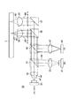
光ピックアップ装置1の光学系3は、図1に示すように、BDに対応した波長405nmのレーザ光及びDVDに対応した波長660nmのレーザ光を出射する2波長レーザダイオード10と、CDに対応した波長780nmのレーザ光を出射する1波長レーザダイオード11と、2波長レーザダイオード10から出射されたレーザ光を各波長によって所定の発散角に変換する第1のコリメータレンズ12と、1波長レーザダイオード11から出射されたレーザ光を所定の発散角に変換する第2のコリメータレンズ13と、波長780nmのレーザ光を透過させるとともに波長405nmのレーザ光及び波長660nmのレーザ光を波長780nmのレーザと同一の光路上に反射させる第1のビームスプリッタ15と、波長405nmのレーザ光を光ディスク2側へ立ち上げ、波長660nmのレーザ光及び波長780nmのレーザ光を透過させる第2のビームスプリッタ16と、波長660nmのレーザ光及び波長780nmのレーザ光を光ディスク2側へ立ち上げる立ち上げミラー17と、波長405nmのレーザ光を光ディスク2の信号記録面に収束させる第1の対物レンズ18と、波長660nmのレーザ光及び波長780nmのレーザ光を光ディスク2の信号記録面に収束させる第2の対物レンズ19と、光ディスク2からの戻りのレーザ光を検出するフォトディテクタ23と、戻りのレーザ光をフォトディテクタ23側に反射させる偏光ビームスプリッタ24を有する。
As shown in FIG. 1, the
2波長レーザダイオード10は、一つのパッケージ内にレーザ光の発光部となる2つの半導体レーザチップが数μm〜数100μm隔てて内蔵されている。一の発光部からはBDに対応した波長405nmのレーザ光が出射され、他の発光部からはDVDに対応した波長660nmのレーザ光が出射される。2波長レーザダイオード10から出射されたレーザ光は、光路上に設けられた第1のコリメータレンズ12に入射され、この第1のコリメータレンズ12により各波長に応じた有効角範囲の光がコリメートされて、第1のビームスプリッタ15へ出射される。
The two-
1波長レーザダイオード11は、一つのパッケージ内にレーザ光の発光部となる1つの半導体レーザチップが内蔵されている。この発光部からはCDに対応した波長780nmのレーザ光が出射される。1波長レーザダイオード11から出射されたレーザ光は、光路上に設けられた第2のコリメータレンズ13に入射され、この第2のコリメータレンズ13により所定の有効角範囲の光がコリメートされて第1のビームスプリッタ15へ出射される。
The one-wavelength laser diode 11 includes one semiconductor laser chip that serves as a laser light emitting part in one package. From this light emitting portion, a laser beam having a wavelength of 780 nm corresponding to the CD is emitted. The laser light emitted from the one-wavelength laser diode 11 is incident on a
第1のビームスプリッタ15は、波長分離特性を有し、波長780nmのレーザ光を透過するとともに、波長405nmのレーザ光又は波長660nmのレーザ光を反射するようになされている。これにより光学系3は、波長405nmのレーザ光、波長660nmのレーザ光及び波長780nm波長のレーザ光の光路を共通化させる。
The
第1のビームスプリッタ15を透過又は反射されたレーザ光の光路上には、後述するフォトディテクタ23へ戻りのレーザ光を入射させる偏光ビームスプリッタ24、第2のビームスプリッタ16及び立ち上げミラー17が配設されている。第2のビームスプリッタ16は、第1のビームスプリッタ15を反射した波長405nmのレーザ光を光ディスク2側へ立ち上げて第1の対物レンズ18へ入射させ、また光ディスク2からの戻りのレーザ光を偏光ビームスプリッタ24側へ反射させる。また第2のビームスプリッタ16は、第1のビームスプリッタ15を反射した波長660nmのレーザ光及び第1のビームスプリッタ15を透過した波長780nmのレーザ光を透過させて立ち上げミラー17へ入射させ、また、立ち上げミラー17によって反射された戻りのレーザ光を偏光ビームスプリッタ24側へ透過する。
On the optical path of the laser light transmitted or reflected by the
立ち上げミラー17は、第2のビームスプリッタ16を透過した波長660nmのレーザ光及び波長780nmのレーザ光を光ディスク2側へ立ち上げて第2の対物レンズ19へ入射させ、また光ディスク2からの戻りのレーザ光を偏光ビームスプリッタ24側へ反射させる。
The rising
第1の対物レンズ18は、絞り20等の開口制限手段が設けられることにより、第2のビームスプリッタ16より立ち上げられた波長405nmのレーザ光が光ディスク2の信号記録面で光スポットを形成可能な開口数とされている。また第2の対物レンズ19は、絞り21及び、対物レンズ19上に設けられた図示しない開口制限手段により、立ち上げミラー17により立ち上げられた波長660nmのレーザ光及び波長780nmのレーザ光が光ディスク2の信号記録面で光スポットを形成可能な開口数とされている。
The first
第2のビームスプリッタ16と第1の対物レンズ18との間、及び立ち上げミラー17と第2の対物レンズ19との間には、レーザ光の偏光を直線偏光から円偏光に変える1/4波長板22a、22bが設けられている。1/4波長板22a、22bは、レーザ光の偏光方向を往路と復路で互いに90°変換させることにより、同一光路を通る往路のレーザ光と復路のレーザ光との干渉を防止するとともに、復路のレーザ光を偏光ビームスプリッタ24でフォトディテクタ23側へ反射可能とする。
Between the
戻りのレーザ光を検出するフォトディテクタ23は、3波長共通の受光素子として形成されているものであり、偏光ビームスプリッタ24によって反射された戻りのレーザ光が、調整レンズ25に入射し、この調整レンズ25によって受光面に集光される。
The
戻りのレーザ光をフォトディテクタ23側に反射させる偏光ビームスプリッタ24は、往路において第1のビームスプリッタ15より出射された波長780nm、660nm及び405nmのレーザ光をほぼP偏光として透過するとともに、1/4波長板22a,22bを介して偏光方向が往路と直交する方向に変換され、第2のビームスプリッタ16及び立ち上げミラー17より反射された戻りのレーザ光を、ほぼS偏光としてフォトディテクタ23側へ全光量反射する。
The
以上のような光ピックアップ装置1の光学系3によれば、2波長レーザダイオード10から出射された波長405nmのレーザ光は、第1のコリメータレンズ12、第1のビームスプリッタ15、第2のビームスプリッタ16及び第1の対物レンズ18を経て光ディスク2の信号記録面に入射される。そして波長405nmのレーザ光は、第1のコリメータレンズ12及び第1の対物レンズ18を通る第1の光路26を経ることにより、BDの信号記録面に光スポットを結ぶように屈折される。また、2波長レーザダイオード10から出射された波長660nmのレーザ光は、第1のコリメータレンズ12、第1のビームスプリッタ15、立ち上げミラー17及び第2の対物レンズ19を経て光ディスク2の信号記録面に入射される。そして波長660nmのレーザ光は、第1のコリメータレンズ12及び第2の対物レンズ19を通る第2の光路27を経ることにより、DVDの信号記録面に光スポットを結ぶように屈折される。さらに、1波長レーザダイオード11から出射された波長780nmのレーザ光は、第2のコリメータレンズ13、第1のビームスプリッタ15、立ち上げミラー17及び第2の対物レンズ19を経て光ディスク2の信号記録面に入射される。そして波長780nmのレーザ光は、第2のコリメータレンズ13及び第2の対物レンズ19を通る第3の光路28を経ることにより、CDの信号記録面に光スポットを結ぶように屈折される。
According to the
すなわち、本発明が適用された光学系3は、2つのレーザダイオード及びコリメータレンズと、2つの対物レンズを用いて、BD、DVD、CDとフォーマットの異なる3つの光ディスク2に対応して出射された波長405nm、660nm、780nmの各レーザ光に対して、それぞれ最適な倍率を有する光学経路を形成するものである。これにより光学系3は、各波長のレーザ光に対応した光学経路を共通化させることができ、ピックアップ光学系の光路の長大化を招くことなく、各光ディスクに対応した波長のレーザ光を発光するレーザダイオードと各光ディスクとの間で、各ディスクフォーマットに最適な光学倍率を持つ光学系を実現することができる。
That is, the
係る光学系3において、各波長のレーザ光が経由する第1〜第3の光路26〜28を構成する第1、第2のコリメータレンズ12,13及び第1、第2の対物レンズ18,19は、波長405nmのレーザ光が第1の光路26を通ることによりBD記録に最適な光学倍率を有し、且つ波長660nmのレーザ光が第2の光路27を通ることによりDVD記録に最適な光学倍率を有し、且つ波長780nmのレーザ光が第3の光路28を通ることによりCD記録に最適な光学倍率を有するような倍率を備える。
In the
この各波長における倍率Mは、第1又は第2のコリメータレンズ12,13の焦点距離FC1又はFC2と、第1又は第2の対物レンズ18,19の焦点距離FOBJ1又はFOBJ2との比(M=FC/FOBJ)で表される。これよりBD記録用の波長405nmのレーザ光が通る第1の光路26の最適倍率MBは、MB=FC1/FOBJ1となり、DVD記録用の波長660nmのレーザ光が通る第2の光路27の最適倍率MDは、MD=FC1/FOBJ2となり、CD記録用の波長780nmのレーザ光が通る第3の光路28の最適倍率MCは、MC=FC2/FOBJ2となる。
The magnification M at each wavelength is the focal length F C1 or F C2 of the first or
例えば、この光学系3において、先に述べたような、レーザ側の有効角と対物レンズの開口数NAとの関係から、BD、DVD、CDそれぞれに最適な往路倍率MB、MD、MCがそれぞれ10倍、6倍、4倍であると想定した場合、かかる最適倍率を備えるような第1、第2のコリメータレンズ12,13の焦点距離及び第1、第2の対物レンズ18,19の焦点距離の一つの例として、以下の表に示すものがある。
For example, in the

この表1の関係について説明する。まず波長405nmのレーザ光が通る第1の光路26がBD記録に最適な倍率10倍を満たすように、第1の光路26を構成する第1のコリメータレンズ12の焦点距離FC1を15、第1の対物レンズ18の焦点距離FOBJ1を1.5と選定する(10=15/1.5)。
The relationship of Table 1 will be described. First, the focal length F C1 of the
DVD記録用の波長660nmのレーザ光が通る第2の光路27を構成する第1のコリメータレンズ12の焦点距離FC1は上記より15であり、DVDにおける倍率を6倍と設定することから、第2の対物レンズ19の焦点距離FOBJ2は15/6=2.5となる。
Since the focal length F C1 of the
次に、CD記録用の波長780nmのレーザ光が通る第3の光路28を構成する第2の対物レンズ19の焦点距離FOBJ2は上記より2.5であり、CDにおける倍率を4倍と設定することから、第2のコリメータレンズ13の焦点距離FC2は2.5×4=10となる。
Next, the focal length F OBJ2 of the second
これは、光学系3では、第1のコリメータレンズ12が波長405nmのレーザ光及び波長660nmのレーザ光と共通とされている一方で、波長405nmのレーザ光が入射される第1の対物レンズ18とは別に波長660nmのレーザ光が入射される第2の対物レンズ19を備える。そして第2の対物レンズ19は、DVD記録に最適な倍率を構成するために、上述した図9におけるコリメータレンズ及び対物レンズともに3波共通とされた光学系の1.7倍のレーザ側有効角を有し(倍率が1.7分の1)、これはコリメータ共通とした場合、対物レンズの焦点距離が2.5/1.5=1.7倍になることによるものである。
In the
また、光学系3では、第2の対物レンズ19が波長660nmのレーザ光及び波長780nmのレーザ光の共通とされている一方で、波長405nmのレーザ光及び波長660nmのレーザ光が入射される第1のコリメータレンズ12とは別に波長780nmのレーザ光が入射される第2のコリメータレンズ13を備える。そして、第2のコリメータレンズ13及び第2の対物レンズ19は、CD記録に最適な倍率を構成するために、上述した図9におけるコリメータレンズ及び対物レンズともに3波共通とされた光学系の2.5倍のレーザ側有効角を有し(倍率が2.5分の1)、これは、コリメータの焦点距離が、10/15=1.5分の1、対物レンズの焦点距離が2.5/1.5=1.7倍より、1.7×(1.5分の1)=2.5倍となることによるものである。
In the
以上のような光学倍率を備える第1、第2のコリメータレンズ12,13及び第1、第2の対物レンズ18,19によって上述した第1〜第3の光路26〜28を構成するような光学系3によれば、光路長の長大化ピックアップ光学系の大型化を招くことなく、2つのレーザダイオード10,11と2つの対物レンズ18,19の間に3つのフォーマットに対応した3つの光学倍率を構成する光路を実現することができる。これにより、各フォーマットの光学系における光学倍率を最適なものとし、各波長のレーザ光を各フォーマットの光ディスク上に最適な光量で集光することができる。よって、特に情報信号の記録時における記録スピードの低下等の不都合を防止できるとともに、簡単な構成で最適な記録光量による記録特性の維持を図り、所望の記録スピードを実現できる。
The first to third
なお、この光学系3において、戻りのレーザ光を波長に応じて複数のフォトディテクタで検出する場合は、図2に示すように、偏光ビームスプリッタ24と調整レンズ25との間にさらに調整レンズ及びビームスプリッタを介してフォトディテクタ29を配設し、例えば波長405nmの戻りのレーザ光はフォトディテクタ23で、波長660nm及び780nmの戻りのレーザ光はフォトディテクタ29で検出するようにしてもよい。
In this
また、本発明が適用された光ピックアップ装置の光学系は、上述した波長405nmのレーザ光と波長660nmのレーザ光とを一の2波長レーザダイオードより出射させ、波長660nmのレーザ光及び波長780nmのレーザ光を一の対物レンズに入射させる場合のみならず、波長660nmのレーザ光及び波長780nmのレーザ光を一の2波長レーザダイオードより出射させ、波長405nmのレーザ光及び波長660nmのレーザ光を一の対物レンズに入射させるようにしてもよい。 Further, an optical system of an optical pickup device to which the present invention is applied emits the laser light having a wavelength of 405 nm and the laser light having a wavelength of 660 nm from one two-wavelength laser diode, and the laser light having a wavelength of 660 nm and the laser light having a wavelength of 780 nm. In addition to the case where laser light is incident on one objective lens, laser light having a wavelength of 660 nm and laser light having a wavelength of 780 nm are emitted from a single two-wavelength laser diode, and laser light having a wavelength of 405 nm and laser light having a wavelength of 660 nm are combined. It may be made to enter the objective lens.
すなわち、この光学系30は、図3に示すように、BDに対応した波長405nmのレーザ光を出射する1波長レーザダイオード31と、DVDに対応した波長660nmのレーザ光及びCDに対応した波長780nmのレーザ光を出射する2波長レーザダイオード32と、1波長レーザダイオード31から出射されたレーザ光を所定の発散角に変換する第1のコリメータレンズ33と、2波長レーザダイオード32から出射されたレーザ光を各波長によって所定の発散角に変換する第2のコリメータレンズ34と、波長660nmのレーザ光及び波長780nmのレーザ光を透過させると共に波長405nmのレーザ光を波長660nm及び780nmのレーザ光と同一の光路上に反射させる第1のビームスプリッタ35と、波長405nmのレーザ光及び波長660nmのレーザ光を光ディスク2側へ立ち上げ、波長780nmのレーザ光を透過させる第2のビームスプリッタ36と、波長780nmのレーザ光を光ディスク2側へ立ち上げる立ち上げミラー37と、波長405nmのレーザ光及び波長660nmのレーザ光を光ディスク2の信号記録面に収束させる第1の対物レンズ38と、波長780nmのレーザ光を光ディスク2の信号記録面に収束させる第2の対物レンズ39と、光ディスク2からの戻りのレーザ光を検出するフォトディテクタ40と、戻りのレーザ光をフォトディテクタ40側に反射させる偏光ビームスプリッタ42を有する。
That is, as shown in FIG. 3, the
この光学系30においても、上記光学系3と同様に、第1の対物レンズ38の直前に設けられた絞り43及び対物レンズ38上に設けられた図示しない開口制限手段により、第2のビームスプリッタ36により立ち上げられた波長405nm及び波長660nmのレーザ光が光ディスク2の信号記録面で光スポットを形成可能な開口数とされている。また第2の対物レンズ39の直前にも、絞り44等の開口制限手段が設けられ、立ち上げミラー37により立ち上げられた波長780nmのレーザ光が光ディスク2の信号記録面で光スポットを形成可能な開口数とされている。
Also in the
また、戻りのレーザ光を検出するフォトディテクタ40と偏光ビームスプリッタ42との間には調整レンズ45が配設され、この調整レンズ45によって戻りのレーザ光がフォトディテクタ40の受光面に集光される。
An adjusting
また、第2のビームスプリッタ36と第1の対物レンズ38との間、及び立ち上げミラー37と第2の対物レンズ39との間には、レーザ光の偏光を直線偏光から円偏光に変える1/4波長板41a、41bが設けられている。1/4波長板41a、41bは、レーザ光の偏光方向を往路と復路で互いに90°変換させることにより、同一光路を通る往路のレーザ光と復路のレーザ光との干渉を防止するとともに、復路のレーザ光を偏光ビームスプリッタ42でフォトディテクタ40側へ反射可能とする。
Further, between the
以上のような光学系30によれば、1波長レーザダイオード31から出射された波長405nmのレーザ光は、第1のコリメータレンズ33、第1のビームスプリッタ35、第2のビームスプリッタ36及び第1の対物レンズ38を経て光ディスク2の信号記録面に入射される。そして波長405nmのレーザ光は、第1のコリメータレンズ33及び第1の対物レンズ38を通る第1の光路46を経ることにより、BDの信号記録面に光スポットを結ぶように屈折される。また、2波長レーザダイオード32から出射された波長660nmのレーザ光は、第2のコリメータレンズ34、第1のビームスプリッタ35、第2のビームスプリッタ36及び第1の対物レンズ38を経て光ディスク2の信号記録面に入射される。そして波長660nmのレーザ光は、第2のコリメータレンズ34及び第1の対物レンズ38を通る第2の光路47を経ることにより、DVDの信号記録面に光スポットを結ぶように屈折される。さらに、2波長レーザダイオード32から出射された波長780nmのレーザ光は、第2のコリメータレンズ34、第1のビームスプリッタ35、立ち上げミラー37及び第2の対物レンズ39を経て光ディスク2の信号記録面に入射される。そして波長780nmのレーザ光は、第2のコリメータレンズ34及び第2の対物レンズ39を通る第3の光路48を経ることにより、CDの信号記録面に光スポットを結ぶように屈折される。
According to the
すなわち、かかる光学系30も、2つのレーザダイオード及びコリメータレンズと、2つの対物レンズを用いて、BD、DVD、CDとフォーマットの異なる3つの光ディスク2に対応して出射された波長405nm、660nm、780nmの各レーザ光に対して、それぞれ最適な倍率を有する光学経路を形成するものである。したがってこの光学系30においても、各波長のレーザ光に対応した光学経路を共通化させることができ、ピックアップ光学系の光路の長大化を招くことなく、各光ディスクに対応した波長のレーザ光を発光するレーザダイオードと各光ディスクとの間で、各ディスクフォーマットに最適な光学倍率を持つ光学系を実現することができる。
That is, the
係る光学系30において、各波長のレーザ光が経由する第1〜第3の光路46〜48を構成する第1、第2のコリメータレンズ33,34及び第1、第2の対物レンズ38,39は、波長405nmのレーザ光が第1の光路46を通ることによりBD記録に最適な光学倍率を有し、且つ波長660nmのレーザ光が第2の光路47を通ることによりDVD記録に最適な光学倍率を有し、且つ波長780nmのレーザ光が第3の光路48を通ることによりCD記録に最適な光学倍率を有するような倍率を備える。
In the
上述したように、各波長における最適倍率Mは、第1又は第2のコリメータレンズ33,34の焦点距離FC1又はFC2と、第1又は第2の対物レンズ38,39の焦点距離FOBJ1又はFOBJ2との比(M=FC/FOBJ)で表される。これよりBD記録用の波長405nmのレーザ光が通る第1の光路46の最適倍率MBは、MB=FC1/FOBJ1となり、DVD記録用の波長660nmのレーザ光が通る第2の光路47の最適倍率MDは、MD=FC2/FOBJ1となり、CD記録用の波長780nmのレーザ光が通る第3の光路48の最適倍率MCは、MC=FC2/FOBJ2となる。
As described above, the optimum magnification M at each wavelength is determined by the focal length F C1 or F C2 of the first or
例えば、この光学系30において、先に述べたような、レーザ側の有効角と対物レンズの開口数NAとの関係から、BD、DVD、CDそれぞれに最適な往路倍率MB、MD、MCがそれぞれ10倍、6倍、4倍であると想定した場合、かかる最適倍率を備えるような第1、第2のコリメータレンズ33,34の焦点距離及び第1、第2の対物レンズ38,39の焦点距離の一つの例として、以下の表に示すものがある。
For example, in this
この表2の関係について説明する。まず波長405nmのレーザ光が通る第1の光路46がBD記録に最適な倍率10倍を満たすように、第1の光路46を構成する第1のコリメータレンズ33の焦点距離FC1を15、第1の対物レンズ38の焦点距離FOBJ1を1.5と選定する(10=15/1.5)。
The relationship of Table 2 will be described. First, the focal length F C1 of the
DVD記録用の波長660nmのレーザ光が通る第2の光路47を構成する第1の対物レンズ38の焦点距離FOBJ1は上記より1.5であり、DVDにおける倍率を6倍と設定することから、第2のコリメータレンズ34の焦点距離FC2は1.5×6=9となる。
The focal length F OBJ1 of the first
次に、CD記録用の波長780nmのレーザ光が通る第3の光路48を構成する第2のコリメータレンズ34の焦点距離FC2は上記より9であり、CDにおける倍率を4倍と設定することから、第2の対物レンズ39の焦点距離FOBJ2は9/4=2.25となる。
Next, the focal length F C2 of the
これは、光学系30では、第1の対物レンズ38が波長405nmのレーザ光及び波長660nmのレーザ光と共通とされている一方で、波長405nmのレーザ光が入射される第1のコリメータレンズ33とは別に波長660nm及び波長780nmのレーザ光が入射される第2のコリメータレンズ34を備える。そして第2のコリメータレンズ39は、DVD記録に最適な倍率を構成するために、上述した図9におけるコリメータレンズ及び対物レンズともに3波共通とされた光学系の1.7倍のレーザ側有効角を有し(倍率が1.7分の1)、これは対物レンズ共通とした場合、コリメータレンズの焦点距離が15/9=1.7倍になることによるものである。
In the
また、光学系3では、第2のコリメータレンズ34が波長660nmのレーザ光及び波長780nmのレーザ光の共通とされている一方で、波長405nmのレーザ光及び波長660nmのレーザ光が入射される第1の対物レンズ38とは別に波長780nmのレーザ光が入射される第2の対物レンズ39を備える。そして、第2のコリメータレンズ34及び第2の対物レンズ39は、CD記録に最適な倍率を構成するために、上述した図9におけるコリメータレンズ及び対物レンズともに3波共通とされた光学系の2.5倍のレーザ側有効角を有し(倍率が2.5分の1)、これは、対物レンズの焦点距離が、2.25/1.5=1.5、コリメータレンズの焦点距離が15/9=1.7倍より、1.7×(1.5)=2.5倍となることによるものである。
In the
以上のような光学倍率を備える第1、第2のコリメータレンズ33,34及び第1、第2の対物レンズ38,39によって上述した第1〜第3の光路46〜48を構成するような光学系30によれば、光路長の長大化やピックアップ光学系の大型化を招くことなく、2つのレーザダイオード31,32と2つの対物レンズ38,39の間に3つのフォーマットに対応した3つの光学倍率を構成する光路を実現することができる。
The first to third
なお、この光学系30においても、戻りのレーザ光を波長に応じて複数のフォトディテクタで検出する場合は、上記図2に示すように、偏光ビームスプリッタ42と調整レンズ45との間にさらに調整レンズ及びビームスプリッタを配設するようにしてもよい。
In this
次いで、本発明が適用された光ピックアップ装置1の実施例について説明する。この光ピックアップ装置1は、図4に示すように、光ディスク2の径方向に配された一対のガイド軸51,52に支持されたピックアップベース53を備え、このピックアップベース53内に光学系54が形成されている。光学系54は、BDに対応した波長405nmのレーザ光及びDVDに対応した波長660nmのレーザ光を出射する2波長レーザダイオード55と、CDに対応した波長780nmのレーザ光を出射する1波長レーザダイオード56と、波長選択性を有する第1、第2の偏光ビームスプリッタ57,58と、レーザ光の光軸方向に移動可能に支持されたコリメータレンズ59と、波長405nmのレーザ光を光ディスク2側へ反射すると共に波長660nm及び780nmのレーザ光を透過するビームスプリッタ60と、波長660nm及び780nmのレーザ光を光ディスク2側へ立ち上げる立ち上げミラー61と、ビームスプリッタ60によって立ち上げられた波長405nmのレーザ光をBDの信号記録面に収束させる第1の対物レンズ62と、立ち上げミラー61によって立ち上げられた波長660nm及び780nmのレーザ光をDVD又はCDの信号記録面に収束させる第2の対物レンズ63と、第2の偏光ビームスプリッタ58によって反射された波長405nmの戻りのレーザ光を検出する第1のフォトディテクタ64と、第1の偏光ビームスプリッタ57を透過した波長660nm及び780nmの戻りのレーザ光を検出する第2のフォトディテクタ65とを有する。
Next, an embodiment of the
この光学系54に用いられる波長選択性を有する第1及び第2の偏光ビームスプリッタ57,58は、入射されたレーザ光の波長によって透過又は反射させるものであり、例えば所定の構成を有する光学薄膜をプリズムの接合面に設けることにより形成される。具体的に第1の偏光ビームスプリッタ57は、波長405nmのレーザ光を反射し、波長780nmのレーザ光を透過し、且つ波長660nmのレーザ光を偏光状態に応じて透過又は反射させるものである。また第2の偏光ビームスプリッタ58は、波長660nmのレーザ光及び波長780nmのレーザ光を透過し、且つ波長405nmのレーザ光を偏光状態に応じて透過又は反射させるものである。
The first and second
また、この光学系54では、2つのコリメータレンズを備える代わりに、3波長で共通のコリメータレンズ59及び、このコリメータレンズ59と組み合わされることによりCD光路のみ合成焦点距離を短縮するカップリングレンズ66aを780nmのレーザ光を出射する1波長レーザダイオード56が収納されたCDLDパッケージ66に接合した構成をとっている。
Further, in this
また、2波長レーザダイオード55は、660nmのレーザ光に対する半波長板機能を兼ね備えたグレーティングが形成されたパッケージに収納されている。
The two-
なお、光軸方向に移動自在に支持されたコリメータレンズ59は、レンズホルダ67の両端が、光軸方向に延設された一対のガイド軸68,69に挿通支持されるとともに、駆動モータ70の回転軸71に係合されている。そしてレンズホルダ67が光軸方向に移動されることにより、コリメータレンズ59は、BD及びDVDにおける球面収差を補正することができる。
The
以上のような光学系54では、2波長レーザダイオード55より出射された波長405nmのレーザ光は、所定の焦点距離に設定されたコリメータレンズ59及び第1の対物レンズ62を通る第1の光路を通り、2波長レーザダイオード55より出射された波長660nmのレーザ光は、所定の焦点距離に設定されたコリメータレンズ59及び第2の対物レンズ63を通る第2の光路を通り、1波長レーザダイオード56より出射された波長780nmのレーザ光は、CDLDパッケージ66に設けられたカップリングレンズ66a、所定の焦点距離に設定されたコリメータレンズ59及び第2の対物レンズ63を通る第3の光路を通ることにより、3つのディスクフォーマットに対応した3つの光学倍率を備える光路を構成する。
In the
すなわち、2波長レーザダイオード55より出射された波長405nmのレーザ光は、660nmのレーザ光に対する半波長板機能を兼ね備えたグレーティングにより、差動プッシュプル法によりトラッキングエラーを生成するための3つのビームに分岐され、第1の偏光ビームスプリッタ57でほぼ全光量反射され、405nmのレーザ光に対してのみ半波長板として作用する波長板によって、偏光方向を所定量回転されて、第2の偏光ビームスプリッタ58を一部透過、一部反射する。第2の偏光ビームスプリッタ58を透過したレーザ光は、予め表1に示す光学倍率を構成するような焦点距離に設定されたコリメータレンズ59を透過し、ビームスプリッタ60によって光ディスク2側へ反射され、第1の対物レンズ62に入射される。また第2の偏光ビームスプリッタ58を透過したレーザ光はレーザパワーをモニタするためのフォトディテクタ73に検出される。
That is, the laser beam having a wavelength of 405 nm emitted from the two-
かかる波長405nmのレーザ光が通る第1の光路は、コリメータレンズ59及び第1の対物レンズ62が例えば上記表1に示すような焦点距離に設定されることによりBD記録に最適な光学倍率を備えた光路とされるため、波長405nmのレーザ光が適切な光量にてBDの信号記録面に照射される。
The first optical path through which the laser beam having a wavelength of 405 nm passes has an optical magnification optimum for BD recording by setting the
BDに反射された戻りのレーザ光は、ビームスプリッタ60によって反射され、コリメータレンズ59を透過して、第2の偏光ビームスプリッタ58によって第1のフォトディテクタ64側に反射される。そして戻りのレーザ光は調整レンズ74によって第1のフォトディテクタ64の受光面に集光される。
The return laser light reflected by the BD is reflected by the
また、2波長レーザダイオード55より出射された波長660nmのレーザ光は、660nmのレーザ光に対する半波長板機能を兼ね備えたグレーティングにより、偏光方向を偏光ビームスプリッタに対してほぼS偏光となるように回転されるとともに、差動プッシュプル法によりトラッキングエラーを生成するための3つのビームに分岐され、第1の偏光ビームスプリッタ57によって全光量反射される。第1の偏光ビームスプリッタ57に反射されたレーザ光は、第2の偏光ビームスプリッタ58を透過し、予め表1に示す光学倍率を構成するような焦点距離に設定されたコリメータレンズ59及びビームスプリッタ60を透過して、ハーフミラー機能を有する立ち上げミラー61によって第2の対物レンズ63に入射される。また、レーザ光は立ち上げミラー61を一部透過してレーザパワーをモニタするためのフォトディテクタ75に検出される。
The laser beam having a wavelength of 660 nm emitted from the two-
かかる波長660nmのレーザ光が通る第2の光路は、コリメータレンズ59及び第2の対物レンズ63が例えば上記表1に示すような焦点距離に設定されることによりDVD記録に最適な光学倍率を備えた光路とされるため、波長660nmのレーザ光が適切な光量にてDVDの信号記録面に照射される。
The second optical path through which the laser beam having a wavelength of 660 nm passes has an optical magnification optimum for DVD recording by setting the
DVDに反射された戻りのレーザ光は、立ち上げミラー61に反射され、コリメータレンズ59、第2の偏光ビームスプリッタ58、第1の偏光ビームスプリッタ57及びハーフミラー76を透過して第2のフォトディテクタ65に検出される。
The return laser beam reflected by the DVD is reflected by the rising
また、1波長レーザダイオード56より出射された波長780nmのレーザ光は、CDLDパッケージ66に固定されたカップリングレンズ66aによりコリメータレンズ59と組み合わせた合成焦点距離を短縮されるとともに、ハーフミラー76によって反射され、第1の偏光ビームスプリッタ57、波長板及び第2の偏光ビームスプリッタ58を透過し、カップリングレンズ66aと組み合わされることにより上記表1に示す光学倍率を構成するような焦点距離に設定されたコリメータレンズ59に入射する。そして、このレーザ光はコリメータレンズ59及びビームスプリッタ60を透過して立ち上げミラー61によって第2の対物レンズ63に入射される。また、レーザ光は立ち上げミラー61を一部透過してレーザパワーをモニタするためのフォトディテクタ75に検出される。
The laser beam having a wavelength of 780 nm emitted from the one-
かかる波長780nmのレーザ光が通る第3の光路は、カップリングレンズ66aと組み合わされたコリメータレンズ59及び第2の対物レンズ63が上述したような焦点距離に設定されることにより、CD記録に最適な光学倍率を備えた光路とされるため、波長780nmのレーザ光が適切な光量にてCDの信号記録面に照射される。
The third optical path through which the laser light having a wavelength of 780 nm passes is optimal for CD recording by setting the
CDに反射された戻りのレーザ光は、立ち上げミラー61に反射され、コリメータレンズ59、第2の偏光ビームスプリッタ58、第1の偏光ビームスプリッタ57及びハーフミラー76を透過して第2のフォトディテクタ65に検出される。
The return laser beam reflected by the CD is reflected by the rising
次いで、本発明が適用された光ピックアップ装置1の他の実施例について説明する。この光ピックアップ装置1は、波長660nmのレーザ光及び波長780nmのレーザ光を出射する2波長半導体レーザと、これらレーザ光の光ディスク2からの反射光を受光するフォトディテクタがハイブリッドに集積されたいわゆるレーザカプラを用いて光学系80を構成したものであり、図5に示すように、光ディスク2の径方向に配された一対のガイド軸81,82に支持されたピックアップベース83を備え、このピックアップベース83内に光学系80が形成されている。光学系80は、BDに対応した波長405nmのレーザ光のレーザ光を出射する1波長レーザダイオード85と、CDに対応した波長780nmのレーザ光及びDVDに対応した波長660nmの受発光素子が搭載されたレーザカプラ86と、波長選択性を有する第1、第2の偏光ビームスプリッタ87,88と、レーザ光の光軸方向に移動可能に支持されたコリメータレンズ89と、波長405nmのレーザ光及び波長660nmのレーザ光を光ディスク2側へ反射すると共に波長780nmのレーザ光を透過するビームスプリッタ90と、波長780nmのレーザ光を光ディスク2側へ立ち上げる立ち上げミラー91と、ビームスプリッタ90によって立ち上げられた波長405nm及び660nmのレーザ光をBD又はDVDの信号記録面に収束させる第1の対物レンズ92と、立ち上げミラー91によって立ち上げられた波長780nmのレーザ光をCDの信号記録面に収束させる第2の対物レンズ93と、第1の偏光ビームスプリッタ87によって反射された波長405nmの戻りのレーザ光を検出するフォトディテクタ94とを有する。
Next, another embodiment of the
この光学系80に用いられるレーザカプラ86は、図6に示すように、表面領域に光検出用のフォトディテクタ101,102が設けられたシリコンチップ103上に、波長660nmのレーザ光及び波長780nmのレーザ光の発光源である2波長レーザダイオード104とプリズム105が取り付けられたレーザカプラチップ106を、例えば、フラットパッケージ107内に収容して構成されている。
As shown in FIG. 6, a
2波長レーザダイオード104は、通常、表面領域にPINフォトダイオード108が設けられたフォトダイオードチップ109を介してシリコンチップ103に取り付けられる。このフォトダイオードチップ109に設けられたPINフォトダイオード108は、2波長レーザダイオード104の出力を制御する目的で、その2波長レーザダイオード104の後面から出射するレーザ光をモニターする。
The two-
2波長レーザダイオード104の前面から出射した出射光は、プリズム105の傾斜端面105aでほぼ直角に反射され、フラットパッケージ107上面の透明カバーガラスを通して、図5に示すように、コリメータレンズ89及び第1又は第2の対物レンズ92,93から光ディスク2の信号記録面に導かれる。一方、光ディスク2の信号記録面で反射した戻り光は、光ディスク2及びフラットパッケージ107との間を同一経路で進んでフラットパッケージ107内へ入射され、プリズム105の傾斜端面105aを透過したレーザ光がプリズム105内を通ってフォトディテクタ101,102により検出される。
The outgoing light emitted from the front surface of the two-
また、この光学系80に用いられる波長選択性を有する第1及び第2の偏光ビームスプリッタ87,88は、入射されたレーザ光の波長によって透過又は反射させるものであり、例えば所定の構成を有する光学薄膜をプリズムの接合面に設けることにより形成される。具体的に第1、第2の偏光ビームスプリッタ87,88は、波長660nmのレーザ光及び波長780nmのレーザ光を透過し、且つ波長405nmのレーザ光を偏光状態に応じて透過又は反射させるものである。
Further, the first and second
また、この光学系80でも、2つのコリメータレンズを備える代わりに、3波長で共通のコリメータレンズ89及び、このコリメータレンズ89と組み合わされることによりDVD/CD光路のみ合成焦点距離を短縮するカップリングレンズ110をレーザカプラ86に隣接して配置した構成をとっている。
Also in this
また、1波長レーザダイオード85は、405nmのレーザ光に対する半波長板機能を兼ね備えたグレーティングが形成されたパッケージに収納されている。
The one-
なお、光軸方向に移動自在に支持されたコリメータレンズ89は、レンズホルダ95の両端が、光軸方向に延設された一対のガイド軸96,97に挿通支持されるとともに、駆動モータ98の回転軸99に係合されている。そしてレンズホルダ95が光軸方向に移動されることにより、コリメータレンズ89は、BDにおける球面収差を補正することができる。
In the
以上のような光学系80では、1波長レーザダイオード85より出射された波長405nmのレーザ光は、所定の焦点距離に設定されたコリメートレンズ69及び第1の対物レンズ92を通る第1の光路を通り、レーザカプラ86から出射された波長660nmのレーザ光は、所定の焦点距離に設定されたコリメータレンズ89及び第1の対物レンズ92を通る第2の光路を通り、レーザカプラ86から出射された波長780nmのレーザ光は、所定の焦点距離に設定されたコリメータレンズ89及び第2の対物レンズ72を通る第3の光路を通ることにより、3つのディスクフォーマットに対応した3つの光学倍率を備える光路を構成する。
In the
すなわち、1波長レーザダイオード85より出射された波長405nmのレーザ光は、半波長板機能を兼ね備えたグレーティングによって、偏光方向を所定量回転されるとともに、差動プッシュプル法によってトラッキングエラー信号を生成するための3つのビームに分岐されて、第1の偏光ビームスプリッタ87を全光量反射し、第2の偏光ビームスプリッタ88を一部透過、一部反射する。第2の偏光ビームスプリッタ88を透過したレーザ光は、予め表2に示すような第1の対物レンズ92と共にBD記録に最適な光学倍率を構成するような焦点距離に設定されたコリメータレンズ89を透過し、ビームスプリッタ90によって光ディスク2側へ反射され、第1の対物レンズ92に入射される。また第2の偏光ビームスプリッタ88を透過したレーザ光はレーザパワーをモニタするためのフォトディテクタ111に検出される。
That is, the laser beam having a wavelength of 405 nm emitted from the one-
かかる波長405nmのレーザ光が通る第1の光路は、コリメータレンズ89及び第1の対物レンズ92が例えば上記表2に示すような焦点距離に設定されることによりBD記録に最適な光学倍率を備えた光路とされるため、波長405nmのレーザ光が適切な光量にてBDの信号記録面に照射される。
The first optical path through which the laser beam having a wavelength of 405 nm passes has an optical magnification optimum for BD recording by setting the
BDに反射された戻りのレーザ光は、ビームスプリッタ90によって反射され、コリメータレンズ89及び第2の偏光ビームスプリッタ88を透過して、波長405nmのレーザ光のみに半波長板として作用する波長板により偏光方向を90度回転されて、第1の偏光ビームスプリッタ87によってフォトディテクタ94側に反射される。そして戻りのレーザ光は調整レンズ112及びミラー113を介してフォトディテクタ94の受光面に集光される。
The return laser beam reflected by the BD is reflected by the
また、レーザカプラ86より出射された波長660nmのレーザ光は、第1、第2の偏光ビームスプリッタ87,88を透過して、カップリングレンズ110と組み合わされることにより上記表2に示すような第1の対物レンズ92と共にDVD記録に最適な光学倍率を構成するような焦点距離に設定されたコリメータレンズ89を透過し、ビームスプリッタ90によって光ディスク2側へ反射され、第1の対物レンズ92に入射される。
Further, the laser light having a wavelength of 660 nm emitted from the
かかる波長660nmのレーザ光が通る第2の光路は、カップリングレンズ110と組み合わされたコリメータレンズ89及び第1の対物レンズ92が例えば上記表2に示すような焦点距離に設定されることによりDVD記録に最適な光学倍率を備えた光路とされるため、波長660nmのレーザ光が適切な光量にてDVDの信号記録面に照射される。
The second optical path through which the laser light having a wavelength of 660 nm passes is set such that the
DVDに反射された戻りのレーザ光は、ビームスプリッタ90によって反射され、コリメータレンズ89、第2の偏光ビームスプリッタ88及び第1の偏光ビームスプリッタ87を透過して、レーザカプラ86内に入射する。そして戻り光は、プリズム105の傾斜端面105aを透過しプリズム105内を通ってフォトディテクタ101,102により検出される。
The return laser beam reflected by the DVD is reflected by the
また、レーザカプラ86より出射された波長780nmのレーザ光は、第1、第2の偏光ビームスプリッタ87,88を透過して、カップリングレンズ110と組み合わされることにより上記表2に示すような第2の対物レンズ93と共にCD記録に最適な光学倍率を構成するような焦点距離に設定されたコリメータレンズ89及びビームスプリッタ90を透過し、立ち上げミラー91によって反射され第2の対物レンズ93に入射される。
Further, the laser beam having a wavelength of 780 nm emitted from the
かかる波長780nmのレーザ光が通る第3の光路は、カップリングレンズ110と組み合わされたコリメータレンズ89及び第2の対物レンズ93が例えば上記表2に示すような焦点距離に設定されることによりCD記録に最適な光学倍率を備えた光路とされるため、波長780nmのレーザ光が適切な光量にてCDの信号記録面に照射される。
The third optical path through which the laser light having a wavelength of 780 nm passes is set such that the
CDに反射された戻りのレーザ光は、立ち上げミラー91によって反射され、コリメータレンズ89、第2の偏光ビームスプリッタ88及び第1の偏光ビームスプリッタ87を透過して、レーザカプラ86内に入射する。そして戻り光は、プリズム105の傾斜端面105aを透過しプリズム105内を通ってフォトディテクタ101,102により検出される。
The return laser light reflected by the CD is reflected by the rising
以上は、レーザ光がレーザダイオードから光ディスクに向かう往路における光路倍率に着目した構成であるが、本発明が適用された光ピックアップ装置は、往路における光路倍率のみならず、同時に、光ディスクに反射されたレーザ光が受光素子に向かう復路においても、3つのディスクフォーマットに適した最適な3種類の光路倍率を構成する光学系を構成することができる。なお、以下の説明においては、上述した光学系3及び光学系30において説明した部材と同一の部材については同一の符号を付してその詳細を省略する。
The above is a configuration that focuses on the optical path magnification in the forward path from the laser diode to the optical disk, but the optical pickup device to which the present invention is applied reflects not only the optical path magnification in the forward path but also the optical disk at the same time. Even in the return path of the laser beam toward the light receiving element, it is possible to configure an optical system that constitutes the optimum three types of optical path magnifications suitable for the three disk formats. In the following description, the same members as those described in the
このような光ピックアップ装置120の光学系121は、図7に示すように、BDに対応した波長405nmのレーザ光及びDVDに対応した波長660nmのレーザ光を出射する2波長レーザダイオードと、光ディスク2に反射されたこれら2つの波長のレーザ光の戻り光を検出する共通の受光素子となるフォトディテクタとが搭載された第1のレーザカプラ122と、CDに対応した波長780nmのレーザ光を出射する1波長レーザダイオードと、光ディスク2に反射された波長780nmのレーザ光の戻り光を検出する受光素子となるフォトディテクタとが搭載されたレーザカプラ123と、第1のレーザカプラ122から出射されたレーザ光を所定の発散角に変換する第1のコリメータレンズ12と、第2のレーザカプラ123から出射されたレーザ光を所定の発散角に変換する第2のコリメータレンズ13と、波長780nmのレーザ光を透過させるとともに波長405nmのレーザ光及び波長660nmのレーザ光を波長780nmのレーザと同一の光路上に反射させる第1のビームスプリッタ15と、波長405nmのレーザ光を光ディスク2側へ立ち上げ、波長660nmのレーザ光及び波長780nmのレーザ光を透過させる第2のビームスプリッタ16と、波長660nmのレーザ光及び波長780nmのレーザ光を光ディスク2側へ立ち上げる立ち上げミラー17と、波長405nmのレーザ光を光ディスク2の信号記録面に収束させる第1の対物レンズ18と、波長660nmのレーザ光及び波長780nmのレーザ光を光ディスク2の信号記録面に収束させる第2の対物レンズ19とを有する。
As shown in FIG. 7, the
第1の対物レンズ18は、絞り20等の開口制限手段が設けられることにより、第2のビームスプリッタ16より立ち上げられた波長405nmのレーザ光が光ディスク2の信号記録面で光スポットを形成可能な開口数とされている。また第2の対物レンズ19は、絞り21及び、対物レンズ19上に設けられた図示しない開口制限手段により、立ち上げミラー17により立ち上げられた波長660nmのレーザ光及び波長780nmのレーザ光が光ディスク2の信号記録面で光スポットを形成可能な開口数とされている。
The first
第2のビームスプリッタ16と第1の対物レンズ18との間、及び立ち上げミラー17と第2の対物レンズ19との間には、レーザ光の偏光を直線偏光から円偏光に変える1/4波長板22a、22bが設けられている。
Between the
以上のような光学系121によれば、第1のレーザカプラ122から出射された波長405nmのレーザ光は、第1のコリメータレンズ12、第1のビームスプリッタ15、第2のビームスプリッタ16及び第1の対物レンズ18を経て光ディスク2の信号記録面に入射し、光ディスク2の信号記録面に反射された戻りのレーザ光は、往路と同一の経路を経て第1のレーザカプラ122内へ入射し、フォトディテクタに検出される。そして、波長405nmのレーザ光は、光ディスク2に反射された戻り光が第1の対物レンズ18及び第1のコリメータレンズ12を通る第1の光路124を経ることにより、第1のレーザカプラ122のフォトディテクタの受光面に光スポットを結ぶように屈折される。
According to the
また、第1のレーザカプラ122から出射された波長660nmのレーザ光は、第1のコリメータレンズ12、第1のビームスプリッタ15、第2のビームスプリッタ16、立ち上げミラー17及び第2の対物レンズ19を経て光ディスク2の信号記録面に入射し、光ディスク2の信号記録面に反射された戻りのレーザ光は、往路と同一の経路を経て第1のレーザカプラ122内へ入射し、フォトディテクタに検出される。そして、波長660nmのレーザ光は、光ディスク2に反射された戻り光が第2の対物レンズ19及び第1のコリメータレンズ12を通る第2の光路125を経ることにより、第1のレーザカプラ122のフォトディテクタの受光面に光スポットを結ぶように屈折される。
The laser beam having a wavelength of 660 nm emitted from the
また、第2のレーザカプラ123から出射された波長780nmのレーザ光は、第2のコリメータレンズ13、第1のビームスプリッタ15、第2のビームスプリッタ16、立ち上げミラー17及び第2の対物レンズ19を経て光ディスク2の信号記録面に入射し、光ディスク2の信号記録面に反射された戻りのレーザ光は、往路と同一の経路を経て第2のレーザカプラ123内へ入射し、フォトディテクタに検出される。そして、波長780nmのレーザ光は、光ディスク2に反射された戻り光が第2の対物レンズ19及び第2のコリメータレンズ13を通る第3の光路126を経ることにより、第2のレーザカプラ123のフォトディテクタの受光面に光スポットを結ぶように屈折される。
The laser beam having a wavelength of 780 nm emitted from the
ここで、それぞれのディスクフォーマットにおけるデフォーカスマージンと深く関係する量として、それぞれの波長λ、対物レンズの開口数NAに対する、焦点深度Zがあげられる。ここで、焦点深度Z=λ/(NA2)である。一方、フォーカスエラー信号の引き込み範囲Sppは、一般的な非点収差法、スポットサイズ法の場合には、近軸領域における近似値としては、PD上スポット径φ、対物レンズの開口数NA、復路倍率βとすると、Spp=0.5×φ/(NA×β)で表される。 Here, as a quantity deeply related to the defocus margin in each disk format, there is a focal depth Z with respect to each wavelength λ and the numerical aperture NA of the objective lens. Here, the depth of focus Z = λ / (NA 2 ). On the other hand, the focus error signal pull-in range Spp is, in the case of the general astigmatism method and spot size method, as an approximate value in the paraxial region, the spot diameter φ on the PD, the numerical aperture NA of the objective lens, the return path When the magnification is β, it is expressed by Spp = 0.5 × φ / (NA × β).
BD,DVD,CDそれぞれの場合において、簡単のため、Spp=Zの4倍、φ=75μmとして、望ましい復路倍率がどうなるかを計算してみると、以下に示す表3ようになる。 In the case of each of BD, DVD, and CD, for simplicity, assuming that Spp = Z is 4 times and φ = 75 μm, the desired return magnification is calculated as shown in Table 3 below.
このように、復路における最適倍率も各波長、フォーマット毎に異なることがわかる。したがって、上記第1〜第3の光路124〜126を構成する第1、第2の対物レンズ18,19及び第1、第2のコリメータレンズ12,13も、上記表3に示す復路倍率βを実現する構成とされる。
Thus, it can be seen that the optimum magnification in the return path is also different for each wavelength and format. Therefore, the first and second
また、本発明が適用された光ピックアップ装置の光学系は、上述した波長405nmのレーザ光と波長660nmのレーザ光とを一のレーザカプラより出射させ、波長660nmのレーザ光及び波長780nmのレーザ光を一の対物レンズに入射させる場合のみならず、波長660nmのレーザ光及び波長780nmのレーザ光を一のレーザカプラより出射させ、波長405nmのレーザ光及び波長660nmのレーザ光を一の対物レンズに入射させるようにしてもよい。 An optical system of an optical pickup device to which the present invention is applied emits the laser light having a wavelength of 405 nm and the laser light having a wavelength of 660 nm from one laser coupler, and the laser light having a wavelength of 660 nm and the laser light having a wavelength of 780 nm. The laser beam having a wavelength of 660 nm and the laser beam having a wavelength of 780 nm are emitted from one laser coupler, and the laser beam having a wavelength of 405 nm and the laser beam having a wavelength of 660 nm are applied to one objective lens. You may make it enter.
すなわち、この光学系127は、図8に示すように、BDに対応した波長405nmのレーザ光を出射する1波長レーザダイオードと、光ディスク2に反射された波長405nmのレーザ光の戻り光を受光する受光素子となるフォトディテクタとが搭載された第1のレーザカプラ128と、DVDに対応した波長660nmのレーザ光及びCDに対応した波長780nmのレーザ光を出射する2波長レーザダイオードと、光ディスク2に反射された波長660nmのレーザ光及び波長780nmのレーザ光の戻り光を受光する共通の受光素子となるフォトディテクタとが搭載された第2のレーザカプラ129と、第1のレーザカプラ128から出射されたレーザ光を所定の発散角に変換する第1のコリメータレンズ33と、第2のレーザカプラ129から出射されたレーザ光を各波長によって所定の発散角に変換する第2のコリメータレンズ34と、波長660nmのレーザ光及び波長780nmのレーザ光を透過させると共に波長405nmのレーザ光を波長660nm及び780nmのレーザ光と同一の光路上に反射させる第1のビームスプリッタ35と、波長405nmのレーザ光及び波長660nmのレーザ光を光ディスク2側へ立ち上げ、波長780nmのレーザ光を透過させる第2のビームスプリッタ36と、波長780nmのレーザ光を光ディスク2側へ立ち上げる立ち上げミラー37と、波長405nmのレーザ光及び波長660nmのレーザ光を光ディスク2の信号記録面に収束させる第1の対物レンズ38と、波長780nmのレーザ光を光ディスク2の信号記録面に収束させる第2の対物レンズ39とを有する。
That is, as shown in FIG. 8, the
この光学系127においても、上記光学系121と同様に、第1の対物レンズ38の直前に設けられた絞り43及び対物レンズ38上に設けられた図示しない開口制限手段により、第2のビームスプリッタ36により立ち上げられた波長405nm及び波長660nmのレーザ光が光ディスク2の信号記録面で光スポットを形成可能な開口数とされている。また第2の対物レンズ39の直前にも、絞り44等の開口制限手段が設けられ、立ち上げミラー37により立ち上げられた波長780nmのレーザ光が光ディスク2の信号記録面で光スポットを形成可能な開口数とされている。
Also in the
また、第2のビームスプリッタ36と第1の対物レンズ38との間、及び立ち上げミラー37と第2の対物レンズ39との間には、レーザ光の偏光を直線偏光から円偏光に変える1/4波長板41a、41bが設けられている。
Further, between the
以上のような光学系127によれば、第1のレーザカプラ128から出射された波長405nmのレーザ光は、第1のコリメータレンズ33、第1のビームスプリッタ35、第2のビームスプリッタ36及び第1の対物レンズ38を経て光ディスク2の信号記録面に入射し、光ディスク2の信号記録面に反射された戻りのレーザ光は、往路と同一の経路を経て第1のレーザカプラ128内へ入射し、フォトディテクタに検出される。そして、波長405nmのレーザ光は、光ディスク2に反射された戻り光が第1の対物レンズ38及び第1のコリメータレンズ33を通る第1の光路130を経ることにより、第1のレーザカプラ127のフォトディテクタの受光面に光スポットを結ぶように屈折される。
According to the
また、第2のレーザカプラ129から出射された波長660nmのレーザ光は、第2のコリメータレンズ34、第1のビームスプリッタ35、第2のビームスプリッタ36及び第1の対物レンズ38を経て光ディスク2の信号記録面に入射し、光ディスク2の信号記録面に反射された戻りのレーザ光は、往路と同一の経路を経て第2のレーザカプラ129内へ入射し、フォトディテクタに検出される。そして、波長660nmのレーザ光は、光ディスク2に反射された戻り光が第1の対物レンズ38及び第2のコリメータレンズ34を通る第2の光路131を経ることにより、第2のレーザカプラ129のフォトディテクタの受光面に光スポットを結ぶように屈折される。
The laser beam having a wavelength of 660 nm emitted from the
また、第2のレーザカプラ129から出射された波長780nmのレーザ光は、第2のコリメータレンズ34、第1のビームスプリッタ35、第2のビームスプリッタ36、立ち上げミラー37及び第2の対物レンズ39を経て光ディスク2の信号記録面に入射し、光ディスク2の信号記録面に反射された戻りのレーザ光は、往路と同一の経路を経て第2のレーザカプラ129内へ入射し、フォトディテクタに検出される。そして、波長780nmのレーザ光は、光ディスク2に反射された戻り光が第2の対物レンズ39及び第2のコリメータレンズ34を通る第3の光路132を経ることにより、第2のレーザカプラ129のフォトディテクタの受光面に光スポットを結ぶように屈折される。
The laser light having a wavelength of 780 nm emitted from the
この光学系127においても、上記光学系121と同様に、復路における最適倍率が各波長、フォーマット毎に異なるため、上記第1〜第3の光路130〜132を構成する第1、第2の対物レンズ38,39及び第1、第2のコリメータレンズ33,34は、上記表3に示す復路倍率βを実現する構成とされる。
Also in this
なお、上述した光ピックアップ装置1の光学系を構成するコリメータレンズ及び対物レンズは、光ディスク2に対して情報信号の記録に適した光学倍率を備えるものとしたが、本発明が適用された光ピックアップ装置は、情報信号の再生に最適な光学倍率を備えた光学系や、情報信号の記録及び/又は再生に最適な光学倍率を備えた光学系として構成してもよい。
The collimator lens and the objective lens constituting the optical system of the
また、1波長レーザダイオードに代えて2波長レーザダイオードを用いれば、第1、第2のコリメータレンズ及び第1、第2の対物レンズとを用いて、4つの異なるフォーマットを有する光ディスクに対応した4つの光学倍率を備える光路を形成することができる。 In addition, if a two-wavelength laser diode is used instead of the one-wavelength laser diode, the first and second collimator lenses and the first and second objective lenses are used to correspond to an optical disk having four different formats. An optical path with two optical magnifications can be formed.
また、第1、第2の対物レンズの直前に設けられる開口制限手段としては、波長405nmのレーザ光に対して開口数が0.85となり、波長660nmのレーザ光に対して開口数が0.65となり、波長780nmのレーザ光に対して開口数が0.52となるような波長依存性を有するホログラムを用いてもよい。 The aperture limiting means provided immediately before the first and second objective lenses has a numerical aperture of 0.85 for laser light having a wavelength of 405 nm and a numerical aperture of 0. 5 for laser light having a wavelength of 660 nm. A hologram having a wavelength dependency of 65 and a numerical aperture of 0.52 with respect to laser light having a wavelength of 780 nm may be used.
1 光ピックアップ装置、2 光ディスク、3 光学系、10 2波長レーザダイオード、11 1波長レーザダイオード、12 第1のコリメータレンズ、13 第2のコリメータレンズ、15 第1の偏光ビームスプリッタ、16 ビームスプリッタ、17 立ち上げミラー、18 第1の対物レンズ、19 第2の対物レンズ、20 絞り、21 絞り、23 フォトディテクタ、24 第2の偏光ビームスプリッタ、25 調整レンズ
DESCRIPTION OF
Claims (19)
第3の波長のレーザ光を出射する第2の発光部と、
上記第1の発光部からのレーザ光と、上記第2の発光部からのレーザ光とを、反射又は透過することにより上記第1及び第2の発光部からのレーザ光の光路を合成する光路合成部と、
上記第1の発光部と上記光路合成部との間の光路上に配置され、通過する上記第1の波長のレーザ光及び上記第2の波長のレーザ光の発散角を変換する第1のコリメート部と、
上記第2の発光部と上記光路合成部との間の光路上に配置され、通過する上記第3の波長のレーザ光の発散角を変換する第2のコリメート部と、
上記光路合成部で光路を合成された第1乃至第3の波長のレーザ光のうち、上記第1及び第3の波長のレーザ光と、上記第2の波長のレーザ光とを、反射又は透過することにより、上記第1及び第3の波長のレーザ光の光路と、上記第2の波長のレーザ光の光路とを分離する光路分離部と、
上記光路分離部からの上記第1及び第3の波長のレーザ光の光路上に配置され、上記第1のコリメート部により発散角を変換された上記第1の波長のレーザ光と上記第2のコリメート部により発散角を変換された上記第3の波長のレーザ光とを対応する光ディスクの信号記録面に集光する第1の対物レンズと、
上記光路分離部からの上記第2の波長のレーザ光の光路上に配置され、上記第1のコリメート部により発散角を変換された上記第2の波長のレーザ光を対応する光ディスクの信号記録面に集光する第2の対物レンズとを有する光ピックアップ装置。 A first light emitting unit for emitting a laser beam of the laser light and the second wavelength of the first wavelength,
And the second light-emitting unit for emitting a laser beam having the third wavelength,
An optical path for combining the optical paths of the laser light from the first and second light emitting sections by reflecting or transmitting the laser light from the first light emitting section and the laser light from the second light emitting section. A synthesis unit;
Arranged on an optical path between the first light emitting portion and the optical path combining portion, a first collimator for converting the divergent angle of the laser light of the laser light and the second wavelength of the first wavelength that passes through and parts,
A second collimating unit that is disposed on the optical path between the second light emitting unit and the optical path combining unit and converts a divergence angle of the laser beam having the third wavelength that passes therethrough ;
Of the first to third wavelength laser beams synthesized by the optical path synthesis unit, the first and third wavelength laser beams and the second wavelength laser beam are reflected or transmitted. An optical path separating unit that separates the optical path of the laser light of the first and third wavelengths from the optical path of the laser light of the second wavelength;
Disposed in the laser beam optical path of the first and third wavelength from said optical path separating portion, the converted the first laser light and the second wavelength the divergence angle by the first collimating unit A first objective lens that focuses the laser beam having the third wavelength whose divergence angle has been converted by the collimator unit on the signal recording surface of the corresponding optical disc ;
A signal recording surface of an optical disc corresponding to the laser light of the second wavelength which is disposed on the optical path of the laser light of the second wavelength from the optical path separation unit and whose divergence angle is converted by the first collimating unit. An optical pickup device having a second objective lens that condenses light.
上記第1のコリメート部及び上記第2の対物レンズは、上記第2の波長のレーザ光を第2のディスクの信号記録面に収束させる第2の倍率を備え、
上記第2のコリメート部及び上記第1の対物レンズは、上記第3の波長のレーザ光を第3のディスクの信号記録面に収束させる第3の倍率を備える請求項1記載の光ピックアップ装置。 The first collimating unit and the first objective lens has a first magnification for converging the laser light of the first wavelength on the signal recording surface of the first disk,
The first collimating unit and the second objective lens is provided with a second magnification for converging the laser light of the second wavelength on the signal recording surface of the second disk,
The second collimating unit and the first objective lens, the third wavelength optical pickup apparatus of the laser beam a third third of claim 1, wherein the Ru with a ratio of converging on the signal recording surface of the disk .
上記第2の波長のレーザ光は、波長405nm帯域のレーザ光であり、
上記第3の波長のレーザ光は、波長785nm帯域のレーザ光である請求項1記載の光ピックアップ装置。 The laser beam having the first wavelength is a laser beam having a wavelength of 660 nm,
The laser beam having the second wavelength is a laser beam having a wavelength of 405 nm.
The laser beam of the third wavelength, the optical pickup apparatus of claim 1, wherein Ru laser beam der wavelength 785nm band.
上記第2の波長のレーザ光は、波長785nm帯域のレーザ光であり、
上記第3の波長のレーザ光は、波長405nm帯域のレーザ光である請求項1記載の光ピックアップ装置。 The laser beam having the first wavelength is a laser beam having a wavelength of 660 nm,
The laser beam having the second wavelength is a laser beam having a wavelength of 785 nm band,
The laser beam of the third wavelength, the optical pickup apparatus of claim 1, wherein Ru laser beam der wavelength 405nm band.
上記第2のコリメート部は、カップリングレンズと上記コリメータレンズとからなる請求項4記載の光ピックアップ装置。 The first collimating part is composed of a collimator lens,
The second collimating unit, the optical pickup apparatus according to claim 4, wherein ing from the coupling lens and the collimator lens.
上記第2のコリメート部は上記コリメータレンズからなる請求項5記載の光ピックアップ装置。 The first collimating part is composed of a coupling lens and a collimating lens,
The second collimating unit optical pickup apparatus according to claim 5, wherein ing from the collimator lens.
第3の波長のレーザ光を出射する第2の発光部と、
上記第1の発光部からのレーザ光と、上記第2の発光部からのレーザ光とを、反射又は透過することにより上記第1及び第2の発光部からのレーザ光の光路を合成する光路合成部と、
上記第1の発光部と上記光路合成部との間の光路上に配置され、通過する上記第1の波長のレーザ光及び上記第2の波長のレーザ光の発散角を変換する第1のコリメート部と、
上記第2の発光部と上記光路合成部との間の光路上に配置され、通過する上記第3の波長のレーザ光の発散角を変換する第2のコリメート部と、
上記光路合成部で光路を合成された第1乃至第3の波長のレーザ光のうち、上記第1及び第3の波長のレーザ光と、上記第2の波長のレーザ光とを、反射又は透過することにより、上記第1及び第3の波長のレーザ光の光路と、上記第2の波長のレーザ光の光路とを分離する光路分離部と、
上記光路分離部からの上記第1及び第3の波長のレーザ光の光路上に配置され、上記第1のコリメート部により発散角を変換された上記第1の波長のレーザ光と上記第2のコリメート部により発散角を変換された上記第3の波長のレーザ光とを対応する光ディスクの信号記録面に集光する第1の対物レンズと、
上記光路分離部からの上記第2の波長のレーザ光の光路上に配置され、上記第1のコリメート部により発散角を変換された上記第2の波長のレーザ光を対応する光ディスクの信号記録面に集光する第2の対物レンズとを備える記録及び/又は再生装置。 A first light emitting unit for emitting a laser beam of the laser light and the second wavelength of the first wavelength,
And the second light-emitting unit for emitting a laser beam having the third wavelength,
An optical path for combining the optical paths of the laser light from the first and second light emitting sections by reflecting or transmitting the laser light from the first light emitting section and the laser light from the second light emitting section. A synthesis unit;
Arranged on an optical path between the first light emitting portion and the optical path combining portion, a first collimator for converting the divergent angle of the laser light of the laser light and the second wavelength of the first wavelength that passes through and parts,
A second collimating unit that is disposed on the optical path between the second light emitting unit and the optical path combining unit and converts a divergence angle of the laser beam having the third wavelength that passes therethrough ;
Of the first to third wavelength laser beams synthesized by the optical path synthesis unit, the first and third wavelength laser beams and the second wavelength laser beam are reflected or transmitted. An optical path separating unit that separates the optical path of the laser light of the first and third wavelengths from the optical path of the laser light of the second wavelength;
Disposed in the laser beam optical path of the first and third wavelength from said optical path separating portion, the converted the first laser light and the second wavelength the divergence angle by the first collimating unit A first objective lens that focuses the laser beam having the third wavelength whose divergence angle has been converted by the collimator unit on the signal recording surface of the corresponding optical disc ;
A signal recording surface of an optical disc corresponding to the laser light of the second wavelength which is disposed on the optical path of the laser light of the second wavelength from the optical path separation unit and whose divergence angle is converted by the first collimating unit. A recording and / or reproducing apparatus comprising: a second objective lens that focuses light on the recording medium .
上記第1のコリメート部及び上記第2の対物レンズは、上記第2の波長のレーザ光を第2のディスクの信号記録面に収束させる第2の倍率を備え、
上記第2のコリメート部及び上記第1の対物レンズは、上記第3の波長のレーザ光を第3のディスクの信号記録面に収束させる第3の倍率を備える請求項10記載の記録及び/又は再生装置。 The first collimating unit and the first objective lens has a first magnification for converging the laser light of the first wavelength on the signal recording surface of the first disk,
The first collimating unit and the second objective lens is provided with a second magnification for converging the laser light of the second wavelength on the signal recording surface of the second disk,
The second collimating unit and the first objective lens, the recording of the third third of claims Ru with a ratio 10 wherein the laser beam having a wavelength is converged on the signal recording surface of the third disc and / Or a playback device.
第3の波長のレーザ光を出射する第2の発光部と、光ディスクに反射された戻りの上記第3の波長のレーザ光を受光する受光部とを有する第2の受発光素子と、
上記第1の発光部からのレーザ光と、上記第2の発光部からのレーザ光とを、反射又は透過することにより上記第1及び第2の発光部からのレーザ光の光路を合成する光路合成部と、
上記第1の発光部と上記光路合成部との間の光路上に配置され、通過する上記第1の波長のレーザ光及び上記第2の波長のレーザ光の発散角を変換する第1のコリメート部と、
上記第2の発光部と上記光路合成部との間の光路上に配置され、通過する上記第3の波長のレーザ光の発散角を変換する第2のコリメート部と、
上記光路合成部で光路を合成された第1乃至第3の波長のレーザ光のうち、上記第1及び第3の波長のレーザ光と、上記第2の波長のレーザ光とを、反射又は透過することにより、上記第1及び第3の波長のレーザ光の光路と、上記第2の波長のレーザ光の光路とを分離する光路分離部と、
上記光路分離部からの上記第1及び第3の波長のレーザ光の光路上に配置され、上記第1のコリメート部により発散角を変換された上記第1の波長のレーザ光と上記第2のコリメート部により発散角を変換された上記第3の波長のレーザ光とを対応する光ディスクの信号記録面に集光する第1の対物レンズと、
上記光路分離部からの上記第2の波長のレーザ光の光路上に配置され、上記第1のコリメート部により発散角を変換された上記第2の波長のレーザ光を対応する光ディスクの信号記録面に集光する第2の対物レンズとを有する光ピックアップ装置。 A first light emitting unit for emitting a first laser beam having a wavelength and a second laser beam having a wavelength, the laser light of the laser light and the second wavelength of the first wavelength of the return reflected on the optical disk A first light receiving and emitting element having a light receiving portion for receiving light;
And the second light-emitting unit for emitting a laser beam having a third wavelength, a second light receiving and emitting element and a light receiving portion for receiving the laser light of the third wavelength of the return reflected on the optical disk,
An optical path for combining the optical paths of the laser light from the first and second light emitting sections by reflecting or transmitting the laser light from the first light emitting section and the laser light from the second light emitting section. A synthesis unit;
Arranged on an optical path between the first light emitting portion and the optical path combining portion, a first collimator for converting the divergent angle of the laser light of the laser light and the second wavelength of the first wavelength that passes through and parts,
A second collimating unit that is disposed on the optical path between the second light emitting unit and the optical path combining unit and converts a divergence angle of the laser beam having the third wavelength that passes therethrough ;
Of the first to third wavelength laser beams synthesized by the optical path synthesis unit, the first and third wavelength laser beams and the second wavelength laser beam are reflected or transmitted. An optical path separating unit that separates the optical path of the laser light of the first and third wavelengths from the optical path of the laser light of the second wavelength;
Disposed in the laser beam optical path of the first and third wavelength from said optical path separating portion, the converted the first laser light and the second wavelength the divergence angle by the first collimating unit A first objective lens that focuses the laser beam having the third wavelength whose divergence angle has been converted by the collimator unit on the signal recording surface of the corresponding optical disc ;
A signal recording surface of an optical disc corresponding to the laser light of the second wavelength which is disposed on the optical path of the laser light of the second wavelength from the optical path separation unit and whose divergence angle is converted by the first collimating unit. An optical pickup device having a second objective lens that condenses light.
上記第2の対物レンズ及び上記第1のコリメート部は、上記光ディスクに反射された上記第2の波長のレーザ光を上記第1の受発光素子の受光部に収束させる第2の倍率を備え、
上記第1の対物レンズ及び上記第2のコリメート部は、上記光ディスクに反射された上記第3の波長のレーザ光を上記第2の受発光素子の受光部に収束させる第3の倍率を備える請求項12記載の光ピックアップ装置。 The first objective lens and the first collimating unit have a first magnification for converging the laser light having the first wavelength reflected by the optical disc to the light receiving unit of the first light receiving and emitting element,
The second objective lens and the first collimating unit includes a second magnification for converging the laser beam reflected on the optical disk said second wavelength to the light receiving portion of the first optical element,
The first objective lens and the second collimating unit Ru provided with a third magnification for converging the laser beam having a wavelength of the third reflected on the optical disk to the light receiving portion of the second optical element The optical pickup device according to claim 12.
上記第2の波長のレーザ光は、波長405nm帯域のレーザ光であり、
上記第3の波長のレーザ光は、波長785nm帯域のレーザ光である請求項12記載の光ピックアップ装置。 The laser beam having the first wavelength is a laser beam having a wavelength of 660 nm,
The laser beam having the second wavelength is a laser beam having a wavelength of 405 nm.
The laser beam of the third wavelength, the optical pickup apparatus of claim 12, wherein Ru laser beam der wavelength 785nm band.
上記第2の波長のレーザ光は、波長785nm帯域のレーザ光であり、
上記第3の波長のレーザ光は、波長405nm帯域のレーザ光である請求項12記載の光ピックアップ装置。 The laser beam having the first wavelength is a laser beam having a wavelength of 660 nm,
The laser beam having the second wavelength is a laser beam having a wavelength of 785 nm band,
The laser beam of the third wavelength, the optical pickup apparatus of claim 12, wherein Ru laser beam der wavelength 405nm band.
第3の波長のレーザ光を出射する第2の発光部と、光ディスクに反射された戻りの上記第3の波長のレーザ光を受光する受光部とを有する第2の受発光素子と、
上記第1の発光部からのレーザ光と、上記第2の発光部からのレーザ光とを、反射又は透過することにより上記第1及び第2の発光部からのレーザ光の光路を合成する光路合成部と、
上記第1の発光部と上記光路合成部との間の光路上に配置され、通過する上記第1の波長のレーザ光及び上記第2の波長のレーザ光の発散角を変換する第1のコリメート部と、
上記第2の発光部と上記光路合成部との間の光路上に配置され、通過する上記第3の波長のレーザ光の発散角を変換する第2のコリメート部と、
上記光路合成部で光路を合成された第1乃至第3の波長のレーザ光のうち、上記第1及び第3の波長のレーザ光と、上記第2の波長のレーザ光とを、反射又は透過することにより、上記第1及び第3の波長のレーザ光の光路と、上記第2の波長のレーザ光の光路とを分離する光路分離部と、
上記光路分離部からの上記第1及び第3の波長のレーザ光の光路上に配置され、上記第1のコリメート部により発散角を変換された上記第1の波長のレーザ光と上記第2のコリメート部により発散角を変換された上記第3の波長のレーザ光とを対応する光ディスクの信号記録面に集光する第1の対物レンズと、
上記光路分離部からの上記第2の波長のレーザ光の光路上に配置され、上記第1のコリメート部により発散角を変換された上記第2の波長のレーザ光を対応する光ディスクの信号記録面に集光する第2の対物レンズとを有する記録及び/又は再生装置。 The laser beam and the laser beam and the emitted first light emitting portion of the second wavelength of the first wavelength, receives the laser beam of the laser light and the second wavelength of the first wavelength of the return reflected on the optical disk A first light receiving and emitting element having a light receiving unit that
And the second light-emitting unit for emitting a laser beam having a third wavelength, a second light receiving and emitting element and a light receiving portion for receiving the laser light of the third wavelength of the return reflected on the optical disk,
An optical path for combining the optical paths of the laser light from the first and second light emitting sections by reflecting or transmitting the laser light from the first light emitting section and the laser light from the second light emitting section. A synthesis unit;
Arranged on an optical path between the first light emitting portion and the optical path combining portion, a first collimator for converting the divergent angle of the laser light of the laser light and the second wavelength of the first wavelength that passes through and parts,
A second collimating unit that is disposed on the optical path between the second light emitting unit and the optical path combining unit and converts a divergence angle of the laser beam having the third wavelength that passes therethrough ;
Of the first to third wavelength laser beams synthesized by the optical path synthesis unit, the first and third wavelength laser beams and the second wavelength laser beam are reflected or transmitted. An optical path separating unit that separates the optical path of the laser light of the first and third wavelengths from the optical path of the laser light of the second wavelength;
Disposed in the laser beam optical path of the first and third wavelength from said optical path separating portion, the converted the first laser light and the second wavelength the divergence angle by the first collimating unit A first objective lens that focuses the laser beam having the third wavelength whose divergence angle has been converted by the collimator unit on the signal recording surface of the corresponding optical disc ;
A signal recording surface of an optical disc corresponding to the laser light of the second wavelength which is disposed on the optical path of the laser light of the second wavelength from the optical path separation unit and whose divergence angle is converted by the first collimating unit. A recording and / or reproducing apparatus having a second objective lens for focusing the light .
上記第2の対物レンズ及び上記第1のコリメート部は、上記光ディスクに反射された上記第2の波長のレーザ光を上記第1の受発光素子の受光部に収束させる第2の倍率を備え、
上記第1の対物レンズ及び上記第2のコリメート部は、上記光ディスクに反射された上記第3の波長のレーザ光を上記第2の受発光素子の受光部に収束させる第3の倍率を備える請求項18記載の記録及び/又は再生装置。 The first objective lens and the first collimating unit have a first magnification for converging the laser light having the first wavelength reflected by the optical disc to the light receiving unit of the first light receiving and emitting element,
The second objective lens and the first collimating unit includes a second magnification for converging the laser beam reflected on the optical disk said second wavelength to the light receiving portion of the first optical element,
The first objective lens and the second collimating unit Ru provided with a third magnification for converging the laser beam having a wavelength of the third reflected on the optical disk to the light receiving portion of the second optical element The recording and / or reproducing apparatus according to claim 18.
Priority Applications (8)
| Application Number | Priority Date | Filing Date | Title |
|---|---|---|---|
| JP2004203814A JP4412085B2 (en) | 2004-07-09 | 2004-07-09 | Optical pickup device, recording and / or reproducing device |
| US11/168,477 US7636293B2 (en) | 2004-07-09 | 2005-06-29 | Optical pickup device, recorder and/or reproducer |
| TW094122004A TW200617931A (en) | 2004-07-09 | 2005-06-29 | Optical pickup device, recorder and/or reproducer |
| SG200504276A SG119297A1 (en) | 2004-07-09 | 2005-07-06 | Optical pickup device recorder and/or reproducer |
| EP05014689A EP1615212A3 (en) | 2004-07-09 | 2005-07-06 | Optical pickup device, recorder and/or reproducer |
| CNB2005100825452A CN100358023C (en) | 2004-07-09 | 2005-07-08 | Optical pickup device, recorder and/or reproducer |
| KR1020050061791A KR20060050000A (en) | 2004-07-09 | 2005-07-08 | Optical pickup device, recorder and/or reproducer |
| RU2005121614/28A RU2005121614A (en) | 2004-07-09 | 2005-07-08 | OPTICAL HEADER, RECORDING AND / OR PLAYBACK DEVICE |
Applications Claiming Priority (1)
| Application Number | Priority Date | Filing Date | Title |
|---|---|---|---|
| JP2004203814A JP4412085B2 (en) | 2004-07-09 | 2004-07-09 | Optical pickup device, recording and / or reproducing device |
Publications (3)
| Publication Number | Publication Date |
|---|---|
| JP2006024333A JP2006024333A (en) | 2006-01-26 |
| JP2006024333A5 JP2006024333A5 (en) | 2007-08-16 |
| JP4412085B2 true JP4412085B2 (en) | 2010-02-10 |
Family
ID=35079456
Family Applications (1)
| Application Number | Title | Priority Date | Filing Date |
|---|---|---|---|
| JP2004203814A Expired - Fee Related JP4412085B2 (en) | 2004-07-09 | 2004-07-09 | Optical pickup device, recording and / or reproducing device |
Country Status (8)
| Country | Link |
|---|---|
| US (1) | US7636293B2 (en) |
| EP (1) | EP1615212A3 (en) |
| JP (1) | JP4412085B2 (en) |
| KR (1) | KR20060050000A (en) |
| CN (1) | CN100358023C (en) |
| RU (1) | RU2005121614A (en) |
| SG (1) | SG119297A1 (en) |
| TW (1) | TW200617931A (en) |
Families Citing this family (30)
| Publication number | Priority date | Publication date | Assignee | Title |
|---|---|---|---|---|
| KR100603770B1 (en) * | 2005-02-03 | 2006-07-24 | 삼성전자주식회사 | Compatible optical pickup |
| WO2006112153A1 (en) * | 2005-03-30 | 2006-10-26 | Pioneer Corporation | Optical pickup device and information recording/reproducing device |
| JP2008146684A (en) * | 2005-03-30 | 2008-06-26 | Pioneer Electronic Corp | Optical pickup device and information recording and reproducing device |
| US20090040909A1 (en) * | 2005-04-21 | 2009-02-12 | Joji Anzai | Optical head device and optical information device |
| US7944798B2 (en) * | 2005-08-26 | 2011-05-17 | Panasonic Corporation | Objective lens unit, optical pickup, and optical information device having ultraviolet-transmissive lens holder |
| KR20080075102A (en) * | 2005-11-08 | 2008-08-14 | 코니카 미놀타 옵토 인코포레이티드 | Optical pickup device |
| WO2007069612A1 (en) * | 2005-12-14 | 2007-06-21 | Matsushita Electric Industrial Co., Ltd. | Optical head and optical information device |
| JP4539556B2 (en) * | 2005-12-28 | 2010-09-08 | パナソニック株式会社 | Optical pickup device and optical disk device |
| JP4444206B2 (en) | 2005-12-28 | 2010-03-31 | 三星電子株式会社 | Optical pickup device |
| USRE43540E1 (en) | 2006-02-27 | 2012-07-24 | Panasonic Corporation | Optical pickup, optical disc drive device, and optical information device |
| WO2007114045A1 (en) * | 2006-03-31 | 2007-10-11 | Pioneer Corporation | Optical head device |
| WO2007114046A1 (en) * | 2006-03-31 | 2007-10-11 | Pioneer Corporation | Optical head device |
| WO2007114047A1 (en) * | 2006-03-31 | 2007-10-11 | Pioneer Corporation | Optical head device |
| JP2008059668A (en) | 2006-08-30 | 2008-03-13 | Sony Corp | Optical pickup and optical disk drive |
| JP2008084212A (en) * | 2006-09-28 | 2008-04-10 | Fujitsu Ltd | Information leakage prevention device and information leakage prevention method |
| JP4995201B2 (en) * | 2006-10-05 | 2012-08-08 | パナソニック株式会社 | Optical head, optical disc device, computer, optical disc player, and optical disc recorder |
| JP5069893B2 (en) * | 2006-10-18 | 2012-11-07 | 株式会社日立メディアエレクトロニクス | Optical pickup and optical disk drive |
| JP4663614B2 (en) * | 2006-10-18 | 2011-04-06 | 株式会社日立メディアエレクトロニクス | Optical pickup and optical information recording / reproducing apparatus |
| JP4260188B2 (en) * | 2007-02-01 | 2009-04-30 | 三洋電機株式会社 | Optical pickup device and optical disk device |
| JP4308274B2 (en) * | 2007-02-01 | 2009-08-05 | 三洋電機株式会社 | Optical pickup device and optical disk device |
| TWI358065B (en) * | 2007-02-14 | 2012-02-11 | Asustek Comp Inc | Method for determining type of optical disk |
| TW200844986A (en) * | 2007-05-08 | 2008-11-16 | Sony Corp | Objective lens apparatus, optical pickup device, optical disk driving apparatus, and method of driving objective lens |
| US20100214891A1 (en) * | 2007-10-04 | 2010-08-26 | Joji Anzai | Optical pickup device, optical disc device, computer, optical disc player, and optical disc recorder |
| JP2009129502A (en) * | 2007-11-22 | 2009-06-11 | Sony Corp | Optical pickup and optical disk drive |
| JP5083014B2 (en) * | 2008-04-21 | 2012-11-28 | 旭硝子株式会社 | Broadband wave plate and optical head device |
| US20100142357A1 (en) * | 2008-10-23 | 2010-06-10 | Panasonic Corporation | Objective lens system and optical pickup device |
| JP2010165391A (en) | 2009-01-13 | 2010-07-29 | Funai Electric Co Ltd | Optical pickup |
| JP2012064259A (en) * | 2010-09-14 | 2012-03-29 | Sanyo Electric Co Ltd | Optical pickup device |
| KR101275307B1 (en) | 2010-09-30 | 2013-06-14 | 도시바삼성스토리지테크놀러지코리아 주식회사 | Optical pickup device |
| JP6212243B2 (en) * | 2012-03-02 | 2017-10-11 | 日立コンシューマエレクトロニクス株式会社 | Optical pickup device and optical disk device |
Family Cites Families (23)
| Publication number | Priority date | Publication date | Assignee | Title |
|---|---|---|---|---|
| JPS6220149A (en) | 1985-07-18 | 1987-01-28 | Fujitsu Ltd | Optical head |
| DE4401733C2 (en) * | 1993-01-21 | 1998-07-09 | Asahi Optical Co Ltd | Optical recording and playback device |
| JPH09128792A (en) | 1995-10-27 | 1997-05-16 | Sharp Corp | Optical pickup device |
| JPH09153229A (en) | 1995-11-30 | 1997-06-10 | Nec Corp | Optical head device |
| JP3048912B2 (en) | 1996-02-06 | 2000-06-05 | 日本電気株式会社 | Optical head device |
| JP3568074B2 (en) * | 1996-06-21 | 2004-09-22 | ソニー株式会社 | Recording / reproducing apparatus and method |
| JPH11259893A (en) | 1998-01-09 | 1999-09-24 | Sony Corp | Optical head, recording and/or reproducing device, recording and/or reproducing method, and thickness detecting method |
| US6449235B1 (en) | 1998-04-04 | 2002-09-10 | Lg Electronics, Inc. | Optical pick-up apparatus and optical recording/reproducing apparatus using the same |
| JP2000187870A (en) | 1998-12-21 | 2000-07-04 | Ricoh Co Ltd | Optical pickup device |
| JP2001043559A (en) * | 1999-07-30 | 2001-02-16 | Matsushita Electric Ind Co Ltd | Optical head and optical disk device |
| TW563120B (en) | 1999-10-26 | 2003-11-21 | Toshiba Corp | Optical head and optical disk apparatus having the same |
| JP2001126298A (en) | 1999-10-26 | 2001-05-11 | Toshiba Corp | Optical head device and disk drive assembly |
| JP2001160238A (en) | 1999-12-02 | 2001-06-12 | Toshiba Corp | Optical head device and optical disk drive device |
| JP4465838B2 (en) | 2000-09-01 | 2010-05-26 | コニカミノルタホールディングス株式会社 | Optical pickup device and objective lens |
| US6940798B2 (en) | 2000-12-12 | 2005-09-06 | Sony Corporation | Optical-disk reproducing apparatus, optical pickup apparatus and optical-disk recording and reproducing apparatus |
| JP2002245660A (en) | 2001-02-20 | 2002-08-30 | Hitachi Ltd | Optical pickup device and optical information reproducing device using it |
| CN1248209C (en) * | 2001-04-05 | 2006-03-29 | 皇家菲利浦电子有限公司 | Optical scanner |
| KR100911141B1 (en) | 2002-09-03 | 2009-08-06 | 삼성전자주식회사 | Lens capable of compensating wavefront error induced by tilt and optical pickup |
| JP2004103189A (en) | 2002-09-13 | 2004-04-02 | Hitachi Ltd | Optical pickup device and optical disk device |
| EP1463053A3 (en) * | 2003-03-25 | 2006-12-06 | Matsushita Electric Industrial Co., Ltd. | Method and apparatus for recognizing optical discs, optical disc drive, and method and apparatus for distinguishing data storage layers |
| EP1471514A3 (en) * | 2003-04-22 | 2006-10-04 | Konica Minolta Opto, Inc. | Optical pickup device, optical information recording and reproducing apparatus, expander lens, coupling lens and chromatic aberration correcting optical element |
| US7301864B2 (en) * | 2003-07-07 | 2007-11-27 | Matsushita Electric Industrial Co., Ltd. | Objective lens, optical pick-up device, and optical disk device |
| KR20060047697A (en) | 2004-05-10 | 2006-05-18 | 코니카 미놀타 옵토 인코포레이티드 | Optical pickup apparatus |
-
2004
- 2004-07-09 JP JP2004203814A patent/JP4412085B2/en not_active Expired - Fee Related
-
2005
- 2005-06-29 US US11/168,477 patent/US7636293B2/en not_active Expired - Fee Related
- 2005-06-29 TW TW094122004A patent/TW200617931A/en unknown
- 2005-07-06 EP EP05014689A patent/EP1615212A3/en not_active Withdrawn
- 2005-07-06 SG SG200504276A patent/SG119297A1/en unknown
- 2005-07-08 RU RU2005121614/28A patent/RU2005121614A/en not_active Application Discontinuation
- 2005-07-08 CN CNB2005100825452A patent/CN100358023C/en not_active Expired - Fee Related
- 2005-07-08 KR KR1020050061791A patent/KR20060050000A/en not_active Application Discontinuation
Also Published As
| Publication number | Publication date |
|---|---|
| SG119297A1 (en) | 2006-02-28 |
| RU2005121614A (en) | 2007-01-20 |
| KR20060050000A (en) | 2006-05-19 |
| CN100358023C (en) | 2007-12-26 |
| US7636293B2 (en) | 2009-12-22 |
| JP2006024333A (en) | 2006-01-26 |
| EP1615212A3 (en) | 2007-05-02 |
| TW200617931A (en) | 2006-06-01 |
| CN1725327A (en) | 2006-01-25 |
| EP1615212A2 (en) | 2006-01-11 |
| US20060007812A1 (en) | 2006-01-12 |
Similar Documents
| Publication | Publication Date | Title |
|---|---|---|
| JP4412085B2 (en) | Optical pickup device, recording and / or reproducing device | |
| KR100315637B1 (en) | Optical system of DVD-ROM capable of play/record CD-RW | |
| WO2004003901A1 (en) | Optical pickup | |
| JP2001291270A (en) | High density recording/reproducing compatible type optical pickup device | |
| JP2004103225A (en) | Optical pickup adopting two-wavelength light source module | |
| JP2005327403A (en) | Optical pickup and optical recording medium recording and reproducing device | |
| JP2001184705A (en) | Optical head and optical information recorder using the same | |
| KR20080078417A (en) | Compatible optical pickup and optical information storage medium system employing the same | |
| JP2818408B2 (en) | Compatible optical pickup device | |
| JP2005353259A (en) | Optical pickup, optical disk apparatus, and optical magnification adjusting method | |
| KR100413166B1 (en) | Optical head and optical disk device with the optical head | |
| JP4412095B2 (en) | Optical pickup, recording and / or reproducing device | |
| KR100529313B1 (en) | Optical module and optical pickup employing it | |
| KR101046680B1 (en) | Optical pickup and optical device | |
| KR100680171B1 (en) | Compatible optical pickup | |
| KR100683888B1 (en) | An optical pick-up apparatus | |
| JP3455675B2 (en) | Optical pickup device | |
| JP2001143312A (en) | Optical pickup device and optical disk device | |
| JP2006309850A (en) | Optical head device and information recording and reproducing apparatus | |
| KR100281880B1 (en) | Compatible optical pickup | |
| JP2006209933A (en) | Optical pickup apparatus and optical disk apparatus equipped with the optical pickup apparatus | |
| JP2006309851A (en) | Optical head device and information recording and reproducing device | |
| JP4160476B2 (en) | Optical head | |
| JP2008090893A (en) | Optical pickup device | |
| JP2011150775A (en) | Optical pickup apparatus |
Legal Events
| Date | Code | Title | Description |
|---|---|---|---|
| A521 | Request for written amendment filed |
Free format text: JAPANESE INTERMEDIATE CODE: A523 Effective date: 20070704 |
|
| A621 | Written request for application examination |
Free format text: JAPANESE INTERMEDIATE CODE: A621 Effective date: 20070704 |
|
| A977 | Report on retrieval |
Free format text: JAPANESE INTERMEDIATE CODE: A971007 Effective date: 20090624 |
|
| A131 | Notification of reasons for refusal |
Free format text: JAPANESE INTERMEDIATE CODE: A131 Effective date: 20090630 |
|
| A521 | Request for written amendment filed |
Free format text: JAPANESE INTERMEDIATE CODE: A523 Effective date: 20090828 |
|
| TRDD | Decision of grant or rejection written | ||
| A01 | Written decision to grant a patent or to grant a registration (utility model) |
Free format text: JAPANESE INTERMEDIATE CODE: A01 Effective date: 20091027 |
|
| A01 | Written decision to grant a patent or to grant a registration (utility model) |
Free format text: JAPANESE INTERMEDIATE CODE: A01 |
|
| A61 | First payment of annual fees (during grant procedure) |
Free format text: JAPANESE INTERMEDIATE CODE: A61 Effective date: 20091109 |
|
| FPAY | Renewal fee payment (event date is renewal date of database) |
Free format text: PAYMENT UNTIL: 20121127 Year of fee payment: 3 |
|
| FPAY | Renewal fee payment (event date is renewal date of database) |
Free format text: PAYMENT UNTIL: 20131127 Year of fee payment: 4 |
|
| LAPS | Cancellation because of no payment of annual fees |