US6405423B1 - Method for producing vacuum processing chambers - Google Patents
Method for producing vacuum processing chambers Download PDFInfo
- Publication number
- US6405423B1 US6405423B1 US09/711,192 US71119200A US6405423B1 US 6405423 B1 US6405423 B1 US 6405423B1 US 71119200 A US71119200 A US 71119200A US 6405423 B1 US6405423 B1 US 6405423B1
- Authority
- US
- United States
- Prior art keywords
- tubular
- passages
- body element
- central space
- series
- Prior art date
- Legal status (The legal status is an assumption and is not a legal conclusion. Google has not performed a legal analysis and makes no representation as to the accuracy of the status listed.)
- Expired - Fee Related
Links
Images


Classifications
-
- H—ELECTRICITY
- H01—ELECTRIC ELEMENTS
- H01L—SEMICONDUCTOR DEVICES NOT COVERED BY CLASS H10
- H01L21/00—Processes or apparatus adapted for the manufacture or treatment of semiconductor or solid state devices or of parts thereof
- H01L21/67—Apparatus specially adapted for handling semiconductor or electric solid state devices during manufacture or treatment thereof; Apparatus specially adapted for handling wafers during manufacture or treatment of semiconductor or electric solid state devices or components ; Apparatus not specifically provided for elsewhere
- H01L21/67005—Apparatus not specifically provided for elsewhere
- H01L21/67011—Apparatus for manufacture or treatment
- H01L21/67098—Apparatus for thermal treatment
- H01L21/67109—Apparatus for thermal treatment mainly by convection
-
- B—PERFORMING OPERATIONS; TRANSPORTING
- B29—WORKING OF PLASTICS; WORKING OF SUBSTANCES IN A PLASTIC STATE IN GENERAL
- B29C—SHAPING OR JOINING OF PLASTICS; SHAPING OF MATERIAL IN A PLASTIC STATE, NOT OTHERWISE PROVIDED FOR; AFTER-TREATMENT OF THE SHAPED PRODUCTS, e.g. REPAIRING
- B29C48/00—Extrusion moulding, i.e. expressing the moulding material through a die or nozzle which imparts the desired form; Apparatus therefor
- B29C48/03—Extrusion moulding, i.e. expressing the moulding material through a die or nozzle which imparts the desired form; Apparatus therefor characterised by the shape of the extruded material at extrusion
- B29C48/09—Articles with cross-sections having partially or fully enclosed cavities, e.g. pipes or channels
-
- H—ELECTRICITY
- H01—ELECTRIC ELEMENTS
- H01J—ELECTRIC DISCHARGE TUBES OR DISCHARGE LAMPS
- H01J37/00—Discharge tubes with provision for introducing objects or material to be exposed to the discharge, e.g. for the purpose of examination or processing thereof
- H01J37/02—Details
- H01J37/16—Vessels; Containers
-
- H—ELECTRICITY
- H01—ELECTRIC ELEMENTS
- H01J—ELECTRIC DISCHARGE TUBES OR DISCHARGE LAMPS
- H01J37/00—Discharge tubes with provision for introducing objects or material to be exposed to the discharge, e.g. for the purpose of examination or processing thereof
- H01J37/32—Gas-filled discharge tubes
- H01J37/32431—Constructional details of the reactor
- H01J37/32458—Vessel
-
- B—PERFORMING OPERATIONS; TRANSPORTING
- B29—WORKING OF PLASTICS; WORKING OF SUBSTANCES IN A PLASTIC STATE IN GENERAL
- B29C—SHAPING OR JOINING OF PLASTICS; SHAPING OF MATERIAL IN A PLASTIC STATE, NOT OTHERWISE PROVIDED FOR; AFTER-TREATMENT OF THE SHAPED PRODUCTS, e.g. REPAIRING
- B29C48/00—Extrusion moulding, i.e. expressing the moulding material through a die or nozzle which imparts the desired form; Apparatus therefor
-
- H—ELECTRICITY
- H01—ELECTRIC ELEMENTS
- H01L—SEMICONDUCTOR DEVICES NOT COVERED BY CLASS H10
- H01L21/00—Processes or apparatus adapted for the manufacture or treatment of semiconductor or solid state devices or of parts thereof
- H01L21/67—Apparatus specially adapted for handling semiconductor or electric solid state devices during manufacture or treatment thereof; Apparatus specially adapted for handling wafers during manufacture or treatment of semiconductor or electric solid state devices or components ; Apparatus not specifically provided for elsewhere
- H01L21/67005—Apparatus not specifically provided for elsewhere
- H01L21/67011—Apparatus for manufacture or treatment
- H01L21/67017—Apparatus for fluid treatment
- H01L21/67028—Apparatus for fluid treatment for cleaning followed by drying, rinsing, stripping, blasting or the like
-
- Y—GENERAL TAGGING OF NEW TECHNOLOGICAL DEVELOPMENTS; GENERAL TAGGING OF CROSS-SECTIONAL TECHNOLOGIES SPANNING OVER SEVERAL SECTIONS OF THE IPC; TECHNICAL SUBJECTS COVERED BY FORMER USPC CROSS-REFERENCE ART COLLECTIONS [XRACs] AND DIGESTS
- Y10—TECHNICAL SUBJECTS COVERED BY FORMER USPC
- Y10S—TECHNICAL SUBJECTS COVERED BY FORMER USPC CROSS-REFERENCE ART COLLECTIONS [XRACs] AND DIGESTS
- Y10S220/00—Receptacles
- Y10S220/916—Container including axially opposed removable closures
-
- Y—GENERAL TAGGING OF NEW TECHNOLOGICAL DEVELOPMENTS; GENERAL TAGGING OF CROSS-SECTIONAL TECHNOLOGIES SPANNING OVER SEVERAL SECTIONS OF THE IPC; TECHNICAL SUBJECTS COVERED BY FORMER USPC CROSS-REFERENCE ART COLLECTIONS [XRACs] AND DIGESTS
- Y10—TECHNICAL SUBJECTS COVERED BY FORMER USPC
- Y10S—TECHNICAL SUBJECTS COVERED BY FORMER USPC CROSS-REFERENCE ART COLLECTIONS [XRACs] AND DIGESTS
- Y10S29/00—Metal working
- Y10S29/047—Extruding with other step
-
- Y—GENERAL TAGGING OF NEW TECHNOLOGICAL DEVELOPMENTS; GENERAL TAGGING OF CROSS-SECTIONAL TECHNOLOGIES SPANNING OVER SEVERAL SECTIONS OF THE IPC; TECHNICAL SUBJECTS COVERED BY FORMER USPC CROSS-REFERENCE ART COLLECTIONS [XRACs] AND DIGESTS
- Y10—TECHNICAL SUBJECTS COVERED BY FORMER USPC
- Y10T—TECHNICAL SUBJECTS COVERED BY FORMER US CLASSIFICATION
- Y10T29/00—Metal working
- Y10T29/49—Method of mechanical manufacture
- Y10T29/49826—Assembling or joining
Definitions
- This invention relates to the structure of the walls of a vacuum processing chamber and a method for producing vacuum processing chambers using extrusion technology to provide options and unexpected process improvements in processing semiconductor wafers.
- the speed with which vacuum pressure is achieved in a vacuum chamber is a critical path step in achieving specified vacuum process conditions so that substrates can be cycled and processed.
- maintaining the integrity of the low pressure process requires that the process environment remain stable by minimizing pressure transients both short and long term which may cause or contribute to anomalies in process conditions.
- the current state of the art is such that short fat substrate vacuum processing chambers are machined from a solid block of the base material. As a result, as much as 80% of the material is cut away before the final chamber configuration is arrived at. Similarly in cluster arrangements of processing chambers, the cluster tool housing is carved (machined) from a large block of the base material, again, much of it is wasted as it is cut away.
- the base material usually a cast piece is specified to include a high degree of quality (material integrity) to assure that there are no openings through which gasses may leak into the chambers.
- FIG. 1 An example of L-shaped cross section plates is shown in FIG. 1 (e.g., 22 ). Four of these L-shaped cross sections are welded together at their edges using butt welding techniques to form a tube which acts as the wall of the processing chamber.
- FIG. 1 An example of the construction of this type of prior art arrangement is shown in FIG. 1.
- a set of four corner panels 22 , 24 , 26 , and 28 having been bent into L-shaped pieces are complimented by a top plate 32 and a bottom plate 34 .
- the location of a future substrate access opening is shown by dashed lines 30 .
- the whole configuration of elements defines a process chamber assembly 20 , which in this case is a relatively tall and thin load lock module as would be used associated with a cluster tool.
- FIG. 2 Once fixed elements of the process chamber assembly are joined by welding the configuration as seen in FIG. 2 is formed.
- the four corner panels 22 , 24 , 26 , 28 having been welded together by four butt weld type joints whose weld region and heat affected zone are depicted by weld regions 52 , 54 , 56 , and 58 .
- Welding is done inside and out. Since the only performance criteria for the welds is pressure sealing, grinding and multipass welding is not uniformly performed, as is done in welds where the highest degree of quality assurance is required by specification.
- the bottom plate 34 is welded to the bottom of the tube formed by the welded plates.
- the weld region and heat affected zone of the bottom weld is represented by the lower weld area (heat affected zone) 60 .
- the welding is done both inside and out, the inside weld being difficult to perform as it is being done at the bottom end extreme corner of a narrow closed end tube.
- Both the sidewall and bottom plate welds are minimally inspected and often contain inclusion, voids, and porosity.
- the corners of the sidewall plates where they were bent contain, surface defects which are created or accentuated by the bending of the thick plate (for example—3 ⁇ 4 inches (19.05 mm) thick).
- an O-ring groove 44 (shown in FIG. 3) in the end surface of the tube assembly, is intended to be centered in the end surface, with a particular configuration. Because the locations (dimensions) of the inside and outside surfaces vary slightly depending on how the welding was completed, before machining a rectangularly configured O-ring groove in the end surface of the tube, a machinist or machine tool must go through measuring steps to find a datum line between the inside and outside surfaces and then calculate where the machining should take place so that the O-ring groove when completed does not approach either an inner or an outer surface too closely.
- FIG. 3 An end view of the processing chamber of FIG. 2 is shown in FIG. 3 .
- the locations of heat affected, weld zones are shown on each side (e.g., 42 ).
- the O-ring groove 44 is cut in the end surface to mate with the removable (top) cover plate.
- a parameter specified in the material specification for a finished product is surface finish. Once all welding and machining is complete, a specified surface finish must be achieved on the surfaces of the plates both inside and out. Often the treatment of the surfaces to achieve a specified surface finish is a hand operation which is time consuming and variable. Inspection of such finishes is also subject to high rate of rejection for refinishing. It would be preferred to reduce the variability, improve uniformity, and reduce the time associated with achieving an acceptable surface finish.
- a configuration and method according to the invention provides an unexpected improvement in vacuum chamber and vacuum processing within vacuum chambers in that the time to achieve a vacuum level of 10 ⁇ 9 torr is significantly reduced (approximately 15%) from that when using welded structures.
- the use of an extrusion die provides a consistency and uniformity among all extrusions being drawn from the same die. Therefore, the time steps needed to perform datum measurements, necessary to effectively machine welded structures, are not necessary when extruded structures are used.
- use of an extruded structure eliminates the volumetric porosity in the wall material, reduces surface cracking, provides a consistent surface finish, and eliminates undesirable inclusions that readily appear when large plates are bent and then welded.
- both the bottom and top edges of the extruded tube can be machined for O-ring grooves to receive top and bottom sealing plates which can be bolted to the top and bottom of the extruded tube.
- Such bolting eliminates the need for special treatment and/or quality control when using a welded joint and also reduces the complications associated with constructing and using a pressure vessel having an end which has been welded shut. Those complications include the requirement that a portion of the well be done deep inside a tube at its end. In the prior art structure, is hard to check the integrity of such a weld.
- a structure according to present invention allows the end caps to be removed to access the inside of the side walls easily from both ends which thereby eliminates corners once the top and bottom plates are removed. In this configuration the side walls can be cleaned directly and the top and bottom plates can be cleaned directly as well.
- an extruded configuration it is possible to extrude a pressure vessel side wall while including voids or tubes in the side wall separated from the pressure vessel space.
- cooling or heating liquid can be circulated through the separate tubes to directly heat or cool the side of the pressure vessel.
- Such an arrangement/configuration provides greatly increased efficiency in terms of the production of a heated or cooled pressure vessel by eliminating the step of having to attach by welding, brazing or other methods, a set of cooling type coils or pipes carrying a thermal transfer liquid to the outside of a pressure vessel.
- the integration of the cooling channels enhances the transfer of thermal energy between the liquid flowing through the cooling/hearing channels and the material of the side well, as compared to the small weld or brazing area that is utilized when external tubing or piping is welded or brazed to the outside of a pressure vessel. Any imperfect connection between such tubing and a pressure vessel would cause differential thermal expansion which may create gaps that further reduce the thermal conductivity between the fluid flowing and the cooling channels in the side wall of the chamber.
- linear tubing passages are configured within the wall of the chamber.
- the ends of the heat transfer tubes in the walls of the chamber are connected by a series of connecting conduits between individual passages of the series of preferably tubular passages.
- the ends of conduits in the wall can be undercut to provide a passage between adjacent tubes at the top and bottom of the extruded sidewall ends so that a flat plate covering the tube and passages will seal the fluid passage between adjacent individual passages.
- a 15% improvement in pumpdown time translates into a 3% overall improvement in substrate (wafer) throughput.
- a leak rate improvement of three to five times can translate into a 3 to 5% faster throughput cycle. Since a 0.25% throughput improvement is considered “significant” in the substrate processing industry, a 3 to 5% improvement is not only significant, but substantial.
- a method according to the invention includes the steps of extruding a tube to be used as pressure vessel; machining its ends surfaces to receive O-rings and machining its side surfaces to accommodate transfer mechanisms and doors as needed for processing operations.
- FIG. 1 is a perspective exploded view of L-shaped sidewall pieces of a prior art load lock chamber prior to their being welded and assembled;
- FIG. 2 is a perspective view of a welded up prior art load lock chamber the construction elements of which are shown in FIG. 1;
- FIG. 3 is an end view of the load lock chamber of FIG. 2;
- FIG. 4 is an end view of a load lock chamber in a configuration according to the invention.
- FIG. 5 is an exploded perspective view of a load lock chamber configured in accordance with the invention.
- FIG. 6 is an end view of a load lock chamber extrusion with integral tubular passages end outside its wall separate from the center space of the vessel;
- FIG. 7 is an exploded perspective view of a load lock chamber according to the invention having external tubular passages for heating and cooling of the type as show in FIG. 6 where those heating and external tubular passages are configured in a series flow pattern by a set of tubular or piping members;
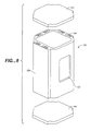
- FIG. 8 is a exploded perspective view of a load lock chamber according to the invention having peripheral tubular passages integral with the wall of the chamber where three side walls of the chamber containing fluid passages are of uniform thickness;
- FIG. 9 is a perspective view of a load lock chamber of the type shown in FIG. 5 having external tubular passages.
- FIG. 4 details the use of a generally square load lock chamber wall cross section 70 . It has an inside surface 72 which faces the inside space of the pressure vessel and has an outside surface 74 still contained within the radius of the extrusion limit 79 as shown by the dashed line 78 .
- the dashed line 78 shows the circle of the extrusion limit which in this instance is approximately 350 millimeters radius (700 millimeter diameter) to extrude the side wall assembly 70 shown.
- an O-ring groove 76 can be easily machined into the end once the piece is cut in lengths of approximately 24 to 30′′ to form load lock chambers.
- FIG. 5 shows an extruded load lock assembly 80 into a side of which is machined a transfer hole 82 and to which an extruded arrangement top plate 84 can be bolted.
- an extruded arrangement bottom plate 86 can be bolted to the bottom.
- the extruded arrangement top plate 84 includes piping nozzles (for example as shown by 88 ) for attaching gas and vacuum flow piping and tubing to the top of the chamber.
- a bottom plate includes nozzle openings (for example 90 ) in the bottom plate to connect to vacuum pumps and gas feed or evacuation devices.
- FIG. 6 shows an end of an extruded tube with integral cooling channels 100 wherein the inside wall 102 again faces an internal tubular space while the side wall top and bottom end surfaces include an O-ring groove 106 at its end inside a series of cooling tube openings in the integral wall of the chamber, for example as shown by 104 .
- the extrusion radius 79 and a limit of the extrusion circle 78 are consistent with that previously described for FIG. 4 above.
- FIG. 7 shows a prospective exploded view of a extruded thermally conditionable load lock assembly 110 .
- the side wall includes a substrate transfer opening 112 in one wall and a series of ribs 114 containing cooling passages.
- the ends of the cooling passages are connected by U-shaped piping connections, for example 116 both at the top and bottom with the end passages being connected to tubing and external pumps. While a serial path for the tubing connections is shown, the piping connections could configured to have a parallel, straight through, or multiple pass flow configuration.
- Thermal sensors inside the chamber can be matched to the thermal flow pattern in the passages in the sidewalls to achieve variations and/or uniformity as required for a particular process.
- a removable top seal plate 120 seals the top opening of the tubular sidewall structure, inside the piping connection 116 .
- a bottom removable seal plate 122 seals inside piping connections on the bottom.
- the top and bottom seal plates are bolted to the top and bottom through bolt holes not shown in this figure.
- FIG. 8 shows an alternate arrangement of a configuration according to the invention with an extruded thermally load lock assembly 130 having a substrate transfer opening 132 in a side wall.
- the thickened wall, e.g., 134 , of the three sides shown provides a larger thermal mass for heating and cooling of the contents of the chamber but also provides a larger area for extrusion which requires a greater force and some additional complexity in extruding the sidewall.
- a series of tubes similar in configuration to those shown in FIG. 7 exist in the side wall in the assembly as shown in FIG. 8 .
- Undercut grooves 140 are machined between adjacent grooves to replace the piping connections 116 shown in FIG. 7 . In this way a top plate 142 and a bottom plate 144 can be generally flat without requiring special machining or sealing to accommodate tubes around it and also eliminates the complication of installing and sealing numerous U-shaped separate tubing arrangements in the tubular side wall pieces.
- FIG. 9 shows an alternate embodiment of an extruded load lock sidewall with cooling passages 150 .
- the general shape of the sidewall configuration matches the shape of the extruded load lock shown in FIG. 5, and includes raised ribs containing cooling passages as discussed above.
Landscapes
- Engineering & Computer Science (AREA)
- Chemical & Material Sciences (AREA)
- Physics & Mathematics (AREA)
- Analytical Chemistry (AREA)
- Condensed Matter Physics & Semiconductors (AREA)
- Plasma & Fusion (AREA)
- Mechanical Engineering (AREA)
- General Physics & Mathematics (AREA)
- Manufacturing & Machinery (AREA)
- Computer Hardware Design (AREA)
- Microelectronics & Electronic Packaging (AREA)
- Power Engineering (AREA)
- Drying Of Semiconductors (AREA)
- Physical Vapour Deposition (AREA)
Abstract
A structure and method are present where a sidewall of a load lock chamber is formed by extrusion, to produce a reproducible tubular structure to form the walls of a vacuum chamber with greatly improved vacuum performance. The use of an extruded structure reduces the dimensional variability, increases the uniformity of a surface finish, and provides uniform top and bottom sealing arrangements, which allow full and easy access to the inside of the sidewalls for cleaning. In another arrangement heat transfer fluid passages can be formed in the wall of the chamber simultaneously as the wall of the chamber is extruded. Heating or cooling liquid can then be circulated through the passages in the wall of the chamber to heat the walls of the chamber as sometimes required to prevent condensation on the inside of the chamber walls, or provide cooling as is required for cool down of a wafer, after processing at an elevated temperature.
Description
This application is a divisional of application Ser. No. 09/151,187, filed Sep. 10, 1998, now U.S. Pat. No. 6,182,851, which is incorporated herein by reference, in its entirety, for all purposes.
This invention relates to the structure of the walls of a vacuum processing chamber and a method for producing vacuum processing chambers using extrusion technology to provide options and unexpected process improvements in processing semiconductor wafers.
In vacuum processing in general, and in processing of substrates on which electronic elements are being formed in particular, the speed with which vacuum pressure is achieved in a vacuum chamber is a critical path step in achieving specified vacuum process conditions so that substrates can be cycled and processed. Similarly, once stable substrate processing conditions are achieved, maintaining the integrity of the low pressure process requires that the process environment remain stable by minimizing pressure transients both short and long term which may cause or contribute to anomalies in process conditions.
The current state of the art is such that short fat substrate vacuum processing chambers are machined from a solid block of the base material. As a result, as much as 80% of the material is cut away before the final chamber configuration is arrived at. Similarly in cluster arrangements of processing chambers, the cluster tool housing is carved (machined) from a large block of the base material, again, much of it is wasted as it is cut away. The base material, usually a cast piece is specified to include a high degree of quality (material integrity) to assure that there are no openings through which gasses may leak into the chambers.
When tall narrow vacuum chambers are needed, the technique of machining material away from a block of base material is abandoned in favor of using large thick plates. Such plates are bent 90° to form an L-shaped cross section. An example of L-shaped cross section plates is shown in FIG. 1 (e.g., 22). Four of these L-shaped cross sections are welded together at their edges using butt welding techniques to form a tube which acts as the wall of the processing chamber. An example of the construction of this type of prior art arrangement is shown in FIG. 1. A set of four corner panels 22, 24, 26, and 28, having been bent into L-shaped pieces are complimented by a top plate 32 and a bottom plate 34. The location of a future substrate access opening is shown by dashed lines 30. The whole configuration of elements defines a process chamber assembly 20, which in this case is a relatively tall and thin load lock module as would be used associated with a cluster tool.
Once fixed elements of the process chamber assembly are joined by welding the configuration as seen in FIG. 2 is formed. The four corner panels 22, 24, 26, 28 having been welded together by four butt weld type joints whose weld region and heat affected zone are depicted by weld regions 52, 54, 56, and 58. Welding is done inside and out. Since the only performance criteria for the welds is pressure sealing, grinding and multipass welding is not uniformly performed, as is done in welds where the highest degree of quality assurance is required by specification. The bottom plate 34 is welded to the bottom of the tube formed by the welded plates. The weld region and heat affected zone of the bottom weld is represented by the lower weld area (heat affected zone) 60. Again the welding is done both inside and out, the inside weld being difficult to perform as it is being done at the bottom end extreme corner of a narrow closed end tube. Both the sidewall and bottom plate welds are minimally inspected and often contain inclusion, voids, and porosity.
Similarly the corners of the sidewall plates where they were bent contain, surface defects which are created or accentuated by the bending of the thick plate (for example—¾ inches (19.05 mm) thick).
As a result of the side and bottom plates being welded their final dimensions are uncertain, for example an O-ring groove 44 (shown in FIG. 3) in the end surface of the tube assembly, is intended to be centered in the end surface, with a particular configuration. Because the locations (dimensions) of the inside and outside surfaces vary slightly depending on how the welding was completed, before machining a rectangularly configured O-ring groove in the end surface of the tube, a machinist or machine tool must go through measuring steps to find a datum line between the inside and outside surfaces and then calculate where the machining should take place so that the O-ring groove when completed does not approach either an inner or an outer surface too closely.
An end view of the processing chamber of FIG. 2 is shown in FIG. 3. The locations of heat affected, weld zones are shown on each side (e.g., 42). The O-ring groove 44 is cut in the end surface to mate with the removable (top) cover plate.
A parameter specified in the material specification for a finished product is surface finish. Once all welding and machining is complete, a specified surface finish must be achieved on the surfaces of the plates both inside and out. Often the treatment of the surfaces to achieve a specified surface finish is a hand operation which is time consuming and variable. Inspection of such finishes is also subject to high rate of rejection for refinishing. It would be preferred to reduce the variability, improve uniformity, and reduce the time associated with achieving an acceptable surface finish.
Conventional vacuum chamber vacuum standards, find both machined and welded vacuum chamber structures acceptable when they are deemed tight, in that a vacuum pressure of 10−9 torr can be reached quickly and vacuum pressures of 10−5 to 10−8 torr can be maintained during processing. Improvements in vacuum performance are desired as a typical pumpdown time for a system is 20% (at the initial stage and further pump down required every time a wafer is being loaded and unloaded). A reduction in the pump down time can significantly affect product throughput.
A configuration and method according to the invention provides an unexpected improvement in vacuum chamber and vacuum processing within vacuum chambers in that the time to achieve a vacuum level of 10−9 torr is significantly reduced (approximately 15%) from that when using welded structures. Further, the use of an extrusion die provides a consistency and uniformity among all extrusions being drawn from the same die. Therefore, the time steps needed to perform datum measurements, necessary to effectively machine welded structures, are not necessary when extruded structures are used. Further, use of an extruded structure eliminates the volumetric porosity in the wall material, reduces surface cracking, provides a consistent surface finish, and eliminates undesirable inclusions that readily appear when large plates are bent and then welded. Because of the high degree of material integrity in the wall of the chamber and the elimination of side wall welds and complications associated with machining through such welds, both the bottom and top edges of the extruded tube can be machined for O-ring grooves to receive top and bottom sealing plates which can be bolted to the top and bottom of the extruded tube. Such bolting eliminates the need for special treatment and/or quality control when using a welded joint and also reduces the complications associated with constructing and using a pressure vessel having an end which has been welded shut. Those complications include the requirement that a portion of the well be done deep inside a tube at its end. In the prior art structure, is hard to check the integrity of such a weld. Cleaning of a vacuum chamber constructed with a closed end (as in the prior art) requires careful attention to cleaning of the extreme bottom end and the corner between the end cap and the side wall to be sure that all deleterious substances are removed. In contrast, a structure according to present invention allows the end caps to be removed to access the inside of the side walls easily from both ends which thereby eliminates corners once the top and bottom plates are removed. In this configuration the side walls can be cleaned directly and the top and bottom plates can be cleaned directly as well.
In an extruded configuration according to the present invention, it is possible to extrude a pressure vessel side wall while including voids or tubes in the side wall separated from the pressure vessel space. In such an arrangement, cooling or heating liquid can be circulated through the separate tubes to directly heat or cool the side of the pressure vessel. Such an arrangement/configuration provides greatly increased efficiency in terms of the production of a heated or cooled pressure vessel by eliminating the step of having to attach by welding, brazing or other methods, a set of cooling type coils or pipes carrying a thermal transfer liquid to the outside of a pressure vessel. Secondly, the integration of the cooling channels enhances the transfer of thermal energy between the liquid flowing through the cooling/hearing channels and the material of the side well, as compared to the small weld or brazing area that is utilized when external tubing or piping is welded or brazed to the outside of a pressure vessel. Any imperfect connection between such tubing and a pressure vessel would cause differential thermal expansion which may create gaps that further reduce the thermal conductivity between the fluid flowing and the cooling channels in the side wall of the chamber.
In a preferred configuration, linear tubing passages are configured within the wall of the chamber. The ends of the heat transfer tubes in the walls of the chamber are connected by a series of connecting conduits between individual passages of the series of preferably tubular passages. Or, the ends of conduits in the wall can be undercut to provide a passage between adjacent tubes at the top and bottom of the extruded sidewall ends so that a flat plate covering the tube and passages will seal the fluid passage between adjacent individual passages.
A 15% improvement in pumpdown time translates into a 3% overall improvement in substrate (wafer) throughput. A leak rate improvement of three to five times can translate into a 3 to 5% faster throughput cycle. Since a 0.25% throughput improvement is considered “significant” in the substrate processing industry, a 3 to 5% improvement is not only significant, but substantial.
A method according to the invention includes the steps of extruding a tube to be used as pressure vessel; machining its ends surfaces to receive O-rings and machining its side surfaces to accommodate transfer mechanisms and doors as needed for processing operations.
FIG. 1 is a perspective exploded view of L-shaped sidewall pieces of a prior art load lock chamber prior to their being welded and assembled;
FIG. 2 is a perspective view of a welded up prior art load lock chamber the construction elements of which are shown in FIG. 1;
FIG. 3 is an end view of the load lock chamber of FIG. 2;
FIG. 4 is an end view of a load lock chamber in a configuration according to the invention;
FIG. 5 is an exploded perspective view of a load lock chamber configured in accordance with the invention;
FIG. 6 is an end view of a load lock chamber extrusion with integral tubular passages end outside its wall separate from the center space of the vessel;
FIG. 7 is an exploded perspective view of a load lock chamber according to the invention having external tubular passages for heating and cooling of the type as show in FIG. 6 where those heating and external tubular passages are configured in a series flow pattern by a set of tubular or piping members;
FIG. 8 is a exploded perspective view of a load lock chamber according to the invention having peripheral tubular passages integral with the wall of the chamber where three side walls of the chamber containing fluid passages are of uniform thickness; and
FIG. 9 is a perspective view of a load lock chamber of the type shown in FIG. 5 having external tubular passages.
Extrusions of small items in the range of ¼ to 6″ in diameter or across is commonly seen in many kinds of industrial parts. Extrusions for a large piece as presented herein, up to 24 or 27″ in diameter, for use as a pressure vessel is previously unknown. FIG. 4 details the use of a generally square load lock chamber wall cross section 70. It has an inside surface 72 which faces the inside space of the pressure vessel and has an outside surface 74 still contained within the radius of the extrusion limit 79 as shown by the dashed line 78. The dashed line 78 shows the circle of the extrusion limit which in this instance is approximately 350 millimeters radius (700 millimeter diameter) to extrude the side wall assembly 70 shown. Once extruded, an O-ring groove 76 can be easily machined into the end once the piece is cut in lengths of approximately 24 to 30″ to form load lock chambers.
FIG. 5 shows an extruded load lock assembly 80 into a side of which is machined a transfer hole 82 and to which an extruded arrangement top plate 84 can be bolted. Similarly, an extruded arrangement bottom plate 86 can be bolted to the bottom. The extruded arrangement top plate 84 includes piping nozzles (for example as shown by 88) for attaching gas and vacuum flow piping and tubing to the top of the chamber. Similarly, a bottom plate includes nozzle openings (for example 90) in the bottom plate to connect to vacuum pumps and gas feed or evacuation devices.
FIG. 6 shows an end of an extruded tube with integral cooling channels 100 wherein the inside wall 102 again faces an internal tubular space while the side wall top and bottom end surfaces include an O-ring groove 106 at its end inside a series of cooling tube openings in the integral wall of the chamber, for example as shown by 104. The extrusion radius 79 and a limit of the extrusion circle 78 are consistent with that previously described for FIG. 4 above.
FIG. 7 shows a prospective exploded view of a extruded thermally conditionable load lock assembly 110. The side wall includes a substrate transfer opening 112 in one wall and a series of ribs 114 containing cooling passages. The ends of the cooling passages are connected by U-shaped piping connections, for example 116 both at the top and bottom with the end passages being connected to tubing and external pumps. While a serial path for the tubing connections is shown, the piping connections could configured to have a parallel, straight through, or multiple pass flow configuration. Thermal sensors inside the chamber can be matched to the thermal flow pattern in the passages in the sidewalls to achieve variations and/or uniformity as required for a particular process. A removable top seal plate 120 seals the top opening of the tubular sidewall structure, inside the piping connection 116. Similarly a bottom removable seal plate 122 seals inside piping connections on the bottom. The top and bottom seal plates are bolted to the top and bottom through bolt holes not shown in this figure.
FIG. 8 shows an alternate arrangement of a configuration according to the invention with an extruded thermally load lock assembly 130 having a substrate transfer opening 132 in a side wall. The thickened wall, e.g., 134, of the three sides shown provides a larger thermal mass for heating and cooling of the contents of the chamber but also provides a larger area for extrusion which requires a greater force and some additional complexity in extruding the sidewall. A series of tubes similar in configuration to those shown in FIG. 7 exist in the side wall in the assembly as shown in FIG. 8. Undercut grooves 140 are machined between adjacent grooves to replace the piping connections 116 shown in FIG. 7. In this way a top plate 142 and a bottom plate 144 can be generally flat without requiring special machining or sealing to accommodate tubes around it and also eliminates the complication of installing and sealing numerous U-shaped separate tubing arrangements in the tubular side wall pieces.
FIG. 9 shows an alternate embodiment of an extruded load lock sidewall with cooling passages 150. The general shape of the sidewall configuration matches the shape of the extruded load lock shown in FIG. 5, and includes raised ribs containing cooling passages as discussed above.
The benefits of improved material quality , ease of manufacture, uniformity of dimension, and improved surface finish uniformity along with the completely unexpected result of a quantum improvement in vacuum performance provide advantages not known or expected from the prior art.
While the invention has been described with regards to specific embodiments, those scaled in the art will recognize that changes can be made in form or detail without departing from the spirit and scope of the intention.
Claims (14)
1. A method of producing a vacuum containment vessel comprising the steps of:
extruding a tubular body element, the tubular body element encircling a central space, said tubular body element having a body side and a first open end and a second open end;
providing sealable openings in the side of the tubular body element;
attaching a first end closure to seal said first end of said tubular body element and attaching a second end closure to seal said second end of said tubular body element.
2. The method of producing a vacuum containment vessel as in claim 1 ,
wherein said tubular body element includes a series of tubular passages in the wall of said body element separated from said central space by a portion of said body element.
3. The method of producing a vacuum containment vessel as in claim 2 , further comprising the step of:
providing fluid communication between at least two tubular passages of said series of tubular passages in the wall of said body element.
4. The method of producing a vacuum containment vessel as in claim 3 ,
wherein said step of providing fluid communication includes providing grooved passages in the end surfaces of the tubular body element, such that when sealed by a cover said end closures, thermal transfer fluid flowing from a first of said tubular passages in the wall of said body element passes through one of said grooved passages in the end of an tubular body element and into a second of said tubular passages in the wall of said body element.
5. A method of producing a vacuum containment vessel, the method comprising:
extruding a tubular body element, the tubular body element encircling a central space, the tubular body element having a body side and a first open end and a second open end;
providing a sealable opening in the body side of the tubular body element;
attaching a first end closure to seal the first open end of the tubular body element; and
attaching a second end closure to seal the second open end of the tubular body element.
6. The method of producing a vacuum containment vessel as in claim 5 , wherein the tubular body element includes a series of tubular passages therein, the series of tubular passages being separated from said central space by a portion of the tubular body element.
7. The method of producing a vacuum containment vessel as in claim 6 , further comprising:
providing fluid communication between at least two tubular passages of the series of tubular passages.
8. The method of producing a vacuum containment vessel as in claim 7 , wherein providing fluid communication includes providing grooved passages in an end surface of the tubular body element, such that when sealed by one of such said end closures, thermal transfer fluid flowing from a first of said tubular passages in the wall of said body element passes through one of the grooved passages in the end of the tubular body element and into a second of the tubular passages.
9. A method of manufacturing an article for use in processing a semiconductor wafer, the method comprising:
extruding a tubular element, the tubular element encircling a central space, the tubular element having a side and open ends;
forming an opening in the side of the tubular element, the opening being sized so as to permit the semiconductor wafer to be processed to be transferred into and out of the central space.
10. The method of manufacturing an article of claim 9 , the method further comprising:
attaching an end closure to an open end of the tubular element.
11. The method of manufacturing an article of claim 9 , wherein the tubular element is extruded so that the tubular element includes a series of peripheral tubular passages integral therewith and separated from the central space by a portion of the tubular element, the series of peripheral tubular passages being isolated from the central space.
12. The method of manufacturing an article of claim 9 , wherein the tubular element is extruded so as to provide a series of ribs integral therewith for containing peripheral tubular passages separated from the central space by a portion of the tubular element, the series of peripheral tubular passages being isolated from the central space.
13. A method of manufacturing an article for use in processing a semiconductor wafer, the method comprising:
extruding a tubular element, wherein the tubular element encircles a central space, wherein the tubular element has a side and open ends, and wherein the tubular element is extruded so that the tubular element includes a series of peripheral tubular passages integral therewith and separated from the central space by a portion of the tubular element, the series of peripheral tubular passages being isolated from the central space; and
providing fluid connection between the series of peripheral tubular passages.
14. The method of manufacturing an article of claim 13 , the method further comprising:
forming an opening in the side of the tubular element, the opening being sized so as to permit the semiconductor wafer to be processed to be transferred into and out of the central space.
Priority Applications (1)
| Application Number | Priority Date | Filing Date | Title |
|---|---|---|---|
| US09/711,192 US6405423B1 (en) | 1998-09-10 | 2000-11-13 | Method for producing vacuum processing chambers |
Applications Claiming Priority (2)
| Application Number | Priority Date | Filing Date | Title |
|---|---|---|---|
| US09/151,187 US6182851B1 (en) | 1998-09-10 | 1998-09-10 | Vacuum processing chambers and method for producing |
| US09/711,192 US6405423B1 (en) | 1998-09-10 | 2000-11-13 | Method for producing vacuum processing chambers |
Related Parent Applications (1)
| Application Number | Title | Priority Date | Filing Date |
|---|---|---|---|
| US09/151,187 Division US6182851B1 (en) | 1998-09-10 | 1998-09-10 | Vacuum processing chambers and method for producing |
Publications (1)
| Publication Number | Publication Date |
|---|---|
| US6405423B1 true US6405423B1 (en) | 2002-06-18 |
Family
ID=22537681
Family Applications (2)
| Application Number | Title | Priority Date | Filing Date |
|---|---|---|---|
| US09/151,187 Expired - Fee Related US6182851B1 (en) | 1998-09-10 | 1998-09-10 | Vacuum processing chambers and method for producing |
| US09/711,192 Expired - Fee Related US6405423B1 (en) | 1998-09-10 | 2000-11-13 | Method for producing vacuum processing chambers |
Family Applications Before (1)
| Application Number | Title | Priority Date | Filing Date |
|---|---|---|---|
| US09/151,187 Expired - Fee Related US6182851B1 (en) | 1998-09-10 | 1998-09-10 | Vacuum processing chambers and method for producing |
Country Status (1)
| Country | Link |
|---|---|
| US (2) | US6182851B1 (en) |
Cited By (11)
| Publication number | Priority date | Publication date | Assignee | Title |
|---|---|---|---|---|
| US20040240983A1 (en) * | 2003-06-02 | 2004-12-02 | Jusung Engineering Co., Ltd. | Transfer chamber for cluster system |
| US20050285992A1 (en) * | 2004-06-02 | 2005-12-29 | Applied Materials, Inc. | Methods and apparatus for sealing a chamber |
| US20060028596A1 (en) * | 2004-06-02 | 2006-02-09 | Leung Billy C | Methods and apparatus for providing a floating seal for chamber doors |
| US20070166133A1 (en) * | 2006-01-13 | 2007-07-19 | Applied Materials, Inc. | Decoupled chamber body |
| US20080110760A1 (en) * | 2002-01-08 | 2008-05-15 | Applied Materials, Inc. | Process chamber component having yttrium-aluminum coating |
| US20100043648A1 (en) * | 2006-01-30 | 2010-02-25 | Lichtenstein David M | Pastry Shell Baking Rings |
| US20100181500A1 (en) * | 2009-01-16 | 2010-07-22 | Taiwan Semiconductor Manufacturing Co., Ltd. | Method and system for low temperature ion implantation |
| US20140250658A1 (en) * | 2013-03-05 | 2014-09-11 | Applied Materials, Inc. | Vacuum chambers and components for semiconductor substrate processing and methods of fabrication |
| US20160010897A1 (en) * | 2008-08-29 | 2016-01-14 | Werner Extrusion Solutions, Llc | Node, Apparatus, System and Method Regarding a Frame Support for Solar Mirrors |
| WO2016008844A1 (en) | 2014-07-17 | 2016-01-21 | Christof-Herbert Diener | Vacuum system, in particular a plasma system, having a completely enclosed chamber extruded profile |
| USD836212S1 (en) * | 2015-08-14 | 2018-12-18 | Christof-Herbert Diener | Vacuum device |
Families Citing this family (9)
| Publication number | Priority date | Publication date | Assignee | Title |
|---|---|---|---|---|
| JP4158386B2 (en) * | 2002-02-28 | 2008-10-01 | 東京エレクトロン株式会社 | Cooling apparatus and heat treatment apparatus using the same |
| US20050199632A1 (en) * | 2004-03-12 | 2005-09-15 | Anderson Albin L. | Bag keeper system, and components therefor |
| CN103199039B (en) * | 2004-06-02 | 2016-01-13 | 应用材料公司 | Electron device manufacturing chamber and forming method thereof |
| US20070116873A1 (en) * | 2005-11-18 | 2007-05-24 | Tokyo Electron Limited | Apparatus for thermal and plasma enhanced vapor deposition and method of operating |
| JP4784599B2 (en) * | 2007-12-28 | 2011-10-05 | 東京エレクトロン株式会社 | Vacuum processing apparatus, vacuum processing method, and storage medium |
| KR20100000146A (en) * | 2008-06-24 | 2010-01-06 | 주성엔지니어링(주) | Vacuum chamber for treatmenting substrate including chamber lid |
| US20100116823A1 (en) * | 2008-11-07 | 2010-05-13 | Applied Materials, Inc. | Hydroformed fluid channels |
| DE102010008084A1 (en) * | 2010-02-15 | 2011-08-18 | Leybold Optics GmbH, 63755 | Device for thermal treatment of substrates |
| EP3564538B1 (en) * | 2019-02-20 | 2021-04-07 | Pfeiffer Vacuum Gmbh | Vacuum system and method for manufacturing the same |
Citations (13)
| Publication number | Priority date | Publication date | Assignee | Title |
|---|---|---|---|---|
| US2071728A (en) | 1934-07-31 | 1937-02-23 | Bursitzky Hans | Apparatus for utilizing blocks of carbon dioxide ice |
| US2940734A (en) | 1957-12-16 | 1960-06-14 | Babcock & Wilcox Co | Banded pressure vessels |
| US3515302A (en) | 1968-03-14 | 1970-06-02 | Frank J Curran Co | Package for solid diffusing material |
| US3817371A (en) | 1972-01-31 | 1974-06-18 | Pure Co Inc | Container |
| US4027379A (en) | 1973-06-15 | 1977-06-07 | The Dow Chemical Company | Method of insulating cryogenic vessels |
| US4340462A (en) | 1981-02-13 | 1982-07-20 | Lam Research Corporation | Adjustable electrode plasma processing chamber |
| US4932546A (en) * | 1989-03-16 | 1990-06-12 | Buttes Gas & Oil Co. | Pressure vessel |
| US5564587A (en) | 1991-12-23 | 1996-10-15 | Falk; Ingemar | Pressure container |
| US5746434A (en) | 1996-07-09 | 1998-05-05 | Lam Research Corporation | Chamber interfacing O-rings and method for implementing same |
| US5820723A (en) | 1996-06-05 | 1998-10-13 | Lam Research Corporation | Universal vacuum chamber including equipment modules such as a plasma generating source, vacuum pumping arrangement and/or cantilevered substrate support |
| US5983829A (en) | 1995-11-01 | 1999-11-16 | Canon Kabushiki Kaisha | Microwave plasma etching apparatus |
| US6039080A (en) * | 1995-09-29 | 2000-03-21 | Stork R.M.S. B.V. | Machine frame for the meat processing industry and tube profile |
| US6290085B1 (en) * | 1997-08-28 | 2001-09-18 | Showa Denko K.K. | Partitioned closed container, its production method and pressure container |
-
1998
- 1998-09-10 US US09/151,187 patent/US6182851B1/en not_active Expired - Fee Related
-
2000
- 2000-11-13 US US09/711,192 patent/US6405423B1/en not_active Expired - Fee Related
Patent Citations (14)
| Publication number | Priority date | Publication date | Assignee | Title |
|---|---|---|---|---|
| US2071728A (en) | 1934-07-31 | 1937-02-23 | Bursitzky Hans | Apparatus for utilizing blocks of carbon dioxide ice |
| US2940734A (en) | 1957-12-16 | 1960-06-14 | Babcock & Wilcox Co | Banded pressure vessels |
| US3515302A (en) | 1968-03-14 | 1970-06-02 | Frank J Curran Co | Package for solid diffusing material |
| US3817371A (en) | 1972-01-31 | 1974-06-18 | Pure Co Inc | Container |
| US4027379A (en) | 1973-06-15 | 1977-06-07 | The Dow Chemical Company | Method of insulating cryogenic vessels |
| US4340462A (en) | 1981-02-13 | 1982-07-20 | Lam Research Corporation | Adjustable electrode plasma processing chamber |
| US4932546A (en) * | 1989-03-16 | 1990-06-12 | Buttes Gas & Oil Co. | Pressure vessel |
| US5564587A (en) | 1991-12-23 | 1996-10-15 | Falk; Ingemar | Pressure container |
| US6039080A (en) * | 1995-09-29 | 2000-03-21 | Stork R.M.S. B.V. | Machine frame for the meat processing industry and tube profile |
| US5983829A (en) | 1995-11-01 | 1999-11-16 | Canon Kabushiki Kaisha | Microwave plasma etching apparatus |
| US5820723A (en) | 1996-06-05 | 1998-10-13 | Lam Research Corporation | Universal vacuum chamber including equipment modules such as a plasma generating source, vacuum pumping arrangement and/or cantilevered substrate support |
| US5746434A (en) | 1996-07-09 | 1998-05-05 | Lam Research Corporation | Chamber interfacing O-rings and method for implementing same |
| US6010133A (en) | 1996-07-09 | 2000-01-04 | Lam Research Corporation | Chamber interfacing O-rings and method for implementing same |
| US6290085B1 (en) * | 1997-08-28 | 2001-09-18 | Showa Denko K.K. | Partitioned closed container, its production method and pressure container |
Cited By (29)
| Publication number | Priority date | Publication date | Assignee | Title |
|---|---|---|---|---|
| US8114525B2 (en) | 2002-01-08 | 2012-02-14 | Applied Materials, Inc. | Process chamber component having electroplated yttrium containing coating |
| US9012030B2 (en) | 2002-01-08 | 2015-04-21 | Applied Materials, Inc. | Process chamber component having yttrium—aluminum coating |
| US8110086B2 (en) * | 2002-01-08 | 2012-02-07 | Applied Materials, Inc. | Method of manufacturing a process chamber component having yttrium-aluminum coating |
| US20080110760A1 (en) * | 2002-01-08 | 2008-05-15 | Applied Materials, Inc. | Process chamber component having yttrium-aluminum coating |
| US20080223725A1 (en) * | 2002-01-08 | 2008-09-18 | Applied Materials, Inc. | Process chamber component having electroplated yttrium containing coating |
| US20040240983A1 (en) * | 2003-06-02 | 2004-12-02 | Jusung Engineering Co., Ltd. | Transfer chamber for cluster system |
| US20050205012A1 (en) * | 2003-06-02 | 2005-09-22 | Jusung Engineering Co., Ltd. | Transfer chamber for cluster system |
| US7282460B2 (en) * | 2003-06-02 | 2007-10-16 | Jusung Engineering Co., Ltd. | Transfer chamber for cluster system |
| US20080029029A1 (en) * | 2003-06-02 | 2008-02-07 | Jusung Engineering Co., Ltd. | Transfer chamber for cluster system |
| US7375041B2 (en) * | 2003-06-02 | 2008-05-20 | Jusung Engineering Co., Ltd. | Transfer chamber for cluster system |
| US8206075B2 (en) * | 2004-06-02 | 2012-06-26 | Applied Materials, Inc. | Methods and apparatus for sealing a chamber |
| US8648977B2 (en) | 2004-06-02 | 2014-02-11 | Applied Materials, Inc. | Methods and apparatus for providing a floating seal having an isolated sealing surface for chamber doors |
| US9580956B2 (en) | 2004-06-02 | 2017-02-28 | Applied Materials, Inc. | Methods and apparatus for providing a floating seal for chamber doors |
| US20060028596A1 (en) * | 2004-06-02 | 2006-02-09 | Leung Billy C | Methods and apparatus for providing a floating seal for chamber doors |
| US20050285992A1 (en) * | 2004-06-02 | 2005-12-29 | Applied Materials, Inc. | Methods and apparatus for sealing a chamber |
| US20070166133A1 (en) * | 2006-01-13 | 2007-07-19 | Applied Materials, Inc. | Decoupled chamber body |
| US7845891B2 (en) * | 2006-01-13 | 2010-12-07 | Applied Materials, Inc. | Decoupled chamber body |
| US20100043648A1 (en) * | 2006-01-30 | 2010-02-25 | Lichtenstein David M | Pastry Shell Baking Rings |
| US20160010897A1 (en) * | 2008-08-29 | 2016-01-14 | Werner Extrusion Solutions, Llc | Node, Apparatus, System and Method Regarding a Frame Support for Solar Mirrors |
| US10240819B2 (en) * | 2008-08-29 | 2019-03-26 | Werner Extrusion Solutions LLC | Node, apparatus, system and method regarding a frame support for solar mirrors |
| US20100181500A1 (en) * | 2009-01-16 | 2010-07-22 | Taiwan Semiconductor Manufacturing Co., Ltd. | Method and system for low temperature ion implantation |
| US20140250658A1 (en) * | 2013-03-05 | 2014-09-11 | Applied Materials, Inc. | Vacuum chambers and components for semiconductor substrate processing and methods of fabrication |
| DE102014213942B4 (en) * | 2014-07-17 | 2016-01-28 | Christof-Herbert Diener | Vacuum system, in particular plasma system, with a completely closed chamber extruded profile |
| DE102014213942A1 (en) | 2014-07-17 | 2016-01-21 | Christof-Herbert Diener | Vacuum system, in particular plasma system, with a completely closed chamber extruded profile |
| CN106537551A (en) * | 2014-07-17 | 2017-03-22 | 克里斯托夫-赫伯特·迪纳 | Vacuum system, in particular a plasma system, having a completely enclosed chamber extruded profile |
| CN106537551B (en) * | 2014-07-17 | 2018-05-08 | 克里斯托夫-赫伯特·迪纳 | The vacuum equipment of chamber extrudate with all round closure |
| US10041730B2 (en) | 2014-07-17 | 2018-08-07 | Christof-Herbert Diener | Plasma vacuum system having a completely enclosed chamber extruded profile |
| WO2016008844A1 (en) | 2014-07-17 | 2016-01-21 | Christof-Herbert Diener | Vacuum system, in particular a plasma system, having a completely enclosed chamber extruded profile |
| USD836212S1 (en) * | 2015-08-14 | 2018-12-18 | Christof-Herbert Diener | Vacuum device |
Also Published As
| Publication number | Publication date |
|---|---|
| US6182851B1 (en) | 2001-02-06 |
Similar Documents
| Publication | Publication Date | Title |
|---|---|---|
| US6405423B1 (en) | Method for producing vacuum processing chambers | |
| US5429183A (en) | Plate-type heat exchanger and method of producing the same | |
| US20150030766A1 (en) | Pedestal bottom clean for improved fluorine utilization and integrated symmetric foreline | |
| RU2268387C2 (en) | Method of manufacturing combustion chamber | |
| US20170157723A1 (en) | Method for production of a heat exchanger with at least two fluid circulation circuits with a large number of channels and/or large dimensions | |
| US7575616B2 (en) | Low-profile surface mount filter | |
| JPH07176601A (en) | Quasi-infinite heat source/heat sink | |
| US6216328B1 (en) | Transport chamber and method for making same | |
| WO2002093605A2 (en) | Cylinder-based plasma processing system | |
| US20030172657A1 (en) | Fluid temperature control apparatus | |
| CN215481420U (en) | Air inlet spraying assembly and air inlet spraying equipment | |
| US20220282377A1 (en) | Thermally controlled chandelier showerhead | |
| US20060162656A1 (en) | Reduced volume, high conductance process chamber | |
| TWI233377B (en) | Continuous coating apparatus | |
| US5996390A (en) | Method for manufacturing vacuum chamber | |
| CN110323038B (en) | Aluminum alloy radiator for oil immersed power transformer and manufacturing method | |
| US4740981A (en) | Temperature controller for gas laser resonator | |
| US6953143B2 (en) | Explosion welded design for cooling components | |
| US20060086475A1 (en) | Aluminium composite structure having a channel therein and method of manufacturing the same | |
| CN113290198A (en) | Method for preparing hollow integral structure by using pipe | |
| CN221192318U (en) | Semiconductor cavity | |
| JP2000095199A (en) | Temperature controlled base plate | |
| WO2020195820A1 (en) | Substrate-processing device and production method for substrate-processing device | |
| US12011764B1 (en) | Metal 3D printed heat exchangers and fluid directing devices | |
| CN220691995U (en) | Wafer carrying mechanism and wafer processing system |
Legal Events
| Date | Code | Title | Description |
|---|---|---|---|
| FPAY | Fee payment |
Year of fee payment: 4 |
|
| REMI | Maintenance fee reminder mailed | ||
| LAPS | Lapse for failure to pay maintenance fees | ||
| STCH | Information on status: patent discontinuation |
Free format text: PATENT EXPIRED DUE TO NONPAYMENT OF MAINTENANCE FEES UNDER 37 CFR 1.362 |