US6381122B2 - Bus bar system with several bus bars and an installation device with flat connectors - Google Patents

Bus bar system with several bus bars and an installation device with flat connectors Download PDF

Info

Publication number
US6381122B2
US6381122B2 US09/761,099 US76109901A US6381122B2 US 6381122 B2 US6381122 B2 US 6381122B2 US 76109901 A US76109901 A US 76109901A US 6381122 B2 US6381122 B2 US 6381122B2
Authority
US
United States
Prior art keywords
bus bar
bar system
accordance
installation device
bus bars
Prior art date
Legal status (The legal status is an assumption and is not a legal conclusion. Google has not performed a legal analysis and makes no representation as to the accuracy of the status listed.)
Expired - Fee Related
Application number
US09/761,099
Other versions
US20010028547A1 (en
Inventor
Hans Wagener
Current Assignee (The listed assignees may be inaccurate. Google has not performed a legal analysis and makes no representation or warranty as to the accuracy of the list.)
Rittal Werk Rudolf Loh GmbH and Co KG
Original Assignee
Rittal Werk Rudolf Loh GmbH and Co KG
Priority date (The priority date is an assumption and is not a legal conclusion. Google has not performed a legal analysis and makes no representation as to the accuracy of the date listed.)
Filing date
Publication date
Application filed by Rittal Werk Rudolf Loh GmbH and Co KG filed Critical Rittal Werk Rudolf Loh GmbH and Co KG
Assigned to RITTAL RUDOLF LOH GMBH & CO. KG reassignment RITTAL RUDOLF LOH GMBH & CO. KG ASSIGNMENT OF ASSIGNORS INTEREST (SEE DOCUMENT FOR DETAILS). Assignors: WAGENER, HANS
Publication of US20010028547A1 publication Critical patent/US20010028547A1/en
Application granted granted Critical
Publication of US6381122B2 publication Critical patent/US6381122B2/en
Anticipated expiration legal-status Critical
Expired - Fee Related legal-status Critical Current

Links

Images

Classifications

    • HELECTRICITY
    • H02GENERATION; CONVERSION OR DISTRIBUTION OF ELECTRIC POWER
    • H02GINSTALLATION OF ELECTRIC CABLES OR LINES, OR OF COMBINED OPTICAL AND ELECTRIC CABLES OR LINES
    • H02G5/00Installations of bus-bars
    • H02G5/02Open installations
    • H02G5/025Supporting structures
    • HELECTRICITY
    • H02GENERATION; CONVERSION OR DISTRIBUTION OF ELECTRIC POWER
    • H02BBOARDS, SUBSTATIONS OR SWITCHING ARRANGEMENTS FOR THE SUPPLY OR DISTRIBUTION OF ELECTRIC POWER
    • H02B1/00Frameworks, boards, panels, desks, casings; Details of substations or switching arrangements
    • H02B1/20Bus-bar or other wiring layouts, e.g. in cubicles, in switchyards

Abstract

A bus bar system having several bus bars spaced apart from each other in a first connecting plane and of an essentially square cross section and having T-shaped connecting grooves cut into all outsides for a connection with electrical installation devices having flat connectors in a second connecting plane, which is arranged perpendicular to the first connecting plane. With specially embodied connecting and insulating elements, it is possible to displace the connecting planes of the bus bars and of the flat connectors of the installations device parallel and perpendicular with respect to each other without it being necessary to perform elaborate matching assembly work at the site.

Description

BACKGROUND OF THE INVENTION
1. Field of the Invention
This invention relates to a bus bar system having several bus bars, which are spaced apart from each other in a first connecting plane, are of an essentially square cross section and have T-shaped connecting grooves cut into all outsides for a connection with electrical installation devices having flat connectors in a second connecting plane, which is arranged perpendicularly to the first connecting plane.
2. Description of Related Art
Bus bars and electrical installation devices of this type are preferably used for high current strength and are designed with appropriate large cross sections in current-carrying areas. If, for example, the bus bars are arranged in a horizontal connecting plane of a switchgear cabinet, and if the installation device to be connected which has flat connectors located in one plane is to be installed in the switchgear cabinet in a vertical connecting plane, it is necessary to use specially angled and/or bent off connecting contacts between the bus bars and the flat connectors, because the respective connecting points for the individual bus bars and the associated flat connectors are spatially arranged differently from each other. Thus the connecting contacts can only be made after the installation location of the installation device is set. However, this presents considerable difficulties at the place of employment of the switchgear cabinet, particularly if the connecting contacts are formed as flat rails for great current strengths.
SUMMARY OF THE INVENTION
It is one object of this invention to provide a bus bar system of the type mentioned above but wherein a connection between the bus bars and the flat connectors of an installation device is made with prefabricated parts, even if the bus bars are arranged in two connecting planes which extend perpendicularly with respect to each other.
In accordance with this invention, this object is achieved with insulating bows, or insulating chassis, which can be fastened on the side of the bus bars facing the installation device at the spacing of the flat connectors of the installation device, which extend perpendicular to a linear direction of the bus bars and can have a cutout in the area of each bus bar. A contact piece, which can be connected with the associated bus bar, can be inserted into each insulating chassis only in the area of an associated bus bar. The insulating chassis receives a connecting leg of connecting elbows, which can be or are connected together with the associated contact piece and with the associated bus bar. Together with a connecting leg projecting from the insulating chassis, the connecting contacts form connecting points for the flat connectors of the installation device in the second fastening plane, which extends perpendicularly with respect to the first fastening plane.
Connecting points to the individual bus bars can be established by the insulation chassis, the contact pieces and the connecting elbows, with a plane that is aligned with the connecting plane of the flat connectors of the installation device, for example, that extends parallel with the installation device. The insulation chassis, the contact pieces and the connecting bows can be prefabricated and provided as kits for defined maximum current strengths.
Fastening of the contact pieces and of the connecting elbows with the insulating bows to the bus bars is accomplished in accordance with one embodiment because the connecting grooves of the bus bar receive sliding nuts with threaded receivers, into which connecting screws can be screwed which can be or are inserted through fastening bores of the connecting elbows and the contact pieces.
In this embodiment, the lateral legs of the insulating chassis form a receiver for the connecting legs of the connecting elbows, which extends transversely to the linear direction of the bus bars.
So that uniform connecting elbows can be used, in a further embodiment the connecting legs of the connecting elbows have a row of fastening bores, at least one fastening bore of which is arranged in the area of the cutouts assigned to the bus bars. Therefore the spatial orientation of the insulating bows and the connecting elbows received in them in the first connecting plane of the bus bars remains the same, but it is assured that the connections with the associated bus bars can be individually made because appropriate cutouts in the insulating bows are occupied by contact pieces.
The connection of the installation device is simplified because the end areas of the junction legs of the connecting elbows have connecting bores, which are matched to the fastening bores in the flat connectors of the installation device.
In a further embodiment, the cutouts in the insulating bows can be provided as needed by partial areas which can be broken out and thus it is possible to create the cutout for the contact piece only at the desired location. Then access to bus bars, which are not to be connected, is prevented thus improving insulation toward the connecting elbow, which is not involved.
In a further adaptation option for the two connecting planes the junction legs of the connecting elbows can be extended by flat rails for increasing a distance between the contact places for the installation device perpendicularly with respect to the first connecting plane of the bus bars. The flat rails can be or are connected with the flat connectors of the installation device using Z-shaped transition pieces.
In one embodiment, the connecting elbows are assembled from several individual connecting elbows, having connecting legs that rest on top of each other and junction legs spaced apart from each other. A space between the junction legs is matched to the thickness of the flat connectors of the installation device. Unoccupied spaces are filled with spacing contact pieces. The flat rails and the transition pieces are put together from several spaced apart individual flat rails and individual transition pieces, wherein their spacing is matched to the thickness of the junction legs of the connecting bows and of the flat connectors of the installation device. These individual elements can be used for maximum current strengths of arbitrary size when one or several of these individual elements are combined to form a connecting elbow, a flat rail and a Z-shaped transition piece.
The individual elements can be maintained at a distance from each other using special spacing elements.
Contacts between the bus bar and the contact piece can be improved because the contact pieces are designed in a bow shape and form a receiver for the bus bar with their lateral legs.
BRIEF DESCRIPTION OF THE DRAWINGS
This invention is explained in greater detail in view of exemplary embodiments shown in the drawings, wherein:
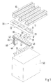
FIG. 1 is an exploded perspective view of a bus bar system with three bus bars in a horizontal connecting plane and an electrical installation device having flat connectors arranged in a vertical connecting plane;
FIG. 2 is an exploded perspective view of a portion of a bus bar having a sliding nut, which can be inserted into a connecting groove;
FIG. 3 is an exploded perspective view of a bus bar system corresponding to FIG. 1, wherein the vertical connecting plane for the flat connectors of the installation device can be displaced perpendicularly and parallel with respect to the horizontal connecting plane of the bus bar using flat rails and Z-shaped transition pieces; and
FIG. 4 is an exploded perspective view of a bus bar system wherein differently designed connecting rails, on which the installation devices can be pushed by means of spring contacts, can be attached to the connecting elbows.
DESCRIPTION OF PREFERRED EMBODIMENTS
As shown in FIG. 1, three bus bars 10 are arranged at a preset distance from each other in a horizontal connecting plane, wherein a holder, not shown, fixes the bus bars in a fastening plane in the switchgear cabinet. A square cross section and a distance between the bus bars 10 is determined by a maximum current strength. If connecting an electrical installation device 50 having flat connectors 51 with the bus bars 10, the connecting elements are relocated into the vertical connecting plane of the connectors 51 of the installation device 50 which, for example, can be a rotary current power switch. The connection of one phase is explained in view of FIG. 1.
One insulating bow or insulating chassis 20, which can be embodied as a plastic injection-molded part, for example, per phase is attached to an underside of the bus bars 10. The insulating chassis 20 extends transversely to the bus bars 10 and has partial areas 22, which can be broken out to form a cutout 21 in the area of each bus bar 10, as shown by the reference numerals 22 and 21. In this case, only one cutout 21 toward an associated bus bar 10 exists in each insulating chassis 20. The three insulating chassis 20 are arranged in the linear direction of the bus bars 10 at a distance from each other, which corresponds to the distance between the flat connectors 51 in the installation device 50, as shown in FIG. 3. A bow-like contact piece 30 is inserted into the cutout 21 of the insulating chassis 20, whose lateral legs 33 form a receiver for the associated bus bar 10. A fastening bore 32 is cut into the base leg 31 of the contact piece 30. Toward the installation device 50, the insulating chassis 20 forms a receptacle 23, which receives a connecting leg 41 of a connecting elbow 40. This connecting elbow 40, the same as the insulating chassis 20, extends over all bus bars 10. The connecting leg 41 has a row of fastening bores 43, of which at least respectively one meets the parts of the insulating chassis 20 indicated by element reference numerals 21 and 22, so that each connecting elbow 40 can be selectively connected with each one of the bus bars 10. The connecting elbows 40 for all phases are therefore identically designed and with junction legs 42 project out of the insulating chassis 20. In this case, and as shown in FIG. 3, the junction legs 42 are aligned in a vertical connecting plane, so that the flat connectors 51 of the installation device 50 can be directly connected with them. The connection takes place via the connecting bores 44 of the connecting legs 42, which are matched to the fastening bores 52 of the flat connector 51 of the installation device.
T-shaped sliding nuts 25 with threaded receivers 26, into which connecting screws can be screwed, are pushed into the connecting groove 11 of the bus bars 10. The connecting screws are inserted through fastening bores 43 of the connecting leg 41 of the connecting elbow 40 and the fastening bore 32 in the contact piece 30, so that the connecting screws connect the connecting elbow 40 with the insulating chassis 20 and the inserted contact piece 30 with the associated bus bar 10.
A connecting pattern with all three bus bars 10 is thus created. The connecting elbows 40 can be solidly bent out from flat material or assembled from several individual connecting elbows. The connecting legs 41 lie flush on top of each other, while the junction legs 42 can be spaced apart from each other by a space 45, as shown in FIGS. 1 and 3.
The connecting plane for the flat connectors 51 of the installation device 50 can be displaced perpendicularly and parallel with the connecting plane of the bus bars 10, as shown in FIG. 3. Either solid flat rails 60, or those put together from individual elements can be used, which occupy the spaces 45 between the connecting elbows 40 and define the parallel offset of the connecting plane. The perpendicular offset is defined by Z-shaped transition pieces 70. It is possible to use solid transition pieces 70, or those put together from individual elements, which form interlocking connections. Unoccupied spaces between the individual elements in the area of the connection places, for example screw connections, can be filled using filler contact pieces.
As shown in FIG. 3, the individual flat rails of the spacer elements 90 can be spaced apart and additionally fastened in the switchgear cabinet by a support rail 80 or the like. The same applies to the Z-shaped transition pieces 70. If the connecting elbows 40, the flat rails 60 and the transition pieces 70 are assembled from individual elements, it is possible with the number of the individual elements to change or adapt the maximum current strength transmitted via the connections.
As shown in FIG. 4, the connections can also be adapted to differently designed connectors of the installation device. If the installation device has pluggable, U-shaped plug contacts as the connectors, it is possible to use T-shaped connecting rails 85, which can be conductively connected via adapters 86 with the junction legs 42 of the connecting elbows 40. The connecting rails 85 can be fastened on a support rail 80 by means of holding elements 81.

Claims (21)

What is claimed is:
1. In a bus bar system having bus bars spaced apart from each other in a first connecting plane, of an essentially square cross section and having T-shaped connecting grooves within outsides for a connection with an electrical installation device having flat connectors in a second connecting plane, the improvement comprising:
an insulating chassis (20) fastenable to a plurality of sides of the bus bars (10) facing the installation device (50) at a spacing of the flat connectors (51) of the installation device (50) which are perpendicular to a linear direction of the bus bars (10) and can have a cutout (21) in an area of each of the bus bars (10);
a contact piece (30) connectible with a corresponding one of the bus bars (10) insertable into the insulating chassis (20) only near an associated one of the bus bars (10);
the insulating chassis (20) receiving a connecting leg (41) of a connecting elbow (40) which is connectible with the contact piece (30) with the associated bus bar (10); and
a connecting leg (42) projecting from the insulating chassis (20) and the connecting contacts (40) forming connecting points for the flat connectors (51) of the installation device (50) in the second fastening plane which is perpendicular to the first fastening plane.
2. In the bus bar system in accordance with claim 1, wherein the connecting grooves (11) of the bus bars (10) receive a plurality of sliding nuts (25) with threaded receivers (26) into which connecting screws are inserted through fastening bores (43,32) of the connecting elbows (40) and the contact pieces (30).
3. In the bus bar system in accordance with claim 2, wherein the lateral legs of the insulating chassis (20) facing the installation device (50) form a receptacle (23) for the connecting leg (41) of one of the connecting elbows (40).
4. In the bus bar system in accordance with claim 3, wherein the connecting leg (41) of the connecting elbows (40) has a row of fastening bores (43) and at least one of the fastening bores (43) which is arranged near the cutouts (21) is assigned to the bus bars (10).
5. In the bus bar system in accordance with claim 4, wherein end areas of the connecting leg (42) of the connecting elbows (40) has connecting bores (44) matched to the fastening bores (52) in the flat connectors (51) of the installation device (50).
6. In the bus bar system in accordance with claim 5, wherein the cutouts (21) in the insulating chassis (20) have partial areas (22) which can be broken out.
7. In the bus bar system in accordance with claim 6, wherein the junction legs (42) of the connecting elbows (40) are extendible by flat rails (60) for increasing a distance between contact places for the installation device (50) perpendicular with respect to the first connecting plane of the bus bars (10).
8. In the bus bar system in accordance with claim 7, wherein the flat rails (60) are connectible with the flat connectors (51) of the installation device (50) using Z-shaped transition pieces (70).
9. In the bus bar system in accordance with claim 8, wherein the connecting contacts (40) are assembled from individual connecting elbows with connecting legs (41) that rest on top of each other and that have junction legs (42) spaced apart from each other, wherein a space (45) between the junction legs (42) is matched to a thickness of the flat connectors (51) of the installation device (50), and unoccupied spaces (45) are filled with spacing contact pieces.
10. In the bus bar system in accordance with claim 8, wherein the flat rails (60) and the transition pieces (70) are assembled from several spaced apart individual flat rails and individual transition pieces, wherein a spacing is matched to a thickness of the junction legs (42) of the connecting bows (40) and of the flat connectors (51) of the installation device (50).
11. In the bus bar system in accordance with claim 10, wherein the individual rails and the individual transition pieces are maintained at a distance from each other by a plurality of spacing elements (90).
12. In the bus bar system in accordance with claim 11, wherein the contact pieces (30) are designed in a bow-shape and form a receiver for the bus bars (10) with lateral legs (33).
13. In the bus bar system in accordance with claim 1, wherein lateral legs of the insulating chassis (20) facing the installation device (50) form a receptacle (23) for the connecting leg (41) of one of the connecting elbows (40).
14. In the bus bar system in accordance with claim 1, wherein the connecting leg (41) of the connecting elbows (40) has a row of fastening bores (43) and at least one of the fastening bores (43) which is arranged near the cutouts (21) is assigned to the bus bars (10).
15. In the bus bar system in accordance with claim 1, wherein end areas of the connecting leg (42) of the connecting elbows (40) has connecting bores (44) matched to the fastening bores (52) in the flat connectors (51) of the installation device (50).
16. In the bus bar system in accordance with claim 1, wherein the cutouts (21) in the insulating chassis (20) have partial areas (22) which can be broken out.
17. In the bus bar system in accordance with claim 1, wherein the junction legs (42) of the connecting elbows (40) are extendible by flat rails (60) for increasing a distance between contact places for the installation device (50) perpendicular with respect to the first connecting plane of the bus bars (10).
18. In the bus bar system in accordance with claim 1, wherein the connecting contacts (40) are assembled from individual connecting elbows with connecting legs (41) that rest on top of each other and that have junction legs (42) spaced apart from each other, wherein a space (45) between the junction legs (42) is matched to a thickness of the flat connectors (51) of the installation device (50), and unoccupied spaces (45) are filled with spacing contact pieces.
19. In the bus bar system in accordance with claim 7, wherein the flat rails (60) and transition pieces (70) are assembled from several spaced apart individual flat rails and individual transition pieces, wherein a spacing is matched to a thickness of the junction legs (42) of the connecting bows (40) and of the flat connectors (51) of the installation device (50).
20. In the bus bar system in accordance with claim 7, wherein the individual rails and individual transition pieces are maintained at a distance from each other by a plurality of spacing elements (90).
21. In the bus bar system in accordance with claim 1, wherein the contact pieces (30) are designed in a bow-shape and form a receiver for the bus bars (10) with lateral legs (33).
US09/761,099 2000-01-15 2001-01-16 Bus bar system with several bus bars and an installation device with flat connectors Expired - Fee Related US6381122B2 (en)

Applications Claiming Priority (3)

Application Number Priority Date Filing Date Title
DE10001463.1-34 2000-01-15
DE10001463A DE10001463C2 (en) 2000-01-15 2000-01-15 Busbar system with several busbars in a first connection level and an installation device with connection flat contacts in a second connection level perpendicular to the first connection level
DE10001463 2000-01-15

Publications (2)

Publication Number Publication Date
US20010028547A1 US20010028547A1 (en) 2001-10-11
US6381122B2 true US6381122B2 (en) 2002-04-30

Family

ID=7627599

Family Applications (1)

Application Number Title Priority Date Filing Date
US09/761,099 Expired - Fee Related US6381122B2 (en) 2000-01-15 2001-01-16 Bus bar system with several bus bars and an installation device with flat connectors

Country Status (4)

Country Link
US (1) US6381122B2 (en)
EP (1) EP1117162B1 (en)
DE (1) DE10001463C2 (en)
DK (1) DK1117162T3 (en)

Cited By (33)

* Cited by examiner, † Cited by third party
Publication number Priority date Publication date Assignee Title
US6489567B2 (en) * 2000-01-14 2002-12-03 Rittal Rudolf Loh Gmbh & Co. Kg Device for connecting bus bars of a bus bar system with the connectors of a piece of electric installation equipment
US20030064631A1 (en) * 2001-10-03 2003-04-03 Carlos Cabrera Internal power bus and power output assembly
US20040087221A1 (en) * 2002-11-06 2004-05-06 Meiners Steven E. Universal connector for securing bus bars to electrical equipment
US20040100785A1 (en) * 2002-11-22 2004-05-27 Siemens Energy & Automation, Inc. Bus brace comb assembly
US20080006433A1 (en) * 2006-06-15 2008-01-10 Sikora Kenneth R Electrical bus and method for forming an electrical bus
US20090116177A1 (en) * 2007-11-07 2009-05-07 Moore Stanley E Electrical enclosure and electrical bus assembly therefor
US20100025105A1 (en) * 2006-12-11 2010-02-04 Siemens Aktiengesellschaft Busbar pack
USRE41662E1 (en) * 2001-10-03 2010-09-14 Adc Telecommunications, Inc. Input power connector for distribution panel
US20100314166A1 (en) * 2009-06-15 2010-12-16 Rockwell Automation Technologies, Inc. Bus support system for a motor conrol center
US20110127061A1 (en) * 2009-11-27 2011-06-02 Denso Corporation Structure of bus bar assembly
US20110141666A1 (en) * 2009-12-16 2011-06-16 Lineage Power Corporation Stack of bus bars for a power distribution system
US20110304211A1 (en) * 2010-06-09 2011-12-15 Microsoft Corporation Rack-Based Uninterruptible Power Supply
US20120017021A1 (en) * 2010-07-16 2012-01-19 Rockwell Automation Technologies, Inc. Bus to bus power interconnect
US20120014039A1 (en) * 2010-07-16 2012-01-19 Rockwell Automation Technologies, Inc. Power bus system and method
US20120014042A1 (en) * 2010-07-16 2012-01-19 Rockwell Automation Technologies, Inc. Common mode magnetic device for bus structure
US20130114185A1 (en) * 2011-11-03 2013-05-09 Schneider Electric USA, Inc. Switchgear bus assembly having reduced power loss, material and temperature
US8487473B2 (en) 2010-06-24 2013-07-16 Microsoft Corporation Hierarchical power smoothing
US20130258558A1 (en) * 2012-03-28 2013-10-03 Siemens Industry, Inc. Cross bus main device
US8724336B2 (en) 2010-07-02 2014-05-13 National Instruments Corporation Card guide system and method
US8782443B2 (en) 2010-05-25 2014-07-15 Microsoft Corporation Resource-based adaptive server loading
US20140342612A1 (en) * 2012-10-31 2014-11-20 Magna E-Car Systems Of America, Inc. Low inductance bus bar connection
US8952566B2 (en) 2010-10-26 2015-02-10 Microsoft Technology Licensing, Llc Chassis slots accepting battery modules and other module types
US9337596B2 (en) * 2014-07-14 2016-05-10 Rockwell Automation Technologies, Inc. Systems and methods for aligning a ground stab
US20160149388A1 (en) * 2013-06-12 2016-05-26 I Elec, Inc. Busbar kit
US9698578B1 (en) 2016-01-06 2017-07-04 Ilsco Corporation Slotted bus bar for electrical distribution
WO2019164974A1 (en) * 2018-02-20 2019-08-29 Nio Usa, Inc. Uniform current density tapered busbar
US10497490B2 (en) * 2018-02-13 2019-12-03 EMC IP Holding Company LLC Variable-length conductor system
US10644282B2 (en) 2018-01-23 2020-05-05 Nio Usa, Inc. Staggered battery cell array with two-dimensional inline terminal edges
US10707471B2 (en) 2018-03-22 2020-07-07 Nio Usa, Inc. Single side cell-to-cell battery module interconnection
US10741808B2 (en) 2018-03-15 2020-08-11 Nio Usa, Inc. Unified battery module with integrated battery cell structural support
US10741889B2 (en) 2018-03-22 2020-08-11 Nio Usa, Inc. Multiple-zone thermocouple battery module temperature monitoring system
US10784486B2 (en) 2018-02-20 2020-09-22 Nio Usa, Inc. Uniform current density tapered busbar
US10892465B2 (en) 2018-03-22 2021-01-12 Nio Usa, Inc. Battery cell cover including terminal short isolation feature

Families Citing this family (15)

* Cited by examiner, † Cited by third party
Publication number Priority date Publication date Assignee Title
DE10151427C1 (en) * 2001-10-18 2003-04-17 Rittal Gmbh & Co Kg Current collector rail holder has collector rail seating adapted for different collector rail cross-sections using width adapter and separate spacer
DE102004034898B4 (en) * 2004-07-19 2007-01-04 Rittal Gmbh & Co. Kg Busbar supports
US7650186B2 (en) * 2004-10-20 2010-01-19 Boston Scientific Scimed, Inc. Leadless cardiac stimulation systems
US7547848B2 (en) * 2007-03-23 2009-06-16 International Business Machines Corporation Structure and method for a twisted bus bar for low impedance power distribution and electromagnetic field suppression
DE102007039985B3 (en) * 2007-08-24 2008-12-11 Rittal Gmbh & Co. Kg Connecting unit for current collector rails, has housing of connecting body that is provided with side cover, and connecting body has current collector rails provided in right-angle with two levels
US8014131B2 (en) * 2008-02-05 2011-09-06 Siemens Industry, Inc. Riser bus bar positioning block
EP2264849A1 (en) * 2009-06-16 2010-12-22 Starkstrom-gerätebau GmbH Terminal assembley for transformer and transformer with terminal assembley
US8697993B2 (en) * 2010-05-26 2014-04-15 Eaton Corporation Hinged busway
US8431822B2 (en) * 2010-09-08 2013-04-30 GM Global Technology Operations LLC Electrical system having an electrical distribution center
DE102011013157A1 (en) * 2011-02-28 2012-08-30 Power Economy M.E. Co. L.L.C. Multiphase bus bar connection assembly has power switch that is rotated at specific angle along longitudinal axis of connection bus bars which are vertically arranged in connection region with main bar arrangement
ITMI20130324U1 (en) * 2013-09-26 2015-03-27 Abb Spa ASSEMBLY FOR THE ASSEMBLY OF CONDUTTRIC BARS IN A CABINET FOR THE ELECTRICAL PANEL
US9431782B2 (en) 2014-02-25 2016-08-30 General Electric Company Current carrying systems and methods of assembling the same
DE102014114843B4 (en) 2014-10-13 2020-06-04 Eaton Intelligent Power Limited Busbar arrangement with current transducers
US11258244B2 (en) * 2019-11-25 2022-02-22 Schneider Electric USA, Inc. Busbar support system having anti-rotation and anti compression features
GB2607635A (en) * 2021-06-10 2022-12-14 Eaton Intelligent Power Ltd Mounting system for busbars of an electrical switchgear with improved capability for fixing additional equipment

Citations (8)

* Cited by examiner, † Cited by third party
Publication number Priority date Publication date Assignee Title
US4366528A (en) * 1980-12-23 1982-12-28 Gte Products Corporation Switchboard housing apparatus
US4419715A (en) * 1981-04-06 1983-12-06 Square D Company Bus bar assembly for panelboards and switchboards
US5364203A (en) * 1992-01-24 1994-11-15 Mitsubishi Denki Kabushiki Kaisha Bus bar connecting device
US5949641A (en) * 1998-11-09 1999-09-07 Eaton Corporation Mounting arrangement for neutral bus in switchgear assembly
US6040976A (en) * 1998-11-09 2000-03-21 Eaton Corporation Switchgear conductors and mounting arrangements therefor
US6069321A (en) * 1997-03-12 2000-05-30 Rittal-Werk Rudolf Loh Gmbh & Co. Kg Device for attaching busbar to a support rail
US6111745A (en) * 1998-11-09 2000-08-29 Eaton Corporation Switchgear conductors and mounting arrangements therefor
US6205017B1 (en) * 2000-01-21 2001-03-20 Eaton Corporation Switchgear assembly with front accessible slide-in fixed power switch

Family Cites Families (3)

* Cited by examiner, † Cited by third party
Publication number Priority date Publication date Assignee Title
FR2719718B1 (en) * 1994-05-06 1996-06-07 Schneider Electric Sa Busbar device, in particular for an electrical distribution cabinet.
DE19503560C2 (en) * 1995-02-03 1997-03-27 Loh Kg Rittal Werk Busbar
IES950660A2 (en) * 1995-08-28 1995-11-29 Costco Ireland Ltd "Manufacture of switchgear"

Patent Citations (8)

* Cited by examiner, † Cited by third party
Publication number Priority date Publication date Assignee Title
US4366528A (en) * 1980-12-23 1982-12-28 Gte Products Corporation Switchboard housing apparatus
US4419715A (en) * 1981-04-06 1983-12-06 Square D Company Bus bar assembly for panelboards and switchboards
US5364203A (en) * 1992-01-24 1994-11-15 Mitsubishi Denki Kabushiki Kaisha Bus bar connecting device
US6069321A (en) * 1997-03-12 2000-05-30 Rittal-Werk Rudolf Loh Gmbh & Co. Kg Device for attaching busbar to a support rail
US5949641A (en) * 1998-11-09 1999-09-07 Eaton Corporation Mounting arrangement for neutral bus in switchgear assembly
US6040976A (en) * 1998-11-09 2000-03-21 Eaton Corporation Switchgear conductors and mounting arrangements therefor
US6111745A (en) * 1998-11-09 2000-08-29 Eaton Corporation Switchgear conductors and mounting arrangements therefor
US6205017B1 (en) * 2000-01-21 2001-03-20 Eaton Corporation Switchgear assembly with front accessible slide-in fixed power switch

Cited By (53)

* Cited by examiner, † Cited by third party
Publication number Priority date Publication date Assignee Title
US6489567B2 (en) * 2000-01-14 2002-12-03 Rittal Rudolf Loh Gmbh & Co. Kg Device for connecting bus bars of a bus bar system with the connectors of a piece of electric installation equipment
US7458860B2 (en) 2001-10-03 2008-12-02 Adc Telecommunications, Inc. Internal power bus and power output assembly
US20030064631A1 (en) * 2001-10-03 2003-04-03 Carlos Cabrera Internal power bus and power output assembly
USRE41662E1 (en) * 2001-10-03 2010-09-14 Adc Telecommunications, Inc. Input power connector for distribution panel
US6905372B2 (en) * 2001-10-03 2005-06-14 Adc Telecommunications, Inc. Internal power bus and power output assembly
US20050170701A1 (en) * 2001-10-03 2005-08-04 Adc Telecommunications, Inc Internal power bus and power output assembly
US7144280B2 (en) 2001-10-03 2006-12-05 Adc Telecommunications, Inc. Internal power bus and power output assembly
US20070037455A1 (en) * 2001-10-03 2007-02-15 Adc Telecommunications, Inc. Internal power bus and power output assembly
US20040087221A1 (en) * 2002-11-06 2004-05-06 Meiners Steven E. Universal connector for securing bus bars to electrical equipment
US6786749B2 (en) 2002-11-06 2004-09-07 Eaton Corporation Universal connector for securing bus bars to electrical equipment
US6781818B2 (en) 2002-11-22 2004-08-24 Siemens Energy & Automation Bus brace comb assembly
US20040100785A1 (en) * 2002-11-22 2004-05-27 Siemens Energy & Automation, Inc. Bus brace comb assembly
US20080006433A1 (en) * 2006-06-15 2008-01-10 Sikora Kenneth R Electrical bus and method for forming an electrical bus
US7479600B2 (en) * 2006-06-15 2009-01-20 Group Dekko, Inc. Electrical bus and method for forming an electrical bus
US8134070B2 (en) * 2006-12-11 2012-03-13 Siemens Aktiengesellschaft Busbar pack
US20100025105A1 (en) * 2006-12-11 2010-02-04 Siemens Aktiengesellschaft Busbar pack
US7558053B2 (en) 2007-11-07 2009-07-07 Eaton Corporation Electrical enclosure and electrical bus assembly therefor
US20090116177A1 (en) * 2007-11-07 2009-05-07 Moore Stanley E Electrical enclosure and electrical bus assembly therefor
US20100314166A1 (en) * 2009-06-15 2010-12-16 Rockwell Automation Technologies, Inc. Bus support system for a motor conrol center
US8420935B2 (en) * 2009-06-15 2013-04-16 Rockwell Automation Technologies, Inc. Bus support system for a motor control center
US20110127061A1 (en) * 2009-11-27 2011-06-02 Denso Corporation Structure of bus bar assembly
US8383939B2 (en) * 2009-11-27 2013-02-26 Denso Corporation Structure of bus bar assembly
US20110141666A1 (en) * 2009-12-16 2011-06-16 Lineage Power Corporation Stack of bus bars for a power distribution system
US8782443B2 (en) 2010-05-25 2014-07-15 Microsoft Corporation Resource-based adaptive server loading
US20110304211A1 (en) * 2010-06-09 2011-12-15 Microsoft Corporation Rack-Based Uninterruptible Power Supply
US8384244B2 (en) * 2010-06-09 2013-02-26 Microsoft Corporation Rack-based uninterruptible power supply
US8487473B2 (en) 2010-06-24 2013-07-16 Microsoft Corporation Hierarchical power smoothing
US8724336B2 (en) 2010-07-02 2014-05-13 National Instruments Corporation Card guide system and method
US8289680B2 (en) * 2010-07-16 2012-10-16 Rockwell Automation Technologies, Inc. Power bus system and method
US20120014039A1 (en) * 2010-07-16 2012-01-19 Rockwell Automation Technologies, Inc. Power bus system and method
US8379374B2 (en) * 2010-07-16 2013-02-19 Rockwell Automation Technologies, Inc. Bus to bus power interconnect
US8456807B2 (en) * 2010-07-16 2013-06-04 Rockwell Automation Technologies, Inc. Common mode magnetic device for bus structure
US20120014042A1 (en) * 2010-07-16 2012-01-19 Rockwell Automation Technologies, Inc. Common mode magnetic device for bus structure
US20120017021A1 (en) * 2010-07-16 2012-01-19 Rockwell Automation Technologies, Inc. Bus to bus power interconnect
US8952566B2 (en) 2010-10-26 2015-02-10 Microsoft Technology Licensing, Llc Chassis slots accepting battery modules and other module types
US8619411B2 (en) * 2011-11-03 2013-12-31 Schneider Electric, USA, Inc. Switchgear bus assembly having reduced power loss, material and temperature
US20130114185A1 (en) * 2011-11-03 2013-05-09 Schneider Electric USA, Inc. Switchgear bus assembly having reduced power loss, material and temperature
US8730651B2 (en) * 2012-03-28 2014-05-20 Siemens Industry, Inc. Cross bus main device
US20130258558A1 (en) * 2012-03-28 2013-10-03 Siemens Industry, Inc. Cross bus main device
US20140342612A1 (en) * 2012-10-31 2014-11-20 Magna E-Car Systems Of America, Inc. Low inductance bus bar connection
US9083128B2 (en) * 2012-10-31 2015-07-14 Magna E-Car Systems Of America, Inc. Low inductance bus bar connection
US9583931B2 (en) * 2013-06-12 2017-02-28 I Elec, Inc. Busbar kit
US20160149388A1 (en) * 2013-06-12 2016-05-26 I Elec, Inc. Busbar kit
US9337596B2 (en) * 2014-07-14 2016-05-10 Rockwell Automation Technologies, Inc. Systems and methods for aligning a ground stab
US9698578B1 (en) 2016-01-06 2017-07-04 Ilsco Corporation Slotted bus bar for electrical distribution
US10644282B2 (en) 2018-01-23 2020-05-05 Nio Usa, Inc. Staggered battery cell array with two-dimensional inline terminal edges
US10497490B2 (en) * 2018-02-13 2019-12-03 EMC IP Holding Company LLC Variable-length conductor system
WO2019164974A1 (en) * 2018-02-20 2019-08-29 Nio Usa, Inc. Uniform current density tapered busbar
US10784486B2 (en) 2018-02-20 2020-09-22 Nio Usa, Inc. Uniform current density tapered busbar
US10741808B2 (en) 2018-03-15 2020-08-11 Nio Usa, Inc. Unified battery module with integrated battery cell structural support
US10707471B2 (en) 2018-03-22 2020-07-07 Nio Usa, Inc. Single side cell-to-cell battery module interconnection
US10741889B2 (en) 2018-03-22 2020-08-11 Nio Usa, Inc. Multiple-zone thermocouple battery module temperature monitoring system
US10892465B2 (en) 2018-03-22 2021-01-12 Nio Usa, Inc. Battery cell cover including terminal short isolation feature

Also Published As

Publication number Publication date
DE10001463C2 (en) 2002-02-28
DK1117162T3 (en) 2009-11-23
EP1117162A1 (en) 2001-07-18
DE10001463A1 (en) 2001-07-26
EP1117162B1 (en) 2009-07-22
US20010028547A1 (en) 2001-10-11

Similar Documents

Publication Publication Date Title
US6381122B2 (en) Bus bar system with several bus bars and an installation device with flat connectors
US6069321A (en) Device for attaching busbar to a support rail
US7275947B2 (en) Frame comprising an electrifying device
KR100607102B1 (en) Main busbar and sub busbar for an distributionswitchboard and fix-connecting apparatus using a common housing
US20190393640A1 (en) Busbar System
US7601013B2 (en) Connection or device adapter
US20010050178A1 (en) Device for connecting bus bars of a bus bar system with the connectors of a piece of electric installation equipment
US6506068B2 (en) Kit for a bus bar system for connecting bus bars with connectors of an electric installation device
US4231633A (en) Neutral bar, lug and barrier assembly
US5383090A (en) Electrical energy distribution system
WO2008066760A2 (en) Busbar assembly
US7847193B2 (en) Current conductor for an electrical device, especially bus bar conductor for an electrical medium voltage installation
KR100672960B1 (en) Apparatus for supporting bus-bar
US4167768A (en) Single phase electrical panelboard
US6308477B1 (en) Telecommunications cabinet isolation, allocation and mounting system
EP0594544B1 (en) An adapter for connecting a multi-phase box-shaped switch to parallel bus-bars
US7092244B2 (en) Connection or distributing device for electrical installation equipment
JP4560197B2 (en) Single-phase three-wire distribution board voltage switching device
US5189596A (en) Transition for electrical apparatus
KR20190004404A (en) Distribution board with busbar
CN109950795B (en) Current distribution device in an electrical panel or electrical switchgear
NO133734B (en)
KR100735862B1 (en) Fix-connect type magnetic-lines bus-bar for power equipment
KR20060117647A (en) Connecting method between main busbar and sub busbar for an distribution switchboard and connecting apparatus thereof
CA1122286A (en) Switchgear bus and connection structure

Legal Events

Date Code Title Description
AS Assignment

Owner name: RITTAL RUDOLF LOH GMBH & CO. KG, GERMANY

Free format text: ASSIGNMENT OF ASSIGNORS INTEREST;ASSIGNOR:WAGENER, HANS;REEL/FRAME:011845/0942

Effective date: 20010510

FEPP Fee payment procedure

Free format text: PAYOR NUMBER ASSIGNED (ORIGINAL EVENT CODE: ASPN); ENTITY STATUS OF PATENT OWNER: LARGE ENTITY

FPAY Fee payment

Year of fee payment: 4

FPAY Fee payment

Year of fee payment: 8

REMI Maintenance fee reminder mailed
LAPS Lapse for failure to pay maintenance fees
STCH Information on status: patent discontinuation

Free format text: PATENT EXPIRED DUE TO NONPAYMENT OF MAINTENANCE FEES UNDER 37 CFR 1.362

FP Lapsed due to failure to pay maintenance fee

Effective date: 20140430