US6370670B1 - Interlacer, coding device, permutation method, coding method, decoding device and method and systems using them - Google Patents
Interlacer, coding device, permutation method, coding method, decoding device and method and systems using them Download PDFInfo
- Publication number
- US6370670B1 US6370670B1 US09/222,849 US22284998A US6370670B1 US 6370670 B1 US6370670 B1 US 6370670B1 US 22284998 A US22284998 A US 22284998A US 6370670 B1 US6370670 B1 US 6370670B1
- Authority
- US
- United States
- Prior art keywords
- polynomial
- sequence
- sequences
- polynomials
- binary
- Prior art date
- Legal status (The legal status is an assumption and is not a legal conclusion. Google has not performed a legal analysis and makes no representation as to the accuracy of the status listed.)
- Expired - Fee Related
Links
Images
Classifications
-
- H—ELECTRICITY
- H03—ELECTRONIC CIRCUITRY
- H03M—CODING; DECODING; CODE CONVERSION IN GENERAL
- H03M7/00—Conversion of a code where information is represented by a given sequence or number of digits to a code where the same, similar or subset of information is represented by a different sequence or number of digits
-
- H—ELECTRICITY
- H03—ELECTRONIC CIRCUITRY
- H03M—CODING; DECODING; CODE CONVERSION IN GENERAL
- H03M13/00—Coding, decoding or code conversion, for error detection or error correction; Coding theory basic assumptions; Coding bounds; Error probability evaluation methods; Channel models; Simulation or testing of codes
- H03M13/29—Coding, decoding or code conversion, for error detection or error correction; Coding theory basic assumptions; Coding bounds; Error probability evaluation methods; Channel models; Simulation or testing of codes combining two or more codes or code structures, e.g. product codes, generalised product codes, concatenated codes, inner and outer codes
- H03M13/2957—Turbo codes and decoding
- H03M13/2993—Implementing the return to a predetermined state, i.e. trellis termination
-
- H—ELECTRICITY
- H03—ELECTRONIC CIRCUITRY
- H03M—CODING; DECODING; CODE CONVERSION IN GENERAL
- H03M13/00—Coding, decoding or code conversion, for error detection or error correction; Coding theory basic assumptions; Coding bounds; Error probability evaluation methods; Channel models; Simulation or testing of codes
- H03M13/27—Coding, decoding or code conversion, for error detection or error correction; Coding theory basic assumptions; Coding bounds; Error probability evaluation methods; Channel models; Simulation or testing of codes using interleaving techniques
- H03M13/2703—Coding, decoding or code conversion, for error detection or error correction; Coding theory basic assumptions; Coding bounds; Error probability evaluation methods; Channel models; Simulation or testing of codes using interleaving techniques the interleaver involving at least two directions
- H03M13/271—Row-column interleaver with permutations, e.g. block interleaving with inter-row, inter-column, intra-row or intra-column permutations
-
- H—ELECTRICITY
- H03—ELECTRONIC CIRCUITRY
- H03M—CODING; DECODING; CODE CONVERSION IN GENERAL
- H03M13/00—Coding, decoding or code conversion, for error detection or error correction; Coding theory basic assumptions; Coding bounds; Error probability evaluation methods; Channel models; Simulation or testing of codes
- H03M13/27—Coding, decoding or code conversion, for error detection or error correction; Coding theory basic assumptions; Coding bounds; Error probability evaluation methods; Channel models; Simulation or testing of codes using interleaving techniques
- H03M13/2771—Internal interleaver for turbo codes
Definitions
- the present invention concerns a coding device, a coding method, a decoding device and method and systems implementing them.
- the invention finds an application in the field of convolutional codes.
- these codes are greatly improved when their coders contain a permutation device.
- they are normally referred to as “turbocodes” and the corresponding iterative decoder is referred to as a “turbodecoder”.
- permutation devices are far from being perfectly mastered.
- this device uses square or rectangular matrices in which one row after another is written and one column after another is read. These matrices are generally very large, for example of a size 256 ⁇ 256.
- the evaluation of the corresponding turbocode consists of simulating its use on a transmission channel with different signal/noise ratio values and measuring the minimum value of this ratio for which a predetermined value of the probability of error on the binary values is reached.
- a possible method for remedying this situation is to produce a harmonious and conjoint design of the permutation device and the two convolutional coders in order to guarantee a reasonable uniformity of the error rate on the binary values after decoding, as a function of the position of the binary information in the permutation device.
- Another problem concerns the lack of algebraic tools for specifying the permutation devices. It will be useful to have available means for specifying a selection of permutation devices having a performance representative of the set of all the permutation devices.
- u ( u 0 , u 1 , . . . , u k ⁇ 1 ),
- sequences of information which will be coded in a triplet of binary sequences
- u ( x ) u 0 x 0 +u 1 x 1 +. . . +u k ⁇ 1 x k ⁇ 1 .
- any choice of the polynomials g(x), h 1 (x), h 2 (x) and of the permutation specifying the interlacer which associates the permuted sequence a * with the sequence a specifies a coder which will be referred to as a “turbocoder”. All the sequences which a specified turbocoder can produce will be referred to as “turbocode”.
- first coder will be given to the elementary recursive convolutional coder which produces the sequence b and “second coder” will be given to the one which produces the sequences c.
- the polynomial divisions used are of the type consisting of division according to ascending powers, well known to persons skilled in the art. They use modulo 2 arithmetic.
- the sequences a, b and c are binary sequences and in the general case the divisions which define b and c have a remainder.
- This type of coding method has the advantage of lending itself to an iterative decoding which is powerful, relatively simple and inexpensive.
- the sequence a * is formed by taking the terms in this table in succession column after column and, for each column, from top to bottom.
- turbocoders have two elementary recursive coders, the second of which uses a permutation a * of the sequence a, it is wished to guarantee that the polynomials a(f) and a*(x) representing the information sequence u(x) are simultaneously divisible by g(x).
- This problem can give rise to disparities between the probabilities of errors after decoding of the different bits constituting u(x).
- BATTAIL disclosed that, by arranging the terms of the sequence u, cyclically, in a number of columns equal to a multiple of the degree N 0 of the polynomial of type x n ⁇ 1 of the lowest strictly positive degree which is divisible by g(x), permutations internal to each of the columns thus formed mean that the sum of the remainder of the division defining the sequence b and of that of the division defining the sequence c is nil, so that the concatenation of the sequences is divisible by g.
- the present invention sets out to remedy these drawbacks by proposing on the one hand families of interlacers which guarantee return to zero at the end of the sequence c, when the sequence b returns to zero, and on the other hand proposing a choice of interlacers which is wider than that proposed by the articles cited above.
- the present invention relates to a coding method characterised in that:
- each sequence a having:
- the present invention relates to a coding method characterised in that:
- each sequence a i having:
- a polynomial representation a i (x) which is a multiple of a predetermined polynomial g i (x) and has no multiple polynomial factors
- n is the product of the number M and the integer N 0 ,
- e ij is a relatively prime number with n
- c ij is the quotient of a ij *(x) by g ij (x),
- the polynomial g ij (x) is the generator polynomial of the smallest cyclic code of length N 0 containing the polynomial g i (x eij ) modulo (x N0 +1),
- This second aspect of the invention has the same advantages as the first aspect.
- the coding method to which the present invention relates makes it possible to effect all the interlacings to j fixed in the same way. It is therefore simple to implement.
- the coding method to which the present invention relates includes an operation of transmitting on the one hand sequences a i , and, on the other hand, a sub-set of the data of the other sequences.
- the present invention relates to a coding device characterised in that it includes a processing means adapted to:
- each sequence a i having:
- the present invention relates to a coding device characterised in that it has a processing means adapted to:
- a polynomial representation a i (x) which is a multiple of a predetermined polynomial g i (x) and has no multiple polynomial factors
- n is the product of the number M and the integer N 0 ,
- e ij is a relatively prime number with n
- c ij is the quotient of a ij *(x) by g ij (x),
- the polynomial g ij (x) is the generator polynomial of the smallest cyclic code of length N 0 containing the polynomial g i (x eij ) modulo (x N0 +1),
- the present invention relates to a decoding method characterised in that:
- each sequence a j having:
- each permutation being, in a representation where the binary data of each sequence a i are written, row by row, in a table with N 0 columns and M rows, the resultant of any number of so-called elementary permutations which, each:
- the present invention relates to a decoding method characterised in that:
- each sequence a i having:
- a polynomial representation a i (x) which is a multiple of a predetermined polynomial g i (x) and which has no multiple polynomial factors
- n is the product of the number M and the integer N 0 ,
- e ij is a relatively prime number with n
- c ij is the quotient of a ij *(x) by g ij (x),
- the polynomial g ij (x) is the generator polynomial of the smallest cyclic code of length N 0 containing the polynomial g l (x eij ) modulo x N0 +1),
- At least one permuted sequence being different from the corresponding sequence a i .
- the present invention relates to a decoding device characterised in that it includes a processing means adapted:
- each permutation being, in a representation where the binary data of each sequence a i are written, row by row, in a table with N 0 columns and M rows, the resultant of any number of so-called elementary permutations which, each:
- the present invention relates to a decoding device characterised in that it has a processing means adapted:
- each sequence a i having:
- a polynomial representation a i (x) which is a multiple of a predetermined polynomial g i (x) and has no multiple polynomial factors
- n is the product of the number M and the integer N 0 ,
- e ij is a relatively prime number with n
- c ij is the quotient of a ij *(x) by g ij (x),
- the polynomial g ij (x) is the generator polynomial of the smallest cyclic code of length N 0 containing the polynomial g i (x eij ) modulo (x N0 +1),
- the invention also relates to:
- an information storage means which is removable, partially or totally, and which can be read by a computer or a microprocessor storing instructions of a computer program, characterised in that it enables the method of the invention as briefly disclosed above to be implemented.
- the invention also relates to:
- a device for processing signals representing speech which includes a device as briefly disclosed above,
- a data transmission device having a transmitter adapted to implement a packet transmission protocol, which includes a device as briefly disclosed above,
- a data transmission device having a transmitter adapted to implement the ATM (Asynchronous Transfer Mode) packet transmission protocol, which has a device as briefly disclosed above,
- a data transmission device having a transmitter adapted to implement the packet transmission protocol, on a network of the ETHERNET (registered trade mark) type,
- a data transmission device having a transmitter transmitting on a non-cable channel, which has a device as briefly disclosed above, and
- these coding and decoding methods and these signal processing, data transmission and sequence processing devices and this network have the same particular characteristics and the same advantages as the coding method as briefly disclosed above, these particular characteristics and these advantages will not be repeated here.
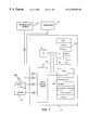
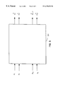
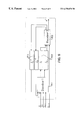
- FIG. 1 depicts schematically an electronic device incorporating a coder according to a first embodiment of the present invention
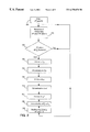
- FIG. 2 depicts schematically an operating flow diagram of a coder according to the first embodiment of the present invention, as illustrated in FIG. 1;
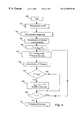
- FIG. 3 depicts schematically a flow diagram describing the steps of determination of an interlacer used in the device illustrated in FIG. 1;
- FIG. 4 depicts schematically a coder according to the second embodiment of the present invention.
- FIG. 5 depicts schematically the general form of interlacers acting on several sequences of symbols to be coded
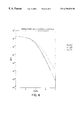
- FIG. 6 depicts a performance curve of particular examples of methods and devices according to the second embodiment of the present invention.
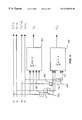
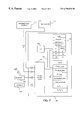
- FIG. 7 depicts schematically an electronic device incorporating a coder according to a second embodiment of the present invention.
- FIG. 8 depicts schematically an operating flow diagram of a coder according to the second embodiment of the present invention, as illustrated in FIG. 7;
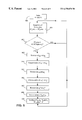
- FIG. 9 depicts schematically a decoding device to which the present invention relates.
- a length of sequence a equal to M.N 0 is chosen, which amounts to determining the length (that is to say the number of binary data) of the sequence u incorporated in the sequence a as being equal to M.N 0 minus the degree of g(x).
- an interlacer In order to determine the sequence a*(x), which has, after permutation, the same binary data as the sequence a, but in a different order, an interlacer is chosen, a representation of which can be given as follows: the binary data of the sequence a being arranged in a table of N 0 columns and M rows, there is performed on these data at least one permutation in a set of permutations including, on the one hand, the automorphisms of the binary cyclic code of length N 0 and with the generator polynomial g(x), permuting with each other at least two of the N 0 columns of the table and, on the other hand, the permutations operating solely on data in one and the same column and permuting with each other at least two of the said data items, and only one or more permutations of this set.
- the inventors have selected the following permutations, which have the advantage of constituting only a small family, all the members of which can be tested in order to choose the most effective permutation.
- f will be equal to 16 and the sequence a * begins with the binary data: a 0 , a 16 , a 32 , a 13 , a 29 , a 10 , etc . . .
- the selection logic is as follows: first of all g(x) of degree m, not divisible by a square polynomial, is chosen. This choice fixes the value of N 0 as being the smallest integer such that g(x) divides x N0 ⁇ 1. In addition, the fact that the polynomial g(x) is not divisible by a square polynomial implies that N 0 is an odd number. Then h 1 (x) and h 2 (x) are chosen of any degree but preferentially at most equal to the degree m of g(x) since the maximum of the degrees of these three polynomials g(x), h 1 (x) and h 2 (x) is a determining factor in the complexity of the decoder.
- An odd integer M is then chosen and the cycle of 2 modulo M.N 0 is calculated.
- N 0 7.
- the inventors have tested the polynomials a(x) divisible by g(x) and of weight equal successively to 2, 3, 4, 5, 6 and 7, and such that if this weight is greater than or equal to 5, then the weight of a(x), denoted W(a(x)), is equal to the weight of a(x) modulo x 15 +1.
- the numbers e, non-congruent at 1, modulo N 0 can be used in particular.
- FIGS. 1 to 3 The description of a particular embodiment of the present invention will now be continued with regard to FIGS. 1 to 3 .
- FIG. 1 illustrates schematically the constitution of a network station or computer coding station, in the form of a block diagram.
- This station has a keyboard 111 , a screen 109 , an external information source 110 and a radio transmitter 106 , conjointly connected to an input/output port 103 of a processing card 101 .
- the processing card 101 has, connected together by an address and data bus 102 :
- a central processing unit 100 a central processing unit 100 ;
- ROM 105 a read-only memory ROM 105 ;
- FIG. 1 Each of the components illustrated in FIG. 1 is well known to persons skilled in the art of microcomputers and transmission systems and, more generally, information processing systems. These common elements are therefore not described here. It will be observed, however, that:
- the information source 110 is, for example, an interface peripheral, a sensor, a demodulator, an external memory or another information processing system (not shown), and is preferentially adapted to supply sequences of signals representing speech, service messages or multimedia data, in the form of sequences of binary data,
- the radio transmitter 106 is adapted to implement a packet transmission protocol on a non-cable channel, and to transmit these packets on such a channel.
- register designates, in each of the memories 104 and 105 , both a memory area of low capacity (a few binary data) and a memory area of large capacity (making it possible to store an entire program).
- the random access memory 104 stores data, variables and intermediate processing results, in memory registers bearing, in the description, the same names as the data whose values they store.
- the random access memory 104 has notably:
- N o _data which stores an integer number corresponding to the number of binary data n-m in the register “binary_data”,
- permuted_data in which there are stored, in the order of their arrival on the bus 102 , the permuted binary data, as described with regard to FIG. 2, in the form of a sequence a *, and
- a register “a, b, c” in which there are stored, in the order in which they are determined by the central unit 100 , the binary data of the sequence currently being processed.
- the read-only memory 105 is adapted to store, in registers which, for convenience, have the same names as the data which they store:
- the central processing unit 100 is adapted to implement the flow diagram described in FIG. 2 .
- the central unit 100 determines whether or not the integer number stored in the register “N o _data” is equal to the product M.N 0 from which the degree of g(x) is subtracted, M, N 0 and the degree m of g(x) being values stored in the read-only memory 105 .
- the operation 301 is reiterated.
- the division of the polynomial u(x) associated with the sequence of binary data stored in the register “primary_data” by the polynomial g(x) is effected, up to the last term (of the highest degree) of u(x), using, for this purpose, the register “intermediate_remainder”, the remainder of this division is stored in memory in the register “final remainder”.
- the binary data stored in the register “final_remainder” are juxtaposed at the end of the sequence u in order to form the sequence a.
- the binary data of the sequence a are stored in memory in the register “a, b, c”.
- the binary data of the sequence a are successively read from the register “a, b, c”, in the order described by the table “interlacer” stored in the read-only memory 105 .
- the data which result successively from this reading are stored in memory in the register “permuted_data” of the read-only memory 104 .
- the division of the polynomial a*(x) associated with the sequence of permuted binary data stored in the register “permuted_data” by the polynomial g(x) is effected, using, for this purpose, the register “intermediate_remainder”.
- the result of this division is stored in memory in the register “a, b c”, and corresponds to the binary data of the sequence c.
- sequences b and c are determined by effecting the product of the polynomials associated with the sequences b and c stored in the register “a, b, c” of the random access memory 104 , and respectively the polynomials h 1 ,(x) and h 2 (x).
- sequences a, b, and c are sent, using for this purpose the sender 106 .
- the registers of the memory 104 are initialised again, in particular the counter “N o _data is reset to “0” and the operation 301 is reiterated.
- sequence a is sent as a whole, but only a sub-set, for example one data item out of two, of each of the sequences b and c is sent.
- This variant is known to persons skilled in the art as puncturing.
- FIG. 3 depicts the steps of an algorithm determining the value of e specifying the interlacer to use. These steps can be performed by a computer of a known type (not depicted), in which the registers “N 0 ”, “M”,“interlacer”, “d”, “d max ”, “e” and “j” are situated, in the random access memory.
- the divisions of the polynomials x i ⁇ 1 by g(x) are effected successively, commencing with a value of i equal to the degree m of g(x) and progressively incrementing i, with an incrementation step of 1, until the remainder of the division is nil, modulo 2 .
- the value of i is put in the register N 0 . It will be recalled that the division performed here is effected, modulo 2 , on the coefficients of the ascending powers of x i ⁇ 1.
- a length of sequence a equal to M.N 0 is chosen, which amounts to determining the length (that is to say the number of binary data) of the sequence u incorporated in the sequence a as being equal to M.N 0 minus the degree m of g(x).
- f is equal to a power of 2 different from 1, modulo M.N 0 , this permutation is indeed of the type stated.
- the central unit 100 determines the successive powers of 2 modulo M.N 0 , in order to obtain what is referred to as the cycle of 2, modulo M.N 0 , this cycle being completed as soon as one of the powers of 2 is equal to 1, modulo M.N 0 .
- the number of terms j of this cycle is stored in the register “j”.
- the process is limited to the analysis of the distance of the sequences with the nil sequence, the polynomials a(x) are enumerated by ascending weight, the sum of the weights of the sequences in one and the same triplet (a, b, c) is measured and a search is made for the minimum weight for a given e, for the sequences a of low weight, and, once all these minimum weights have been determined for e in the cycle of 2, for the value of e which corresponds to the highest weight.
- the distance is then stored in the register “d” of the random access memory 104 .
- the value stored in the register “d” is greater than the value stored in the register “d max ”, then, during the operation 508 , the value of the register “d max ” is modified in order to take the value d and the value of the l-th element of the cycle considered is stored in memory in the register “e”.
- the triplet (a, b, c) is constructed as follows:
- a permutation P is chosen which transforms any word of the binary cyclic code of length N 0 and with a generator polynomial g(x) into a word of the binary cyclic code of length N 2 and with a generator polynomial g 2 (x). It will be noted that such a permutation exists only for the polynomials g 2 (x) generating cyclic codes equivalent to Cg. This verification is well known to persons skilled in the art and for this reference should be made to page 234 of the book by Mrs F. J. MACWILLIAMS and Mr N. J. A. SLOANE mentioned above;
- the permutation which, from the sequence a, associated with the polynomial a(x) divisible by g(x), produces the sequence a**, associated with the polynomial a**(x), divisible by g 2 (x), is then produced by any permutation producing, from a(x), a first sequence a*(x) divisible by g(x) as explained above, followed by the permutation P which has just been introduced and which acts on the columns of the table with M rows and N 0 columns containing first of all a and next a * in order to permute these columns with each other and produce a**.
- passage at throughputs of a quarter or less, by adding one or more additional interlacers, is effected for each interlacer, by applying the principles set out above.
- puncturing can be used to raise the throughput of the code. It will be recalled that puncturing consists of transmitting only some of the check symbols.
- devices which are the object of the present invention are advantageously produced by implementing, in order to effect the arithmetic calculations, polynomial multiplication, polynomial division, the function of interlacing and the functions of elementary decoding, dedicated circuits not including a processor (such a processor can nevertheless be used for controlling the operation of these devices).
- dedicated circuits not including a processor (such a processor can nevertheless be used for controlling the operation of these devices).
- the use of such dedicated circuits makes it possible in fact to reach higher information flow rates.
- the throughput is, without puncturing, close to one third since, for a sequence of n-m symbols to be coded, there are two sequences of n check symbols.
- throughputs greater than 1/3 are considered, obtained without puncturing; for two sequences of n-mn symbols to be coded, two sequences of n check symbols are for example supplied, that is to say a throughput close to one half.
- a class of algebraic interlacers to be used with turbocoders with a throughput close to one third is presented.
- the main advantage of these interlacers is to preserve the divisibility of the information polynomials by a given polynomial g(x) which partially characterises the coder. As a result the probability of error per coded information bit is better independent of the position of the bits in the information sequence.
- the algebraic description of these interlacers makes their enumeration and individual evaluation possible. In addition, it is hoped that the performance of this small set of interlacers is representative of the performance of all the interlacers.
- the second embodiment is concerned particularly with throughputs greater than or close to one half, without the use of puncturing methods.
- h i , f l and g are polynomials with binary coefficients of indeterminate x representing the delay operator.
- v aG, which is a (K+2)-tuple of sequences of indeterminate x:
- sequences rather than “polynomials” is written here, since the sums are not necessarily multiples of g and, if they are not, division by g makes a sequence infinite and ultimately periodic.
- a l * represents the sequence obtained from the sequence a i by permutation of its coefficients.
- the transformation at each sequence a i into the sequence a l * is referred to as “interlacing” (see for example the article by Messrs. C. BERROU and A. GLAVIEUX entitled “Near Optimum error-correcting coding and decoding: turbo-codes” published by IEEE Transections on Communication, Volume COM-44, pages 1261 to 1271, in October 1996).
- FIG. 4 gives an illustration of a coder performing this operation.
- the coder sends, at the output:
- a sequence of check symbols formed by first of all interlacing each information sequence a i by an interlacer l l (interlacers 402 to 405 ) in order to supply a sequence a i *, then effecting the sum of the products of the polynomials associated with the sequences a i * and predetermined polynomials f l and dividing this sum by a predetermined polynomial g (coder 406 ).
- each sequence a i * can contains symbols of the sequence a j with j different from i.
- each interlacer l i has:
- At least one permutation in a set of permutations including, on the one hand, the automorphisms of the binary cyclic code of length N 0 and with a generator polynomial g(x), permuting with each other at least two of the N 0 columns of the table and, on the other hand, the permutations working solely on the data of the same column and permuting with each other at least two of the said data, and
- N 0 be the smallest integer such that g(x) divides x N0 +1.
- n M.N 0 .
- the polynomial g(x) is then a divisor of the polynomial x n +1.
- n can be chosen amongst the values 15, 45, 75, . . . , 225, . . . , 405, . . .
- Other details concerning these divisibility properties can be found in the work by W. W. PETERSON and E. J. WELDON entitled “Error-correcting codes ” published by MIT Press, Cambridge, Mass., 1972.
- u i polynomial u i (x) of formal degree n-m ⁇ 1 with binary coefficients.
- the resulting K-tuple a (a 1 , . . . , a K ) is then coded in order to produce two check sequences.
- n there are 42 numbers e which are each the residue, modulo 147 , of a power of 2.
- the corresponding turbocode was simulated on an additive white gaussian noise channel (known to persons skilled in the art under the English acronym “AWGN” standing for “Additive White Gaussian Noise”), for different values of the ratio between the energy per bit E b and the noise power per hertz (also referred to as the noise spectral density), N.
- AWGN additive white gaussian noise channel
- v [a 1 , a 2 , a 3 , ( ⁇ a i h i )/ g, ( ⁇ a i *f i )/ g]
- An element which influences the minimum distances of such a code is the minimum number of non-nil components of the 5-tuple v.
- none of the polynomials h i and f j is nil modulo x N0 +1, where N 0 is the smallest integer such that g(x) divides x N0 +1, N 0 being odd since the polynomial g(x) is not divisible by any polynomial square, and
- v [a 1 , . . . , a k , ( ⁇ a i h i,1 )/ g, ( ⁇ a i ( x e2 ) h i,2 )/ g, . . . , ( ⁇ a i ( x eN0,k′′ ) h i,k )/ g]
- Each non-nil v in the code generated by G always contains at least N 1 ⁇ K+1 non-nil components if, for each integer number r such that 1 ⁇ r ⁇ N 1 ⁇ K, each sub-matrix r ⁇ r of G extracted from its last N 1 ⁇ K columns and where h 1,j (x) is replaced by h i,j (x dj ), has a non-nil determinant, module x N0 +1.
- ⁇ is a matrix 2 ⁇ K on GF(2 m ).
- e power of 2 modulo n any element in the second row of ⁇ will be replaced by its e th power and the transposed matrix of this matrix will be denoted ⁇ .
- the elements of ⁇ will then be interpreted as polynomials of degree m ⁇ 1 of indeterminate x, and will be divided by g(x) or by any other divisor polynomial of x N0 +1 and the resulting matrix will be called P(x).
- I K is the identity matrix of dimension K.
- this coder G can be used as a turbocoder. By simulation, it is then possible to choose the best value of e.
- N 1 ⁇ K>2 can be treated in a similar fashion.
- the transposed matrix of this matrix is then denoted ⁇ , the elements of ⁇ are interpreted as polynomials of degree m ⁇ 1 of indeterminate x, they are divided by g(x) and the resulting matrix of dimensions K ⁇ (N ⁇ K) is termed P(x).
- the coders G [I K P(x)] obtained for different values of (M 1 ⁇ 1)-tuple (e 2 , . . . e M1 ) are then analysed by simulations and the best can be selected.
- FIG. 7 illustrates schematically the constitution of a network station or computer coding station, in the form of a block diagram.
- This station includes a keyboard 711 , a screen 709 , an external information source 710 and a radio transmitter 706 , conjointly connected to an input/output port 703 of a processing card 701 .
- the processing card 701 has, connected together by an address and data bus 702 :
- a central processing unit 700 a central processing unit 700 ;
- RAM 704 a random access memory RAM 704 ;
- FIG. 7 Each of the elements illustrated in FIG. 7 is well known to persons skilled in the art of microcomputers and transmission systems and, more generally, information processing systems. These common elements are therefore not described here. It should however be noted that:
- the information source 710 is, for example, an interface peripheral, a sensor, a demodulator, an external memory or another information processing system (not shown), and is preferentially adapted to supply sequences of signals representing speech, service messages or multimedia data, in the form of sequences of binary data,
- the radio transmitter 706 is adapted to implement a packet transmission protocol on a nonsable channel and to transmit these packets on such a channel.
- register designates, in each of the memories 704 and 705 , both a memory area of low capacity (a few binary data) and a memory area of large capacity enabling an entire program to be stored).
- the random access memory 704 stores data, variables and intermediate processing results, in memory registers bearing, in the description, the same names as the data whose values they store.
- the random access memory 704 contains notably:
- a register “primary_data” in which there are stored, in the order of their arrival on the bus 702 , the binary data coming from the information source 710 , in the form of two sequences, u 1 and u 2 , next supplemented in order to form two sequences a hd 1 and a 2 ,
- permuted_data in which there are stored, in the order of their transmission on the bus 702 , the permuted binary data, as described with regard to FIG. 8, in the form of two sequences, a 1 * and a 2 *,
- the read only memory 705 is adapted to store, in registers which, for convenience, bear the same names as the data which they store:
- interlacers considered here are respectively of type “x to x e1 38 and “x to x e2 ” described above.
- the central processing unit 700 is adapted to implement the flow diagram described in FIG. 8 .
- the central unit 700 first of all constitutes the sequence u 1 and then the sequence u 2 , with the primary data coming from the information source 710 .
- the central unit 700 determines whether or not the integer number stored in the register “No_data” is equal to the product M.N 0 from which the degree m of g(x), is subtracted M, N 0 and the degree m of g(x) being values stored in the random access memory 705 .
- the operation 801 is reiterated.
- the divisions of the polynomials u 1 (x) and u 2 (x) respectively associated with the sequences of binary data u 1 and u 2 stored in the register “primary_data”, by the polynomial g(x) are effected, up to the last terms (of the highest degrees) of u 1 (x) and u 2 (x), using, for this purpose the register “intermediate_remainder”.
- the remainders of these divisions are stored in memory in the register “final_remainder”.
- the binary data stored in the register “final_remainder are respectively juxtaposed with the ends of the sequences u 1 and u 2 in order to form the sequences a 1 and a 2 .
- the binary data of the sequences a 1 and a 2 are stored in memory in the registers “ a 1 , b 1 , c 1 ” and “ a 2 , b 2 , c 2 ”.
- the binary data of the sequence a 1 are respectively and successively read in the register “ a 1 , b 1 , c 1 ”, in the order described by the table “interlacer1” stored in the random access memory 705 , and
- the binary data of the sequence a 2 are respectively and successively read in the register “ a 2 , b 2 , c 2 ”, in the order described by the table “interlacer2” stored in the random access memory 705 .
- the data which results successively from these readings are respectively stored in memory in the register “permuted_data” of the random access memory 704 .
- the divisions of the polynomials a 1 *(x) and a 2 *(x), respectively associated with the sequences of permuted binary data stored in the register “permuted_data”, by the polynomial g(x) are effected, using for this purpose the register “intermediate_remainder”.
- the results of these divisions are stored in memory in the register a 1 , b 1 , c 1 ” and “ a 2 , b 2 , c 2 ”, and correspond to the binary data of the sequences c 1 and c 2 .
- the sequence b s is determined by effecting the product of the polynomials associated with the sequences b 1 and b 2 stored in the registers “ a 1 , b 1 , c 1 ” and “ a 2 , b 2 , c 2 ” in the random access memory 704 and respectively the polynomials h(x) and f(x);
- the sequence c s is determined by effecting the product of the polynomials associated with the sequences c 1 and C 2 stored in the registers “ a 1 , b 1 , c 1 ” and “ a 2 , b 2 , c 2 ” in the random access memory 704 and respectively the polynomials f(x) and h(x).
- the sequences a 1 , a 2 , b s and c s are transmitted, using for this purpose the transmitter 706 .
- the registers of the memory 704 are once again initialised, in particular the counter No_data is reset to “0” and the operation 801 is reiterated.
- sequences a 1 and a 2 are sent as a whole, but only a subset, for example one data item out of two, of each of the sequences b s and c s is sent.
- This variant is known to persons skilled in the art as puncturing.
- a decoding device adapted to decode the sequences sent by the decoding device illustrated in FIGS. 4 to 8 , has, essentially:
- a decoder 901 corresponding to the coder 401 , which receives the estimations of transmitted sequences, v 1 to v K+1 as well as K extrinsic information sequences w′′′ 1 to w′′′ K disclosed below, and supplies K estimation sequences a posteriori w 1 to w K ,
- K interlacers 902 identical to the interlacers 402 to 405 used in the coder, which receive respectively the sequences w 1 to w K and interlace then respectively as w′ 1 to w′ K ,
- a second decoder 903 corresponding to the coder 406 receiving the sequences w′ 1 to w′ K as well as the sequence v K+2 and supplies on the one hand K a posteriori estimation sequences w′′ 1 to w′′ K and on the other hand an estimated sequence a′, and
- K deinterlacers 904 the reverse of the interlacers 402 , to 405 , receiving the sequences w′′ 1 to w′′ K and supplying the sequences w′′′ 1 to w′′′ K .
- the estimated sequence a′ is taken into account only following a predetermined number of iterations (see the article “Near Shannon limit error-correcting coding and decoding: turbocodes” cited above).
- the interlacers and deinterlacers used for decoding each have the same characteristics as the interlacers used for coding and preferentially, or of the type “x to x e ”.
- the exponents e ij are equal.
- the value of the exponents e ij are all powers of 2.
Landscapes
- Engineering & Computer Science (AREA)
- Theoretical Computer Science (AREA)
- Physics & Mathematics (AREA)
- Probability & Statistics with Applications (AREA)
- Error Detection And Correction (AREA)
- Detection And Correction Of Errors (AREA)
Applications Claiming Priority (4)
| Application Number | Priority Date | Filing Date | Title |
|---|---|---|---|
| FR9716669A FR2773287A1 (fr) | 1997-12-30 | 1997-12-30 | Entrelaceur, dispositif de codage, procede de permutation, procede de codage, dispositif et procede de decodage et systemes les mettant en oeuvre |
| FR9716669 | 1997-12-30 | ||
| FR9814084A FR2785742A1 (fr) | 1998-11-09 | 1998-11-09 | Entrelaceur, dispositif de codage, procede de permutation, procede de codage, dispositif et procede de decodage et systemes les mettant en oeuvre |
| FR9814084 | 1998-11-09 |
Publications (1)
| Publication Number | Publication Date |
|---|---|
| US6370670B1 true US6370670B1 (en) | 2002-04-09 |
Family
ID=26234037
Family Applications (1)
| Application Number | Title | Priority Date | Filing Date |
|---|---|---|---|
| US09/222,849 Expired - Fee Related US6370670B1 (en) | 1997-12-30 | 1998-12-30 | Interlacer, coding device, permutation method, coding method, decoding device and method and systems using them |
Country Status (6)
| Country | Link |
|---|---|
| US (1) | US6370670B1 (de) |
| EP (1) | EP0928071B8 (de) |
| JP (1) | JP4124893B2 (de) |
| KR (1) | KR100341266B1 (de) |
| CN (1) | CN1213541C (de) |
| DE (1) | DE69837077T2 (de) |
Cited By (8)
| Publication number | Priority date | Publication date | Assignee | Title |
|---|---|---|---|---|
| US20020099997A1 (en) * | 2000-10-10 | 2002-07-25 | Philippe Piret | Turbocoding methods with a large minimum distance, and systems for implementing them |
| US6536001B1 (en) * | 1999-03-11 | 2003-03-18 | Globespanvirata, Inc. | Circuit and method for convolutional interleaving using a single modulo operation |
| US6560362B1 (en) * | 1998-11-09 | 2003-05-06 | Canon Kabushiki Kaisha | Encoding and interleaving device and method for serial or hybrid turbocodes |
| US6578170B1 (en) * | 1998-12-30 | 2003-06-10 | Canon Kabushiki Kaisha | Coding device and method, decoding device and method and systems using them |
| US6857096B1 (en) * | 1999-04-13 | 2005-02-15 | Canon Kabushiki Kaisha | Method of the ARQ type for a transmission method using turbocodes, and associated device |
| US20050138533A1 (en) * | 2003-09-29 | 2005-06-23 | Canon Kabushiki Kaisha | Encoding/decoding device using a reed-solomon encoder/decoder |
| US20050216813A1 (en) * | 2004-03-23 | 2005-09-29 | Shaun Cutts | Fixed content distributed data storage using permutation ring encoding |
| US20100169500A1 (en) * | 2007-10-09 | 2010-07-01 | Cleversafe, Inc. | Systems, methods, and apparatus for matching a connection request with a network interface adapted for use with a with a dispersed data storage network |
Families Citing this family (16)
| Publication number | Priority date | Publication date | Assignee | Title |
|---|---|---|---|---|
| US6427214B1 (en) | 1998-09-29 | 2002-07-30 | Nortel Networks Limited | Interleaver using co-set partitioning |
| FR2785743A1 (fr) * | 1998-11-09 | 2000-05-12 | Canon Kk | Dispositif et procede d'adaptation des turbocodeurs et des decodeurs associes a des sequences de longueur variable |
| US6625234B1 (en) | 1998-12-10 | 2003-09-23 | Nortel Networks Limited | Efficient implementations of proposed turbo code interleavers for third generation code division multiple access |
| FR2790621B1 (fr) | 1999-03-05 | 2001-12-21 | Canon Kk | Dispositif et procede d'entrelacement pour turbocodage et turbodecodage |
| FR2805103A1 (fr) * | 2000-02-10 | 2001-08-17 | Canon Kk | Procede de permutation pour turbo-codage convolutif de donnees |
| FR2800950A1 (fr) * | 1999-11-04 | 2001-05-11 | Canon Kk | Procede d'entrelacement pour turbo-codage convolutif de donnees |
| EP1098445B1 (de) * | 1999-11-04 | 2011-02-16 | Canon Kabushiki Kaisha | Verschachtelungsverfahren für Datenturbokodierung |
| FR2801446B1 (fr) * | 1999-11-18 | 2002-04-19 | Canon Kk | Procede et dispositif de codage, procede et dispositif de decodage, et systemes les mettant en oeuvre |
| FR2802735B1 (fr) * | 1999-12-20 | 2002-03-29 | Canon Kk | Procede et dispositif de codage, procede et dispositif de decodage, et systemes les mettant en oeuvre |
| FR2804806B1 (fr) * | 2000-02-08 | 2002-05-03 | Canon Kk | Procede et dispositif d'entrelacement, procedes et dispositifs de codage et de decodage et systemes les mettant en oeuvre |
| FR2807895B1 (fr) | 2000-04-18 | 2002-06-07 | Canon Kk | Procedes et dispositifs de codage et de decodage et systemes les mettant en oeuvre |
| FR2813723B1 (fr) * | 2000-09-04 | 2002-11-08 | Canon Kk | Procedes de turbocodage circulaire de haut rendement, et systemes pour leur mise en oeuvre |
| FR2819955B1 (fr) * | 2001-01-23 | 2003-05-16 | Canon Kk | Procedes de turbocodage et turbodecodage (4,2), et systemes pour leur mise en oeuvre |
| JP4507443B2 (ja) * | 2001-04-19 | 2010-07-21 | 日本電気株式会社 | インターリーブ方法及びインターリーブ装置 |
| FR2829329B1 (fr) * | 2001-09-05 | 2003-11-28 | Canon Kk | Procedes de turbocodage a entrelaceurs verrous, et systemes pour leur mise en oeuvre |
| CN109036440B (zh) * | 2017-06-08 | 2022-04-01 | 腾讯科技(深圳)有限公司 | 多人会话的方法及系统 |
Citations (7)
| Publication number | Priority date | Publication date | Assignee | Title |
|---|---|---|---|---|
| US3988538A (en) * | 1974-03-07 | 1976-10-26 | International Standard Electric Corporation | Digital data scrambler and descrambler |
| US4488302A (en) * | 1983-02-11 | 1984-12-11 | At&T Bell Laboratories | Burst error correction using cyclic block codes |
| US5438590A (en) * | 1993-05-24 | 1995-08-01 | Comstream Corporation | Transmitting and receiving apparatus and method including punctured convolutional encoding and decoding |
| US5844989A (en) * | 1995-06-05 | 1998-12-01 | Matsushita Electric Industrial Co., Ltd. | Data scrambling method, data scrambling apparatus, data descrambling method, and data descrambling apparatus |
| US5966447A (en) * | 1996-06-04 | 1999-10-12 | Matsushita Electric Industrial Co., Ltd. | Data scrambling method, data scrambling apparatus, data descrambling method, and data descrambling apparatus |
| US6034996A (en) * | 1997-06-19 | 2000-03-07 | Globespan, Inc. | System and method for concatenating reed-solomon and trellis codes |
| US6151296A (en) * | 1997-06-19 | 2000-11-21 | Qualcomm Incorporated | Bit interleaving for orthogonal frequency division multiplexing in the transmission of digital signals |
Family Cites Families (2)
| Publication number | Priority date | Publication date | Assignee | Title |
|---|---|---|---|---|
| US4567594A (en) * | 1983-06-07 | 1986-01-28 | Burroughs Corporation | Reed-Solomon error detecting and correcting system employing pipelined processors |
| US4907233A (en) * | 1988-05-18 | 1990-03-06 | The United States Of America As Represented By The Administrator Of The National Aeronautics And Space Administration | VLSI single-chip (255,223) Reed-Solomon encoder with interleaver |
-
1998
- 1998-12-23 EP EP98403283A patent/EP0928071B8/de not_active Expired - Lifetime
- 1998-12-23 DE DE69837077T patent/DE69837077T2/de not_active Expired - Lifetime
- 1998-12-30 CN CNB981259502A patent/CN1213541C/zh not_active Expired - Fee Related
- 1998-12-30 KR KR1019980062589A patent/KR100341266B1/ko not_active IP Right Cessation
- 1998-12-30 US US09/222,849 patent/US6370670B1/en not_active Expired - Fee Related
-
1999
- 1999-01-04 JP JP00024199A patent/JP4124893B2/ja not_active Expired - Fee Related
Patent Citations (8)
| Publication number | Priority date | Publication date | Assignee | Title |
|---|---|---|---|---|
| US3988538A (en) * | 1974-03-07 | 1976-10-26 | International Standard Electric Corporation | Digital data scrambler and descrambler |
| US4488302A (en) * | 1983-02-11 | 1984-12-11 | At&T Bell Laboratories | Burst error correction using cyclic block codes |
| US5438590A (en) * | 1993-05-24 | 1995-08-01 | Comstream Corporation | Transmitting and receiving apparatus and method including punctured convolutional encoding and decoding |
| US5844989A (en) * | 1995-06-05 | 1998-12-01 | Matsushita Electric Industrial Co., Ltd. | Data scrambling method, data scrambling apparatus, data descrambling method, and data descrambling apparatus |
| US5978486A (en) * | 1995-06-05 | 1999-11-02 | Matsushita Electric Industrial Co., Ltd. | Data scrambling method, data scrambling apparatus, data descrambling method, and data descrambling apparatus |
| US5966447A (en) * | 1996-06-04 | 1999-10-12 | Matsushita Electric Industrial Co., Ltd. | Data scrambling method, data scrambling apparatus, data descrambling method, and data descrambling apparatus |
| US6034996A (en) * | 1997-06-19 | 2000-03-07 | Globespan, Inc. | System and method for concatenating reed-solomon and trellis codes |
| US6151296A (en) * | 1997-06-19 | 2000-11-21 | Qualcomm Incorporated | Bit interleaving for orthogonal frequency division multiplexing in the transmission of digital signals |
Non-Patent Citations (14)
| Title |
|---|
| A. S. Barbulescu and S. S. Pietrobon, "Interleaver Design for Turbo Codes", Electronic Letters, vol. 30, No. 25, Dec. 8, 1994.* * |
| A. S. Barbulescu and S. S. Pietrobon, "Terminating the Trellis of Turbo-codes in the Same State", Electronic Letters, vol. 31, No. 1, Jan. 5, 1995.* * |
| Barbulescu Et Al.: "Interleaver design for turbo codes", Electronics Letters, vol. 30, No. 25, Dec. 8, 1995, pp. 2107-2108, XP000501850, Stevenage, Herts, GB. |
| Berrou Et Al.: "Frame oriented convolutional turbo codes", Electronics Letters, vol. 32, No. 15, Jul. 18, 1996, pp. 1362-1364, XP000625424, Stevenage, Herts, GB. |
| Berrou Et Al.: "Near Optimum error correcting coding and decoding ; turbo codes", IEEE Transactions on Communications, vol. 44, No. 10, Oct., 1996, pp. 1261-1271, XP000629465, IEEE Transactions on Communications paragraphs Uniform interleaving et "Nonuniform interleaving". |
| Claude Berrou and Alain Glavieux, "Near Optimum Error Correcting Coding and Decoding: Turbo-Codes", IEEE Transactions on Communications, vol. 44, No. 10, October 1996.* * |
| D. Divsalar, and F. Pollara "Hybrid Concatenated Codes and Iterative Decoding", NASA, JPL, TDA Progress Report 42-130, August 15, 1997.* * |
| D. Divsalar, and F. Pollara "On the Desing of Turbo Codes", NASA, JPL, TDA Progress Report 42-123, Nov. 15, 1995.* * |
| Danny T. Chi "A New Algorithm for Error Correcting Single Burst Errors With Reed-Soloman Code", IEEE, 1991.* * |
| Danny T. Chi "A New Block Helical Interleaver", IEEE, 1992.* * |
| Divsalar Et Al.: "Turbo codes for PCS applications", Proceedings of the Int'l Conference on Communications, vol. 1, Jun. 18-22, 1995, pp. 54-59, XP000532968, Seattle, US, paragraph "Interleaver design". |
| E. Dunscombe and F. C. Piper, "Optimal Interleaving Scheme for Convolutional Codes", Electronic Letters, vol. 25, No. 22, October 26, 1989.* * |
| S. Benedetto, D. Divsalar, G. Montorsi, and F. Pollara, "Soft-Output Decoding Algorithms in Iterative Decoding of Turbo Codes", NASA, JPL, TDA Progress Report 42-124, Feb. 15, 1996.* * |
| Wicker (Stephen B. Wicker, "Error Control Systems", Prentice Hall, 1995).* * |
Cited By (11)
| Publication number | Priority date | Publication date | Assignee | Title |
|---|---|---|---|---|
| US6560362B1 (en) * | 1998-11-09 | 2003-05-06 | Canon Kabushiki Kaisha | Encoding and interleaving device and method for serial or hybrid turbocodes |
| US6578170B1 (en) * | 1998-12-30 | 2003-06-10 | Canon Kabushiki Kaisha | Coding device and method, decoding device and method and systems using them |
| US6536001B1 (en) * | 1999-03-11 | 2003-03-18 | Globespanvirata, Inc. | Circuit and method for convolutional interleaving using a single modulo operation |
| US6857096B1 (en) * | 1999-04-13 | 2005-02-15 | Canon Kabushiki Kaisha | Method of the ARQ type for a transmission method using turbocodes, and associated device |
| US20020099997A1 (en) * | 2000-10-10 | 2002-07-25 | Philippe Piret | Turbocoding methods with a large minimum distance, and systems for implementing them |
| US6993698B2 (en) * | 2000-10-10 | 2006-01-31 | Canon Kabushiki Kaisha | Turbocoding methods with a large minimum distance, and systems for implementing them |
| US20050138533A1 (en) * | 2003-09-29 | 2005-06-23 | Canon Kabushiki Kaisha | Encoding/decoding device using a reed-solomon encoder/decoder |
| US7404134B2 (en) | 2003-09-29 | 2008-07-22 | Canon Kabushiki Kaisha | Encoding/decoding device using a reed-solomon encoder/decoder |
| US20050216813A1 (en) * | 2004-03-23 | 2005-09-29 | Shaun Cutts | Fixed content distributed data storage using permutation ring encoding |
| US7240236B2 (en) * | 2004-03-23 | 2007-07-03 | Archivas, Inc. | Fixed content distributed data storage using permutation ring encoding |
| US20100169500A1 (en) * | 2007-10-09 | 2010-07-01 | Cleversafe, Inc. | Systems, methods, and apparatus for matching a connection request with a network interface adapted for use with a with a dispersed data storage network |
Also Published As
| Publication number | Publication date |
|---|---|
| JP4124893B2 (ja) | 2008-07-23 |
| CN1213541C (zh) | 2005-08-03 |
| DE69837077T2 (de) | 2007-06-21 |
| EP0928071B1 (de) | 2007-02-14 |
| CN1232323A (zh) | 1999-10-20 |
| DE69837077D1 (de) | 2007-03-29 |
| EP0928071A1 (de) | 1999-07-07 |
| EP0928071B8 (de) | 2007-04-25 |
| JPH11298339A (ja) | 1999-10-29 |
| KR100341266B1 (ko) | 2002-09-18 |
| KR19990063573A (ko) | 1999-07-26 |
Similar Documents
| Publication | Publication Date | Title |
|---|---|---|
| US6370670B1 (en) | Interlacer, coding device, permutation method, coding method, decoding device and method and systems using them | |
| US6766489B1 (en) | Device and method of adapting turbocoders and the associated decoders to sequences of variable length | |
| US6578170B1 (en) | Coding device and method, decoding device and method and systems using them | |
| Rankin et al. | Single parity check product codes | |
| RU2316111C2 (ru) | Устройство и способ кодирования-декодирования блоковых кодов низкой плотности с контролем на четность в системе мобильной связи | |
| US7069492B2 (en) | Method of interleaving a binary sequence | |
| US6304991B1 (en) | Turbo code interleaver using linear congruential sequence | |
| US6625762B1 (en) | Interleaving device and method for turbocoding and turbodecoding | |
| US6323788B1 (en) | Interleaving apparatus and method for use in serial concatenated convolutional code encoder in a mobile communication system | |
| US6543021B1 (en) | Method and device for coding and transmission using a sub-code of a product code | |
| EP1450494B1 (de) | Verschachtelungsverfahren und -vorrichtung mit parallelem Zugriff in der linearen und verschachtelten Addressierung | |
| CN1937473A (zh) | 随机存取多向cdma2000 turbo编码交织器 | |
| JP2000508849A (ja) | データ・ブロックの畳み込み符号化方法及び装置及び対応する復号方法及び装置 | |
| US6560362B1 (en) | Encoding and interleaving device and method for serial or hybrid turbocodes | |
| US6638318B1 (en) | Method and device for coding sequences of data, and associated decoding method and device | |
| US6993085B2 (en) | Encoding and decoding methods and devices and systems using them | |
| US6842871B2 (en) | Encoding method and device, decoding method and device, and systems using them | |
| Yoo et al. | Reverse rate matching for low-power LTE-advanced turbo decoders | |
| Benedetto et al. | Performance evaluation of parallel concatenated codes | |
| Couleaud | High gain coding schemes for space communications | |
| EP2826150B1 (de) | Turbocodierer | |
| Chiu | Polynomial representations of polar codes and decoding under overcomplete representations | |
| Mohammadi et al. | Variance of the turbo code performance bound over the interleavers | |
| Bohulu et al. | Interleaver Design for Turbo Codes Based on Complete Knowledge of Low-Weight Codewords of RSC Codes | |
| Lakshmi et al. | Area efficient implementation of short length QC-LDPC codes for Ultra-Reliable Low-Latency Communication (URLLC) application |
Legal Events
| Date | Code | Title | Description |
|---|---|---|---|
| AS | Assignment |
Owner name: CANON KABUSHIKI KAISHA, JAPAN Free format text: ASSIGNMENT OF ASSIGNORS INTEREST;ASSIGNORS:LE DANTEC, CLAUDE;PIRET,PHILIPPE;REEL/FRAME:009782/0949 Effective date: 19990212 |
|
| FPAY | Fee payment |
Year of fee payment: 4 |
|
| CC | Certificate of correction | ||
| FPAY | Fee payment |
Year of fee payment: 8 |
|
| REMI | Maintenance fee reminder mailed | ||
| LAPS | Lapse for failure to pay maintenance fees | ||
| STCH | Information on status: patent discontinuation |
Free format text: PATENT EXPIRED DUE TO NONPAYMENT OF MAINTENANCE FEES UNDER 37 CFR 1.362 |
|
| FP | Lapsed due to failure to pay maintenance fee |
Effective date: 20140409 |