US6367175B2 - Low turbulence air blast system - Google Patents

Low turbulence air blast system Download PDF

Info

Publication number
US6367175B2
US6367175B2 US09/840,247 US84024701A US6367175B2 US 6367175 B2 US6367175 B2 US 6367175B2 US 84024701 A US84024701 A US 84024701A US 6367175 B2 US6367175 B2 US 6367175B2
Authority
US
United States
Prior art keywords
channel
vehicle
air
air duct
blast system
Prior art date
Legal status (The legal status is an assumption and is not a legal conclusion. Google has not performed a legal analysis and makes no representation as to the accuracy of the status listed.)
Expired - Lifetime
Application number
US09/840,247
Other versions
US20010032401A1 (en
Inventor
Scott Lewis
Mike Weege
Greg Noah
Current Assignee (The listed assignees may be inaccurate. Google has not performed a legal analysis and makes no representation or warranty as to the accuracy of the list.)
JPMorgan Chase Bank NA
Stewart and Stevenson LLC
Original Assignee
S&S Trust
Priority date (The priority date is an assumption and is not a legal conclusion. Google has not performed a legal analysis and makes no representation as to the accuracy of the date listed.)
Filing date
Publication date
Application filed by S&S Trust filed Critical S&S Trust
Priority to US09/840,247 priority Critical patent/US6367175B2/en
Publication of US20010032401A1 publication Critical patent/US20010032401A1/en
Assigned to S&S TRUST reassignment S&S TRUST ASSIGNMENT OF ASSIGNORS INTEREST (SEE DOCUMENT FOR DETAILS). Assignors: NOAH, GREG, WEEGE, MIKE, LEWIS, SCOTT
Application granted granted Critical
Publication of US6367175B2 publication Critical patent/US6367175B2/en
Assigned to JPMORGAN CHASE BANK, N.A., AS COLLATERAL AGENT reassignment JPMORGAN CHASE BANK, N.A., AS COLLATERAL AGENT ASSIGNMENT OF ASSIGNORS INTEREST (SEE DOCUMENT FOR DETAILS). Assignors: STEWART & STEVENSON DISTRIBUTOR HOLDINGS LLC,, STEWART & STEVENSON LLC,, STEWART & STEVENSON PETROLEUM SERVICES LLC, STEWART & STEVENSON POWER PRODUCTS LLC,
Assigned to WACHOVIA BANK, NATIONAL ASSOCIATION, AS ADMINISTRATIVE AGENT reassignment WACHOVIA BANK, NATIONAL ASSOCIATION, AS ADMINISTRATIVE AGENT NOTICE OF GRANT OF SECURITY INTEREST Assignors: S&S TRUST
Assigned to STEWART & STEVENSON LLC reassignment STEWART & STEVENSON LLC ASSIGNMENT OF ASSIGNORS INTEREST (SEE DOCUMENT FOR DETAILS). Assignors: S&S TRUST
Assigned to S&S TRUST reassignment S&S TRUST TERMINATION AND RELEASE Assignors: WACHOVIA, N.A., AS ADMINISTRATIVE AGENT
Assigned to JPMORGAN CHASE BANK, N.A. reassignment JPMORGAN CHASE BANK, N.A. SECURITY INTEREST (SEE DOCUMENT FOR DETAILS). Assignors: STEWART & STEVENSON LLC
Assigned to STEWART & STEVENSON LLC reassignment STEWART & STEVENSON LLC RELEASE BY SECURED PARTY (SEE DOCUMENT FOR DETAILS). Assignors: JPMORGAN CHASE BANK N.A.
Assigned to KIRBY S&S LLC reassignment KIRBY S&S LLC ASSIGNMENT OF ASSIGNORS INTEREST (SEE DOCUMENT FOR DETAILS). Assignors: STEWART & STEVENSON LLC
Assigned to STEWART & STEVENSON LLC reassignment STEWART & STEVENSON LLC CHANGE OF NAME (SEE DOCUMENT FOR DETAILS). Assignors: KIRBY S&S LLC
Anticipated expiration legal-status Critical
Expired - Lifetime legal-status Critical Current

Links

Images

Classifications

    • EFIXED CONSTRUCTIONS
    • E01CONSTRUCTION OF ROADS, RAILWAYS, OR BRIDGES
    • E01HSTREET CLEANING; CLEANING OF PERMANENT WAYS; CLEANING BEACHES; DISPERSING OR PREVENTING FOG IN GENERAL CLEANING STREET OR RAILWAY FURNITURE OR TUNNEL WALLS
    • E01H5/00Removing snow or ice from roads or like surfaces; Grading or roughening snow or ice
    • E01H5/10Removing snow or ice from roads or like surfaces; Grading or roughening snow or ice by application of heat for melting snow or ice, whether cleared or not, combined or not with clearing or removing mud or water, e.g. burners for melting in situ, heated clearing instruments; Cleaning snow by blowing or suction only
    • E01H5/106Clearing snow or ice exclusively by means of rays or streams of gas or steam, or by suction with or without melting
    • AHUMAN NECESSITIES
    • A46BRUSHWARE
    • A46BBRUSHES
    • A46B13/00Brushes with driven brush bodies or carriers
    • A46B13/001Cylindrical or annular brush bodies
    • EFIXED CONSTRUCTIONS
    • E01CONSTRUCTION OF ROADS, RAILWAYS, OR BRIDGES
    • E01HSTREET CLEANING; CLEANING OF PERMANENT WAYS; CLEANING BEACHES; DISPERSING OR PREVENTING FOG IN GENERAL CLEANING STREET OR RAILWAY FURNITURE OR TUNNEL WALLS
    • E01H1/00Removing undesirable matter from roads or like surfaces, with or without moistening of the surface
    • E01H1/02Brushing apparatus, e.g. with auxiliary instruments for mechanically loosening dirt
    • E01H1/05Brushing apparatus, e.g. with auxiliary instruments for mechanically loosening dirt with driven brushes
    • E01H1/056Brushing apparatus, e.g. with auxiliary instruments for mechanically loosening dirt with driven brushes having horizontal axes
    • EFIXED CONSTRUCTIONS
    • E01CONSTRUCTION OF ROADS, RAILWAYS, OR BRIDGES
    • E01HSTREET CLEANING; CLEANING OF PERMANENT WAYS; CLEANING BEACHES; DISPERSING OR PREVENTING FOG IN GENERAL CLEANING STREET OR RAILWAY FURNITURE OR TUNNEL WALLS
    • E01H1/00Removing undesirable matter from roads or like surfaces, with or without moistening of the surface
    • E01H1/08Pneumatically dislodging or taking-up undesirable matter or small objects; Drying by heat only or by streams of gas; Cleaning by projecting abrasive particles
    • E01H1/0809Loosening or dislodging by blowing ; Drying by means of gas streams

Definitions

  • This invention relates generally to a method and apparatus for directing a snow or debris blowing air blast under vehicles. More particularly, this invention relates to an apparatus and method for directing a low turbulence vehicle-mounted air blast for use in clearing snow or debris from a road or runway.
  • Vehicle-mounted devices for use in clearing snow or debris from a road or runway typically include a front-mounted broom assembly and a rear-mounted air blast system as shown in FIG. 1 .
  • some prior art air blast systems are mounted between the front and rear axles.
  • the spinning broom on the front of the truck contacts the snow or debris on the runway and brushes the snow or debris both to the front and to one side. Then the snow or debris which has been swept to one side is blown farther across the runway by the air blast system.
  • the truck when it is desired to push the snow or debris to one side of the runway, specifically the left side as shown in the figure, the truck moves along the right side of the runway until it reaches the end. Upon reaching the end of the runway, the operator must re-configure the truck by repositioning the broom and redirecting the air blast. Note that in the truck moving up the runway on the right side of FIG. 1, the broom is positioned so that the near end is closest to the left or driver side of the truck going up the runway and the air blast is exiting the truck on the left side.
  • This switching of the direction of the air blast system and the changing of the angular orientation of the broom keeps the snow or debris moving from the right side of the runway to the left side of the runway.
  • the direction of the air blast at the rear end of the truck is controlled by the use of two multi-curved air ducts mounted on either side of the truck. These bends in the air ducts induce unwanted turbulence into the high velocity air flow.
  • the air duct on the left side at the rear of the truck comes down and the air blast system causes high velocity air to pass from the left side to the right side of the truck to blow the snow or debris in the same direction that it is pushed by the broom.
  • some prior art air blast systems use an air duct with vanes to regulate the flow of air to the left or right depending on the direction that the broom is facing.
  • the vanes are switched in order to change the direction of air flow from one side of the truck to the other.
  • the air blast is split in two, with only half of the air flow going to the left or right.
  • the orientation of the broom and the direction of the air blast system are both reconfigured for another pass in the opposite direction down the runway.
  • This reconfiguration of the truck for the second pass down the runway begins by first changing the direction of the air flow in the air blast system from one side to the other by repositioning the ducts or vanes. Following this repositioning, the broom in the front of the truck is repositioned.
  • the truck turnaround and reconfiguration time is a problem.
  • the system is less efficient due to the reduction of air flow and decreased air speed.
  • the air blast system should be positioned on the truck such that the blast of air moves the snow or debris from under the truck before it is compacted by the truck wheels.
  • the air ducts of the air blast system should be designed to minimize air turbulence and allow the air ducts to be pulled up under the truck when not in use.
  • the air blast system should be configured to create a powerful and efficient air flow which also operates as a vacuum to suction as much snow as possible from the surface of the runway.
  • the present invention is an apparatus and method for directing a low turbulence vehicle-mounted air blast for use in clearing snow or debris from a road or runway.
  • the high velocity air passes through the air ducts into the channel which passes under the central portion of the truck.
  • the air flow is not split in half, but is delivered in a single blast which powerfully blows the snow across the runway. Additionally, the passage of the high velocity air through the channel creates a vacuum which efficiently draws the snow and moisture off the runway surface and removes the snow from cracks in the runway.
  • FIG. 5 illustrates the air duct on the left side of the truck engaging the channel passing under the central portion of the truck to provide an air blast exiting on the right side of the truck.
  • the turbulence of the air flow in the air blast system is minimized by the reduction in the amount and severity of the bends in the air ducts as compared to those used in prior art trucks. Additionally, internal baffles within the air ducts are used to further reduce the air flow turbulence.
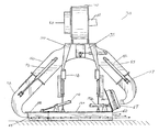
  • the air channel and air ducts are lowered toward the ground during operation. To eliminate the problem of the rear wheels compressing the snow on the runway, the air blast system has been moved to the central portion of the truck just behind the driver's cab. As may be seen in FIG. 5, the air duct on the left side of the truck is positioned adjacent to an air channel which passes under the truck. This positioning of the air blast system in front of the rear wheels also enables a better weight distribution on the truck.
  • both the air ducts and the channel may be pulled up under the chassis of the truck as shown in FIG. 4 and FIG. 7 .
  • FIG. 1 is a diagram illustrating the configuration of a truck mounted broom and air blast system in the prior art
  • FIG. 2 is a schematic diagram of the air blast system of the present invention configured for left-sided air blast
  • FIG. 3 is a diagram of the air blast system of the present invention configured for right-sided air blast
  • FIG. 4 illustrates a lateral perspective view of the vehicle mounted air blast system of the present invention drawn upwardly for road travel;
  • FIG. 5 illustrates a lateral perspective view of the vehicle mounted air blast system of the present invention engaged for operation
  • FIG. 6 illustrates a lateral perspective view of the air blast system with the left air duct engaged with the left air channel duct
  • FIG. 7 is a lateral perspective view of the air blast system with the air ducts and air channel withdrawn for road travel.
  • FIG. 1 illustrates the configuration of a truck mounted broom and air blast system in the prior art.
  • the vehicle 10 in FIG. 1 is shown proceeding up the runway 40 with the broom assembly 20 and air blast system 30 configured for directing the snow or debris to the left side of the vehicle 10 and the left side of the runway 40 .
  • the operator When the vehicle 10 reaches the end of the runway 40 , the operator must reconfigure the broom assembly 20 and air blast system 30 to the right side of the vehicle 10 such that the snow or debris is still directed to the left side of the runway 40 .
  • the operator has the retractable arcuate right air duct 57 fully extended from the right air duct 55 for engagement with the right air channel duct 67 in order to have the snow or debris directed to the left side of the runway.
  • the operator simply disengages the retractable arcuate right air duct 57 from the right air channel duct 67 and retracts the retractable arcuate right air duct 57 and raises the right air channel duct 67 .
  • the operator then extends the retractable arcuate left air duct 52 from the left air duct 50 , and engages the retractable arcuate left air duct 52 with the left air channel duct 65 as shown in FIG. 3 .
  • the flow of snow or debris exits the right side of the vehicle and is still directed to the left side of the runway.
  • FIG. 4 illustrates a lateral perspective view of the vehicle mounted air blast system of the present invention withdrawn for road travel.
  • the retractable arcuate left air duct 52 is shown retracted into the left air duct 50 .
  • the left air channel duct 65 is raised toward the vehicle 10 and the air channel 60 is pulled up toward the chassis of the truck.
  • FIG. 5 the air blast system of the present invention is illustrated while engaged for operation.
  • the left air channel duct 65 has been lowered into position to receive the retractable arcuate left air duct 52 and to connect with the left end of the air channel 60 .
  • FIG. 6 illustrates a lateral perspective view of the air blast system 30 with the retractable arcuate left air duct 52 engaged with the left air channel duct 65 .
  • the blower assembly 70 of the air blast system 30 has a motor 110 internally mounted on one side of the blower assembly 70 with a screen 80 located opposite the motor 110 .
  • the blower assembly 70 is held in place on the vehicle 10 by the blower mount weldment 100 .
  • the blower assembly 70 accelerates the air flow into a plenum chamber 35 .
  • the left air duct 50 and right air duct 55 are connected to either side of the plenum chamber 35 .
  • the left air duct 50 is connected to the retractable arcuate left air duct 52
  • the right air duct 55 is connected to the retractable arcuate right air duct 57 .
  • the air channel 60 is attached to the channel weldment 120 .
  • the left and right air channel ducts 65 and 67 are attached to the left and right channel duct weldments 140 and 142 .
  • the left and right channel duct weldments 140 and 142 are hingedly attached to the channel weldment 120 at either end.
  • the channel duct hydraulic cylinders 130 and 132 operate to raise and lower the left and right air channel ducts 65 and 67 .
  • the air blast system 30 is illustrated with the retractable arcuate left air duct 52 extended and engaged with the left air channel duct 65 .
  • the accelerated airflow would travel from the blower assembly 70 through the plenum chamber 35 , through the left air duct 50 and the retractable arcuate left air duct 52 .
  • the air flow would continue through the left air channel duct 65 and air channel 60 to exit on the right side of the air channel 60 .
  • Baffles well known to those of ordinary skill in the art, are included within the ducts to minimize turbulence.
  • FIG. 7 is a lateral perspective view of the air blast system 30 with the retractable arcuate air ducts 52 and 57 , left and right air channel ducts 65 and 67 , and air channel 60 withdrawn for road travel.
  • the retractable arcuate left air duct 52 and the retractable arcuate right air duct 57 are retracted into the left air duct 50 and right air duct 55 by the left and right air duct hydraulic cylinders 90 and 92 respectively.
  • the left and right air channel ducts 65 and 67 are lifted by the left and right channel duct hydraulic cylinders 130 and 132 , respectively, and are shown in raised position in FIG. 7 .
  • the air channel 60 is lifted toward the chassis of the vehicle 10 by the air channel hydraulic cylinders 150 and 152 in preparation for road travel.

Abstract

The invention relates to an apparatus and method for directing a low turbulence vehicle-mounted air blast for use in clearing snow or debris from a road or runway. An air blast system is mounted in the central portion of the vehicle underneath the chassis. An air duct is positioned on either side of the truck adjacent to a channel which passes under the truck. The air ducts are designed with minimal curvature and internal baffles in order to minimize air flow turbulence. During operation, the channel and air duct are lowered toward the ground and high velocity air passes through the channel. A vacuum is created which draws snow or debris from the runway, out of the air duct, and away from the truck. When turnaround is required at the end of a runway, the operator simply lifts the air duct currently in operation and lowers the air duct on the other side of the truck.

Description

This application claims the benefit under Title 35 United States Code §119(e) of U.S. Provisional Application No. 60/199,053, filed Apr. 22, 2000.
BACKGROUND OF THE INVENTION
1. Technical Field
This invention relates generally to a method and apparatus for directing a snow or debris blowing air blast under vehicles. More particularly, this invention relates to an apparatus and method for directing a low turbulence vehicle-mounted air blast for use in clearing snow or debris from a road or runway.
2. History of Related Art
Vehicle-mounted devices for use in clearing snow or debris from a road or runway typically include a front-mounted broom assembly and a rear-mounted air blast system as shown in FIG. 1. Alternatively, some prior art air blast systems are mounted between the front and rear axles. As the truck moves down the runway, the spinning broom on the front of the truck contacts the snow or debris on the runway and brushes the snow or debris both to the front and to one side. Then the snow or debris which has been swept to one side is blown farther across the runway by the air blast system.
As may be seen in FIG. 1, when it is desired to push the snow or debris to one side of the runway, specifically the left side as shown in the figure, the truck moves along the right side of the runway until it reaches the end. Upon reaching the end of the runway, the operator must re-configure the truck by repositioning the broom and redirecting the air blast. Note that in the truck moving up the runway on the right side of FIG. 1, the broom is positioned so that the near end is closest to the left or driver side of the truck going up the runway and the air blast is exiting the truck on the left side.
This switching of the direction of the air blast system and the changing of the angular orientation of the broom keeps the snow or debris moving from the right side of the runway to the left side of the runway. In one prior art configuration, the direction of the air blast at the rear end of the truck is controlled by the use of two multi-curved air ducts mounted on either side of the truck. These bends in the air ducts induce unwanted turbulence into the high velocity air flow. When it is desired to push the snow or debris to the right side of the truck, the air duct on the left side at the rear of the truck comes down and the air blast system causes high velocity air to pass from the left side to the right side of the truck to blow the snow or debris in the same direction that it is pushed by the broom.
Alternatively, some prior art air blast systems use an air duct with vanes to regulate the flow of air to the left or right depending on the direction that the broom is facing. The vanes are switched in order to change the direction of air flow from one side of the truck to the other. In this configuration, the air blast is split in two, with only half of the air flow going to the left or right.
When the truck comes to the end of the runway in prior art systems, the orientation of the broom and the direction of the air blast system are both reconfigured for another pass in the opposite direction down the runway. This reconfiguration of the truck for the second pass down the runway begins by first changing the direction of the air flow in the air blast system from one side to the other by repositioning the ducts or vanes. Following this repositioning, the broom in the front of the truck is repositioned. Thus, in prior art systems, the truck turnaround and reconfiguration time is a problem. Moreover, in the prior art configuration that utilizes vanes, the system is less efficient due to the reduction of air flow and decreased air speed.
While it is intended that the front mounted rotating broom remove most of the snow or debris from the runway and the air blast system both blow the loose snow or debris to one side and dry the surface of the runway, in actual practice it has been found that the broom does not remove all the snow from the surface of the runway. Moreover, in those prior art systems which have the air blast system at the rear of the truck, the snow remaining on the runway is compacted by the rear wheels of the truck before it is impacted by the high velocity air from the air blast system. Additionally, in those prior art systems with air ducts vanes, even if the system is mounted between the front and rear axles, the force of air flow is not powerful enough to remove all the snow from the surface of the runway.
What is needed is a vehicle-mounted air blast system which eliminates the need for reconfiguration of the air ducts whenever the vehicle turns around. Additionally, the air blast system should be positioned on the truck such that the blast of air moves the snow or debris from under the truck before it is compacted by the truck wheels. The air ducts of the air blast system should be designed to minimize air turbulence and allow the air ducts to be pulled up under the truck when not in use. Finally, the air blast system should be configured to create a powerful and efficient air flow which also operates as a vacuum to suction as much snow as possible from the surface of the runway.
SUMMARY OF THE INVENTION
The present invention is an apparatus and method for directing a low turbulence vehicle-mounted air blast for use in clearing snow or debris from a road or runway. The high velocity air passes through the air ducts into the channel which passes under the central portion of the truck. The air flow is not split in half, but is delivered in a single blast which powerfully blows the snow across the runway. Additionally, the passage of the high velocity air through the channel creates a vacuum which efficiently draws the snow and moisture off the runway surface and removes the snow from cracks in the runway. FIG. 5 illustrates the air duct on the left side of the truck engaging the channel passing under the central portion of the truck to provide an air blast exiting on the right side of the truck.
The turbulence of the air flow in the air blast system is minimized by the reduction in the amount and severity of the bends in the air ducts as compared to those used in prior art trucks. Additionally, internal baffles within the air ducts are used to further reduce the air flow turbulence. The air channel and air ducts are lowered toward the ground during operation. To eliminate the problem of the rear wheels compressing the snow on the runway, the air blast system has been moved to the central portion of the truck just behind the driver's cab. As may be seen in FIG. 5, the air duct on the left side of the truck is positioned adjacent to an air channel which passes under the truck. This positioning of the air blast system in front of the rear wheels also enables a better weight distribution on the truck.
When the truck reaches the end of the runway, the air duct currently in use is lifted and the other air duct is lowered. In this way, the operation is without interruption and the blast of snow or debris is sent to the same side of the runway upon turnaround. When the air blast system is not in use and the truck is prepared for road travel, both the air ducts and the channel may be pulled up under the chassis of the truck as shown in FIG. 4 and FIG. 7.
BRIEF DESCRIPTION OF THE DRAWING FIGURES
A more complete understanding of the structure and operation of the present invention may be had by reference to the following detailed description when read in conjunction with the accompanying drawings, wherein:
FIG. 1 is a diagram illustrating the configuration of a truck mounted broom and air blast system in the prior art;
FIG. 2 is a schematic diagram of the air blast system of the present invention configured for left-sided air blast;
FIG. 3 is a diagram of the air blast system of the present invention configured for right-sided air blast;
FIG. 4 illustrates a lateral perspective view of the vehicle mounted air blast system of the present invention drawn upwardly for road travel;
FIG. 5 illustrates a lateral perspective view of the vehicle mounted air blast system of the present invention engaged for operation;
FIG. 6 illustrates a lateral perspective view of the air blast system with the left air duct engaged with the left air channel duct; and
FIG. 7 is a lateral perspective view of the air blast system with the air ducts and air channel withdrawn for road travel.
DETAILED DESCRIPTION OF THE PRESENTLY PREFERRED EXEMPLARY EMBODIMENT
A still better understanding of the apparatus and method for of the present invention may be had by reference to the Drawing Figures. FIG. 1 illustrates the configuration of a truck mounted broom and air blast system in the prior art. The vehicle 10 in FIG. 1 is shown proceeding up the runway 40 with the broom assembly 20 and air blast system 30 configured for directing the snow or debris to the left side of the vehicle 10 and the left side of the runway 40. When the vehicle 10 reaches the end of the runway 40, the operator must reconfigure the broom assembly 20 and air blast system 30 to the right side of the vehicle 10 such that the snow or debris is still directed to the left side of the runway 40.
In the present invention, as shown in FIG. 2, the operator has the retractable arcuate right air duct 57 fully extended from the right air duct 55 for engagement with the right air channel duct 67 in order to have the snow or debris directed to the left side of the runway. When the vehicle reaches the end of the runway in the present invention, the operator simply disengages the retractable arcuate right air duct 57 from the right air channel duct 67 and retracts the retractable arcuate right air duct 57 and raises the right air channel duct 67. The operator then extends the retractable arcuate left air duct 52 from the left air duct 50, and engages the retractable arcuate left air duct 52 with the left air channel duct 65 as shown in FIG. 3. Thus, the flow of snow or debris exits the right side of the vehicle and is still directed to the left side of the runway.
FIG. 4 illustrates a lateral perspective view of the vehicle mounted air blast system of the present invention withdrawn for road travel. The retractable arcuate left air duct 52 is shown retracted into the left air duct 50. The left air channel duct 65 is raised toward the vehicle 10 and the air channel 60 is pulled up toward the chassis of the truck. In FIG. 5, the air blast system of the present invention is illustrated while engaged for operation. The left air channel duct 65 has been lowered into position to receive the retractable arcuate left air duct 52 and to connect with the left end of the air channel 60.
FIG. 6 illustrates a lateral perspective view of the air blast system 30 with the retractable arcuate left air duct 52 engaged with the left air channel duct 65. The blower assembly 70 of the air blast system 30 has a motor 110 internally mounted on one side of the blower assembly 70 with a screen 80 located opposite the motor 110. The blower assembly 70 is held in place on the vehicle 10 by the blower mount weldment 100. The blower assembly 70 accelerates the air flow into a plenum chamber 35. The left air duct 50 and right air duct 55 are connected to either side of the plenum chamber 35. The left air duct 50 is connected to the retractable arcuate left air duct 52, and the right air duct 55 is connected to the retractable arcuate right air duct 57.
The air channel 60 is attached to the channel weldment 120. The left and right air channel ducts 65 and 67 are attached to the left and right channel duct weldments 140 and 142. The left and right channel duct weldments 140 and 142 are hingedly attached to the channel weldment 120 at either end. The channel duct hydraulic cylinders 130 and 132 operate to raise and lower the left and right air channel ducts 65 and 67. In FIG. 6, the air blast system 30 is illustrated with the retractable arcuate left air duct 52 extended and engaged with the left air channel duct 65. Thus, the accelerated airflow would travel from the blower assembly 70 through the plenum chamber 35, through the left air duct 50 and the retractable arcuate left air duct 52. The air flow would continue through the left air channel duct 65 and air channel 60 to exit on the right side of the air channel 60. Baffles, well known to those of ordinary skill in the art, are included within the ducts to minimize turbulence.
FIG. 7 is a lateral perspective view of the air blast system 30 with the retractable arcuate air ducts 52 and 57, left and right air channel ducts 65 and 67, and air channel 60 withdrawn for road travel. The retractable arcuate left air duct 52 and the retractable arcuate right air duct 57 are retracted into the left air duct 50 and right air duct 55 by the left and right air duct hydraulic cylinders 90 and 92 respectively. The left and right air channel ducts 65 and 67 are lifted by the left and right channel duct hydraulic cylinders 130 and 132, respectively, and are shown in raised position in FIG. 7. Likewise, the air channel 60 is lifted toward the chassis of the vehicle 10 by the air channel hydraulic cylinders 150 and 152 in preparation for road travel.
Although the invention has been described with reference to specific embodiments, this description is not meant to be construed in a limited sense. The various modifications of the disclosed embodiments, as well as alternative embodiments of the invention, will become apparent to persons skilled in the art upon reference to the description of the invention. It is, therefore, contemplated that the appended claims will cover such modifications that fall within the scope of the invention, or their equivalents.

Claims (18)

What is claimed is:
1. A vehicle mounted air blast system comprising:
means for accelerating the velocity of air flow;
a channel member having a first end and a second end, said channel member being constructed and arranged to be mounted substantially perpendicular to the movement direction of the vehicle, under the central portion of the vehicle and having its sides oriented downward;
a first arcuate air duct hingedly mounted to temporarily connect said means for accelerating the velocity of air flow to said first end of said channel;
a second arcuate air duct hingedly mounted to temporarily connect said means for accelerating the velocity of air flow to said second end of said channel;
whereby air is caused to flow under the vehicle in a first direction by the engagement of said first arcuate air duct with said first end of said channel and air is caused to flow under the vehicle in a second direction by the engagement of said second arcuate air duct with said second end of said channel.
2. The vehicle mounted air blast system as defined in claim 1 wherein said channel is vertically positionable.
3. The vehicle mounted air blast system as defined in claim 2 wherein the lowermost range of said vertical positions of said channel with respect to the surface upon which the vehicle is travelling will provide a vacuum for removing debris from the surface on which the vehicle is travelling.
4. The vehicle mounted air blast system as defined in claim 2 wherein the uppermost range of said vertical positions of said channel with respect to the surface upon which the vehicle is travelling will protect said channel from damage when in a transport mode.
5. The vehicle mounted air blast system as defined in claim 1 wherein said first and second end of said channel include channel extensions hingedly mounted thereto.
6. The vehicle mounted air blast system as defined in claim 1 wherein said sides of said channel member include flexible extensions.
7. The vehicle mounted air blast system as defined in claim 1 wherein said first arcuate air duct and said second arcuate air duct each contain at least one internal baffle.
8. A system for blowing unwanted debris from the surface of a road or a runway, said system comprising:
a vehicle having a front end, a back end and a central portion therebetween;
means for accelerating the velocity of an air flow mounted on said vehicle;
a channel member having a first end and a second end, said channel member being constructed and arranged to be mounted substantially perpendicular to the movement direction of the vehicle, under the central portion of the vehicle and having its sides oriented downward;
a first arcuate air duct hingedly mounted to temporarily connect said means for accelerating the velocity of air flow to said first end of said channel;
a second arcuate air duct hingedly mounted to temporarily connect said means for accelerating the velocity of air flow to said second end of said channel;
whereby air is caused to flow under the vehicle in a first direction by the engagement of said first arcuate air duct with said first end of said channel and air is caused to flow under the vehicle in a second direction by the engagement of said second arcuate air duct with said second end of said channel.
9. The vehicle mounted air blast system as defined in claim 8 wherein said channel is vertically positionable.
10. The vehicle mounted air blast system as defined in claim 9 wherein the lowermost range of said vertical positions of said channel with respect to the surface upon which the vehicle is travelling will provide a vacuum for removing debris from the surface on which the vehicle is travelling.
11. The vehicle mounted air blast system as defined in claim 9 wherein the uppermost range of said vertical positions of said channel with respect to the surface upon which the vehicle is travelling will protect said channel from damage when in a transport mode.
12. The vehicle mounted air blast system as defined in claim 8 wherein said first and second end of said channel include channel extensions hingedly mounted thereto.
13. The vehicle mounted air blast system as defined in claim 8 wherein said sides of said channel member include flexible extensions.
14. The vehicle mounted air blast system as defined in claim 8 wherein said first arcuate air duct and said second arcuate air duct each include at least one internal baffle.
15. A method for directing a debris blowing air blast under a vehicle, said method comprising the steps of:
mounting a channel having a first end and a second end under the central portion of the vehicle substantially perpendicular to the direction of motion of the vehicle;
mounting means for accelerating an air flow to the vehicle;
hingedly mounting a first air duct between said means for accelerating an air flow and said first end of said channel;
hingedly mounting a second air duct between said means for accelerating an air flow and said second end of said channel;
whereby debris may be blown to a first side of the vehicle by moving said first air duct into contact with said first end of said channel and debris may be blown to a second side of the vehicle by moving said second air duct into contact with said second end of said channel.
16. The method for directing a debris blowing air blast under a vehicle as defined in claim 15 further including the step of attaching at least one internal baffle to said first air duct and said second air duct.
17. A vehicle mounted air blast system comprising:
a blower for accelerating air flow;
a plenum chamber having a first leg and a second leg mounted to said blower;
means for directing air flow through either said first leg or said second leg of said plenum chamber;
a channel member constructed and arranged to pass under said vehicle substantially perpendicular to the operational direction of the vehicle
a first air duct hingedly mounted to said first leg of said plenum chamber;
a second air duct hingedly mounted to said second leg of said plenum chamber;
means for moving said first air duct from a position out of contact with said channel member to a position in contact with said first end of said channel member;
means for moving said second air duct from a position out of contact with said channel member to a position in contact with said second end of said channel member;
whereby air from said blower may be caused to pass through said first leg of said plenum chamber, said first air duct and through said channel in a first direction when said first air duct is in contact with said first end of said channel and in a second direction when said second air duct is in contact with said second end of said channel.
18. The vehicle mounted air blast system defined in claim 17 further including at least one internal baffle in said first air duct and said second air duct.
US09/840,247 2000-04-22 2001-04-23 Low turbulence air blast system Expired - Lifetime US6367175B2 (en)

Priority Applications (1)

Application Number Priority Date Filing Date Title
US09/840,247 US6367175B2 (en) 2000-04-22 2001-04-23 Low turbulence air blast system

Applications Claiming Priority (2)

Application Number Priority Date Filing Date Title
US19905300P 2000-04-22 2000-04-22
US09/840,247 US6367175B2 (en) 2000-04-22 2001-04-23 Low turbulence air blast system

Publications (2)

Publication Number Publication Date
US20010032401A1 US20010032401A1 (en) 2001-10-25
US6367175B2 true US6367175B2 (en) 2002-04-09

Family

ID=26894420

Family Applications (1)

Application Number Title Priority Date Filing Date
US09/840,247 Expired - Lifetime US6367175B2 (en) 2000-04-22 2001-04-23 Low turbulence air blast system

Country Status (1)

Country Link
US (1) US6367175B2 (en)

Cited By (1)

* Cited by examiner, † Cited by third party
Publication number Priority date Publication date Assignee Title
CN103510485A (en) * 2012-06-25 2014-01-15 陈万强 Electric road sweeping and snow sweeping vehicle

Families Citing this family (3)

* Cited by examiner, † Cited by third party
Publication number Priority date Publication date Assignee Title
JP4659300B2 (en) * 2000-09-13 2011-03-30 浜松ホトニクス株式会社 Laser processing method and semiconductor chip manufacturing method
US8281695B2 (en) * 2006-09-05 2012-10-09 Marvel Manufacturing Company, Inc. Chip vacuum system
CA2738696A1 (en) * 2007-09-25 2009-04-02 Roger Vanderlinden Sweeping broom apparatus for use with a vehicle and having a movable air blast nozzle

Citations (2)

* Cited by examiner, † Cited by third party
Publication number Priority date Publication date Assignee Title
US3099097A (en) * 1961-05-15 1963-07-30 Richard G Simmons Snow blower apparatus
US5515623A (en) * 1994-07-29 1996-05-14 Root Spring Scraper Co. Snowplow with deicer spray attachment

Patent Citations (2)

* Cited by examiner, † Cited by third party
Publication number Priority date Publication date Assignee Title
US3099097A (en) * 1961-05-15 1963-07-30 Richard G Simmons Snow blower apparatus
US5515623A (en) * 1994-07-29 1996-05-14 Root Spring Scraper Co. Snowplow with deicer spray attachment

Cited By (2)

* Cited by examiner, † Cited by third party
Publication number Priority date Publication date Assignee Title
CN103510485A (en) * 2012-06-25 2014-01-15 陈万强 Electric road sweeping and snow sweeping vehicle
CN103510485B (en) * 2012-06-25 2016-07-13 陈万强 Electric road cleans snow sweeper

Also Published As

Publication number Publication date
US20010032401A1 (en) 2001-10-25

Similar Documents

Publication Publication Date Title
CA1304545C (en) Pavement-cleaning vehicle
US6154985A (en) Retractable pivoting scraper blade for snow blower
US7621018B2 (en) Road/pavement cleaning machine having air-blast functionality
US5486139A (en) Exterior windshield surface blower
EP1355819B1 (en) Water-expelling mudguard for motor vehicles and the like
US20120319428A1 (en) Segmented Skirt Aerodynamic Fairing Device for Reducing the Aerodynamic Drag of Ground Vehicles
EP2058141B1 (en) Anti-aquaplaning device
US6367175B2 (en) Low turbulence air blast system
US3004279A (en) Mobile vacuum cleaning machine for streets, airport runways and the like
US3172143A (en) Machine for cleaning large surface areas
CA3080338C (en) Automotive sweeper
CA1217010A (en) Multiple flight elevator system
US9676372B2 (en) Snow and ice removal system
JP3778777B2 (en) Dust collector for air blowing work
JP3970485B2 (en) Electric dust collector for tunnel excavation work
US5555594A (en) Water and debris deflector and vacuum
US20060242784A1 (en) Drying gantry for a vehicle wash plant
US5299831A (en) Device for reducing road spray from motor vehicle wheels
CN109944203A (en) Structure for multifunction snow removing car blowing snow vector air port
CN107700403B (en) Road surface cleaning equipment
US4633603A (en) Snow removal apparatus
CA2240436C (en) Retractable pivoting scraper blade for snow blower
JP2002275845A (en) Sanitation vehicle
JP2005048421A (en) Road sweeping device, road sweeping vehicle, and road sweeping method
JP3450723B2 (en) Race Truck Cleaning Truck

Legal Events

Date Code Title Description
AS Assignment

Owner name: S&S TRUST, COLORADO

Free format text: ASSIGNMENT OF ASSIGNORS INTEREST;ASSIGNORS:LEWIS, SCOTT;WEEGE, MIKE;NOAH, GREG;REEL/FRAME:012521/0816;SIGNING DATES FROM 20020114 TO 20020115

STCF Information on status: patent grant

Free format text: PATENTED CASE

FPAY Fee payment

Year of fee payment: 4

SULP Surcharge for late payment
REMI Maintenance fee reminder mailed
AS Assignment

Owner name: JPMORGAN CHASE BANK, N.A., AS COLLATERAL AGENT, TE

Free format text: ASSIGNMENT OF ASSIGNORS INTEREST;ASSIGNORS:STEWART & STEVENSON LLC,;STEWART & STEVENSON DISTRIBUTOR HOLDINGS LLC,;STEWART & STEVENSON POWER PRODUCTS LLC,;AND OTHERS;REEL/FRAME:017776/0476

Effective date: 20060125

AS Assignment

Owner name: STEWART & STEVENSON LLC, TEXAS

Free format text: ASSIGNMENT OF ASSIGNORS INTEREST;ASSIGNOR:S&S TRUST;REEL/FRAME:018471/0818

Effective date: 20060125

Owner name: WACHOVIA BANK, NATIONAL ASSOCIATION, AS ADMINISTRA

Free format text: NOTICE OF GRANT OF SECURITY INTEREST;ASSIGNOR:S&S TRUST;REEL/FRAME:018471/0617

Effective date: 20060525

FEPP Fee payment procedure

Free format text: PAYOR NUMBER ASSIGNED (ORIGINAL EVENT CODE: ASPN); ENTITY STATUS OF PATENT OWNER: LARGE ENTITY

AS Assignment

Owner name: S&S TRUST, FLORIDA

Free format text: TERMINATION AND RELEASE;ASSIGNOR:WACHOVIA, N.A., AS ADMINISTRATIVE AGENT;REEL/FRAME:019781/0556

Effective date: 20070731

FPAY Fee payment

Year of fee payment: 8

AS Assignment

Owner name: JPMORGAN CHASE BANK, N.A., TEXAS

Free format text: SECURITY INTEREST;ASSIGNOR:STEWART & STEVENSON LLC;REEL/FRAME:027603/0581

Effective date: 20111223

FPAY Fee payment

Year of fee payment: 12

SULP Surcharge for late payment

Year of fee payment: 11

AS Assignment

Owner name: STEWART & STEVENSON LLC, TEXAS

Free format text: RELEASE BY SECURED PARTY;ASSIGNOR:JPMORGAN CHASE BANK N.A.;REEL/FRAME:044085/0309

Effective date: 20170912

AS Assignment

Owner name: KIRBY S&S LLC, TEXAS

Free format text: ASSIGNMENT OF ASSIGNORS INTEREST;ASSIGNOR:STEWART & STEVENSON LLC;REEL/FRAME:044129/0263

Effective date: 20170913

AS Assignment

Owner name: STEWART & STEVENSON LLC, TEXAS

Free format text: CHANGE OF NAME;ASSIGNOR:KIRBY S&S LLC;REEL/FRAME:054453/0059

Effective date: 20170915