US636282A - Churn. - Google Patents
Churn. Download PDFInfo
- Publication number
- US636282A US636282A US69417498A US1898694174A US636282A US 636282 A US636282 A US 636282A US 69417498 A US69417498 A US 69417498A US 1898694174 A US1898694174 A US 1898694174A US 636282 A US636282 A US 636282A
- Authority
- US
- United States
- Prior art keywords
- shaft
- churn
- secured
- cap
- operating
- Prior art date
- Legal status (The legal status is an assumption and is not a legal conclusion. Google has not performed a legal analysis and makes no representation as to the accuracy of the status listed.)
- Expired - Lifetime
Links
- 241001342895 Chorus Species 0.000 description 1
- 235000014121 butter Nutrition 0.000 description 1
- 238000010276 construction Methods 0.000 description 1
- 239000006071 cream Substances 0.000 description 1
- HAORKNGNJCEJBX-UHFFFAOYSA-N cyprodinil Chemical compound N=1C(C)=CC(C2CC2)=NC=1NC1=CC=CC=C1 HAORKNGNJCEJBX-UHFFFAOYSA-N 0.000 description 1
- 239000008267 milk Substances 0.000 description 1
- 235000013336 milk Nutrition 0.000 description 1
- 210000004080 milk Anatomy 0.000 description 1
Images
Classifications
-
- A—HUMAN NECESSITIES
- A01—AGRICULTURE; FORESTRY; ANIMAL HUSBANDRY; HUNTING; TRAPPING; FISHING
- A01J—MANUFACTURE OF DAIRY PRODUCTS
- A01J15/00—Manufacturing butter
- A01J15/02—Stationary churns with beating equipment
-
- B—PERFORMING OPERATIONS; TRANSPORTING
- B01—PHYSICAL OR CHEMICAL PROCESSES OR APPARATUS IN GENERAL
- B01F—MIXING, e.g. DISSOLVING, EMULSIFYING OR DISPERSING
- B01F35/00—Accessories for mixers; Auxiliary operations or auxiliary devices; Parts or details of general application
- B01F35/30—Driving arrangements; Transmissions; Couplings; Brakes
- B01F2035/35—Use of other general mechanical engineering elements in mixing devices
- B01F2035/352—Bearings
Definitions
- My invention relates to certain new and useful improvements in churns.
- the object of my invention is to construct a churn by which butter can be obtained from milk, cream, &c.
- Afurt-her object of my invention is to construct a device of this character with a supporting-standard for the operating mechanism, this standard being so constructed that any part thereof can be easily replaced when broken.
- a further object of myinvention is to provide means whereby the dashershaft to which the dasher is connected can be readily adj usted to or removed from the operating mechanism therefor.
- a still further object of my invention is to provide a device of this character with adjustable bearings mounted in the supportingstandard for the operating mechanism.
- Fig. 3 is a side view, partly in section, of a portion of the operating-standard, showing the operating-shaft mounted therein.
- Fig. 4 is a front view of the hanger for the pulley-wheels, showing the same in difierent positions.
- 1 indicates the platform upon which is mounted my improved churn and upon which is secured, as at 2, the supportingstandard for the operating mechanism.
- This supporting-standard consists of a hollow upright formed of two sections 3 and 4, secured together by the T-pipe 5, and the upper section 4 has suitably connected thereto the T- pipe 6.
- T-pipe 6 Secured to the T-pipe 6 is an upper horizontal supporting-arm 7 and secured to the T- pipe 5 is a lower horizontal supporting-arm S.
- the arm 7 has connected to its free end the T- pipe 9, and the arm 8 the T-pipe 10.
- the T- pipes 9 and 10 are interiorly screw-threaded a portion of their inner face and are adapted to receive at this point the adjustable bearings 11 and 12 for the operating-shaft 14', which operates therethrough.
- 15 and 16 are stops or collars mounted on the shaft 14, stops l5 arresting the upward movement of the shaft and the stop 16 arresting the downward movement of the shaft as well as the'supporting-arm 8.
- the pulley 19 indicates a pulley-wheel which is secured to the shaft 14, between the stop or collar 15 and the collar 20.
- the pulley 19 is rigidly secured to the shaft and is adapted to be operated by the belt 21.
- the lower end of the shaft 14 has an elon gated slot formed therein to allow of the upward movement of the securing-cap 22 for the dasher-shaft 23.
- This securing-cap is held to the shaft by means of a pin 24, operating through a portion of the cap and elongated slot.
- the cap 22 is held in positionby means of the adjustable spring 25, the one end of said spring abutting against the bearing 11 and the opposite end against the upper edge of the cap. It will be readily observed that when desired to place the dasher 23 in position all that will be necessary is to force the cap upward and insert the upper end of the shaft into the hollow portion of the cap. Owing to the adjusting-spring the cap will readily resume its normal position.
- the churn-body which is or may be inclined as shown, having a vertical screen 27 mounted therein and the bearing 28 formed integral with the upper face of the bottom to receive the end of the dasher-shaft.
- the dasher Secured to the dasher-shaft by means of the set-screw 29 is the dasher, which consists of a hollow sleeve 30, with suitable perforations 31 arranged therein about midway thereof, and a series of perforations 32 arranged therein near the lower end thereof.
- 35 indicates a hanger having the extending arm 36 formed integral therewith, on which are mounted the pulley-wheels 37, between the guides or collars 38.
- These guides are adjustable and are secured to the extending arms bymeans of the set-screw 30, thereby making the pulley-wheels adjustable also.
- the drivewheel 41 Mounted upon the shaft 40 is the drivewheel 41, having a continuous groove 42 formed in its periphery to receive the operating-belt 21.
- the shaft 40 is secured in the upright or standard 3 by means of the nut 43 and projections or bearings 44, formed integral therewith.
- the extending arms 36 are bent at right angles to allow the positioning of the pulley-wheels in the desired manner.
- a churn havinga vertical screen arranged therein mounted upon a suitable support, a tubular supporting-standard, a pair of horizontal arms each connected at their inner end by a T-shaped union to said tubular standard, a T-shaped union connected to the outer end of each of said horizontal arms, removable bearings arranged in the last-named T-shaped union,an operating-shaft journaled in the said bearings, and provided at its lower end with an elongated slot, avertically-movable cap connected to the said slotted end of the said operating-shaft, a spring arranged on said shaft for holding said cap normally at the lower end thereof, a pulley adj ustably mounted on the said shaft, adrive-wheel suitably connected to the said supporting-standard, a hanger secured to the upper end of the said supporting-standard, a pair of hangerarms formed integral with the said hanger, an adjustable pulley mounted on each of said hangerarms,a drive-belt engaging said drivewheel and the adjustable pulleys to operate the shaft
Landscapes
- Life Sciences & Earth Sciences (AREA)
- Animal Husbandry (AREA)
- Environmental Sciences (AREA)
- Soil Working Implements (AREA)
Description
No. 636,282. Patented Nov. 7, I899.
' J. B. ODONNELL.
GHURN.
(Application filed Oct. 21, 1895.)
(No Model.)
lll/VE/VTOR "CZ B. 0900M- A TTORIVEYJ UNITED STATES PATENT QFFICE.
JAMES B. ODONNELL, OF PITTSBURG, PENNSYLVANIA.
CHURN.
SPECIFICATION forming part of Letters Patent No. 636,282, dated November *7, 1899.
. Application filed October 21, 1898. Serial No. 694,174. (No model.)
T0 at whom it may concern:
Be it known that I, JAMES B. ODoNNELL, a citizen of the United States of America, residing at Pittsburg, in the county of Allegheny and State of Pennsylvania, have invented certain new and useful Improvements in Chorus, of which the following is a specification, reference being had therein to the accompanying drawings.
My invention relates to certain new and useful improvements in churns.
The object of my invention is to construct a churn by which butter can be obtained from milk, cream, &c.
Afurt-her object of my invention is to construct a device of this character with a supporting-standard for the operating mechanism, this standard being so constructed that any part thereof can be easily replaced when broken.
A further object of myinvention is to provide means whereby the dashershaft to which the dasher is connected can be readily adj usted to or removed from the operating mechanism therefor.
A still further object of my inventionis to provide a device of this character with adjustable bearings mounted in the supportingstandard for the operating mechanism.
My invention finally consists in the novel combination and arrangement of parts hereinafter more fully described and particularly pointed out in the claim hereunto appended.
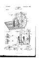
In describing the invention in detail reference is bad to the accompanying drawings, forming a part of this specification, wherein like numerals of reference indicate the corresponding parts throughout the several views thereof, and in which- Figure 1 is a perspective View of my improved churn as set upon a platform, a portion of the churn-body broken away, showing the position of the dasher and stationary screen. Fig. 2 is a side view thereof, the
body portion as well as a portion of the standard being in section. Fig. 3 is a side view, partly in section, of a portion of the operating-standard, showing the operating-shaft mounted therein. Fig. 4 is a front view of the hanger for the pulley-wheels, showing the same in difierent positions.
Referring to the drawings by reference-numerals, 1 indicates the platform upon which is mounted my improved churn and upon which is secured, as at 2, the supportingstandard for the operating mechanism. This supporting-standard consists of a hollow upright formed of two sections 3 and 4, secured together by the T-pipe 5, and the upper section 4 has suitably connected thereto the T- pipe 6.
Secured to the T-pipe 6 is an upper horizontal supporting-arm 7 and secured to the T- pipe 5 is a lower horizontal supporting-arm S. The arm 7 has connected to its free end the T- pipe 9, and the arm 8 the T-pipe 10. The T- pipes 9 and 10 are interiorly screw-threaded a portion of their inner face and are adapted to receive at this point the adjustable bearings 11 and 12 for the operating-shaft 14', which operates therethrough.
15 and 16 are stops or collars mounted on the shaft 14, stops l5 arresting the upward movement of the shaft and the stop 16 arresting the downward movement of the shaft as well as the'supporting-arm 8.
19 indicates a pulley-wheel which is secured to the shaft 14, between the stop or collar 15 and the collar 20. The pulley 19 is rigidly secured to the shaft and is adapted to be operated by the belt 21.
The lower end of the shaft 14 has an elon gated slot formed therein to allow of the upward movement of the securing-cap 22 for the dasher-shaft 23. This securing-cap is held to the shaft by means of a pin 24, operating through a portion of the cap and elongated slot. The cap 22 is held in positionby means of the adjustable spring 25, the one end of said spring abutting against the bearing 11 and the opposite end against the upper edge of the cap. It will be readily observed that when desired to place the dasher 23 in position all that will be necessary is to force the cap upward and insert the upper end of the shaft into the hollow portion of the cap. Owing to the adjusting-spring the cap will readily resume its normal position.
26 indicates the churn-body, which is or may be inclined as shown, having a vertical screen 27 mounted therein and the bearing 28 formed integral with the upper face of the bottom to receive the end of the dasher-shaft. Secured to the dasher-shaft by means of the set-screw 29 is the dasher, which consists of a hollow sleeve 30, with suitable perforations 31 arranged therein about midway thereof, and a series of perforations 32 arranged therein near the lower end thereof.
33 indicates a supporting-plate for the inclined blades 34:, which are secured to the underneath face thereofin any desirable manner. These blades overlap, as shown.
35 indicates a hanger having the extending arm 36 formed integral therewith, on which are mounted the pulley-wheels 37, between the guides or collars 38. These guides are adjustable and are secured to the extending arms bymeans of the set-screw 30, thereby making the pulley-wheels adjustable also.
Mounted upon the shaft 40 is the drivewheel 41, having a continuous groove 42 formed in its periphery to receive the operating-belt 21. The shaft 40 is secured in the upright or standard 3 by means of the nut 43 and projections or bearings 44, formed integral therewith.
45 indicates a suitable handle for operating the drive-wheel.
It will be observed that the extending arms 36 are bent at right angles to allow the positioning of the pulley-wheels in the desired manner.
It is thought that the operation of my improved churn can be readily understood by the foregoing desc1'iption,taken in connection with the accompanying drawings.
It will be noted that various changes may be made in the details of construction without departing from the general spirit of my invention.
, Having thus fully described my invention, what I claim as new, and desire to secure by Letters Patent, is-
A churn havinga vertical screen arranged therein mounted upon a suitable support, a tubular supporting-standard, a pair of horizontal arms each connected at their inner end by a T-shaped union to said tubular standard, a T-shaped union connected to the outer end of each of said horizontal arms, removable bearings arranged in the last-named T-shaped union,an operating-shaft journaled in the said bearings, and provided at its lower end with an elongated slot, avertically-movable cap connected to the said slotted end of the said operating-shaft, a spring arranged on said shaft for holding said cap normally at the lower end thereof, a pulley adj ustably mounted on the said shaft, adrive-wheel suitably connected to the said supporting-standard, a hanger secured to the upper end of the said supporting-standard, a pair of hangerarms formed integral with the said hanger, an adjustable pulley mounted on each of said hangerarms,a drive-belt engaging said drivewheel and the adjustable pulleys to operate the shaft when the drive-wheel is rotated thereby operating a suitable dasher arranged in the said churn, substantially as set forth.
In testimony whereof I affix my signature in the presence of tWo witnesses.
JAMES B. ODONNELL.
Vitnesses:
JOHN NOLAND, WILLIAM E. MINOR.
Priority Applications (1)
| Application Number | Priority Date | Filing Date | Title |
|---|---|---|---|
| US69417498A US636282A (en) | 1898-10-21 | 1898-10-21 | Churn. |
Applications Claiming Priority (1)
| Application Number | Priority Date | Filing Date | Title |
|---|---|---|---|
| US69417498A US636282A (en) | 1898-10-21 | 1898-10-21 | Churn. |
Publications (1)
| Publication Number | Publication Date |
|---|---|
| US636282A true US636282A (en) | 1899-11-07 |
Family
ID=2704872
Family Applications (1)
| Application Number | Title | Priority Date | Filing Date |
|---|---|---|---|
| US69417498A Expired - Lifetime US636282A (en) | 1898-10-21 | 1898-10-21 | Churn. |
Country Status (1)
| Country | Link |
|---|---|
| US (1) | US636282A (en) |
-
1898
- 1898-10-21 US US69417498A patent/US636282A/en not_active Expired - Lifetime
Similar Documents
| Publication | Publication Date | Title |
|---|---|---|
| US636282A (en) | Churn. | |
| US697152A (en) | Churn. | |
| US562296A (en) | Churn | |
| US838806A (en) | Churn. | |
| US111907A (en) | Improvement in churns | |
| US1100937A (en) | Churn. | |
| US1196612A (en) | Oscillating churn-dasher. | |
| US1007169A (en) | Churn. | |
| US391787A (en) | En-tqrs | |
| US495478A (en) | Churn | |
| US809031A (en) | Churn. | |
| US469702A (en) | Churn | |
| US428987A (en) | Churn-power | |
| US805710A (en) | Churn. | |
| US835126A (en) | Churn. | |
| US55491A (en) | Improvement in churns | |
| US567018A (en) | Churn | |
| US670298A (en) | Churn. | |
| US734535A (en) | Churn. | |
| US569925A (en) | Churn | |
| US1008241A (en) | Churn. | |
| US800244A (en) | Churn. | |
| US524071A (en) | Archibald mcmullan | |
| US816166A (en) | Churn. | |
| US7348A (en) | Workikg rotary and vebtical chubiw-dashees |