US6351097B1 - Manage system of rechargeable battery and a method for managing thereof - Google Patents
Manage system of rechargeable battery and a method for managing thereof Download PDFInfo
- Publication number
- US6351097B1 US6351097B1 US09/503,250 US50325000A US6351097B1 US 6351097 B1 US6351097 B1 US 6351097B1 US 50325000 A US50325000 A US 50325000A US 6351097 B1 US6351097 B1 US 6351097B1
- Authority
- US
- United States
- Prior art keywords
- cells
- batteries
- parallel
- mode
- rechargeable battery
- Prior art date
- Legal status (The legal status is an assumption and is not a legal conclusion. Google has not performed a legal analysis and makes no representation as to the accuracy of the status listed.)
- Expired - Fee Related
Links
- 238000000034 method Methods 0.000 title claims abstract description 41
- 238000007599 discharging Methods 0.000 claims description 52
- 230000000903 blocking effect Effects 0.000 claims description 7
- 239000004065 semiconductor Substances 0.000 claims description 3
- WHXSMMKQMYFTQS-UHFFFAOYSA-N Lithium Chemical compound [Li] WHXSMMKQMYFTQS-UHFFFAOYSA-N 0.000 description 3
- 229910003307 Ni-Cd Inorganic materials 0.000 description 3
- 229910052744 lithium Inorganic materials 0.000 description 3
- 229910001416 lithium ion Inorganic materials 0.000 description 3
- 229920000642 polymer Polymers 0.000 description 3
- XUIMIQQOPSSXEZ-UHFFFAOYSA-N Silicon Chemical compound [Si] XUIMIQQOPSSXEZ-UHFFFAOYSA-N 0.000 description 2
- OJIJEKBXJYRIBZ-UHFFFAOYSA-N cadmium nickel Chemical compound [Ni].[Cd] OJIJEKBXJYRIBZ-UHFFFAOYSA-N 0.000 description 2
- 238000010586 diagram Methods 0.000 description 2
- 230000009189 diving Effects 0.000 description 2
- 229910052710 silicon Inorganic materials 0.000 description 2
- 239000010703 silicon Substances 0.000 description 2
- HBBGRARXTFLTSG-UHFFFAOYSA-N Lithium ion Chemical compound [Li+] HBBGRARXTFLTSG-UHFFFAOYSA-N 0.000 description 1
- 239000002253 acid Substances 0.000 description 1
- 239000011149 active material Substances 0.000 description 1
- 229910052793 cadmium Inorganic materials 0.000 description 1
- BDOSMKKIYDKNTQ-UHFFFAOYSA-N cadmium atom Chemical compound [Cd] BDOSMKKIYDKNTQ-UHFFFAOYSA-N 0.000 description 1
- 238000007796 conventional method Methods 0.000 description 1
- 239000003792 electrolyte Substances 0.000 description 1
- 230000007613 environmental effect Effects 0.000 description 1
- 238000003912 environmental pollution Methods 0.000 description 1
- 230000005669 field effect Effects 0.000 description 1
- 230000006870 function Effects 0.000 description 1
- 230000003446 memory effect Effects 0.000 description 1
- 229910052987 metal hydride Inorganic materials 0.000 description 1
- 229910044991 metal oxide Inorganic materials 0.000 description 1
- 150000004706 metal oxides Chemical class 0.000 description 1
- 229910052759 nickel Inorganic materials 0.000 description 1
- PXHVJJICTQNCMI-UHFFFAOYSA-N nickel Substances [Ni] PXHVJJICTQNCMI-UHFFFAOYSA-N 0.000 description 1
- -1 nickel metal hydride Chemical class 0.000 description 1
- 230000001988 toxicity Effects 0.000 description 1
- 231100000419 toxicity Toxicity 0.000 description 1
- XLYOFNOQVPJJNP-UHFFFAOYSA-N water Substances O XLYOFNOQVPJJNP-UHFFFAOYSA-N 0.000 description 1
Images


Classifications
-
- H—ELECTRICITY
- H01—ELECTRIC ELEMENTS
- H01M—PROCESSES OR MEANS, e.g. BATTERIES, FOR THE DIRECT CONVERSION OF CHEMICAL ENERGY INTO ELECTRICAL ENERGY
- H01M10/00—Secondary cells; Manufacture thereof
- H01M10/42—Methods or arrangements for servicing or maintenance of secondary cells or secondary half-cells
- H01M10/44—Methods for charging or discharging
- H01M10/441—Methods for charging or discharging for several batteries or cells simultaneously or sequentially
-
- G—PHYSICS
- G01—MEASURING; TESTING
- G01R—MEASURING ELECTRIC VARIABLES; MEASURING MAGNETIC VARIABLES
- G01R31/00—Arrangements for testing electric properties; Arrangements for locating electric faults; Arrangements for electrical testing characterised by what is being tested not provided for elsewhere
- G01R31/36—Arrangements for testing, measuring or monitoring the electrical condition of accumulators or electric batteries, e.g. capacity or state of charge [SoC]
- G01R31/382—Arrangements for monitoring battery or accumulator variables, e.g. SoC
- G01R31/3835—Arrangements for monitoring battery or accumulator variables, e.g. SoC involving only voltage measurements
-
- H—ELECTRICITY
- H01—ELECTRIC ELEMENTS
- H01M—PROCESSES OR MEANS, e.g. BATTERIES, FOR THE DIRECT CONVERSION OF CHEMICAL ENERGY INTO ELECTRICAL ENERGY
- H01M10/00—Secondary cells; Manufacture thereof
- H01M10/42—Methods or arrangements for servicing or maintenance of secondary cells or secondary half-cells
- H01M10/44—Methods for charging or discharging
- H01M10/448—End of discharge regulating measures
-
- H—ELECTRICITY
- H01—ELECTRIC ELEMENTS
- H01M—PROCESSES OR MEANS, e.g. BATTERIES, FOR THE DIRECT CONVERSION OF CHEMICAL ENERGY INTO ELECTRICAL ENERGY
- H01M10/00—Secondary cells; Manufacture thereof
- H01M10/42—Methods or arrangements for servicing or maintenance of secondary cells or secondary half-cells
- H01M10/48—Accumulators combined with arrangements for measuring, testing or indicating the condition of cells, e.g. the level or density of the electrolyte
- H01M10/482—Accumulators combined with arrangements for measuring, testing or indicating the condition of cells, e.g. the level or density of the electrolyte for several batteries or cells simultaneously or sequentially
-
- H—ELECTRICITY
- H02—GENERATION; CONVERSION OR DISTRIBUTION OF ELECTRIC POWER
- H02J—CIRCUIT ARRANGEMENTS OR SYSTEMS FOR SUPPLYING OR DISTRIBUTING ELECTRIC POWER; SYSTEMS FOR STORING ELECTRIC ENERGY
- H02J7/00—Circuit arrangements for charging or depolarising batteries or for supplying loads from batteries
- H02J7/0013—Circuit arrangements for charging or depolarising batteries or for supplying loads from batteries acting upon several batteries simultaneously or sequentially
- H02J7/0024—Parallel/serial switching of connection of batteries to charge or load circuit
-
- H—ELECTRICITY
- H02—GENERATION; CONVERSION OR DISTRIBUTION OF ELECTRIC POWER
- H02J—CIRCUIT ARRANGEMENTS OR SYSTEMS FOR SUPPLYING OR DISTRIBUTING ELECTRIC POWER; SYSTEMS FOR STORING ELECTRIC ENERGY
- H02J7/00—Circuit arrangements for charging or depolarising batteries or for supplying loads from batteries
- H02J7/0063—Circuit arrangements for charging or depolarising batteries or for supplying loads from batteries with circuits adapted for supplying loads from the battery
-
- H—ELECTRICITY
- H02—GENERATION; CONVERSION OR DISTRIBUTION OF ELECTRIC POWER
- H02J—CIRCUIT ARRANGEMENTS OR SYSTEMS FOR SUPPLYING OR DISTRIBUTING ELECTRIC POWER; SYSTEMS FOR STORING ELECTRIC ENERGY
- H02J7/00—Circuit arrangements for charging or depolarising batteries or for supplying loads from batteries
- H02J7/007—Regulation of charging or discharging current or voltage
- H02J7/00712—Regulation of charging or discharging current or voltage the cycle being controlled or terminated in response to electric parameters
- H02J7/007182—Regulation of charging or discharging current or voltage the cycle being controlled or terminated in response to electric parameters in response to battery voltage
-
- Y—GENERAL TAGGING OF NEW TECHNOLOGICAL DEVELOPMENTS; GENERAL TAGGING OF CROSS-SECTIONAL TECHNOLOGIES SPANNING OVER SEVERAL SECTIONS OF THE IPC; TECHNICAL SUBJECTS COVERED BY FORMER USPC CROSS-REFERENCE ART COLLECTIONS [XRACs] AND DIGESTS
- Y02—TECHNOLOGIES OR APPLICATIONS FOR MITIGATION OR ADAPTATION AGAINST CLIMATE CHANGE
- Y02E—REDUCTION OF GREENHOUSE GAS [GHG] EMISSIONS, RELATED TO ENERGY GENERATION, TRANSMISSION OR DISTRIBUTION
- Y02E60/00—Enabling technologies; Technologies with a potential or indirect contribution to GHG emissions mitigation
- Y02E60/10—Energy storage using batteries
Definitions
- the present invention relates to a system to recharge batteries (or secondary cell, storage battery) and a method for managing the system. More specifically, the present invention relates to a system and a method for managing rechargeable batteries which are used in various portable electrical equipment such as a wireless radio, an audio tape player, a camera, an electric lamp and so on.
- the termination voltage is equalized using parallel discharging method before charging the rechargeable battery so that the durability of the rechargeable battery is expanded and the efficiency of the charging is enhanced.
- the rechargeable battery so called a secondary battery, or a storage battery is produced and sold in various types and sizes.
- the typical types of the rechargeable battery includes a nickel cadmium (NiCd) type, a lead-acid type, a nickel metal hydride (NiMH) type, a lithium ion (Li-ion) type, a lithium polymer type, an alkaline type and so on.
- These rechargeable batteries should be charged using the appropriate charging method in order that they may be used to their full extent.
- the NiCd type is preferred to be fully discharged periodically.
- the Li-ion type used in notebook computers video cameras, mobile telephones and so on, is preferred to be charged before it is discharged up to the discharge terminal voltage.
- the lithium polymer type used in the small electrical devices, the medical equipment, computers and so on, should be always in a charged state before it is exhausted by discharge. The durability of the lithium polymer type could be shortened, if it is fully discharged like nickel cadmium type.
- Ni—Cd and NiMH type chargeable batteries Because the Ni—Cd type costs less and is easy to store and deliver as well as being rechargeable in a short time, it is still used in many fields.
- the rechargeable battery in the industrial field because the discharging energy per time is large, it is durable and it can be repeatedly recharged others. It is applied to electrical devices which need significant amount electrical energy such as a flash of a camera, a cordless telephone, a radio, a satellite auxiliary battery, a motor driver, a portable and wireless vacuum cleaner, a diving light, a radio controlled model (car, airplane and ship) and so on.
- the Ni-type battery is recharged without deep discharging, the rechargeable capacitance is reduced due to memory effect of crystalizing the un-reacted active materials.
- the rechargeable batteries are used in serial connection with many cells except for the case of using only one cell.
- the cells are discharged so that they are in a different energy state.
- the energy state of the cells also become different if they are recharged. If a group of the cells are discharged and recharged many times, then the termination voltage of some cells could be lower than 0.1 volt. In this state, if the user further uses these cells, then the electrical potential is reversed so that these cells are in the battery reversal state.
- the secondary battery which comprises many rechargeable cells having different energy states are connected serially are recharged, then the recharging is stopped when one cell having the most high energy state sends the termination signal to the charger stopping the charge despite that other cells are not charged yet.
- the other cells reach over charged state before the over discharged cell is completely charged. That is, the status of some cells comprised in the secondary battery moves back and forth between the uncompleted charging state and the over discharging (or battery reversal) state. At the same time, the status of the other cells move back and forth between the completed charging state and the uncompleted discharging state. Therefore, all the cells are damaged.
- the performance of the Ni-type rechargeable battery can be enhanced by deep discharging periodically so that the crystallized electrolytes are removed.
- the secondary battery generally comprises many cells connected in serial in order to obtain the desired electric voltage for using in the electrical device. Under this state, if one the secondary battery cell is discharged for management, then other cells of the secondary battery can be over discharged or be in the battery reversal state. That is, it is hard to recover or to equalize the cells using the discharging method in the serial connection.
- the individual discharging method is suggested in the U.S. Pat. No. 3,980,940, as shown in FIG. 1 .
- This conventional invention suggests a method for managing the secondary battery in which the cells are equalized by deep discharging individually before they are recharged in serial connection.
- the rechargeable batteries (cells) 1 a , 1 b , 1 c and, 1 d are connected in serial connection.
- the recharging means 11 is connected to the rechargeable batteries 1 a to 1 d .
- the discharging means 21 comprising the electrical load means 23 a , 23 b , 23 c and 23 d and discharging blocking switch 25 a , 25 b , 25 c and, 25 d is connected with the rechargeable batteries 1 a to 1 d individually. That is, the electrical load means 23 a to 23 d and the discharging blocking switch 25 a to 25 d are connected to the rechargeable batteries 1 a to 1 d , respectively.
- each cell 1 a to 1 d is discharged individually using the discharging means 21 after the cells are recharged in serial connection using the recharging means 11 .
- the amount of the energy wastes during individual discharging is very big and it takes a long time to discharge all the cells in different energy state should be fully discharged.
- One object of the present invention is to provide a system and a method for managing the rechargeable batteries in which they are protected from the being damaged due to over discharge or over charge by equalizing the energy difference of the each rechargeable battery.
- Another object of the present invention is to provide a system and a method for managing the chargeable batteries in which the rechargeable batteries are discharged in parallel connection for equalizing the energy states of the each battery and then they are recharged in serial connection, so that the discharging efficiency is maximized and the charging is performed quickly.
- the present invention provides a managing system for rechargeable battery comprising a plurality of a rechargeable unit batteries, a closed loop circuit method which connects the cells in parallel connection electrically, an electrical load having regular voltage which is the sum of the maximum output voltage among the plurality of cells and being in parallel connection with the rechargeable cells which are connected in parallel with the closed loop circuit method, a rechargeable battery manager including a discharging blocking switch inserted between the plurality of cells and the electrical load means in order to cut off the current flowing in the electrical load means in case it reaches the discharge termination voltage of the plurality of rechargeable cells.
- the present invention provides a method of managing the rechargeable battery including a step of discharging for a certain time period by parallel connecting the plurality of rechargeable cells which have different energy level using the battery manager for discharging.
- the present invention also provides a plurality of rechargeable cells, a closed loop circuit means connecting the rechargeable cells, a selection switch connected to the closed loop circuit means which allows the cells to be connected either by parallel connection or serial connection, an electrical load having regular voltage which is the sum of the maximum output voltage among the plurality of cells and being in parallel connection with the rechargeable cells which are connected in parallel with the closed loop circuit method and a manager for rechargeable battery including a voltage applying means which provides rechargeable voltage between the both electrodes of the cells connected in the serial connection in case the cells are in serial connection at the same time the current flowing in the electrical load means is cut off by the switch means.
- the present invention provides a managing method for rechargeable batteries including steps of discharging the plurality of rechargeable cells which have different energy level for a certain time period by connecting them in parallel connection using the manager for chargeable cells and charging the plurality of the rechargeable cells by connecting them in serial connection after the above mentioned parallel discharge.
- FIG. 1 is a illustration showing a method and a system of recharging the rechargeable battery individually after fully discharging by using the conventional method of individual discharging method.
- FIG. 2 a is an illustration showing a method and a system of managing the rechargeable batteries by parallel discharging according to the present invention.
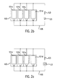
- FIG. 2 b is an illustration showing a method and a system of managing the rechargeable batteries by parallel discharging using a diode switch to block over discharging.
- FIG. 2 c is an illustration showing a method and a system of managing the rechargeable batteries by parallel discharging using a timer to block over discharging.
- FIG. 3 is a block diagram showing the main concept of the present invention which suggests a method and a system of managing the rechargeable batteries by parallel discharging and serial recharging.
- FIG. 4 is a close loop circuit diagram of the present invention.
- FIG. 5 a is an illustration showing circuit in which the cells are connected in parallel by the switch operation.
- FIG. 5 b is an illustration showing circuit in which the cells are connected in serial by the switch operation.
- FIG. 6 is an illustration showing the operation condition of the battery managing device according to the present invention.
- FIG. 2 a is a view showing a manager for the rechargeable battery system according to a first embodiment of the present invention. It shows the core scope of the present invention which is the managing module and the managing method thereof in order to have equalization of the rechargeable battery by the parallel connection.
- a rechargeable battery in other words, a secondary battery, comprising at least one or more cells to be one group, is described.
- the secondary battery connects two, three, four, five, six, eight or ten cells in serial connection and is used to obtain the suitable electromotive force for the device to be used.
- a case of using four cells 101 a , 101 b , 101 c and 101 d which are used commonly in digital camera, a flash of camera, under water diving flash lights and toys is described.
- at least one of the cells 101 a , 101 b , 101 c and 101 d reaches the discharge termination voltage when the secondary battery is applied to a device, it needs to be recharged.
- the cells After separating the cells 101 a , 101 b , 101 c and 101 d from the devices, the cells are reconnected in parallel. Then, an electrical load 123 having the regular voltage corresponding to the electromotive force of a cell is connected in parallel with the cells 101 a , 101 b , 101 c and 101 d . As a result, each of the cells 101 a , 101 b , 101 c and 101 d comprising the secondary battery discharges simultaneously.
- the cells 101 a , 101 b , 101 c and 101 d may start with different voltage states, but are equalized after the parallel discharge. After each of the cells are equalized by carrying out the parallel discharge for a certain period of time, the cells are charge by connecting to the serial charging circuit.
- Time consumed in managing the chargeable battery by using parallel discharge can differ according to the condition of each cell. It is usually preferred to take the time consumed until the reaching the discharge termination voltage of the secondary battery connected in parallel as the managing time. Therefore, a silicon diode 125 having minimum through voltage (threshold voltage) corresponding to the sum of the discharge termination voltage of the secondary battery can be used by connecting it with the cells 101 a , 101 b , 101 c and 101 d in parallel as shown in FIG. 2 b.
- a timer 127 is installed in order to control the discharging time artificially as shown in FIG. 2 c .
- effective management can be obtained by discharging 3 to 5 minutes when the discharge ratio is 1C to 2C (1C means charging or discharging its capacitance in an hour).
- the rechargeable battery of the present invention basically includes the following elements: battery holders 103 a , 103 b , 103 c and 103 d which electrically connect the cells 101 a , 101 b , 101 c and 101 d , in other words, the plurality of rechargeable battery in order to carry out the managing method of the rechargeable battery.
- the cells 101 a , 101 b , 101 c and 101 d can be used in a serial connection so that they suit electromotive force of the electrical device being used.
- a closed loop circuit 105 which connect the cells 101 a , 101 b , 101 c and 101 d in parallel connection is included.
- a device like resistance, bulb and electrical motor which can consume regular voltage corresponding to the electromotive force of the cell is used.
- a discharging blocking switch 125 which is in serial connection with the electrical load 123 and in parallel connection with cells 101 a , 101 b , 101 c and 101 d , prevents further discharge when the parallel connected cells 101 a , 101 b , 101 c and 101 d start discharging and finish discharging when it reaches the discharge termination voltage. It is preferable to use silicon diode having the minimum through voltage (threshold voltage) corresponding to the discharge termination voltage (in other words, the sum of parallel connection of the discharge termination voltage of each of the cells) of the secondary battery for the discharging blocking switch 125 .
- the preferred embodiment 1 illustrates the managing device and the managing method thereof in order to carry out parallel discharge of the rechargeable cells comprising the secondary battery for the purpose of equalization before recharging.
- a managing device for the rechargeable battery which includes the charging function and the managing method thereof is illustrated.
- the FIG. 3 is a view showing the basic concept structure of a managing device for the rechargeable battery according to this preferred embodiment.
- a rechargeable battery 101 comprising one or more cells as one group is needed.
- the chargeable battery 101 is connected to a closed loop circuit 105 which has a switch 107 that can choose between serial connection and parallel connection.
- the selection switch 107 is connected to a battery condition tester 109 as the selection whether it is parallel or serial is determined by the voltage condition of the chargeable batteries 101 . If the rechargeable batteries 101 are parallel connected by the selection switch 107 , make the rechargeable battery to be connected with a discharger 123 having the regular voltage which corresponds to the electromotive force of one cell between the both terminals of the batteries 101 .
- a timer 127 which can send signal to change the connection of the rechargeable batteries 101 into serial connection after the discharging has been carried out for a certain period of time, may be connected between the selection switch 107 and the discharging means 123 . After the parallel discharge is carried out for a certain period of time by the signal of the timer 127 , a charger 111 for recharging the chargeable batteries 101 after transferring into a serial connection by the selection switch 107 is connected to the closed loop circuit 105 .
- a secondary battery comprising one or more cell as one group is needed.
- the secondary battery connects two, three, or more cells serially in order to obtain an acceptable electromotive force suitable for the device to be used.
- usage of four cells is introduced again as an example for it is used mostly commonly.
- Battery holders 103 a , 103 b , 103 c and 103 d hold cells 101 a , 101 b , 101 c and 101 d .
- a closed loop circuit 105 which allows the cells 101 a , 101 b , 101 c and 101 d to be connected in parallel or in serial by using the conductive wire, like an electric wire is connected to the battery holder 103 a , 103 b , 103 c and 103 d.
- a selection switch 107 which chooses either a serial connection or a parallel connection for the cells 101 a , 101 b , 101 c and 101 d is included in the closed loop circuit 105 .
- the selection switch 107 can be selected among a rotary switch, relay or a semiconductor element like MOSFET (Metal Oxide Semiconductor Field Effect Transistor).
- Both terminals of the cells 101 a , 101 b , 101 c and 101 d are connected to the charger 111 if the cells 101 a , 101 b , 101 c and 101 d are connected in serial connection and both terminals of the cells 101 a , 101 b , 101 c and 101 d are connected to the charger 123 if the cells 101 a , 101 b , 101 c and 101 d are connected in parallel connection according to the connection of the selection switch 107 .
- FIG. 4 is a view showing an example of closed loop circuit 105 which is structured to connect either by serial connection or parallel connection.
- FIG. 5 a shows a circuit when the cells are serially connected by the switch operation and
- FIG. 5 b shows a circuit when the cells are parallely connected by the switch operation.
- FIG. 6 is a view showing the operation condition of the battery managing device according to the present invention.
- the closed loop circuit 105 connects the cells 101 a , 101 b , 101 c and 101 d serially in the initial stage 6 a as shown in FIG. 6 .
- the time consumed in parallel discharge is automatically set up by a timer 127 which is installed between the 123 and the selection switch 107 . It is preferred that the time for discharging is set up to be within 5 minutes as shown in state 6 e of FIG. 6 .
- the connection of the cells 101 a , 101 b , 101 c and 101 d are changed into a serial connection as shown in state 6 f of FIG. 6 .
- the cells 101 a , 101 b , 101 c and 101 d are connected to the charging means 111 in serial connection and recharging is carried out as shown in state 6 g of FIG. 6 .
- the electromotive force is monitored while charging and if it is same or higher than the using voltage as shown in stage 6 b of FIG. 6, charging is ceased and goes into a waiting mode as shown in stage 6 h of FIG. 6 .
- the present invention provides the managing device for chargeable battery which charges by connecting the same kinds of chargeable batteries in serial connection after carrying out in discharging the parallel connection.
- high speed charging is possible as the chargeable battery is recharged after equalizing the battery cells through parallel discharge. Also, over charged and over discharged rechargeable battery which were thought to be destroyed are recycled during the process of equalization through the parallel discharge.
Landscapes
- Engineering & Computer Science (AREA)
- Power Engineering (AREA)
- Manufacturing & Machinery (AREA)
- Chemical & Material Sciences (AREA)
- Chemical Kinetics & Catalysis (AREA)
- Electrochemistry (AREA)
- General Chemical & Material Sciences (AREA)
- Physics & Mathematics (AREA)
- General Physics & Mathematics (AREA)
- Charge And Discharge Circuits For Batteries Or The Like (AREA)
- Secondary Cells (AREA)
Priority Applications (1)
| Application Number | Priority Date | Filing Date | Title |
|---|---|---|---|
| US09/635,688 US6337555B1 (en) | 1999-02-12 | 2000-08-10 | Manage system of rechargeable battery and a method for managing thereof |
Applications Claiming Priority (2)
| Application Number | Priority Date | Filing Date | Title |
|---|---|---|---|
| KR19990005042 | 1999-02-12 | ||
| KR99-5042 | 1999-02-12 |
Related Child Applications (1)
| Application Number | Title | Priority Date | Filing Date |
|---|---|---|---|
| US09/635,688 Continuation-In-Part US6337555B1 (en) | 1999-02-12 | 2000-08-10 | Manage system of rechargeable battery and a method for managing thereof |
Publications (1)
| Publication Number | Publication Date |
|---|---|
| US6351097B1 true US6351097B1 (en) | 2002-02-26 |
Family
ID=19574247
Family Applications (1)
| Application Number | Title | Priority Date | Filing Date |
|---|---|---|---|
| US09/503,250 Expired - Fee Related US6351097B1 (en) | 1999-02-12 | 2000-02-14 | Manage system of rechargeable battery and a method for managing thereof |
Country Status (8)
| Country | Link |
|---|---|
| US (1) | US6351097B1 (enExample) |
| JP (1) | JP2000232738A (enExample) |
| KR (1) | KR20000057966A (enExample) |
| CN (1) | CN1146066C (enExample) |
| AU (1) | AU1639000A (enExample) |
| DE (1) | DE10006420A1 (enExample) |
| FR (1) | FR2789819B1 (enExample) |
| GB (1) | GB2348748B (enExample) |
Cited By (15)
| Publication number | Priority date | Publication date | Assignee | Title |
|---|---|---|---|---|
| US20040135546A1 (en) * | 2002-11-25 | 2004-07-15 | Tiax, Llc | System and method for balancing state of charge among series-connected electrical energy storage units |
| US20050029986A1 (en) * | 2000-03-06 | 2005-02-10 | Richard Morgan | Rechargeable batteries |
| US20080259551A1 (en) * | 2007-04-20 | 2008-10-23 | Gotive A.S. | Modular computing device |
| US20100149706A1 (en) * | 2008-12-11 | 2010-06-17 | Stl Technology Co., Ltd. | Removable and short-circuit-avoidable lithium battery module |
| FR2947112A1 (fr) * | 2009-10-29 | 2010-12-24 | Commissariat Energie Atomique | Dispositif de recharge d'une batterie d'accumulateurs |
| US20120205984A1 (en) * | 2009-10-30 | 2012-08-16 | Makita Corporation | Power supply device |
| CN103683911A (zh) * | 2012-09-03 | 2014-03-26 | 卡西欧计算机株式会社 | 充电装置及充电方法 |
| US9293935B2 (en) | 2010-11-02 | 2016-03-22 | Navitas Solutions, Inc. | Wireless battery area network for a smart battery management system |
| US9559530B2 (en) | 2010-11-02 | 2017-01-31 | Navitas Solutions | Fault tolerant wireless battery area network for a smart battery management system |
| US9564762B2 (en) | 2010-11-02 | 2017-02-07 | Navitas Solutions | Fault tolerant wireless battery area network for a smart battery management system |
| US20170163053A1 (en) * | 2011-10-12 | 2017-06-08 | Mechanical Energy Generating Systems, L.L.C. | Systems, methods, and apparatus for a homopolar generator charger with integral rechargeable battery |
| US9800719B1 (en) * | 2017-07-11 | 2017-10-24 | Premergy, Inc. | Systems and methods for managing power for a mobile device |
| US20190344682A1 (en) * | 2017-01-25 | 2019-11-14 | Huawei Technologies Co., Ltd. | Charging Pile System |
| US10870367B2 (en) | 2016-04-28 | 2020-12-22 | Bayerische Motoren Werke Aktiengesellschaft | Switchable storage system for a vehicle |
| US20220344732A1 (en) * | 2017-10-18 | 2022-10-27 | Textron Innovations, Inc. | Internal battery heating |
Families Citing this family (19)
| Publication number | Priority date | Publication date | Assignee | Title |
|---|---|---|---|---|
| GB2360148A (en) * | 2000-03-06 | 2001-09-12 | Richard Thomas Morgan | Individual charging of cells in a rechargeable battery |
| KR100459991B1 (ko) * | 2002-04-10 | 2004-12-04 | 오우석 | 충전용 배터리 관리기 |
| KR100451637B1 (ko) * | 2002-06-18 | 2004-10-08 | 오세광 | 충전용 배터리 관리기 |
| KR100569016B1 (ko) * | 2004-03-11 | 2006-04-07 | 현대자동차주식회사 | 하이브리드형 에너지 저장장치의 전압 균형 제어장치 |
| KR101220339B1 (ko) | 2007-10-16 | 2013-01-09 | 한국과학기술원 | 직렬연결 배터리 스트링을 위한 자동 전하 균일 방법 및장치 |
| KR101107999B1 (ko) | 2007-10-16 | 2012-01-25 | 한국과학기술원 | 전압 센서와 전하 균일 장치가 결합된 배터리 운용 시스템 |
| KR101164629B1 (ko) | 2007-10-16 | 2012-07-11 | 한국과학기술원 | 직렬 연결 배터리 스트링을 위한 2단 전하 균일 방법 및장치 |
| CN101593854B (zh) * | 2008-05-26 | 2011-07-27 | 台湾神户电池股份有限公司 | 电池充放电装置 |
| CN102201690A (zh) * | 2011-05-18 | 2011-09-28 | 肇庆理士电源技术有限公司 | 一种充放电机的扩展使用方法 |
| CN102738430A (zh) * | 2012-05-09 | 2012-10-17 | 刘跨云 | 快充式蓄电池 |
| JP2013240219A (ja) * | 2012-05-16 | 2013-11-28 | Sharp Corp | 蓄電池システムおよび蓄電池システム構築方法 |
| JP5660105B2 (ja) * | 2012-10-24 | 2015-01-28 | トヨタ自動車株式会社 | 蓄電システム |
| JP5611400B2 (ja) * | 2013-03-27 | 2014-10-22 | 三菱重工業株式会社 | 産業機械用電池システム |
| CA2900271A1 (en) * | 2014-08-21 | 2016-02-21 | Johnson & Johnson Vision Care, Inc. | Components with multiple energization elements for biomedical devices |
| CN104578310A (zh) * | 2015-01-23 | 2015-04-29 | 深圳市沃特玛电池有限公司 | 电池组能量均衡电路 |
| CN105978049A (zh) * | 2015-10-26 | 2016-09-28 | 乐视移动智能信息技术(北京)有限公司 | 电池倍压充电电路和移动终端 |
| DE102016224005A1 (de) * | 2016-12-02 | 2018-06-07 | Audi Ag | Elektrische Energiespeichereinrichtung |
| FR3067861B1 (fr) * | 2017-06-14 | 2021-12-17 | Peugeot Citroen Automobiles Sa | Batterie pour vehicule hybride ou electrique comportant des commutateurs pour une adaptation a un chargeur |
| DE102021210037B4 (de) | 2021-09-10 | 2025-10-23 | Volkswagen Aktiengesellschaft | Verfahren zum Betrieb einer wiederaufladbaren, lithiumhaltigen und/oder natriumhaltigen Batterie |
Citations (3)
| Publication number | Priority date | Publication date | Assignee | Title |
|---|---|---|---|---|
| US3980940A (en) | 1973-04-10 | 1976-09-14 | Mabuchi Motor Co. Ltd. | Battery equalizing system |
| US5356343A (en) * | 1992-07-29 | 1994-10-18 | Lovetere Christopher J | Flash magic wand |
| US5760570A (en) * | 1995-11-10 | 1998-06-02 | Sony Corporation | Rechargeable battery apparatus |
Family Cites Families (9)
| Publication number | Priority date | Publication date | Assignee | Title |
|---|---|---|---|---|
| GB1428661A (en) * | 1972-03-15 | 1976-03-17 | Varta Great Britain Ltd | Stand-by electric power supply units |
| CH608661A5 (en) * | 1977-04-01 | 1979-01-15 | Leclanche Sa | Device comprising a number N of electric accumulators of like voltage and like capacitance |
| US4303877A (en) * | 1978-05-05 | 1981-12-01 | Brown, Boveri & Cie Aktiengesellschaft | Circuit for protecting storage cells |
| EP0593770B1 (en) * | 1992-03-16 | 1997-10-08 | 4C Technologies Inc. | Quick charger and quick charge method for nickel-cadmium battery |
| JPH07212980A (ja) * | 1994-01-13 | 1995-08-11 | Fujitsu Ltd | バッテリの充・放電装置 |
| JPH08340641A (ja) * | 1995-06-12 | 1996-12-24 | Tokyo R & D:Kk | 電池電源回路 |
| KR0137758Y1 (ko) * | 1995-11-16 | 1999-05-15 | 한승준 | 전기자동차의 배터리 과충전 방지장치 |
| GB2358300B (en) * | 1997-02-10 | 2001-08-29 | Nec Corp | Portable electronic device and battery pack |
| US6057670A (en) * | 1998-11-04 | 2000-05-02 | Saft America, Inc. | Smart connector for rechargeable battery |
-
2000
- 2000-02-08 KR KR1020000005820A patent/KR20000057966A/ko active Granted
- 2000-02-11 GB GB0003253A patent/GB2348748B/en not_active Expired - Fee Related
- 2000-02-11 FR FR0001763A patent/FR2789819B1/fr not_active Expired - Fee Related
- 2000-02-12 CN CNB00100784XA patent/CN1146066C/zh not_active Expired - Fee Related
- 2000-02-14 AU AU16390/00A patent/AU1639000A/en not_active Abandoned
- 2000-02-14 US US09/503,250 patent/US6351097B1/en not_active Expired - Fee Related
- 2000-02-14 JP JP2000035554A patent/JP2000232738A/ja active Pending
- 2000-02-14 DE DE10006420A patent/DE10006420A1/de not_active Withdrawn
Patent Citations (3)
| Publication number | Priority date | Publication date | Assignee | Title |
|---|---|---|---|---|
| US3980940A (en) | 1973-04-10 | 1976-09-14 | Mabuchi Motor Co. Ltd. | Battery equalizing system |
| US5356343A (en) * | 1992-07-29 | 1994-10-18 | Lovetere Christopher J | Flash magic wand |
| US5760570A (en) * | 1995-11-10 | 1998-06-02 | Sony Corporation | Rechargeable battery apparatus |
Cited By (29)
| Publication number | Priority date | Publication date | Assignee | Title |
|---|---|---|---|---|
| US20050029986A1 (en) * | 2000-03-06 | 2005-02-10 | Richard Morgan | Rechargeable batteries |
| US7459882B2 (en) * | 2000-03-06 | 2008-12-02 | Richard Morgan | Rechargeable batteries |
| US20040135546A1 (en) * | 2002-11-25 | 2004-07-15 | Tiax, Llc | System and method for balancing state of charge among series-connected electrical energy storage units |
| US20040135545A1 (en) * | 2002-11-25 | 2004-07-15 | Tiax, Llc | Bidirectional power converter for balancing state of charge among series connected electrical energy storage units |
| US7193392B2 (en) | 2002-11-25 | 2007-03-20 | Tiax Llc | System and method for determining and balancing state of charge among series connected electrical energy storage units |
| US7245108B2 (en) | 2002-11-25 | 2007-07-17 | Tiax Llc | System and method for balancing state of charge among series-connected electrical energy storage units |
| US7378818B2 (en) | 2002-11-25 | 2008-05-27 | Tiax Llc | Bidirectional power converter for balancing state of charge among series connected electrical energy storage units |
| US20080191663A1 (en) * | 2002-11-25 | 2008-08-14 | Tiax Llc | Bidirectional power converter for balancing state of charge among series connected electrical energy storage units |
| US20080259551A1 (en) * | 2007-04-20 | 2008-10-23 | Gotive A.S. | Modular computing device |
| US20100149706A1 (en) * | 2008-12-11 | 2010-06-17 | Stl Technology Co., Ltd. | Removable and short-circuit-avoidable lithium battery module |
| US8119275B2 (en) * | 2008-12-11 | 2012-02-21 | Stl Technology Co., Ltd. | Removable and short-circuit-avoidable lithium battery module |
| FR2947112A1 (fr) * | 2009-10-29 | 2010-12-24 | Commissariat Energie Atomique | Dispositif de recharge d'une batterie d'accumulateurs |
| US9112360B2 (en) * | 2009-10-30 | 2015-08-18 | Makita Corporation | Power supply device |
| US20120205984A1 (en) * | 2009-10-30 | 2012-08-16 | Makita Corporation | Power supply device |
| US9293935B2 (en) | 2010-11-02 | 2016-03-22 | Navitas Solutions, Inc. | Wireless battery area network for a smart battery management system |
| US9559530B2 (en) | 2010-11-02 | 2017-01-31 | Navitas Solutions | Fault tolerant wireless battery area network for a smart battery management system |
| US9564762B2 (en) | 2010-11-02 | 2017-02-07 | Navitas Solutions | Fault tolerant wireless battery area network for a smart battery management system |
| US20170163053A1 (en) * | 2011-10-12 | 2017-06-08 | Mechanical Energy Generating Systems, L.L.C. | Systems, methods, and apparatus for a homopolar generator charger with integral rechargeable battery |
| US12046935B2 (en) | 2011-10-12 | 2024-07-23 | Premergy, Inc. | Systems and methods for battery impedance matching to facilitate improved battery charging |
| US11322952B2 (en) | 2011-10-12 | 2022-05-03 | Premergy, Inc. | Systems and methods for battery impedance matching to facilitate improved battery charging |
| US10673257B2 (en) * | 2011-10-12 | 2020-06-02 | Premergy, Inc. | Systems and methods for battery impendance matching to facilitate improved battery charging |
| CN103683911B (zh) * | 2012-09-03 | 2016-03-16 | 卡西欧计算机株式会社 | 充电装置及充电方法 |
| CN103683911A (zh) * | 2012-09-03 | 2014-03-26 | 卡西欧计算机株式会社 | 充电装置及充电方法 |
| US10870367B2 (en) | 2016-04-28 | 2020-12-22 | Bayerische Motoren Werke Aktiengesellschaft | Switchable storage system for a vehicle |
| US10919403B2 (en) * | 2017-01-25 | 2021-02-16 | Huawei Technologies Co., Ltd. | Charging pile system with a plurality of charging piles switchable in series and parallel |
| US20190344682A1 (en) * | 2017-01-25 | 2019-11-14 | Huawei Technologies Co., Ltd. | Charging Pile System |
| US10142460B1 (en) * | 2017-07-11 | 2018-11-27 | Premergy, Inc. | Systems and methods for managing power for a mobile device |
| US9800719B1 (en) * | 2017-07-11 | 2017-10-24 | Premergy, Inc. | Systems and methods for managing power for a mobile device |
| US20220344732A1 (en) * | 2017-10-18 | 2022-10-27 | Textron Innovations, Inc. | Internal battery heating |
Also Published As
| Publication number | Publication date |
|---|---|
| KR100339119B1 (enExample) | 2002-05-31 |
| JP2000232738A (ja) | 2000-08-22 |
| GB2348748B (en) | 2003-09-24 |
| FR2789819A1 (fr) | 2000-08-18 |
| AU1639000A (en) | 2000-08-24 |
| FR2789819B1 (fr) | 2002-09-27 |
| GB2348748A (en) | 2000-10-11 |
| KR20000057966A (ko) | 2000-09-25 |
| CN1146066C (zh) | 2004-04-14 |
| HK1028844A1 (en) | 2001-03-02 |
| CN1263364A (zh) | 2000-08-16 |
| DE10006420A1 (de) | 2000-08-31 |
| GB0003253D0 (en) | 2000-04-05 |
Similar Documents
| Publication | Publication Date | Title |
|---|---|---|
| US6351097B1 (en) | Manage system of rechargeable battery and a method for managing thereof | |
| US11050281B2 (en) | Systems and methods for enhancing the performance and utilization of battery systems | |
| US9966780B2 (en) | Extended life battery | |
| KR940003003B1 (ko) | 배터리 어셈블리 및 배터리 어셈블리 충전 시스템 | |
| CN107615613B (zh) | 电池组管理装置和方法 | |
| US3930192A (en) | Stand-by power system | |
| JP2002142377A (ja) | 再充電可能バッテリ用インテリジェントパワー管理 | |
| US20040189250A1 (en) | Rechargeable battery, and apparatus and method of charging the same | |
| JP2003157908A (ja) | リチウムイオン二次電池充電装置および方法 | |
| WO2009128080A1 (en) | Method and apparatus for rapidly charging a battery | |
| KR101177455B1 (ko) | 배터리 충전 장치, 배터리 팩, 배터리 충전 시스템 및 그충전 방법 | |
| JP2000150001A (ja) | 充電式電池用のスマ―トコネクタ | |
| US6337555B1 (en) | Manage system of rechargeable battery and a method for managing thereof | |
| JPH0956056A (ja) | 二次電池電源装置および保護回路ならびに異常充電保護方法 | |
| US5462814A (en) | Method and apparatus for providing an electronic lockout for a rechargeable battery | |
| US6265847B1 (en) | Rechargeable battery control device | |
| JP2000253586A (ja) | 電池の充電方法と電源装置 | |
| JP3829441B2 (ja) | 2次電池の制御装置、2次電池の制御装置を備えた電池パック及び2次電池の制御方法 | |
| KR100459991B1 (ko) | 충전용 배터리 관리기 | |
| TW523947B (en) | A manage system of rechargeable battery and a method for managing thereof | |
| JPH11185824A (ja) | 一次電池互換バッテリーパック | |
| KR200211543Y1 (ko) | 배터리 관리기 | |
| HK1028844B (en) | A manage system of rechargeable battery and a method for managing thereof | |
| Prasad et al. | Development of charge equalization circuit | |
| KR200274637Y1 (ko) | 전압변환 및 방전기능이 구비된 휴대용 멀티 배터리팩 |
Legal Events
| Date | Code | Title | Description |
|---|---|---|---|
| REMI | Maintenance fee reminder mailed | ||
| LAPS | Lapse for failure to pay maintenance fees | ||
| STCH | Information on status: patent discontinuation |
Free format text: PATENT EXPIRED DUE TO NONPAYMENT OF MAINTENANCE FEES UNDER 37 CFR 1.362 |
|
| FP | Lapsed due to failure to pay maintenance fee |
Effective date: 20060226 |