US633014A - Motor-vehicle. - Google Patents
Motor-vehicle. Download PDFInfo
- Publication number
- US633014A US633014A US71082099A US1899710820A US633014A US 633014 A US633014 A US 633014A US 71082099 A US71082099 A US 71082099A US 1899710820 A US1899710820 A US 1899710820A US 633014 A US633014 A US 633014A
- Authority
- US
- United States
- Prior art keywords
- motor
- wheel
- lever
- shaft
- hub
- Prior art date
- Legal status (The legal status is an assumption and is not a legal conclusion. Google has not performed a legal analysis and makes no representation as to the accuracy of the status listed.)
- Expired - Lifetime
Links
Images


Classifications
-
- F—MECHANICAL ENGINEERING; LIGHTING; HEATING; WEAPONS; BLASTING
- F16—ENGINEERING ELEMENTS AND UNITS; GENERAL MEASURES FOR PRODUCING AND MAINTAINING EFFECTIVE FUNCTIONING OF MACHINES OR INSTALLATIONS; THERMAL INSULATION IN GENERAL
- F16H—GEARING
- F16H61/00—Control functions within control units of change-speed- or reversing-gearings for conveying rotary motion ; Control of exclusively fluid gearing, friction gearing, gearings with endless flexible members or other particular types of gearing
- F16H61/02—Control functions within control units of change-speed- or reversing-gearings for conveying rotary motion ; Control of exclusively fluid gearing, friction gearing, gearings with endless flexible members or other particular types of gearing characterised by the signals used
- F16H61/0293—Control functions within control units of change-speed- or reversing-gearings for conveying rotary motion ; Control of exclusively fluid gearing, friction gearing, gearings with endless flexible members or other particular types of gearing characterised by the signals used the signals being purely mechanical
Definitions
- the object of this invention is to construct a wheel with a motor and driving-gear attached which may be readily applied to any existing cycle-fork with as little alteration to the fork as possible, thus enabling the owner of a cycle to convert his machine into a n10- tor-cycle at a comparatively small cost.
- This complete driving device will hereinafter be referred to as the motor-wheel.
- the saine form of lnotorwheel may be made more heavily to suit other vehicles besides cycles and may, if desired, be used to drive other machinery instead of itself running upon the road.
- the wheel hereinafter called the driving or road wheel is provided with a hollow axle or hub free to revolve in ball-bearings formed one at each end of the hub'in a lug adapted for attachment to the blade of a cycle-fork.
- a motor is arranged on one side of the wheel, and the motor-shaft passing through the hollow hub of the wheel and extending beyond the farther side of the same is provided with a fly-wheel, which acts as a counterpoise to the motor.
- the motor-shaft is connected to and drives-the road-Wheel by means of a simple form of speed-reducing gear.
- the invention has further reference to details connected with motor vehicles or cycles formed by the application of a motor-wheel to an ordinary cycle or vehicle.
- Figure 1 is a central vertical section thro ugh a motor-wheel constructed according to this invention and shows one method of attachment to the front fork of a cycle.
- Fig. 2 is a section of the saine on the lino 2 2 of Fig. l.
- Fig. 3 is a perspective view showing one method of applying the motor-wheel to a tri-
- Fig. 4 is a perspective view showing ⁇ another method of doing the saine.
- Fig. 5 is a central vertical section of the driving and starting mechanism shown in Fig. 4.
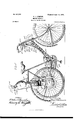
- Fig. (5 shows the application of a motor-wheel as the rear wheel of a bicycle.
- Fig. 7 is a longitudinal section through the carbureter-tank, and Fig. 8 is a detail of construction.
- the road or driving wheel A of the motorwheel (illustrated in Figs. 1 and 2) is constructed after the manner of an ordinary cycle-wheel and made sufficiently stout to withstand the additional wear and tear caused by its motor.
- Its hub A is made hollow throughout.
- a motor B is arranged on one side of the wheel A, and the motor-shaft B' is passed through the hub A' and provided on the other side of the wheel A with a flywheel C, which acts as a counterpoise to the weight of the motor B.
- the ends of the hub A' are provided with ball-bearin gs A3, formed in lugs A3, adapted to be bolted to the blades of a cycle -fork.
- Each of the lugs A3 is split, preferably at its base, and provided with projections A4, through which is passed a bolt A3, Fig. 8.
- the motor-shaft B is driven direct frogm the pistonrod B2 of the motor B by means f a crankdisk B3 and pin B4, arranged within the crank-chamber B5 of the motor, but drives the hub A', and consequently the driving or road wheel A, through the medium of reducing-gear D.
- the reducing-gearD comprises a pinion D', preferably ent on the shaft B', and whichI engages with two wheels D2, mounted on an arm D3, each wheel D3 being free to turn upon its stud or pivot D4, by which it is secured to the arm D3.
- the arm D3 is provided with an extension or sleeve D3, which acts as a bearing-surface for the shaft B and to which the hub A' is fixed in any convenient manner.
- An annular internally-toothed wheel D6 is secured to one of the lugs A3 and surrounds and engages with the wheels D3. ⁇ Vhen in operation, this IOO e acacia wheel D6 acts as a fixed point of bearing for the wheels D2, as hereinafter described.
- the whole of the gear which, as may be clearly seen from the drawings, Figs. l and 2, lies within the outer annular wheel D(i is completely covered in by the plate D1, held in position over the open side of the annular wheel D6 by means of bolts D8, which pass through the plate and secure it to lugs D2, with which the wheel D6 is provided.
- the motor is of the well-known De Dion type, and, apart from the method of applying it to the motor-wheel, forms no part of ythis invention.
- the combustible mixture is supplied to the cylinder by a pipe BGand enters through a suction-valve B1.
- the charge is ignited by the tube B8, rendered incandescent by a burner in the well-known manner, or electric ignition may be used.
- the exhaust-gases pass out by the exhaust-valve B2 through the pipe B10 and silencer B11.
- the exhaust-valve is operated by a cam B12, geared to the motor-shaft B' by pinions B12.
- the crank-chamber B5 of the motor is provided with a circular flanged projection B14, by which it is secured to the plate D7 of the annular wheel D6. This circular flanged projection is cut away at the lower side for the sake of lightness.
- a sleeve or hollow extension B15 is secured to or cast on the crank-chamber B5 and forms a bearing for the end of the motor-shaft B.
- the operation is as follows:
- the motor having been started causes the shaft B', and consequently the pinion D', to rotate at a high speed.
- the wheels D2 by means of their engagement with the pinion D', are also made to revolve on their pivots D4; but owing to their engagement with the fixed wheel D6 they are compelled to travel around the pinion D' as they revolve, carrying with them the arm D3, upon which they are mounted.
- the arm D3 is provided with an extension or sleeve D5, which carries the hub A' of the wheel A fast upon it, and thus the wheel A is caused to rotate in the same direction as the shaft B', but at a reduced speed.
- Fig. 3 shows a motor-wheel arranged as in Figs. 1 and 2 applied as the front wheel of a tricycle.
- the carbureted air, lubricatingoil, and fuel for the burner for the ignitiontube are supplied from acommon carburetertank F, supported above the Wheel A from the cycle-fork by a bracket. (Not shown in the.
- Theinternal arrangement of the tank ⁇ F is shown in Fig. 7.
- the tank is divided into three compartments F' F2 F3 by partitions F4 F5.
- the lubricating-oil is carried in the compartment F', and may be fed to the parts needing lubrication by a pipe, which may communicate with the cock F6.
- the carbureter is arranged in the compartment F2 and is of known construction, and in itself forms no part of the present invention.
- the carbureter is provided with the usual plug-valves F7 F8 for regulating the admission of air to the vapor from the oil or spirit contained in the carbureter and the admission of the combustible charge to the pipe B6 and thence to the motor, respectively.
- the valve FS is operated by the usual handle F9, Fig. 3; but the valve F7 is controlled by a lever F10, which carries a threaded link F11.
- the link F11 is received by a correspondingly-threaded sleeve F12, which is'convnected by a swivel-joint to a bracket F12,
- the sleeve F12 is provided with an enlarged portion F11, by which it may easily be rotated, so as to screw more of the link F11 into or out of it according to the direction it is desired to operate the valve.
- This valve requires nice adjustment this arrangement for its control is to be preferred to the usual handle as used for the valve F2.
- the oil for the burner is carried in the compartment F3, which is provided with the usual force-pump F16, by which a slight air-pressure may be made to bear upon the surface of the oil.
- the oil passes to the burner G by a pipe G', controlled by a cock F1T at the bottom of the tank F.
- the burner G is surrounded by a suitable casing G2, which also incloses the ignition-tube in the usual Well-known manner.
- the lamp-casing G2 may bev provided with one or more apertures G3, closed by plain or colored glass or talc.
- a lever H is provided within easy reach of the rider and communicates, by means of a link H' and lever H2, with the exhaust-valve B2.
- the lever H2 is pivoted at H2, Fig. 2, and the opposite end to that to which the link H' is connected is bifurcated and engages with the valve-rod or part which operates the valve-rod, Fig. l, so that by raising the lever H the exhaust-valveBgisimmediatelyopened.
- a second lever H1 similarly arranged operates a band-brake on the rear axle of the tricycle in any well-known manner.
- the operation of the motor-Wheel has been already described.
- the tricycle is provided with the ordinary pedal and crank driving mechanism, and the motoris started by pedaling the whole machine torward.
- a cock I is provided at the acacia top of the cylinder and when open permits the ingress and egress of air to and from the cylinder, and thus reduces the suction of the piston.
- the cock I is closed.
- a lever I' arranged within easy reach of the rider at the side of the carbureter-tank F and connected by a connectingrod l2 to the lever which controls the cock l permits the rider to open or close the said cock while mounted. 1f preferred, the cock I may be dispensed with and the exhaust-valve opened slightly by means of the lever ll until the motor is started.
- Figs. l and 5 illustrate the application of the motor-wheel as a rear driving-wheel of a tricycle.
- the tricycle shown is of the well known Olympia tandem type, and in itself forms no part of the present invention.
- the general arrangement of the 1notor-wheel is the same as that described with reference to Figs. l, 2, and 3; but some details are slightly modified and mechanism is added for starting the motor either with or without moving the whole tricycle.
- the hub A' of the wheel A is in this case not mounted in ball-bearings, and does not extend through the lugs A0, but is mounted. free on the motor-shaft B, and the lugs Ai1 are provided with plain bearings A7, in which the shaft B runs.
- the reducing-gear D is placed between the lug A3 and the hub A of the wheel A, and the lug A3 is enlarged to receive the flanged circular extension B11 of the motor B, which is thus bolted direct upon it.
- the wheel D0 of the gear D is mounted free upon the outside of the bearing A1, formed on the lug A3, to which the motor is attached, and is provided on its outer periphery with a bandbrake D10, by which it may at any time be held stationary or allowed to run idle.
- the wheels D2 are mounted direct upon the spokeflange of the wheel A, the iiange being made sufficiently large for this purpose, thus dis ⁇ pensing with the arm D0.
- the gear D is shown in Fig. as arranged for three wheels D2. Anynumber of wheels D2may, in fact, be used for this form of gear, so that the pinion D' may be supported all around, if desired.
- a sprocket-wheel J On that side of the hub A opposite to that upon which the gear D is arranged is mounted a sprocket-wheel J, which may be driven when required by the usual chain-and-pedal mechanism with which the tricycle is provided.
- the sprocket J is provided with an annular recess J and is mounted free upon the extension A7 of the lug A3. The sprocket is thus free to turn in either direction and is independent of the hub A', and consequently the wheel A.
- the recess J' is arranged the usual well-known form of roller-and-cam friction-clutch, having rollers J2 and a cam J0, which is fast upon the motor-shaft B.
- this starting mechanism is as follows: Presuming it is desired to start the motor without moving the whole tricyclc the rider slacks the band-brake D10 and pedals forwardas if to propel the tricycle. ⁇ Vhen pedaling in this direction, the sprocket J engages the cam J 3 by means of the rollers J 2 and causes the motor-shaft B to whichthe cam is keyed or otherwise secured to revolve. The motor B will thus be started, but no motion will be imparted to the road-wheel A, as the pinion D' of the connecting-gear D, although revolving, only causes the wheels D2 to revolve and drive around the wheel D0. The moment, however, the band-brake D10 is tightened, so that the wheel D0is held stationary, the wheels D2 will commence to travel around the pinion D, as before described, thus causing the hub A upon which they are carried to revolve.
- the band-brake D10 need not be slackened for starting; but the motor may be started and the tricycle propelled forward at the same time. It will be understood that as soon as the motor is started the pedals may be held stationary and the friction-clutch allowed to overrun.
- the carbureter-tank F is arranged above the wheel A, as in the case in which the motor-wheel is described as used for the front wheel of a tricycle, and is supported from the rear fork of the machine by a bracket F10.
- the motor is in this case provided with the well-known De Dion electric-ignition device, which, however, forms no part of the present invention.
- the batteries for the ignitionspark are inclosed in a box or casing K, carried upon the framing of the tricycle, and the sparking-coil is inclosed in the compartment F3 of the carbureter-tank F.
- the timing device K is arranged at the side of the motor B, the timing-cam being mounted on the same shaft as that which carries the cam for operating the exhaust-valve B0 of the motor B.
- the bandbrake D10 is operated by a handle D11, within easy reach of one of the riders.
- the handle D11 is threaded and receives a spindle D12, correspondingly threaded.
- the spindle D12 passes freely through a lug D13, secured to the frame of the machine.
- An arm D11, hinged or pivoted to the frame at D15, is provided with a jaw D10, which receives the end of the spindle D12 and is hinged to it by a pin D11, passed through the jaw D1G and spindle D12.
- the spindle D12 is thus prevented from turning when the handle D11 is revolved, but is connected to the lever D14 by a hingejoint.
- a wire D10 attached at one end to the end of the spindle D12 or to the jaw end of the lever D11,is connected at its other end to a lever D10, to which both ends o t' the band-brake D10 are attached.
- the lever D10 is pivoted to a lug on the frame at D20, and one end of the band-brake D10 is connected to the lever D10 on one side of the pivot D20,v and the other end is connected at D21 to that portion of the lever which projects beyond the pivot D20.
- the spindle D12 is drawn up through it by means of its thread, and thus raises the end of the lever D14 and puts a tension on the wire D12.
- the lower end of the lever D10 is thus drawn upward, together with the end of the band-brake D10, attached on that side of the pivot D20; but the other end of the lever D10 is at the same time depressed and draws down the end of the band-brake D10, attached at D21, so that the band-brake is by this means tightened from both ends.
- the handle D11 is revolved in the opposite sense, the spindle D12 and end of the lever D11 are lowered, thus slackening the wire D12, which then permits the band-brake D10 to fall loose.
- valve F2 by which the amount of carbureted air admitted to the pipe B0 and thence to the cylinder of the lnotor B is regulated, is brought Within reach of one of the riders of the tricycle by a handle F10, arranged conveniently in front of one of the seats and having a detent F20 and rack F21, whereby it may be retained in any position in which it may be placed.
- the handle F19 is conveniently connected by a connecting-rod F22, a bell-crank lever F22, and a second connecting-rod F21 to the lever F0, by which the valve'F2 is operated.
- a handle K2 is also arranged within easy reach of one of the riders for completing or breaking the electric circuit from the batteries K to the electric-ignition device when desired.
- the lever H for operating the exhaust is connected to Ithe lever H2, Fig. 2, by a wire H0.
- the lever H2 is for this purpose modified and formed as a bellcrank lever, as indicated by the dotted portion H5, having the Wire H0 attached.
- the exhaust-valve B0 is opened by raising the lever H, which, pulling on the wire H0, raises the forked end of the lever H2.
- Vhen the lever H is released, the valve closes by means of its spring and brings the lever H2 back into its normal position.
- the wire H0 may be carried along the framing from the leverH to the lever H2 in any convenient manner-as, for instance, is hereinafter described with reference to Fig. G.
- Fig. 6 illustrates the application of a motor- Wheel as the rear wheel of a bicycle. Vith the exception of one or two slight modications the various parts are arranged as in the tricycle illustrated in Fig. il.
- the carbureter-tank F which is larger than that shown in Fig. 4, is carried by an additional piece of framing L L, built up on the rear fork of the machine and is secured to the framing L L by the bracket F18 and one or more ties L'. lf preferred, however, the carbureter-tank F may be made smaller and arranged as in the reardriving tricycle described above.
- the band-brake D10 and exhaust-valve B2 are operated as described with reference to the rear-driving tricycle, one or two additional pulleys and bell-cranks being provided to guide the operating-wires.
- the handles D11 and F10 for operating the band-brake and valve, respectively, are arranged at the head of the machine.
- the wire D18 from the lever D14 is passed over a pulley at D22 and over a second pulley at D23 to the lever D10.
- the bellcrank F22 operated by the lever F10, is connected to the link F21 ⁇ (which operates the lever F for the purpose described above) by means of two additional links and bell-cranks F25 F2G and F21 F22, respectively.
- the link H and handle H for operating the exhaustvalve are arranged as an ordinary plungerbrake, the shoe or other brake mechanism being attached to the end of the link.
- link H is provided with a projection H7, which engages a bell-crank H8, pivoted at H9 to the frame of the machine.
- a wire H10 connects the bell-crank HEx to a lever H11, pivoted at H12, and to the lever H11 one end of the wire H0 is attached, the other end of which is, as already described, secured to the end H5 of the valve-operating lever
- the link H' may be adjusted, as is usual, with ordinary plunger-brakes, so that by proper adjustment the lever H may be made to open the exhaustvalve B only when slightly raised, but when fully raised may be arranged to apply any Well-known form of tire or rim brake.
- the cock I may be operated by the rider reaching slightly behind the saddle, or it may be connected by suitable links and cranks to a handle arranged in front on the handle-bars or head of the machine.
- the various connections between the operating-handles and valve or other parts operated by such handles may be variously arranged to suit the requirements of different riders or different forms of machines to which it may be desired to apply the motor-wheel; also, the motor-wheel may be applied as the front wheel of a bicycle and arranged as in the front-driving tricycle described with reference to Fig. 3, and the frame may be either in the form of a ladys or womans machine.
- the rear-driving tricycle need not be of the Olympia pattern and may be adapted to carry one or any other number of persons Within reasonable limits.
- the hub A' may be provided with ball-bearings instead of plain bearings, as shown in Figs. 4 and 5, and ball-bearings may, if preferred, be provided between the shaft B' and the hub A in any of the arrangements described; also, the gear D, with its bandbrake D10, may be arranged outside the fork between the motor B and the lug A3 in asimilar manner to the arrangement shown in Figs. l, 2, and 3, provision being, however, made for the Wheel D0 to revolve when the bandbrake is slack.
- any of the above arrangements may be also provided with more than one set of speed-gear, if desired, so that different speed may be obtained by tightening the band-brake on the set of gear required and slackening that or those on the set or sets not required.
- the different sets of gear may be arranged side by side or one or more on IOO IIO
- the Amotor-wheel might be applied to other forms of vehicles besides cycles. To do this, it is only necessary to provide the vehicle to which the motor-wheel is to be applied with one or more supports to receive the lugs A3.
- a vehicle could thus be provided with four motor-wheels, two being arranged to steer, or ordinary steering-wheels could be used, and two motor-wheels for driving.
- the motorwheels may, in fact, it' desired, be applied wherever an ordinary road-wheel is at present used. Again, the same arrangement as is herein described might be used for driving through the medium of other machinery.
- the mechanism arranged, as described might be secured beneath a vehicle, the roadwheel A removed, and a fast and loose pulley mounted in its place. rlhe driving-pulley may then be arranged to drive by means of beltiug onto any desired form of gear.
- the term rigid member is the crank-chamber of the cylinder provided with a bearing through which the motor-shaft is projected.
- a motor-driving apparatus the combination with a driving-wheel, of a motor mounted at one side of it, a motor-shaft, bearings on the drivin g-wheel for the motor-shaft, arigid member connecting the motor-cylinder with the motor-shaft, a fly-wheel operatively connected with the motor-shaft, mounted concentrically with the driving-wheel and at the other side of it, and speed-gear operatively connecting the motor-shaft and the drivingwheel; substantially as set forth.
- a motor-driving apparatus the combination with a driving-wheel, of a hollow axle or hub therefor, a motor mounted at one side of that wheel, a motorshaft passed through the hub, bearings on the hub for the motor-shaft, a rigid member connecting the motor-cylinder with the motor-shaft, a ilywheel mounted concentrically with the driving-wheel and at the other side of it and operatively connected with the motor-shaft, and speed-gear operatively connecting the motor-shaft and the driving-wheel; substantially as set forth.
- a motor-driving apparatus the combination with a drivin g-wheel, of a hollow axle or hub, bearings to support that hub, a motor mounted at one side of the driving-wheel, a meten-shaft extending through the hubbearings on the hub for the motor-shaft,'a rigid member connecting the motor-cylinder with the motor-shaft, a iiy-wheel operatively connected with the motor-shaft and concen tric with the driving-wheel and at the side thereof opposite to that at which the motor is placed, a central pinion on the motor-shaft, a gear-wheel pivoted on the hub and geared with the pinion, and an annular gear-ring geared with that gear-wheel; substantially as set forth.
- a motor-driving apparatus the combination with a driving-wheel, of ahollow aXlc or hub, bearings to support that hub, a motor mounted at one side of the driving-wheel, a motor shaft extending through the hub,
Landscapes
- Engineering & Computer Science (AREA)
- General Engineering & Computer Science (AREA)
- Mechanical Engineering (AREA)
- Arrangement Or Mounting Of Propulsion Units For Vehicles (AREA)
Description
Patented Sept. l2, |899.
7 Sheets-Sheet l,
H. J. LAWSON.
MOTOR VEHICLE.
(Application filed Mar. 2B, 1899.)
M t. lllk MIM;
No. 633,0l4.
(No Model.)
ATTORNEYS.
No. 633,0l4.
Patented sept. l2, |899.
A H. .L I AwsoN.
MOTOR VEHICLE.
(Applicazion med mu. 2e, 1 a99.)
7 Sheets-Sheet 2.
(No Model.)
/N VEN 70H ef-@M5217 @wm W/TNESSES A TTOHNEY5- Tm: cams PETERS so, Pham-uwe.. whsnmorcm. DA c,
Patented Sept. I2, |899.
H. J. LAWSON.
MOTOR VEHICLE.
(Application filed Mar. 28, 1899.)
7 Sheets-Sheet 3,
(No Model.)
A TTOHNE Y6.
No. 633,0l4.
Pa'nted sept. l2, |899. H. .1. LAwsoN.
MOTOR VEHICLE. (Application led Mar. 28, 1899.)
7 Sheets-Sheet 4 (No Model.)
W/ TNE SSE S A TTOHNE X5? Patented Sept. i2, 1899.
No. 633,0l4.
H. J. LAWSON.
MOTOR VEHICLE.
(Application filed Mar. 28, 1899.)
7 Sheets-Sheet 5.
(No Model.)
Vl Du /lll/ 7 Vll W/ TNE SSE S 'ma wams Perm; co, wom-uma wAsHmamN. o. c
Patentd Sept. I2, |899.
No. 633,0l4.
H. J. LAWSON.
MOTR VEHIBLE.
(Application led Mar. 28, 1899.)
7 Sheets-Sheet s.
(N0 Model.)
H m m V N ll f A from/Em.
No. 633,014. Paten'ted Sept. I2, |899.A
H. J. LAWSON.
MOTOR VEHICLE.
Application led Nar., 28, 1899.*
xNn Model.) 7 Sheets-Sheet 7.
w/r/vfssfs /N VEN 70H v Jaz ma we confus Prrsus co. moauno., wnsmNn-mn, n. c.
PATENT rtree,
vHENRY .lOllN LAlVSON, OF LONDON, ENGLAND.
MOTOR-VEHICLE.
:SPECIFICATION forming part of Letters Patent No. 633,014, dated September 12, 1899.
Application filed March 28, 1899. b'erial No. 710,820. No modeld To rtl/f whom it may concern.-
Ee it known that I, HENRY JOHN Lawson, a subject of the Queen of England, residing at London, England, have invented certain new and useful Improvements in or Relating to Motor-Driving Apparatus for Cycles and Like Vehicles, (for which I have made application for Letters Patent in Great Britain under No. 2,841, dated February 8, 1899,) of which the following is a specification.
The object of this invention is to construct a wheel with a motor and driving-gear attached which may be readily applied to any existing cycle-fork with as little alteration to the fork as possible, thus enabling the owner of a cycle to convert his machine into a n10- tor-cycle at a comparatively small cost. This complete driving device will hereinafter be referred to as the motor-wheel.
Although the above is the principal object of this invention the saine form of lnotorwheel may be made more heavily to suit other vehicles besides cycles and may, if desired, be used to drive other machinery instead of itself running upon the road.
The principal features of this invention are that the wheel hereinafter called the driving or road wheel is provided with a hollow axle or hub free to revolve in ball-bearings formed one at each end of the hub'in a lug adapted for attachment to the blade of a cycle-fork. A motor is arranged on one side of the wheel, and the motor-shaft passing through the hollow hub of the wheel and extending beyond the farther side of the same is provided with a fly-wheel, which acts as a counterpoise to the motor. The motor-shaft is connected to and drives-the road-Wheel by means of a simple form of speed-reducing gear.
The invention has further reference to details connected with motor vehicles or cycles formed by the application of a motor-wheel to an ordinary cycle or vehicle.
The invention will be clearly understood by reference to the accompanying drawings, in which- Figure 1 is a central vertical section thro ugh a motor-wheel constructed according to this invention and shows one method of attachment to the front fork of a cycle. Fig. 2 is a section of the saine on the lino 2 2 of Fig. l.
' cycle.
Fig. 3 is a perspective view showing one method of applying the motor-wheel to a tri- Fig. 4 is a perspective view showing` another method of doing the saine. Fig. 5 is a central vertical section of the driving and starting mechanism shown in Fig. 4. Fig. (5 shows the application of a motor-wheel as the rear wheel of a bicycle. Fig. 7 is a longitudinal section through the carbureter-tank, and Fig. 8 is a detail of construction.
Like letters indicate like parts throughout the accompanying drawings.
The road or driving wheel A of the motorwheel (illustrated in Figs. 1 and 2) is constructed after the manner of an ordinary cycle-wheel and made sufficiently stout to withstand the additional wear and tear caused by its motor. Its hub A is made hollow throughout. A motor B is arranged on one side of the wheel A, and the motor-shaft B' is passed through the hub A' and provided on the other side of the wheel A with a flywheel C, which acts as a counterpoise to the weight of the motor B. The ends of the hub A' are provided with ball-bearin gs A3, formed in lugs A3, adapted to be bolted to the blades of a cycle -fork. Each of the lugs A3 is split, preferably at its base, and provided with projections A4, through which is passed a bolt A3, Fig. 8. By screwing up. the bolt A5 the sides of the lug are tightened on the cups A6 of the bearing, and thusiprevent their displacement when once adjusted. The motor-shaft B is driven direct frogm the pistonrod B2 of the motor B by means f a crankdisk B3 and pin B4, arranged within the crank-chamber B5 of the motor, but drives the hub A', and consequently the driving or road wheel A, through the medium of reducing-gear D. The reducing-gearD comprises a pinion D', preferably ent on the shaft B', and whichI engages with two wheels D2, mounted on an arm D3, each wheel D3 being free to turn upon its stud or pivot D4, by which it is secured to the arm D3. The arm D3 is provided with an extension or sleeve D3, which acts as a bearing-surface for the shaft B and to which the hub A' is fixed in any convenient manner. An annular internally-toothed wheel D6 is secured to one of the lugs A3 and surrounds and engages with the wheels D3. \Vhen in operation, this IOO e acacia wheel D6 acts as a fixed point of bearing for the wheels D2, as hereinafter described. The whole of the gear, which, as may be clearly seen from the drawings, Figs. l and 2, lies within the outer annular wheel D(i is completely covered in by the plate D1, held in position over the open side of the annular wheel D6 by means of bolts D8, which pass through the plate and secure it to lugs D2, with which the wheel D6 is provided. The motor is of the well-known De Dion type, and, apart from the method of applying it to the motor-wheel, forms no part of ythis invention. The combustible mixture is supplied to the cylinder by a pipe BGand enters through a suction-valve B1. The charge is ignited by the tube B8, rendered incandescent by a burner in the well-known manner, or electric ignition may be used. The exhaust-gases pass out by the exhaust-valve B2 through the pipe B10 and silencer B11. The exhaust-valve is operated by a cam B12, geared to the motor-shaft B' by pinions B12. The crank-chamber B5 of the motor is provided with a circular flanged projection B14, by which it is secured to the plate D7 of the annular wheel D6. This circular flanged projection is cut away at the lower side for the sake of lightness. A sleeve or hollow extension B15 is secured to or cast on the crank-chamber B5 and forms a bearing for the end of the motor-shaft B.
From the above description it will be seen that in applying the motor-Wheel to an ordinary cycle-fork it is only necessary to secure the lugs A2 to the blades of the fork, when all the parts will be heldin place. This may be done by cutting oft the ends of the blades, as at E, and brazing in lugs, such as E', to which the lugs A3 may be bolted. By thus securing the lugs A3 all the other paris of the motor-wheel are, as stated above, held in I position; but the motor may be further secured, if desired, by means of a bracket, such as E2, which may be used as a stay between the upper part of the motor and the blade of the cycle-fork.
The operation is as follows: The motor having been started causes the shaft B', and consequently the pinion D', to rotate at a high speed. The wheels D2, by means of their engagement with the pinion D', are also made to revolve on their pivots D4; but owing to their engagement with the fixed wheel D6 they are compelled to travel around the pinion D' as they revolve, carrying with them the arm D3, upon which they are mounted. As has been described above, the arm D3 is provided with an extension or sleeve D5, which carries the hub A' of the wheel A fast upon it, and thus the wheel A is caused to rotate in the same direction as the shaft B', but at a reduced speed.
Fig. 3 shows a motor-wheel arranged as in Figs. 1 and 2 applied as the front wheel of a tricycle. The carbureted air, lubricatingoil, and fuel for the burner for the ignitiontube are supplied from acommon carburetertank F, supported above the Wheel A from the cycle-fork by a bracket. (Not shown in the.
drawings.) Theinternal arrangement of the tank` F is shown in Fig. 7. The tank is divided into three compartments F' F2 F3 by partitions F4 F5. The lubricating-oil is carried in the compartment F', and may be fed to the parts needing lubrication by a pipe, which may communicate with the cock F6. The carbureter is arranged in the compartment F2 and is of known construction, and in itself forms no part of the present invention. The carbureter is provided with the usual plug-valves F7 F8 for regulating the admission of air to the vapor from the oil or spirit contained in the carbureter and the admission of the combustible charge to the pipe B6 and thence to the motor, respectively. The valve FS is operated by the usual handle F9, Fig. 3; but the valve F7 is controlled by a lever F10, which carries a threaded link F11. The link F11 is received by a correspondingly-threaded sleeve F12, which is'convnected by a swivel-joint to a bracket F12,
fixed to the upper part ot' the carbureter. The sleeve F12 is provided with an enlarged portion F11, by which it may easily be rotated, so as to screw more of the link F11 into or out of it according to the direction it is desired to operate the valve. As this valve requires nice adjustment this arrangement for its control is to be preferred to the usual handle as used for the valve F2. The oil for the burner is carried in the compartment F3, which is provided with the usual force-pump F16, by which a slight air-pressure may be made to bear upon the surface of the oil. The oil passes to the burner G by a pipe G', controlled by a cock F1T at the bottom of the tank F. The burner G is surrounded by a suitable casing G2, which also incloses the ignition-tube in the usual Well-known manner. To avoid carrying an additional lamp to meet the requirements of any act compelling the riders or drivers of road-vehicles to carry a light, the lamp-casing G2 may bev provided with one or more apertures G3, closed by plain or colored glass or talc. A lever H is provided within easy reach of the rider and communicates, by means of a link H' and lever H2, with the exhaust-valve B2. The lever H2 is pivoted at H2, Fig. 2, and the opposite end to that to which the link H' is connected is bifurcated and engages with the valve-rod or part which operates the valve-rod, Fig. l, so that by raising the lever H the exhaust-valveBgisimmediatelyopened. A second lever H1 similarly arranged operates a band-brake on the rear axle of the tricycle in any well-known manner.
The operation of the motor-Wheel has been already described. The tricycle is provided with the ordinary pedal and crank driving mechanism, and the motoris started by pedaling the whole machine torward. To render this less laborious, a cock I is provided at the acacia top of the cylinder and when open permits the ingress and egress of air to and from the cylinder, and thus reduces the suction of the piston. When the motor is started, the cock I is closed. A lever I', arranged within easy reach of the rider at the side of the carbureter-tank F and connected by a connectingrod l2 to the lever which controls the cock l permits the rider to open or close the said cock while mounted. 1f preferred, the cock I may be dispensed with and the exhaust-valve opened slightly by means of the lever ll until the motor is started.
Figs. l and 5 illustrate the application of the motor-wheel as a rear driving-wheel of a tricycle. The tricycle shown is of the well known Olympia tandem type, and in itself forms no part of the present invention. The general arrangement of the 1notor-wheel is the same as that described with reference to Figs. l, 2, and 3; but some details are slightly modified and mechanism is added for starting the motor either with or without moving the whole tricycle. The hub A' of the wheel A is in this case not mounted in ball-bearings, and does not extend through the lugs A0, but is mounted. free on the motor-shaft B, and the lugs Ai1 are provided with plain bearings A7, in which the shaft B runs. The reducing-gear D is placed between the lug A3 and the hub A of the wheel A, and the lug A3 is enlarged to receive the flanged circular extension B11 of the motor B, which is thus bolted direct upon it.
To enable the motor to be started without imparting motion to the whole tricycle, the wheel D0 of the gear D is mounted free upon the outside of the bearing A1, formed on the lug A3, to which the motor is attached, and is provided on its outer periphery with a bandbrake D10, by which it may at any time be held stationary or allowed to run idle. The wheels D2 are mounted direct upon the spokeflange of the wheel A, the iiange being made sufficiently large for this purpose, thus dis` pensing with the arm D0. The gear D is shown in Fig. as arranged for three wheels D2. Anynumber of wheels D2may, in fact, be used for this form of gear, so that the pinion D' may be supported all around, if desired. On that side of the hub A opposite to that upon which the gear D is arranged is mounted a sprocket-wheel J, which may be driven when required by the usual chain-and-pedal mechanism with which the tricycle is provided. The sprocket J is provided with an annular recess J and is mounted free upon the extension A7 of the lug A3. The sprocket is thus free to turn in either direction and is independent of the hub A', and consequently the wheel A. lVithin the recess J' is arranged the usual well-known form of roller-and-cam friction-clutch, having rollers J2 and a cam J0, which is fast upon the motor-shaft B. The operation of this starting mechanism is as follows: Presuming it is desired to start the motor without moving the whole tricyclc the rider slacks the band-brake D10 and pedals forwardas if to propel the tricycle. \Vhen pedaling in this direction, the sprocket J engages the cam J 3 by means of the rollers J 2 and causes the motor-shaft B to whichthe cam is keyed or otherwise secured to revolve. The motor B will thus be started, but no motion will be imparted to the road-wheel A, as the pinion D' of the connecting-gear D, although revolving, only causes the wheels D2 to revolve and drive around the wheel D0. The moment, however, the band-brake D10 is tightened, so that the wheel D0is held stationary, the wheels D2 will commence to travel around the pinion D, as before described, thus causing the hub A upon which they are carried to revolve.
If preferred, the band-brake D10 need not be slackened for starting; but the motor may be started and the tricycle propelled forward at the same time. It will be understood that as soon as the motor is started the pedals may be held stationary and the friction-clutch allowed to overrun.
The carbureter-tank F is arranged above the wheel A, as in the case in which the motor-wheel is described as used for the front wheel of a tricycle, and is supported from the rear fork of the machine by a bracket F10. The motor is in this case provided with the well-known De Dion electric-ignition device, which, however, forms no part of the present invention. The batteries for the ignitionspark are inclosed in a box or casing K, carried upon the framing of the tricycle, and the sparking-coil is inclosed in the compartment F3 of the carbureter-tank F. The timing device K is arranged at the side of the motor B, the timing-cam being mounted on the same shaft as that which carries the cam for operating the exhaust-valve B0 of the motor B.
The bandbrake D10 is operated by a handle D11, within easy reach of one of the riders. The handle D11 is threaded and receives a spindle D12, correspondingly threaded. The spindle D12 passes freely through a lug D13, secured to the frame of the machine. An arm D11, hinged or pivoted to the frame at D15, is provided with a jaw D10, which receives the end of the spindle D12 and is hinged to it by a pin D11, passed through the jaw D1G and spindle D12. The spindle D12 is thus prevented from turning when the handle D11 is revolved, but is connected to the lever D14 by a hingejoint. A wire D10, attached at one end to the end of the spindle D12 or to the jaw end of the lever D11,is connected at its other end to a lever D10, to which both ends o t' the band-brake D10 are attached. The lever D10 is pivoted to a lug on the frame at D20, and one end of the band-brake D10 is connected to the lever D10 on one side of the pivot D20,v and the other end is connected at D21 to that portion of the lever which projects beyond the pivot D20.
rllhe operation of the band-brake is effected as follows: When the handle D11 is rotated IOO IIS
in one direction, the spindle D12 is drawn up through it by means of its thread, and thus raises the end of the lever D14 and puts a tension on the wire D12. The lower end of the lever D10 is thus drawn upward, together with the end of the band-brake D10, attached on that side of the pivot D20; but the other end of the lever D10 is at the same time depressed and draws down the end of the band-brake D10, attached at D21, so that the band-brake is by this means tightened from both ends. )Vhcn the handle D11 is revolved in the opposite sense, the spindle D12 and end of the lever D11 are lowered, thus slackening the wire D12, which then permits the band-brake D10 to fall loose. v
The control of the valve F2, by which the amount of carbureted air admitted to the pipe B0 and thence to the cylinder of the lnotor B is regulated, is brought Within reach of one of the riders of the tricycle by a handle F10, arranged conveniently in front of one of the seats and having a detent F20 and rack F21, whereby it may be retained in any position in which it may be placed. The handle F19 is conveniently connected by a connecting-rod F22, a bell-crank lever F22, and a second connecting-rod F21 to the lever F0, by which the valve'F2 is operated. A handle K2 is also arranged within easy reach of one of the riders for completing or breaking the electric circuit from the batteries K to the electric-ignition device when desired.
The lever H for operating the exhaust is connected to Ithe lever H2, Fig. 2, by a wire H0. (Not shown in Fig. 4.) The lever H2 is for this purpose modified and formed as a bellcrank lever, as indicated by the dotted portion H5, having the Wire H0 attached. (Shown in Fig. 2.) The exhaust-valve B0 is opened by raising the lever H, which, pulling on the wire H0, raises the forked end of the lever H2. )Vhen the lever H is released, the valve closes by means of its spring and brings the lever H2 back into its normal position. The wire H0 may be carried along the framing from the leverH to the lever H2 in any convenient manner-as, for instance, is hereinafter described with reference to Fig. G.
Fig. 6 illustrates the application of a motor- Wheel as the rear wheel of a bicycle. Vith the exception of one or two slight modications the various parts are arranged as in the tricycle illustrated in Fig. il. The carbureter-tank F, which is larger than that shown in Fig. 4, is carried by an additional piece of framing L L, built up on the rear fork of the machine and is secured to the framing L L by the bracket F18 and one or more ties L'. lf preferred, however, the carbureter-tank F may be made smaller and arranged as in the reardriving tricycle described above. The band-brake D10 and exhaust-valve B2 are operated as described with reference to the rear-driving tricycle, one or two additional pulleys and bell-cranks being provided to guide the operating-wires. The handles D11 and F10 for operating the band-brake and valve, respectively, are arranged at the head of the machine. The wire D18 from the lever D14 is passed over a pulley at D22 and over a second pulley at D23 to the lever D10. The bellcrank F22, operated by the lever F10, is connected to the link F21`(which operates the lever F for the purpose described above) by means of two additional links and bell-cranks F25 F2G and F21 F22, respectively. The link H and handle H for operating the exhaustvalve are arranged as an ordinary plungerbrake, the shoe or other brake mechanism being attached to the end of the link. The
link H is provided with a projection H7, which engages a bell-crank H8, pivoted at H9 to the frame of the machine. A wire H10 connects the bell-crank HEx to a lever H11, pivoted at H12, and to the lever H11 one end of the wire H0 is attached, the other end of which is, as already described, secured to the end H5 of the valve-operating lever The link H' may be adjusted, as is usual, with ordinary plunger-brakes, so that by proper adjustment the lever H may be made to open the exhaustvalve B only when slightly raised, but when fully raised may be arranged to apply any Well-known form of tire or rim brake.
The cock I may be operated by the rider reaching slightly behind the saddle, or it may be connected by suitable links and cranks to a handle arranged in front on the handle-bars or head of the machine.
It will be understood that the various connections between the operating-handles and valve or other parts operated by such handles may be variously arranged to suit the requirements of different riders or different forms of machines to which it may be desired to apply the motor-wheel; also, the motor-wheel may be applied as the front wheel of a bicycle and arranged as in the front-driving tricycle described with reference to Fig. 3, and the frame may be either in the form of a ladys or gentlemans machine. The rear-driving tricycle, too, need not be of the Olympia pattern and may be adapted to carry one or any other number of persons Within reasonable limits.
Further, the hub A' may be provided with ball-bearings instead of plain bearings, as shown in Figs. 4 and 5, and ball-bearings may, if preferred, be provided between the shaft B' and the hub A in any of the arrangements described; also, the gear D, with its bandbrake D10, may be arranged outside the fork between the motor B and the lug A3 in asimilar manner to the arrangement shown in Figs. l, 2, and 3, provision being, however, made for the Wheel D0 to revolve when the bandbrake is slack. Any of the above arrangements may be also provided With more than one set of speed-gear, if desired, so that different speed may be obtained by tightening the band-brake on the set of gear required and slackening that or those on the set or sets not required. The different sets of gear may be arranged side by side or one or more on IOO IIO
one side of the wheel, and ditto on the other, as found convenient.
The Amotor-wheel might be applied to other forms of vehicles besides cycles. To do this, it is only necessary to provide the vehicle to which the motor-wheel is to be applied with one or more supports to receive the lugs A3. A vehicle could thus be provided with four motor-wheels, two being arranged to steer, or ordinary steering-wheels could be used, and two motor-wheels for driving. The motorwheels may, in fact, it' desired, be applied wherever an ordinary road-wheel is at present used. Again, the same arrangement as is herein described might be used for driving through the medium of other machinery. Thus the mechanism arranged, as described, might be secured beneath a vehicle, the roadwheel A removed, and a fast and loose pulley mounted in its place. rlhe driving-pulley may then be arranged to drive by means of beltiug onto any desired form of gear.
I have used in the claims the term rigid member and I desire it understood that this term is not restricted in its application to a fixed part of the frame--such, for instance, as the blades of a cycle-fork or other similar parts to which the motor maybe attachedbut is intended to cover any member bearing such relation to the driving mechanism as to adapt it to so connect the motor-cylinder and the motor-sh att as to entirely obviate any end thrust between the pistou and cylinderbeing taken up by the blade of the fork or other equivalent member ot' the vehicleframe. Thus, as is seenin Fig. l of the drawings, the rigid member is the crank-chamber of the cylinder provided with a bearing through which the motor-shaft is projected. In this case all end thrust between the cylinder-piston and the crank is sustained by the cylinder and the crank-chamber, which are bolted together, and not by the blade of the fork to which the cylinder is secured by the light bracket E2, the object of which last-named part is merely to keep the cylinder in a vertical position.
I claiml. In a motor-driving apparatus, the combination with a driving-wheel, of a motor mounted at one side of it, a motor-shaft, bearings on the drivin g-wheel for the motor-shaft, arigid member connecting the motor-cylinder with the motor-shaft, a fly-wheel operatively connected with the motor-shaft, mounted concentrically with the driving-wheel and at the other side of it, and speed-gear operatively connecting the motor-shaft and the drivingwheel; substantially as set forth.
2. In a motor-driving apparatus, the combination with a driving-wheel, of a hollow axle or hub therefor, a motor mounted at one side of that wheel, a motorshaft passed through the hub, bearings on the hub for the motor-shaft, a rigid member connecting the motor-cylinder with the motor-shaft, a ilywheel mounted concentrically with the driving-wheel and at the other side of it and operatively connected with the motor-shaft, and speed-gear operatively connecting the motor-shaft and the driving-wheel; substantially as set forth.
3. In a motor-driving apparatus, the combin ation with a drivin g-wheel, of a hollow axle or hub, bearings to support that hub, a motor mounted at one side of the driving-wheel, a meten-shaft extending through the hubbearings on the hub for the motor-shaft,'a rigid member connecting the motor-cylinder with the motor-shaft, a iiy-wheel operatively connected with the motor-shaft and concen tric with the driving-wheel and at the side thereof opposite to that at which the motor is placed, a central pinion on the motor-shaft, a gear-wheel pivoted on the hub and geared with the pinion, and an annular gear-ring geared with that gear-wheel; substantially as set forth.
4. In a motor-driving apparatus, the combination with a driving-wheel, of ahollow aXlc or hub, bearings to support that hub, a motor mounted at one side of the driving-wheel, a motor shaft extending through the hub,
bearings on the hub for the motor-shaft, a`
rigid member connecting the motor-cylinder with the motor-shaf t, a iiy-wheel operatively connected with the motor-shaft and concentric with the driving-wheel, and at the side thereof opposite to that at which the motor is placed, a central pinion on the motor-shaft, a gearwheel pivot-ed on the hub and geared with the pinion, an annular gear-wheel geared also with the said pivoted wheel, and means for controlling the rotation of the annular wheel, for the purpose set forth.
In witness whereof I have hereto set my hand in the presence of the two subscribing witnesses.
HENRY JOHN LAIVSON.
Witnesses:
ALFRED MosLEY HAYWARD, LAUcHLAN KENNEDY.
IOO
Priority Applications (1)
| Application Number | Priority Date | Filing Date | Title |
|---|---|---|---|
| US71082099A US633014A (en) | 1899-03-28 | 1899-03-28 | Motor-vehicle. |
Applications Claiming Priority (1)
| Application Number | Priority Date | Filing Date | Title |
|---|---|---|---|
| US71082099A US633014A (en) | 1899-03-28 | 1899-03-28 | Motor-vehicle. |
Publications (1)
| Publication Number | Publication Date |
|---|---|
| US633014A true US633014A (en) | 1899-09-12 |
Family
ID=2701607
Family Applications (1)
| Application Number | Title | Priority Date | Filing Date |
|---|---|---|---|
| US71082099A Expired - Lifetime US633014A (en) | 1899-03-28 | 1899-03-28 | Motor-vehicle. |
Country Status (1)
| Country | Link |
|---|---|
| US (1) | US633014A (en) |
Cited By (2)
| Publication number | Priority date | Publication date | Assignee | Title |
|---|---|---|---|---|
| US2586702A (en) * | 1947-01-20 | 1952-02-19 | Obram Nicolas | Auto cycle and like power assisted vehicle and motor for such vehicle |
| US2588229A (en) * | 1949-03-23 | 1952-03-04 | Speedwheel N V | Hub motor with coupling |
-
1899
- 1899-03-28 US US71082099A patent/US633014A/en not_active Expired - Lifetime
Cited By (2)
| Publication number | Priority date | Publication date | Assignee | Title |
|---|---|---|---|---|
| US2586702A (en) * | 1947-01-20 | 1952-02-19 | Obram Nicolas | Auto cycle and like power assisted vehicle and motor for such vehicle |
| US2588229A (en) * | 1949-03-23 | 1952-03-04 | Speedwheel N V | Hub motor with coupling |
Similar Documents
| Publication | Publication Date | Title |
|---|---|---|
| US20230406434A1 (en) | Two-wheeled vehicle | |
| US7753157B1 (en) | Motorcycle with pedals | |
| US4397369A (en) | Power drive | |
| US4848503A (en) | Small snowmobile and drive arrangement therefor | |
| JP6766080B2 (en) | Lean vehicle | |
| US633014A (en) | Motor-vehicle. | |
| US7225705B2 (en) | Power transmission device and assembling method for a motorcycle | |
| JPH08175477A (en) | Power switching device of engine and motor of motor cycle | |
| US667062A (en) | Motor-cycle. | |
| JP2010236519A (en) | Internal combustion engine | |
| US632474A (en) | Motor-driven vehicle. | |
| JPH0811771A (en) | Bicycle with motor | |
| US715889A (en) | Means for propelling cycles or other light vehicles. | |
| US713350A (en) | Driving mechanism for bicycles. | |
| US987728A (en) | Self-propelled vehicle. | |
| US700209A (en) | Motor driving apparatus for cycles. | |
| NL2028537B1 (en) | Mid-drive module for a pedal-powered vehicle | |
| JPS6141683A (en) | Power transmission gear for bicycle with prime mover | |
| US659956A (en) | Motor-cycle. | |
| US589531A (en) | Velocipede | |
| US670010A (en) | Motor-bicycle. | |
| US1182542A (en) | Motor-cycle. | |
| US1284970A (en) | Motor-wheel. | |
| US653224A (en) | Motor-vehicle. | |
| US673336A (en) | Motor-cycle. |