US6325199B1 - Pallet conveyor apparatus - Google Patents
Pallet conveyor apparatus Download PDFInfo
- Publication number
- US6325199B1 US6325199B1 US09/409,038 US40903899A US6325199B1 US 6325199 B1 US6325199 B1 US 6325199B1 US 40903899 A US40903899 A US 40903899A US 6325199 B1 US6325199 B1 US 6325199B1
- Authority
- US
- United States
- Prior art keywords
- pallet
- rail structure
- pallets
- distance
- upper track
- Prior art date
- Legal status (The legal status is an assumption and is not a legal conclusion. Google has not performed a legal analysis and makes no representation as to the accuracy of the status listed.)
- Expired - Fee Related
Links
Images



Classifications
-
- B—PERFORMING OPERATIONS; TRANSPORTING
- B65—CONVEYING; PACKING; STORING; HANDLING THIN OR FILAMENTARY MATERIAL
- B65G—TRANSPORT OR STORAGE DEVICES, e.g. CONVEYORS FOR LOADING OR TIPPING, SHOP CONVEYOR SYSTEMS OR PNEUMATIC TUBE CONVEYORS
- B65G17/00—Conveyors having an endless traction element, e.g. a chain, transmitting movement to a continuous or substantially-continuous load-carrying surface or to a series of individual load-carriers; Endless-chain conveyors in which the chains form the load-carrying surface
- B65G17/002—Conveyors having an endless traction element, e.g. a chain, transmitting movement to a continuous or substantially-continuous load-carrying surface or to a series of individual load-carriers; Endless-chain conveyors in which the chains form the load-carrying surface comprising load carriers resting on the traction element
-
- B—PERFORMING OPERATIONS; TRANSPORTING
- B65—CONVEYING; PACKING; STORING; HANDLING THIN OR FILAMENTARY MATERIAL
- B65G—TRANSPORT OR STORAGE DEVICES, e.g. CONVEYORS FOR LOADING OR TIPPING, SHOP CONVEYOR SYSTEMS OR PNEUMATIC TUBE CONVEYORS
- B65G21/00—Supporting or protective framework or housings for endless load-carriers or traction elements of belt or chain conveyors
- B65G21/20—Means incorporated in, or attached to, framework or housings for guiding load-carriers, traction elements or loads supported on moving surfaces
- B65G21/22—Rails or the like engaging sliding elements or rollers attached to load-carriers or traction elements
-
- B—PERFORMING OPERATIONS; TRANSPORTING
- B65—CONVEYING; PACKING; STORING; HANDLING THIN OR FILAMENTARY MATERIAL
- B65G—TRANSPORT OR STORAGE DEVICES, e.g. CONVEYORS FOR LOADING OR TIPPING, SHOP CONVEYOR SYSTEMS OR PNEUMATIC TUBE CONVEYORS
- B65G23/00—Driving gear for endless conveyors; Belt- or chain-tensioning arrangements
- B65G23/22—Arrangements or mountings of driving motors
-
- B—PERFORMING OPERATIONS; TRANSPORTING
- B65—CONVEYING; PACKING; STORING; HANDLING THIN OR FILAMENTARY MATERIAL
- B65G—TRANSPORT OR STORAGE DEVICES, e.g. CONVEYORS FOR LOADING OR TIPPING, SHOP CONVEYOR SYSTEMS OR PNEUMATIC TUBE CONVEYORS
- B65G2201/00—Indexing codes relating to handling devices, e.g. conveyors, characterised by the type of product or load being conveyed or handled
- B65G2201/02—Articles
Definitions
- the present invention relates to improved solutions for conveying electric machine components (e.g., armatures or stators for electric motors, generators, or alternators) between different processing stations and between machines of the same processing station of a manufacturing line.
- electric machine components e.g., armatures or stators for electric motors, generators, or alternators
- a component of a dynamo-electric machine (e.g., the armature or stator being made) is often carried along the manufacturing line by a conveyor apparatus while mounted on a pallet, which may carry one or more such components.
- the pallet can be encoded in a known way with information regarding the condition of the component or components it is carrying.
- the encoded information can include an identification of the processing steps to be performed, the status of each step, whether the component should be rejected, etc.
- the information can be encoded magnetically, electronically, mechanically, or electromechanically, and a suitable reading device is provided adjacent each processing station to read the information.
- a manufacturing line or processing station includes a plurality of routes, pallets are usually transferred between the routes as necessary. Pallet transfer should be simple and reliable, but should not interfere with the information encoded on the pallet. Moreover, a pallet should be able to convey different size components along the manufacturing line.
- Some manufacturing lines include processing stations with two or more machines that perform the same function (e.g., winding). Two or more machines may be needed at a single processing station to avoid a “bottleneck” when the processing time of a machine is longer than the processing time required by other machines or stations of the same manufacturing line. Transfer between machines of a single station, however, can be mechanically complicated and expensive to manufacture and maintain. Moreover, conventional transfer apparatus can consume substantial floor space, making it difficult for an operator to gain access to components and machines of a processing station.
- a pallet conveyor apparatus that includes a plurality of pallets, at least one substantially horizontal rail structure, at least one loop-shaped conveyor belt, and a drive for causing the conveyor belt to move on an upper track of the rail structure along the rail structure's length.
- Each of the pallets includes a platform having an upper surface adapted to at least partially support a component, and a seat portion having a substantially inverted “U” shape.
- the seat portion of the rail structure has a central surface and two opposing surfaces. The opposing surfaces have a first height and are separated by a first distance.
- the rail structure has a length, an upper track, and two side surfaces.
- the side surfaces have a second height and are separated by a second distance.
- the first distance is larger than the second distance so that the rail structure can fit between a pallet's opposing surfaces. Also, the first and second heights are sufficient to prevent pallets from falling off the rail structure.
- the conveyor belt has an inner belt surface and an outer belt surface.
- the inner belt surface is at least partially disposed on the upper track of the rail structure and the outer belt surface at least partially engages a central surface of a pallet.
- the drive which may be an electric motor, for example, causes the conveyor belt to move along the upper track of the rail structure, thereby causing pallets resting on the conveyor belt to be moved.
- FIG. 1 is an elevational sectional view of an illustrative pallet constructed in accordance with the principles of this invention.
- the pallet is mounted on a rail structure and is supporting an armature.
- FIG. 1 is taken along the line 1 — 1 in FIG. 2 .
- FIG. 2 is a front elevational view of a portion of a manufacturing line, constructed in accordance with the principles of this invention.
- FIG. 3 is a side elevational view of the same portion of the manufacturing line shown in FIG. 2 .
- FIG. 3 is taken along line 3 — 3 of FIG. 2 .
- FIG. 4 is an elevational sectional view of another illustrative pallet constructed in accordance with the principles of this invention.
- the pallet is mounted on a rail structure and is supporting a stator.
- FIG. 5 is a plan view of an illustrative pallet conveyor apparatus in accordance with the principles of this invention.
- FIG. 6 is a plan view of another illustrative pallet conveyor apparatus in accordance with the principles of this invention.
- FIG. 7 is a side elevational view, partly in cross-section, of two abutted illustrative rail sections, such as the ones shown in FIGS. 1-4, in accordance with the principles of this invention.
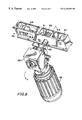
- FIG. 8 is a perspective view of the illustrative drive cartridge shown in FIG. 7, along with an electric motor and gear box, which can be positioned in a rail section for driving a conveyor belt as shown in FIG. 7, in accordance with the principles of this invention.
- FIG. 9 is an elevational view, in cross-section, of the illustrative drive cartridge shown in FIG. 8, taken from line 9 — 9 of FIG. 8, along with the electric motor and gear box, in accordance with the principles of this invention.
- the present disclosure concerns improved solutions for transporting armature or stator assemblies by means of pallets, between processing stations of manufacturing lines.
- FIG. 1 shows pallet 10 supporting various portions of armature 11 (i.e., lamination stack 11 a, and shafts 11 b and 11 c ) on supporting surfaces 12 ′ of seat portion 12 .
- Supporting surfaces 12 ′ extend sufficiently in direction X to be able to support different armatures.
- the underside of pallet 10 is adapted to receive at least part of a rail structure (see below).
- the undersides of pallets 10 and 40 are adapted to receive a single rail structure on which a single belt moves.
- the underside of the pallets can be shaped to receive and engage two or more rails, on which conveyor belts synchronously convey the pallet (not shown). Regardless of the number of rails used, a pallet according to this invention will have an underside shaped to accommodate the one or more rails to ensure accurate translation along the rail without significant lateral motion.
- the underside of pallet 10 is provided with seat 13 having an inverted “U” shape, which is formed by portions 13 ′, 13 ′′, and 13 ′′′.
- Central portion 13 ′ rests on conveyor belt 14
- portions 13 ′′ and 13 ′′′ act as surfaces that abut respectively against sides 15 ′′ and 15 ′′′ of rail structure 15 .
- Upper face 15 ′ of rail structure 15 has a track that supports conveyor belt 14 .
- Narrow gaps are normally present between sides 13 ′′ and 15 ′′, and sides 13 ′′′ and 15 ′′′.
- portions 13 ′′ and 13 ′′′ will move to close the gaps by engaging respectively sides 15 ′′ and 15 ′′′, thereby sustaining the pallet.
- FIG. 2 shows a processing station of a manufacturing line with more than one machine of the same type (for example, two or more winders). Such a station can perform identical manufacturing operations at the same time on a plurality of components. The machines of such a station usually process components singularly. The station shown in FIG. 2 may be needed when the machines of the station require processing times that are longer than other machines of other stations of the line.
- FIG. 2 shows three different pallet routes 20 , 21 , and 22 in front of machine M of a processing station.
- Route 20 moves pallets in direction 20 ′ and includes rail structure 15 and conveyor belt 14 on which the pallets rest. The motion aligns the pallets at the machines where they need to be processed.
- Point P represents the position on route 20 where the armatures supported by the pallets can be loaded and unloaded. Successive pallets can form a queue behind the pallet at point P.
- Other machines of the same station (not shown) can also have similar pallet routes for loading and unloading armatures that need processing.
- Route 21 moves pallets in direction 21 ′. Like route 20 , route 21 includes rail structure 15 and conveyor belt 14 on which pallets rest. As indicated in FIG. 2, route 21 transports pallets into the station from an upstream portion of the manufacturing line and transports pallets away from the station to a downstream portion of the manufacturing line after being processed. If desired, route 21 can pass in front of all the machines of the station.
- a pallet moving in direction 21 ′ along route 21 can deliver a work piece (e.g., an armature) to a machine, such as machine M of FIG. 2 .
- Machines of a processing station can be positioned in a sequence along route 21 .
- a pallet is removed from route 21 at position 20 ′′, for example, it can be placed in a queue in front of a machine that is capable of receiving it.
- the first machine of the sequence that has room at the end of its respective queue will receive the pallet.
- a pallet Once a pallet is placed on route 20 , it moves in direction 20 ′ until it reaches position P. At position P, the component is unloaded from the pallet, processed, and reloaded. After being reloaded, the pallet moves to position 20 ′′′ at the end of route 20 where it can be returned to route 21 . Then, the loaded pallet can move in direction 21 ′ to reach the downstream portion of the line.
- Route 22 passes through the station and moves pallets in direction 22 ′.
- Route 22 performs two functions. First, route 22 returns empty pallets from the downstream portion of the line to the beginning of the upstream portion of line. Second, route 22 returns pallets with unprocessed components to route 21 .
- the components that are returned to route 21 from route 22 may be unprocessed because all of the machines along the manufacturing line were unavailable to receive the work pieces when they passed by the machines, loading points, such as point 20 ′. This can occur when the queues formed in front of each machine are unable to accept additional pallets. This can also occur when the machines are under repair or being maintained. In any case, such pallets are returned to route 21 so that they can again try to find a free place in a queue of an operating machine. Routes like these are described, for example, in U.S. Pat. No. 4,984,353 for a winding station.
- conveyor belt 14 moves pallet 11 of FIG. 1 along the length of rail structure 15 .
- pallet 10 will be conveyed synchronously with conveyor belt 14 .
- Conveyor belt 14 can be looped around structure 15 .
- Inner surface of conveyor belt 14 guides along upper surface 15 ′ of structure 15 (e.g., in a track) and can return along the underside of structure 15 .
- Conveyor belt 14 can be driven by any suitable drive, such as an electric motor, which can be located, for example, in or adjacent to structure 15 .
- FIGS. 7-9 For a more complete description of the how an electric motor can be used to drive conveyor belt 14 according to this invention, see FIGS. 7-9, which are described below.
- Pallet 10 has ribs 16 that extend downward in order to reinforce portions 13 ′′ and 13 ′′′ of the “U” shaped seat portion. Pallet 10 may also have side walls 9 with apertures 19 that are opposite each other for providing access to opposing jaws of a transfer gripping unit that may be located at a position along a route, such as at position P of FIG. 2 . Jaws of the transfer gripping unit can thus move through apertures 19 to grasp armature 11 to remove it from pallet 10 , or to release armature 11 when armature 11 is loaded onto pallet 10 .
- Such transfer gripping units are described in Andorlini et al. U.S. Pat. No. 5,253,912, which is hereby incorporated by reference herein.
- FIG. 2 shows mechanical stop S.
- the stop surface of mechanical stop S is positioned to engage the forward face F of pallet 29 , stopping pallet 29 , while the conveyor belt continues to move.
- Pallets can queue up behind first pallet 29 . Once this pallet is stopped, the next pallet in the queue will stop behind the first pallet by engaging forward face F with rear face R of pallet 29 . Preferably, the lower portions of the front and rear faces will abut. Additional successive pallets can also be stopped in the queue by engaging their forward faces with the rear faces of adjacent pallets that have already been stopped. The conveyor belt continues to move as the additional pallets engage each other.
- the pallets can be narrower than conventional pallets. This narrow construction makes it possible to form a queue with a large number of pallets along the length of the rail structure in front of a machine.
- each pallet extends in an upward direction to provide a sufficient surface for engagement between adjacent pallets in a queue.
- the forward and rear faces prevent the pallets from climbing over each other during engagement while the conveyor belt moves below them.
- FIG. 3 shows a side view of the manufacturing line shown in FIG. 2 .
- FIG. 3 shows how routes 20 , 21 , and 22 can be arranged in vertical plane V in front of machine M.
- This arrangement is possible because the rail structure of each route can be vertically connected with support brackets 23 to vertical frame 24 .
- distance X between operator 0 and machine M is much less than the comparable distance when those routes are disposed horizontally, as shown, for example, in U.S. Pat. No. 4,984,353.
- the operator observing machine M has a clearer view of the operations occurring in machine M, and easier access to the armatures being processed on route 20 and transported on routes 21 and 22 .
- FIG. 3 also shows one way that pallets can be transferred between different positions on the routes.
- Gripping unit 25 has gripping jaws 25 ′ and 25 ′′ located at position 20 ′′ where pallets can be transferred from one route to another.
- Gripping jaws 25 ′ and 25 ′′ can move toward each other in vertical plane V and grip a pallet in position G. This is shown in FIG. 3 for a pallet located on route 21 . While gripping the pallet, jaws 25 ′ and 25 ′′ can be upwardly moved along guide bars 26 until seat 13 is aligned with an end of rail structure 15 .
- the jaws can move on guides 27 toward structure 15 to insert seat 13 onto rail structure 15 , as shown in FIG. 1 .
- this movement is into the page.
- the movement is in direction 201 .
- a method of transferring pallets between substantially horizontal rail structures that are positioned in a substantially vertical plane is provided.
- a pallet is conveyed along a first rail structure.
- the pallet is stopped at a point on the first rail structure with a physical stop.
- the pallet is engaged with transfer equipment (e.g., a gripping unit or lift). It will be appreciated that when a gripping unit is used, a portion of the pallet can stop between the jaws of the gripping unit in the second step to prepare for engagement with the pallet in the third step.
- transfer equipment e.g., a gripping unit or lift.
- Pallet 10 can carry pin 271 for encoding information.
- pallet 10 is oriented so that pin 27 ′ is located on the right side of rail structure 15 and can be read by pin reader 28 when pallet 10 is at a particular point along the manufacturing line.
- Seat portion 13 can be designed so that pallet 10 can be raised above structure 15 , rotated by 180° around vertical axis A, and lowered back onto structure 15 .
- pin 27 ′ will be on the opposite side of rail structure 15 (i.e., left side of FIG. 1) with respect to reader 28 so that reader 28 will no longer be able to read (e.g., detect) the pin.
- control unit 28 ′ i.e., a computer
- control unit 28 ′ can determine that pallet 10 has a predetermined condition of armature processing. Based on this condition, an action can be subsequently taken. For example, when the condition of the armature is determined to be unsatisfactory (e.g., after detecting, or not detecting, pin 27 ′), an action can be determining that an armature should not undergo further processing.
- FIG. 4 shows another illustrative pallet 40 that can be constructed in accordance with this invention.
- Pallet 40 supports stator 30 by engaging interior surface 31 of central bore 32 of stator 30 on central column 41 which extends upwardly from pallet 40 .
- the principles of moving and transferring stators between machines and stations of a manufacturing line already described in accordance with this invention are applicable to the pallet of FIG. 4 .
- a pallet according to this invention is preferably structurally symmetric (i.e., symmetric about the vertical plane containing the rail structure) to eliminate misorientation of the pallet during placement on the rail structure.
- FIGS. 5 and 6 show how pallets can be transferred between routes (particularly between routes substantially in a horizontal plane) using an intermediate route that does not include a conveyor belt.
- FIG. 5 shows pallets 54 moving on route 51 in direction 50 ′, pallets 55 moving on arcuate route 52 in direction 50 ′′, and pallets 56 moving on route 53 in direction 50 ′′′.
- Pallets 54 and 56 move along their respective routes by conveyor belts as already described, but pallets 55 move along route 52 by pallet pushers 57 .
- ends 52 ′ and 52 ′′ of route 52 are alignable with respective ends 51 ′ and 53 ′ of routes 51 and 53 .
- Pallet pushers 57 can be driven along track 58 in any conventional way. It will be appreciated that although pallets 54 , 55 , and 56 (shown on respective routes 51 , 52 , and 53 ) do not engage each other to form queues, such engagement is possible. If a queue is formed on route 52 , a single rotating pallet pusher (not shown) could be placed at the upstream end of route 52 to move pallets 55 along route 52 .
- FIG. 6 shows pallets 64 moving on route 61 in direction 60 ′, pallet 65 moving on linear route 62 in direction 60 ′′, and pallets 66 moving on route 63 in direction 60 ′′′.
- Pallets 64 and 66 can be moved along their respective routes by conveyor belts.
- Pallet 65 can be moved along route 62 by rotary pallet pushers 67 and/or linear pallet pushers 67 ′.
- ends 62 ′ and 62 ′′′ of route 62 are alignable with respective ends 61 ′ and 63 ′ of routes 61 and 63 .
- Rotary pallet pushers 67 sweep pallets from route 61 to route 62 and from route 62 to route 63 .
- Linear pallet pushers 67 ′ push pallets 65 along on route 62 .
- pallets can be pushed on and off rail structures with one or more pallet pushers.
- a pallet can be transferred between different routes or different positions of the same route with lifting rods 33 when the pallet has bores 32 adapted to receive such rods.
- Lifting rods 33 can also be used to lift a pallet off of a rail structure to an overhead position required by a machine to process the component on the pallet. It will be appreciated that although the pallet shown in FIG. 1 only includes single bore 32 for receiving single lifting rod 33 , a pallet can have two or more bores for synchronously receiving two or more lifting rods. Although mechanically more complicated, multiple synchronized lifting rods would increase stability by minimizing the cantilever effect normally present with asymmetric approaches.
- FIG. 7 shows a side elevational view, partly in section, of rail structures 70 and 75 .
- Rail structure 70 includes upper rotatable guiding wheels 71 at both upper corners of structure 70 for guiding belt 72 along the upper surface 70 ′ of structure 70 , and lower rotatable guiding wheels 71 ′ at both lower corners of structure 70 for guiding belt 72 along lower surface 70 ′′ of structure 70 .
- Lower guiding wheels 71 ′ also guide belt 72 to drive cartridge 80 , which is positioned within rail structure 70 .
- rail structure 75 also includes a drive cartridge, the cartridge is not shown to simplify FIG. 7 .
- FIG. 8 shows drive cartridge 80 , which includes two fixed position wheels 81 and 82 , as well as motor wheel 83 and tension wheel 84 , for providing a compact folded belt path.
- motor wheel 83 is located near the bottom of cartridge 80 , which is itself placed near the bottom of rail structure 70 .
- drive shaft 85 does not interfere with the lower portions of the inverted “U” structures of pallets (not shown) conveyed along the top of rail structure 70 .
- Drive shaft 85 is powered by motor 88 via gear box 89 .
- gear box 89 allows for motor 88 to be oriented in any convenient way
- FIG. 8 shows motor 88 oriented in a substantially vertical plane to minimize the horizontal distance X between operator O and machine M (see FIG. 3 ).
- FIG. 9 shows an elevational view, in cross-section, of the illustrative drive cartridge shown in FIG. 8 .
- gibs 73 can be provided as means for overcoming looseness of a pallet during loading and/or unloading of a component at a station.
- gibs 73 provides a fixed surface against which a pallet can be precisely positioned during component loading and/or unloading.
- point P represents the position on route 20 where a component supported by a pallet can be loaded and unloaded. Because narrow gaps are normally present between sides 13 ′′ and 15 ′′, and sides 13 ′′′ and 15 ′′′(see FIG.
- the lateral position of a pallet at point P is not precisely known, which makes automatic loading and unloading more difficult. Accordingly, one of the narrow gaps can be closed by pressing the pallet against one of gibs 73 . Because the precise position of the gib would be known, the exact position of the pallet, and therefore the component being carried, would also be known. A pallet at point P can be pressed against one of gibs 73 with any type of actuating device, such as a lateral pusher (not shown).
- the modular nature of the rail structures according to this invention allows for rapid configuration and reconfiguration of manufacturing lines.
- two or more rail structures, each with its own drive cartridge can be placed end-to-end to allow the transfer of pallets therebetween—without the need for a transfer station.
- each rail structure has complementary end shapes to minimize the gap between them.
- rail structures 70 and 75 have substantially vertical ends. In this way, the gap between the two structures can be minimized so that a pallet can be easily and directly delivered from one rail structure to another—without any additional transfer equipment.
- the modular nature of these rail structures also facilitates vertical stacking, as shown in FIGS. 2 and 3. In any case, whether placed end-to-end or stacked vertically, rail structures with internal drive cartridges according to this invention provide a flexible solution to the problem of complex manufacturing lines.
- a transfer station can transfer pallets between substantially vertically oriented rail structures without the use of an intermediate rail structure.
- FIG. 2 shows a front elevational view of a portion of a manufacturing line, including three vertically positioned routes 20 , 21 , and 22 .
- Middle route 21 is the main route and transports pallets to and from the station in downstream direction 21 ′.
- Route 22 which moves in direction 22 ′, moves pallets that are empty to the beginning of the upstream portion of the line and pallets with unprocessed components to route 21 .
- top route 20 moves pallets in downstream direction 201 and aligns the pallets at the machine where they need to be processed.
- transfer of pallets between routes 20 , 21 , and 22 can be effectuated without an intermediate rail structure using, for example, the transfer equipment shown in FIG. 3 .
- a pallet can be transferred between any two routes by lifting the pallet to a position above a first rail structure, moving the pallet to a position above the second rail structure, and then placing the pallet onto the second rail structure. Accordingly, routes 21 and 22 can be made continuous without structural interruptions.
Landscapes
- Engineering & Computer Science (AREA)
- Mechanical Engineering (AREA)
- Automatic Assembly (AREA)
- Intermediate Stations On Conveyors (AREA)
- Branching, Merging, And Special Transfer Between Conveyors (AREA)
Priority Applications (5)
| Application Number | Priority Date | Filing Date | Title |
|---|---|---|---|
| US09/409,038 US6325199B1 (en) | 1998-10-05 | 1999-09-29 | Pallet conveyor apparatus |
| EP99119536A EP0982242B1 (de) | 1998-10-05 | 1999-10-01 | Palettenförderer |
| CA002284381A CA2284381A1 (en) | 1998-10-05 | 1999-10-01 | Pallet conveyor apparatus |
| DE69931317T DE69931317D1 (de) | 1998-10-05 | 1999-10-01 | Palettenförderer |
| US10/016,554 US20020040840A1 (en) | 1998-10-05 | 2001-11-01 | Pallet conveyor apparatus |
Applications Claiming Priority (2)
| Application Number | Priority Date | Filing Date | Title |
|---|---|---|---|
| US10304398P | 1998-10-05 | 1998-10-05 | |
| US09/409,038 US6325199B1 (en) | 1998-10-05 | 1999-09-29 | Pallet conveyor apparatus |
Related Child Applications (1)
| Application Number | Title | Priority Date | Filing Date |
|---|---|---|---|
| US10/016,554 Division US20020040840A1 (en) | 1998-10-05 | 2001-11-01 | Pallet conveyor apparatus |
Publications (1)
| Publication Number | Publication Date |
|---|---|
| US6325199B1 true US6325199B1 (en) | 2001-12-04 |
Family
ID=26800022
Family Applications (2)
| Application Number | Title | Priority Date | Filing Date |
|---|---|---|---|
| US09/409,038 Expired - Fee Related US6325199B1 (en) | 1998-10-05 | 1999-09-29 | Pallet conveyor apparatus |
| US10/016,554 Abandoned US20020040840A1 (en) | 1998-10-05 | 2001-11-01 | Pallet conveyor apparatus |
Family Applications After (1)
| Application Number | Title | Priority Date | Filing Date |
|---|---|---|---|
| US10/016,554 Abandoned US20020040840A1 (en) | 1998-10-05 | 2001-11-01 | Pallet conveyor apparatus |
Country Status (4)
| Country | Link |
|---|---|
| US (2) | US6325199B1 (de) |
| EP (1) | EP0982242B1 (de) |
| CA (1) | CA2284381A1 (de) |
| DE (1) | DE69931317D1 (de) |
Cited By (9)
| Publication number | Priority date | Publication date | Assignee | Title |
|---|---|---|---|---|
| US6443293B2 (en) * | 2000-01-13 | 2002-09-03 | Fata Automation S.P.A. | Transporting installation with conveyor having idling rollers supporting transport members |
| US20040195077A1 (en) * | 2003-04-04 | 2004-10-07 | Velibor Kilibarda | Pallet/skid power roll system |
| US20040197173A1 (en) * | 2003-04-04 | 2004-10-07 | Velibor Kilibarda | Transfer media lift exchange system |
| US6839983B2 (en) | 2001-09-05 | 2005-01-11 | Axis Usa, Inc. | Heating oven for dynamo-electric machine component manufacture |
| US6878203B2 (en) | 2001-02-12 | 2005-04-12 | Axis Usa, Inc. | Resin application system for dynamo-electric machine components |
| US20050190111A1 (en) * | 2000-07-18 | 2005-09-01 | King Patrick F. | Wireless communication device and method |
| US7411552B2 (en) | 2000-07-18 | 2008-08-12 | Mineral Lassen Llc | Grounded antenna for a wireless communication device and method |
| USRE43683E1 (en) | 2000-07-18 | 2012-09-25 | Mineral Lassen Llc | Wireless communication device and method for discs |
| CN110143434A (zh) * | 2019-05-09 | 2019-08-20 | 深圳市诚捷智能装备股份有限公司 | 下料装置及自动卷绕设备 |
Families Citing this family (4)
| Publication number | Priority date | Publication date | Assignee | Title |
|---|---|---|---|---|
| ITPI20020043A1 (it) * | 2002-08-06 | 2004-02-07 | Atop Spa | Pallet per la movimentazione di indotti per motori elettrici su linee di produzione automatica. |
| EP3290168A4 (de) * | 2015-04-28 | 2018-12-12 | Seiko Epson Corporation | Robotersystem und roboter |
| CN106276075A (zh) * | 2016-09-12 | 2017-01-04 | 周杰 | 一种倍速链输送机导轨装置 |
| CN113581747B (zh) * | 2021-08-31 | 2022-11-25 | 中国人民解放军陆军军医大学第二附属医院 | 自动化防丢失标本接收装置 |
Citations (20)
| Publication number | Priority date | Publication date | Assignee | Title |
|---|---|---|---|---|
| GB1261264A (en) | 1968-05-21 | 1972-01-26 | Bosch Gmbh Robert | Improvements in conveyors |
| US3854889A (en) | 1954-07-28 | 1974-12-17 | Molins Organisation Ltd | Automatic production machinery |
| US4042118A (en) * | 1976-03-09 | 1977-08-16 | Schmidt Hans V | Combination roller conveyor and cross-conveyor system |
| US4193312A (en) * | 1977-05-04 | 1980-03-18 | Industrie Pirelli S.P.A. | Trapezoidal driving belt |
| US4237598A (en) | 1965-09-13 | 1980-12-09 | Molins Limited | Manufacturing processes using machine tools |
| US4460966A (en) | 1981-11-27 | 1984-07-17 | The Cross Company | Transfer machine control |
| US4473883A (en) | 1980-04-03 | 1984-09-25 | Toshiba Kikai Kabushiki Kaiha | Machining systems and control systems therefor |
| US4712670A (en) | 1984-12-12 | 1987-12-15 | Volker Burkhardt | Mechanism for the transportation of objects |
| US4713883A (en) | 1985-07-11 | 1987-12-22 | Axis S.P.A. | Production line for pallet mounted electric motor stators |
| US4768727A (en) | 1985-07-18 | 1988-09-06 | Axis S.P.A. | Device for transferring a pallet-mounted electric motor armature to an armature winding formation station |
| US4815673A (en) | 1985-07-15 | 1989-03-28 | Black & Decker Inc. | Streamlined production of electric motor armatures and stators |
| US4892186A (en) * | 1987-01-26 | 1990-01-09 | Ferag Ag | Clock conveyor provided with a plurality of entrainment members |
| US4981207A (en) * | 1988-02-16 | 1991-01-01 | George Kuikka Limited | Tracks for conveyor systems |
| CH682069A5 (en) | 1990-09-27 | 1993-07-15 | Foerdertechnik Ag | Conveyor for piece goods - has laterally connected endless chains which provides jerk and vibration-free running for goods carriers such as pallets and roll containers |
| DE9416155U1 (de) | 1994-10-07 | 1994-11-24 | Wilhelm Karmann GmbH, 49084 Osnabrück | Verschlußvorrichtung für Cabriolet-Verdecke |
| US5441146A (en) * | 1993-05-04 | 1995-08-15 | Robert Bosch Gmbh | Packaging machine |
| US5503264A (en) * | 1993-07-07 | 1996-04-02 | Ferag Ag | Endlessly circulating items transporting apparatus with individual transporting members |
| US5518105A (en) * | 1992-10-23 | 1996-05-21 | Jean Gallay S.A. | Process and device for conveying objects along a circuit and use thereof |
| US5715585A (en) * | 1994-09-11 | 1998-02-10 | A. Roemheld Gmbh & Co. Kg | Work piece machining system |
| US6112886A (en) * | 1999-03-23 | 2000-09-05 | Middlesex General Industries, Inc. | Snap-in runner for conveyor carriers |
Family Cites Families (1)
| Publication number | Priority date | Publication date | Assignee | Title |
|---|---|---|---|---|
| DE9416115U1 (de) * | 1994-10-06 | 1995-08-03 | F+S Automationstechnik GmbH, 74229 Oedheim | Paletten-Stauförderer |
-
1999
- 1999-09-29 US US09/409,038 patent/US6325199B1/en not_active Expired - Fee Related
- 1999-10-01 DE DE69931317T patent/DE69931317D1/de not_active Expired - Lifetime
- 1999-10-01 CA CA002284381A patent/CA2284381A1/en not_active Abandoned
- 1999-10-01 EP EP99119536A patent/EP0982242B1/de not_active Expired - Lifetime
-
2001
- 2001-11-01 US US10/016,554 patent/US20020040840A1/en not_active Abandoned
Patent Citations (20)
| Publication number | Priority date | Publication date | Assignee | Title |
|---|---|---|---|---|
| US3854889A (en) | 1954-07-28 | 1974-12-17 | Molins Organisation Ltd | Automatic production machinery |
| US4237598A (en) | 1965-09-13 | 1980-12-09 | Molins Limited | Manufacturing processes using machine tools |
| GB1261264A (en) | 1968-05-21 | 1972-01-26 | Bosch Gmbh Robert | Improvements in conveyors |
| US4042118A (en) * | 1976-03-09 | 1977-08-16 | Schmidt Hans V | Combination roller conveyor and cross-conveyor system |
| US4193312A (en) * | 1977-05-04 | 1980-03-18 | Industrie Pirelli S.P.A. | Trapezoidal driving belt |
| US4473883A (en) | 1980-04-03 | 1984-09-25 | Toshiba Kikai Kabushiki Kaiha | Machining systems and control systems therefor |
| US4460966A (en) | 1981-11-27 | 1984-07-17 | The Cross Company | Transfer machine control |
| US4712670A (en) | 1984-12-12 | 1987-12-15 | Volker Burkhardt | Mechanism for the transportation of objects |
| US4713883A (en) | 1985-07-11 | 1987-12-22 | Axis S.P.A. | Production line for pallet mounted electric motor stators |
| US4815673A (en) | 1985-07-15 | 1989-03-28 | Black & Decker Inc. | Streamlined production of electric motor armatures and stators |
| US4768727A (en) | 1985-07-18 | 1988-09-06 | Axis S.P.A. | Device for transferring a pallet-mounted electric motor armature to an armature winding formation station |
| US4892186A (en) * | 1987-01-26 | 1990-01-09 | Ferag Ag | Clock conveyor provided with a plurality of entrainment members |
| US4981207A (en) * | 1988-02-16 | 1991-01-01 | George Kuikka Limited | Tracks for conveyor systems |
| CH682069A5 (en) | 1990-09-27 | 1993-07-15 | Foerdertechnik Ag | Conveyor for piece goods - has laterally connected endless chains which provides jerk and vibration-free running for goods carriers such as pallets and roll containers |
| US5518105A (en) * | 1992-10-23 | 1996-05-21 | Jean Gallay S.A. | Process and device for conveying objects along a circuit and use thereof |
| US5441146A (en) * | 1993-05-04 | 1995-08-15 | Robert Bosch Gmbh | Packaging machine |
| US5503264A (en) * | 1993-07-07 | 1996-04-02 | Ferag Ag | Endlessly circulating items transporting apparatus with individual transporting members |
| US5715585A (en) * | 1994-09-11 | 1998-02-10 | A. Roemheld Gmbh & Co. Kg | Work piece machining system |
| DE9416155U1 (de) | 1994-10-07 | 1994-11-24 | Wilhelm Karmann GmbH, 49084 Osnabrück | Verschlußvorrichtung für Cabriolet-Verdecke |
| US6112886A (en) * | 1999-03-23 | 2000-09-05 | Middlesex General Industries, Inc. | Snap-in runner for conveyor carriers |
Cited By (15)
| Publication number | Priority date | Publication date | Assignee | Title |
|---|---|---|---|---|
| US6443293B2 (en) * | 2000-01-13 | 2002-09-03 | Fata Automation S.P.A. | Transporting installation with conveyor having idling rollers supporting transport members |
| US7397438B2 (en) | 2000-07-18 | 2008-07-08 | Mineral Lassen Llc | Wireless communication device and method |
| USRE43683E1 (en) | 2000-07-18 | 2012-09-25 | Mineral Lassen Llc | Wireless communication device and method for discs |
| US7460078B2 (en) | 2000-07-18 | 2008-12-02 | Mineral Lassen Llc | Wireless communication device and method |
| US20050190111A1 (en) * | 2000-07-18 | 2005-09-01 | King Patrick F. | Wireless communication device and method |
| US7411552B2 (en) | 2000-07-18 | 2008-08-12 | Mineral Lassen Llc | Grounded antenna for a wireless communication device and method |
| US20070001916A1 (en) * | 2000-07-18 | 2007-01-04 | Mineral Lassen Llc | Wireless communication device and method |
| US6878203B2 (en) | 2001-02-12 | 2005-04-12 | Axis Usa, Inc. | Resin application system for dynamo-electric machine components |
| US6839983B2 (en) | 2001-09-05 | 2005-01-11 | Axis Usa, Inc. | Heating oven for dynamo-electric machine component manufacture |
| US20050241915A1 (en) * | 2003-04-04 | 2005-11-03 | Progressive Tool & Industries, Co. | Pallet/skid power roll system |
| US7232027B2 (en) * | 2003-04-04 | 2007-06-19 | Comau, Inc. | Pallet/skid power roll system |
| US6966427B2 (en) * | 2003-04-04 | 2005-11-22 | Progressive Tool & Industries Co. | Pallet/skid power roll system |
| US20040197173A1 (en) * | 2003-04-04 | 2004-10-07 | Velibor Kilibarda | Transfer media lift exchange system |
| US20040195077A1 (en) * | 2003-04-04 | 2004-10-07 | Velibor Kilibarda | Pallet/skid power roll system |
| CN110143434A (zh) * | 2019-05-09 | 2019-08-20 | 深圳市诚捷智能装备股份有限公司 | 下料装置及自动卷绕设备 |
Also Published As
| Publication number | Publication date |
|---|---|
| EP0982242A3 (de) | 2001-04-25 |
| EP0982242B1 (de) | 2006-05-17 |
| EP0982242A2 (de) | 2000-03-01 |
| DE69931317D1 (de) | 2006-06-22 |
| CA2284381A1 (en) | 2000-04-05 |
| US20020040840A1 (en) | 2002-04-11 |
Similar Documents
| Publication | Publication Date | Title |
|---|---|---|
| US6325199B1 (en) | Pallet conveyor apparatus | |
| KR101233301B1 (ko) | 반도체 소재 처리 시스템 | |
| US5125782A (en) | Facility for storing items along parallel channels | |
| US4362454A (en) | Handling system for workpieces | |
| EP4182248B1 (de) | Magnetischer tablettrouter | |
| KR20170107065A (ko) | 저장 및 인출 시스템의 운반 차량 | |
| US4850472A (en) | Conveyor apparatus | |
| EP4404447A1 (de) | Von einem linearen induktionsmotor angetriebenes förderband mit einem doppelseitigen primärteil und einem langen segmentierten sekundärteil | |
| JPH06263211A (ja) | 超薄型物体の収容と移送のシステム及びそのポータブルラック | |
| US7559738B2 (en) | Device and a method for switching pallets | |
| EP1362804B1 (de) | Fördervorrichtung und Verfahren zum Fördern von Produkten | |
| JP2904967B2 (ja) | 搬送装置 | |
| CN212607340U (zh) | 分拣装置 | |
| US6431809B1 (en) | Method for storing spools, and storage device | |
| CN111776582B (zh) | 分拣装置 | |
| CN113369175A (zh) | 一种用于电感器的自动测包系统及测包方法 | |
| CN1845802B (zh) | 用于物品处理的系统和方法 | |
| JP3807147B2 (ja) | 搬送設備 | |
| US5129781A (en) | Apparatus for receiving, storing and processing printed products | |
| US20100204827A1 (en) | Linear machine for processing portable objects and method for processing portable objects | |
| JP2000296912A (ja) | 農産物の選別包装装置 | |
| CN118900815A (zh) | 分拣系统和传送器系统 | |
| CA2096701C (en) | System for automatically staging letters used in connection with a letter sorting machine | |
| JPS6361251B2 (de) | ||
| JP2550152Y2 (ja) | ケース積下ろし装置 |
Legal Events
| Date | Code | Title | Description |
|---|---|---|---|
| AS | Assignment |
Owner name: AXIS USA, INC., FLORIDA Free format text: ASSIGNMENT OF ASSIGNORS INTEREST;ASSIGNORS:BECHERUCCI, RAFFAELE;STRATICO, GIANFRANCO;ANCILLOTTI, VIERI;REEL/FRAME:010505/0366;SIGNING DATES FROM 19991129 TO 19991130 |
|
| FPAY | Fee payment |
Year of fee payment: 4 |
|
| REMI | Maintenance fee reminder mailed | ||
| LAPS | Lapse for failure to pay maintenance fees | ||
| STCH | Information on status: patent discontinuation |
Free format text: PATENT EXPIRED DUE TO NONPAYMENT OF MAINTENANCE FEES UNDER 37 CFR 1.362 |
|
| FP | Lapsed due to failure to pay maintenance fee |
Effective date: 20091204 |