US6293174B1 - Quick change drive for core cutters - Google Patents
Quick change drive for core cutters Download PDFInfo
- Publication number
- US6293174B1 US6293174B1 US08/695,213 US69521396A US6293174B1 US 6293174 B1 US6293174 B1 US 6293174B1 US 69521396 A US69521396 A US 69521396A US 6293174 B1 US6293174 B1 US 6293174B1
- Authority
- US
- United States
- Prior art keywords
- core
- drive unit
- core drive
- central rod
- mandrel
- Prior art date
- Legal status (The legal status is an assumption and is not a legal conclusion. Google has not performed a legal analysis and makes no representation as to the accuracy of the status listed.)
- Expired - Lifetime
Links
Images


Classifications
-
- B—PERFORMING OPERATIONS; TRANSPORTING
- B26—HAND CUTTING TOOLS; CUTTING; SEVERING
- B26D—CUTTING; DETAILS COMMON TO MACHINES FOR PERFORATING, PUNCHING, CUTTING-OUT, STAMPING-OUT OR SEVERING
- B26D3/00—Cutting work characterised by the nature of the cut made; Apparatus therefor
- B26D3/16—Cutting rods or tubes transversely
- B26D3/164—Cutting rods or tubes transversely characterised by means for supporting the tube from the inside
-
- Y—GENERAL TAGGING OF NEW TECHNOLOGICAL DEVELOPMENTS; GENERAL TAGGING OF CROSS-SECTIONAL TECHNOLOGIES SPANNING OVER SEVERAL SECTIONS OF THE IPC; TECHNICAL SUBJECTS COVERED BY FORMER USPC CROSS-REFERENCE ART COLLECTIONS [XRACs] AND DIGESTS
- Y10—TECHNICAL SUBJECTS COVERED BY FORMER USPC
- Y10T—TECHNICAL SUBJECTS COVERED BY FORMER US CLASSIFICATION
- Y10T82/00—Turning
- Y10T82/22—Portable lathe for pipe turning
-
- Y—GENERAL TAGGING OF NEW TECHNOLOGICAL DEVELOPMENTS; GENERAL TAGGING OF CROSS-SECTIONAL TECHNOLOGIES SPANNING OVER SEVERAL SECTIONS OF THE IPC; TECHNICAL SUBJECTS COVERED BY FORMER USPC CROSS-REFERENCE ART COLLECTIONS [XRACs] AND DIGESTS
- Y10—TECHNICAL SUBJECTS COVERED BY FORMER USPC
- Y10T—TECHNICAL SUBJECTS COVERED BY FORMER US CLASSIFICATION
- Y10T82/00—Turning
- Y10T82/25—Lathe
- Y10T82/2512—Lathe having facing tool fed transverse to work
-
- Y—GENERAL TAGGING OF NEW TECHNOLOGICAL DEVELOPMENTS; GENERAL TAGGING OF CROSS-SECTIONAL TECHNOLOGIES SPANNING OVER SEVERAL SECTIONS OF THE IPC; TECHNICAL SUBJECTS COVERED BY FORMER USPC CROSS-REFERENCE ART COLLECTIONS [XRACs] AND DIGESTS
- Y10—TECHNICAL SUBJECTS COVERED BY FORMER USPC
- Y10T—TECHNICAL SUBJECTS COVERED BY FORMER US CLASSIFICATION
- Y10T82/00—Turning
- Y10T82/25—Lathe
- Y10T82/2522—Portable
-
- Y—GENERAL TAGGING OF NEW TECHNOLOGICAL DEVELOPMENTS; GENERAL TAGGING OF CROSS-SECTIONAL TECHNOLOGIES SPANNING OVER SEVERAL SECTIONS OF THE IPC; TECHNICAL SUBJECTS COVERED BY FORMER USPC CROSS-REFERENCE ART COLLECTIONS [XRACs] AND DIGESTS
- Y10—TECHNICAL SUBJECTS COVERED BY FORMER USPC
- Y10T—TECHNICAL SUBJECTS COVERED BY FORMER US CLASSIFICATION
- Y10T82/00—Turning
- Y10T82/25—Lathe
- Y10T82/2585—Tool rest
- Y10T82/2589—Quick release tool or holder clamp
Definitions
- This invention relates to internal drive core cutters.
- this invention relates to quick change drive assemblies for internal drive core cutters.
- this invention relates to the drive assemblies described above wherein the assemblies permit the quick changing of a core cutter drive assembly and associated components, so as to permit the cutting of cores of different diameters by means of changing the drive assemblies and their associated core cutting components.
- Internal drive core cutters derive their names from the fact that they engage the inside of cores in order to rotate them during the cutting operation.
- a typical internal drive core cutter mandrel has a non-rotating central pull rod, a drive unit that rotates on the pull rod and a non-rotating outer sleeve that encloses the drive unit except at parts of its proximal end where the drive unit engages a core drive train, and at its distal end where a drive plate engages a core drive assembly.
- the core drive assembly is made up of a rotating component that engages the drive unit and carries expandable grippers that engage the inside of a core and a fixed component that is secured to the pull rod and a cone structure which urges the grippers into contact with a core when the pull rod is translated so as to cause the cone structure to force the grippers outward.
- the typical core drive has as a part thereof, a cutting pad against which a core cutting knife works to effect a core cut off.
- the core cutting knife is usually circular and may rotate or be fixed.
- the cutting pad may also rotate or be non-rotating.
- Core stock is formed as long cylindrical tubes.
- the core stock is mounted on long mandrels which are a part of core cutting machines which perform the tasks associated with cutting cores to the desired lengths.
- core cutting machines On internal drive core cutters, the interior of the core stock is engaged by a core drive attached to the distal end of the mandrel, and the core is rotated past a core cutting knife which moves into the core stock to sever a core of the desired length from the core stock.
- manufacturers of core cutting machinery have provided multiple mandrel core cutting machines which permit the employment of one machine to cut cores of more than one diameter on the same machine without requiring a time consuming change-over.
- the core cutting art is replete with drive mechanisms for internal drive core cutters.
- the inventor does not know of any such drives that can be characterized as quick change drive mechanisms.
- the cone mechanisms that are a part of this invention are found in the core cutter art and abound in the core gripper and roll handling and roll chuck art.
- the prior art provides machines that have multiple mandrels of different sizes to facilitate the cutting of cores of different sizes.
- a quick change core drive unit of this invention can be exchanged for a similar quick change core drive of a different diameter in less than one minute by a machine operator.
- This invention is a quick change core drive mechanism for internal drive core cutters having a fixed central pull rod and a drive unit that is rotatable around said pull rod and comprising: a core drive assembly having a rotating mechanism and a non-rotating mechanism, and the rotating mechanism is engageable with said drive unit and said non-rotating mechanism is engageable with said pull rod.
- the means for engaging the rotating mechanism is typically a male-female coupling which is engageable and disengageable by sliding the core drive assembly along the pull rod.
- the means for engaging the non-rotating mechanisms with the pull rod is typically a spring clip, or a pull pin, or a spring loaded “saber” style coupling.
- a core pusher which supports the proximal end of a length of core stock and serves to advance the core stock to position the core stock for cut-off may be provided with a magnetic coupling element so that when the pusher comes in contact with the rotating element of the core drive mechanism, it becomes magnetically coupled therewith.
- the core drive assembly and the pusher may be provided with an encasement that serves as a storage means for the core drive assembly and its associated pusher as well as serving as an aid to the quick assembly and disassembly of the core drive and pusher with a core cutter mandrel.
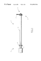
- FIG. 1 is an elevational view of a core cutting mandrel showing a core drive assembly of this invention in an operating position on the mandrel.
- FIG. 2 is a sectioned elevational view showing the relationship of the core drive components of this invention.
- FIG. 3 is a sectioned elevational view of a second preferred embodiment of this invention.
- FIG. 4 is a perspective view of the j-groove configuration of a pull rod.
- FIG. 5 is a sectioned elevational view of another embodiment of the core drive of this invention.
- unit as used herein shall be read to mean “an assembly of components that is joined together so as to become manipulatable as if it were a single component”.
- the end of the core cutter mandrel nearest the drive shall herein be called the proximal end and the end of the mandrel to receive the core drive assembly shall herein be called the distal end.
- Proportions and placements of some elements have been modified to facilitate illustration and disclosure. Some non-critical elements have been omitted or simplified to facilitate illustration and disclosure.
- Core cutter mandrel 1 has a proximal end 2 and a distal end 3 .
- Proximal end 2 typically provides the drive for the core cutter while distal end 3 is the cut-off end of the core cutter.
- Core cutter mandrels are found in a range of lengths, with mandrels of 12 feet and more not uncommon.
- the core cutting process involves the steps of; mounting an elongate tube of core stock 4 onto a mandrel 1 with the proximal end of core stock 4 supported by pusher 5 and the distal end of core stock 4 supported by core drive mechanism 6 , engaging internal core drive mechanism 6 to rotate the core stock 4 , advancing a knife 7 into core stock 4 , severing a segment of core stock 4 , disengaging core drive mechanism 6 , advancing core stock 4 the desired distance and repeating the operation.
- Internal drive core cutting mandrels typically have a central non-rotating pull rod 10 onto which a central rotating drive unit is mounted having a power input 11 at its proximal end 2 and a drive element 12 at its distal end 3 .
- the drive unit is enclosed by a non-rotating mandrel sleeve 13 .
- a set of rotating elements of a core drive mechanism was fixed to a drive element 12 and a set of non-rotating elements of a core drive mechanism was fixed to a pull rod 10 .
- the elements of the core drive unit were essentially built on to the distal end of the mandrel and were for all practical purposes a part of the mandrel construction. This method of construction necessitated the provision of a separate mandrel for each diameter of core to be cut.
- FIG. 2 will serve to illustrate the relationships between the rotating and non-rotating elements of an internal core drive mechanism and as a derivative thereof, make it apparent to one skilled in the mechanical arts, why it is seen as desirable to be able to remove and attach all of the elements of a core drive as a unit or kit.
- the rotating elements of core drive mechanism 6 are; coupling plate 14 , gripper guide 15 , grippers 16 , resilient ring 17 and cone element 18 .
- the non-rotating elements are; end cap 20 , cutting pad 21 , and quick release fastener 25 .
- pull rod 10 is inserted into drive mechanism 6 and screw heads 23 secured to drive element 12 are inserted into receivers 24 in coupling plate 14 thereby coupling core drive mechanism 6 with drive element 12 .
- Quick release fastener 25 here shown as a pin 28 having a pull ring 29 secured thereto, is then employed to secure end cap 20 to pull rod 10 as shown in FIG. 1 .
- core stock 4 is positioned for cutting by pusher 5 being advanced, pull rod 10 is drawn towards drive element 12 thereby causing cone element 18 to urge grippers 16 outward into engagement with core stock 4 .
- Core stock 4 is thereby rotated past knife 7 .
- Knife 7 is advanced towards pad 21 to cut off a core segment of the desired length.
- Pad 21 serves to back up knife 7 when it reaches the inside diameter of the core stock and thereby serves to prevent a broken or ragged inside edge on the cut off core.
- Pusher 5 of FIG. 2 is preferably made of ultra high molecular weight polyethylene (UHMWPE) which has a high lubricity and serves as a self lubricating bearing.
- Pusher 5 is provided with a magnetic element 27 which serves two functions in the configuration of FIG. 2 . First the magnet holds pusher 5 in contact with coupling plate 14 when pusher 5 is at the distal end of its travel. Pusher 5 is thereby held in place for receiving a new length of core stock 4 and pusher 5 can be detached from coupling plate 14 by pressure exerted by core stock 4 during the process of loading core stock 4 on mandrel 1 .
- UHMWPE ultra high molecular weight polyethylene
- magnetic element 27 serves to maintain pusher 5 in contact with coupling plate 14 during mounting and removing of core drive mechanism 6 , so that core drive mechanism 6 and pusher 5 can be attached to and detached from mandrel 1 as a unit or as a kit of parts.
- the quick release core drive mechanism of FIGS. 1 and 2 will serve well for internal drive core cutters for cores of relatively large diameters.
- the mechanisms of FIGS. 1 and 2 are difficult or impossible to fabricate so that they are suitable for application to cores of smaller diameters.
- the concepts of this invention serve well for core cutters for the smaller diameters of cores, but physical geometries that are better suited for use with the limitations and opportunities that are present due to the smaller diameters of cores to be cut are preferred.
- FIGS. 3 and 4 wherein a preferred embodiment suitable for use with cores of small diameters is illustrated.
- non-rotating elements are; pull rod 30 , core drive spindle 31 , end cap 32 , cutter pad 33 , and mandrel sleeve 34 .
- the rotating elements are; drive hub 35 , grippers 36 , resilient rings 37 , cone element 38 , and drive element 39 .
- the operational sequences for core cutting are the same as described above in relation to FIGS. 1 and 2.
- the distal end of pull rod 30 is provided with an axial bore 40 into which drive spindle 31 is insertable. As shown in detail in FIG. 4, the distal end of pull rod 30 is provided with j-grooves 41 into which pin 42 is insertable and then rotatable, and when released, the tension in rings 37 urges pin 42 into engagement in the terminal leg 43 of j-groove 41 thereby securing drive spindle 31 in place on the end of pull rod 30 .
- Shoulder 44 serves to maintain the elements of internal core drive assembly 50 on drive spindle 31 between shoulder 44 and end cap 32 which is secured in place on spindle 31 by means of pin 45 .
- Internal drive element 39 of mandrel 1 extends beyond mandrel sleeve 34 as shown in FIG. 3 .
- Drive hub 35 is maintained in rotational engagement with internal drive element 39 by means of translation parallel to the longitudinal axis of drive element 39 .
- Internal core drive assembly 50 is secured to the end of core cutter mandrel 1 by means of inserting the proximal end of spindle 31 into bore 40 of pull rod 30 and engaging drive hub 35 with key 46 and then pressing spindle 31 into bore 40 against the resilient resistance created by rings 37 until pin 42 reaches the bottom of j-groove 41 , and then rotating spindle 31 until pin 42 reaches the terminal leg 43 of j-groove 41 and then releasing spindle 31 so that pressures generated by rings 37 urges pin 42 into locking engagement in the terminal leg 43 of j-groove 41 .
- This mode of quick engagement and disengagement is sometimes referred to as a saber-lock coupling and is similar to that used with saber-lock flash light bulbs and sockets.
- FIG. 5 wherein another preferred embodiment of the core drive assembly of this invention is illustrated.
- Internal core drive assembly 60 is similar to that shown in FIGS. 3 and 4.
- the critical distinctions between core drive assembly 60 of FIG. 5 and core drive assembly 50 of FIG. 3 is in arrangement of the saber-lock configurations.
- core drive assembly 60 end 61 is secured to a cylindrical projection 62 of pull rod 63 .
- a tubular end 65 of spindle 66 is provided with a j-groove 64 which functions the same as j-groove 41 of FIGS. 3 and 4 to provide a means for quickly attaching and releasing core drive assembly 60 from mandrel 67 of FIG. 5 and for guiding the rotating mechanisms of core drive assembly 60 into engagement with drive hub 68 .
- this invention is for a quick attachment and release core drive assembly for internal drive core cutters.
- the quick attachment and release features of the invention involve engaging rotating elements of the drive assembly with rotating elements of a core cutter mandrel, and the engagement of non-rotating members of the drive assembly with non-rotating members of the core cutter mandrel. These engagements involve quick attachment and detachment mechanisms that are of basic constructions and typically require no tools for their employment.
Landscapes
- Life Sciences & Earth Sciences (AREA)
- Forests & Forestry (AREA)
- Engineering & Computer Science (AREA)
- Mechanical Engineering (AREA)
- Drilling Tools (AREA)
Abstract
Description
Claims (8)
Priority Applications (1)
| Application Number | Priority Date | Filing Date | Title |
|---|---|---|---|
| US08/695,213 US6293174B1 (en) | 1995-08-03 | 1996-07-29 | Quick change drive for core cutters |
Applications Claiming Priority (2)
| Application Number | Priority Date | Filing Date | Title |
|---|---|---|---|
| US187495P | 1995-08-03 | 1995-08-03 | |
| US08/695,213 US6293174B1 (en) | 1995-08-03 | 1996-07-29 | Quick change drive for core cutters |
Publications (1)
| Publication Number | Publication Date |
|---|---|
| US6293174B1 true US6293174B1 (en) | 2001-09-25 |
Family
ID=26669595
Family Applications (1)
| Application Number | Title | Priority Date | Filing Date |
|---|---|---|---|
| US08/695,213 Expired - Lifetime US6293174B1 (en) | 1995-08-03 | 1996-07-29 | Quick change drive for core cutters |
Country Status (1)
| Country | Link |
|---|---|
| US (1) | US6293174B1 (en) |
Cited By (12)
| Publication number | Priority date | Publication date | Assignee | Title |
|---|---|---|---|---|
| RU2288076C2 (en) * | 2004-03-26 | 2006-11-27 | Открытое Акционерное Общество "Корпорация Всмпо-Ависма" | Tube working method and apparatus for performing the same |
| RU2364473C1 (en) * | 2007-12-12 | 2009-08-20 | ОАО "Корпорация ВСМПО-АВИСМА" | Tooling of lathe for tube processing |
| RU2450895C2 (en) * | 2010-08-26 | 2012-05-20 | ОАО "Корпорация ВСМПО-АВИСМА" | Lathe tooling for machining tubes |
| US20140191460A1 (en) * | 2013-01-09 | 2014-07-10 | Illinois Tool Works Inc. | Pipe machining apparatuses and methods of operating the same |
| US9278417B2 (en) | 2013-01-09 | 2016-03-08 | Illinois Tool Works Inc. | Pipe machining apparatuses and methods of operating the same |
| US9399306B2 (en) | 2013-01-09 | 2016-07-26 | Illinois Tool Works Inc. | Pipe machining apparatuses and methods of operating the same |
| US9610636B2 (en) | 2013-01-09 | 2017-04-04 | Illinois Tool Works Inc. | Pipe machining apparatuses and methods of operating the same |
| US10099292B2 (en) | 2015-08-12 | 2018-10-16 | Illinois Tool Works Inc. | Crash resistant trip for a pipe machining apparatus |
| CN109249460A (en) * | 2018-09-21 | 2019-01-22 | 佛山迪骏自动化科技有限公司 | Large-bore plastics tubing disconnecting device |
| US10203030B2 (en) | 2015-07-02 | 2019-02-12 | Illinois Tool Works Inc. | Gearing arrangement |
| RU2759818C2 (en) * | 2019-08-26 | 2021-11-18 | Российская Федерация, от имени которой выступает Министерство обороны Российской Федерации | Release mandrel for correcting deformation of hole of precision thin-walled long-length pipes in the process of external processing |
| CN121132772A (en) * | 2025-08-15 | 2025-12-16 | 浙江创富新材料有限公司 | A packaging film edge cutting device |
Citations (14)
| Publication number | Priority date | Publication date | Assignee | Title |
|---|---|---|---|---|
| DE276245C (en) * | ||||
| US1012657A (en) * | 1911-06-22 | 1911-12-26 | George Kurschus | Clutch for punch-presses. |
| US1345458A (en) * | 1917-03-30 | 1920-07-06 | American Vulcanized Fibre Co | Device for cutting tubes |
| US1435511A (en) * | 1921-02-23 | 1922-11-14 | William T Sutherland | Wrist-pin wrench |
| US1736700A (en) * | 1928-02-11 | 1929-11-19 | Homer J Davis | Machine for cutting or shearing tubes |
| US2084801A (en) * | 1936-03-27 | 1937-06-22 | Hall Planetary Company | Machine tool spindle and arbor |
| US2615644A (en) * | 1950-09-12 | 1952-10-28 | Westinghouse Electric Corp | Expanding mandrel |
| US3017207A (en) * | 1958-01-20 | 1962-01-16 | Cutlas Tool And Mfg Company | Vehicle hub construction |
| US3500976A (en) * | 1967-05-23 | 1970-03-17 | Halley & Sons Ltd James | Rotary drive couplings |
| US3818797A (en) * | 1973-05-10 | 1974-06-25 | Giddings & Lewis | Drawbolt for machine tool spindles |
| US3951018A (en) * | 1974-12-06 | 1976-04-20 | Gilmore Guy T | Pipe beveling device |
| US5026223A (en) * | 1990-12-20 | 1991-06-25 | Gte Valenite Corporation | Bayonet tool locking device |
| US5458031A (en) * | 1993-11-23 | 1995-10-17 | Coiltech Corporation | Core cutter |
| US5555783A (en) * | 1994-12-19 | 1996-09-17 | Automatic Handling, Inc. | Core cutting machine having differently sized mandrels |
-
1996
- 1996-07-29 US US08/695,213 patent/US6293174B1/en not_active Expired - Lifetime
Patent Citations (14)
| Publication number | Priority date | Publication date | Assignee | Title |
|---|---|---|---|---|
| DE276245C (en) * | ||||
| US1012657A (en) * | 1911-06-22 | 1911-12-26 | George Kurschus | Clutch for punch-presses. |
| US1345458A (en) * | 1917-03-30 | 1920-07-06 | American Vulcanized Fibre Co | Device for cutting tubes |
| US1435511A (en) * | 1921-02-23 | 1922-11-14 | William T Sutherland | Wrist-pin wrench |
| US1736700A (en) * | 1928-02-11 | 1929-11-19 | Homer J Davis | Machine for cutting or shearing tubes |
| US2084801A (en) * | 1936-03-27 | 1937-06-22 | Hall Planetary Company | Machine tool spindle and arbor |
| US2615644A (en) * | 1950-09-12 | 1952-10-28 | Westinghouse Electric Corp | Expanding mandrel |
| US3017207A (en) * | 1958-01-20 | 1962-01-16 | Cutlas Tool And Mfg Company | Vehicle hub construction |
| US3500976A (en) * | 1967-05-23 | 1970-03-17 | Halley & Sons Ltd James | Rotary drive couplings |
| US3818797A (en) * | 1973-05-10 | 1974-06-25 | Giddings & Lewis | Drawbolt for machine tool spindles |
| US3951018A (en) * | 1974-12-06 | 1976-04-20 | Gilmore Guy T | Pipe beveling device |
| US5026223A (en) * | 1990-12-20 | 1991-06-25 | Gte Valenite Corporation | Bayonet tool locking device |
| US5458031A (en) * | 1993-11-23 | 1995-10-17 | Coiltech Corporation | Core cutter |
| US5555783A (en) * | 1994-12-19 | 1996-09-17 | Automatic Handling, Inc. | Core cutting machine having differently sized mandrels |
Cited By (18)
| Publication number | Priority date | Publication date | Assignee | Title |
|---|---|---|---|---|
| RU2288076C2 (en) * | 2004-03-26 | 2006-11-27 | Открытое Акционерное Общество "Корпорация Всмпо-Ависма" | Tube working method and apparatus for performing the same |
| RU2364473C1 (en) * | 2007-12-12 | 2009-08-20 | ОАО "Корпорация ВСМПО-АВИСМА" | Tooling of lathe for tube processing |
| RU2450895C2 (en) * | 2010-08-26 | 2012-05-20 | ОАО "Корпорация ВСМПО-АВИСМА" | Lathe tooling for machining tubes |
| US9962768B2 (en) | 2013-01-09 | 2018-05-08 | Illinois Took Works Inc. | Pipe machining apparatuses and methods of operating the same |
| US10328493B2 (en) * | 2013-01-09 | 2019-06-25 | Illinois Tool Works Inc. | Pipe machining apparatuses and methods of operating the same |
| US9278417B2 (en) | 2013-01-09 | 2016-03-08 | Illinois Tool Works Inc. | Pipe machining apparatuses and methods of operating the same |
| US9399306B2 (en) | 2013-01-09 | 2016-07-26 | Illinois Tool Works Inc. | Pipe machining apparatuses and methods of operating the same |
| US9610636B2 (en) | 2013-01-09 | 2017-04-04 | Illinois Tool Works Inc. | Pipe machining apparatuses and methods of operating the same |
| US20140191460A1 (en) * | 2013-01-09 | 2014-07-10 | Illinois Tool Works Inc. | Pipe machining apparatuses and methods of operating the same |
| US10029320B2 (en) | 2013-01-09 | 2018-07-24 | Illinois Tool Works Inc. | Pipe machining apparatuses and methods of operating the same |
| US10835960B2 (en) | 2013-01-09 | 2020-11-17 | Illinois Tool Works Inc. | Pipe machining apparatuses and methods of operating the same |
| US10730120B2 (en) | 2013-01-09 | 2020-08-04 | Illinois Tool Works | Pipe machining apparatuses and methods of operating the same |
| CN105026086A (en) * | 2013-01-09 | 2015-11-04 | 伊利诺斯工具制品有限公司 | Pipe processing equipment and method of operation thereof |
| US10203030B2 (en) | 2015-07-02 | 2019-02-12 | Illinois Tool Works Inc. | Gearing arrangement |
| US10099292B2 (en) | 2015-08-12 | 2018-10-16 | Illinois Tool Works Inc. | Crash resistant trip for a pipe machining apparatus |
| CN109249460A (en) * | 2018-09-21 | 2019-01-22 | 佛山迪骏自动化科技有限公司 | Large-bore plastics tubing disconnecting device |
| RU2759818C2 (en) * | 2019-08-26 | 2021-11-18 | Российская Федерация, от имени которой выступает Министерство обороны Российской Федерации | Release mandrel for correcting deformation of hole of precision thin-walled long-length pipes in the process of external processing |
| CN121132772A (en) * | 2025-08-15 | 2025-12-16 | 浙江创富新材料有限公司 | A packaging film edge cutting device |
Similar Documents
| Publication | Publication Date | Title |
|---|---|---|
| US6293174B1 (en) | Quick change drive for core cutters | |
| US5928241A (en) | Quick connection method and device, and surgical instrument for driving interchangeable rotary tools | |
| US5813802A (en) | Drilling tool assembly and its center drill and cup shape drill | |
| US4395051A (en) | Quick-change holder | |
| US5033180A (en) | Bearing puller | |
| KR20100137500A (en) | Quick change shafts, hole cutters, and methods | |
| JP3318732B2 (en) | Spindle parts clamping device | |
| JP2016114243A (en) | Winding shaft, and method of inserting winding shaft to winding device | |
| GB2203364A (en) | Nose piece adaptor for manual or power feed drill | |
| US3971526A (en) | Textile spool | |
| US5265990A (en) | Short toolholder system | |
| US4067403A (en) | Wire driver handpiece | |
| CA2813602C (en) | Ring lock mandrel and release mechanism | |
| CN110759181B (en) | Adhesive tape roll fixing device | |
| US5868400A (en) | Push type expanding mandrel apparatus | |
| US3765074A (en) | Sleeve holder for tools | |
| JPH091407A (en) | Device for clamping tool holder taper of various sizes to spindle | |
| US5325749A (en) | Machine tool having a quick release draw tube and jaw chuck adapter | |
| US4939834A (en) | Machine tool with tool change mechanism | |
| AU1901792A (en) | Fastening device for milling tools and the like, adaptable for various holder sizes | |
| JPH01190237A (en) | Armature winder with quick changeable tool | |
| JP3563795B2 (en) | Roll-shaped recording paper and a movable flange rotatably supporting the roll-shaped recording paper | |
| JP2003182890A (en) | Clamp mechanism and rewinding shaft using this clamp mechanism | |
| US2694332A (en) | Hose-nipple assembling tool having floating mandrel | |
| JP2002012345A (en) | Core fixing device |
Legal Events
| Date | Code | Title | Description |
|---|---|---|---|
| AS | Assignment |
Owner name: PRODUCTIVE SOLUTIONS, INC., WISCONSIN Free format text: ASSIGNMENT OF ASSIGNORS INTEREST;ASSIGNOR:RULSEH, TIM;REEL/FRAME:008176/0232 Effective date: 19960729 |
|
| STCF | Information on status: patent grant |
Free format text: PATENTED CASE |
|
| REMI | Maintenance fee reminder mailed | ||
| FPAY | Fee payment |
Year of fee payment: 4 |
|
| SULP | Surcharge for late payment | ||
| FPAY | Fee payment |
Year of fee payment: 8 |
|
| FPAY | Fee payment |
Year of fee payment: 12 |
|
| AS | Assignment |
Owner name: DOUBLE E COMPANY, LLC, MASSACHUSETTS Free format text: ASSIGNMENT OF ASSIGNORS INTEREST;ASSIGNOR:PRODUCTIVE SOLUTIONS, INC. D/B/A APPLETON MFG. DIVISION;REEL/FRAME:039384/0772 Effective date: 20160809 |
|
| AS | Assignment |
Owner name: TWIN BROOK CAPITAL PARTNERS, LLC, AS AGENT, ILLINO Free format text: SECURITY INTEREST;ASSIGNOR:DOUBLE E COMPANY, LLC;REEL/FRAME:039409/0758 Effective date: 20150605 |
|
| AS | Assignment |
Owner name: TWIN BROOK CAPITAL PARTNERS, LLC, AS AGENT, ILLINO Free format text: CORRECTIVE ASSIGNMENT TO CORRECT THE EXECUTION DATE FROM 6/5/15 TO 8/9/16. PREVIOUSLY RECORDED ON REEL 039409 FRAME 0758. ASSIGNOR(S) HEREBY CONFIRMS THE SECURITY INTEREST;ASSIGNOR:DOUBLE E COMPANY, LLC;REEL/FRAME:039669/0046 Effective date: 20160809 |
|
| AS | Assignment |
Owner name: TWIN BROOK CAPITAL PARTNERS, LLC, AS AGENT, ILLINO Free format text: SECURITY INTEREST;ASSIGNOR:DOUBLE E COMPANY, LLC;REEL/FRAME:042548/0757 Effective date: 20170531 |
|
| AS | Assignment |
Owner name: DOUBLE E COMPANY, LLC, MASSACHUSETTS Free format text: RELEASE BY SECURED PARTY;ASSIGNOR:TWIN BROOK CAPITAL PARTNERS, LLC, AS AGENT;REEL/FRAME:042565/0799 Effective date: 20170531 |