US6283632B1 - Method of measuring temperature - Google Patents
Method of measuring temperature Download PDFInfo
- Publication number
- US6283632B1 US6283632B1 US09/455,165 US45516599A US6283632B1 US 6283632 B1 US6283632 B1 US 6283632B1 US 45516599 A US45516599 A US 45516599A US 6283632 B1 US6283632 B1 US 6283632B1
- Authority
- US
- United States
- Prior art keywords
- light
- temperature
- sensor
- transducer
- source
- Prior art date
- Legal status (The legal status is an assumption and is not a legal conclusion. Google has not performed a legal analysis and makes no representation as to the accuracy of the status listed.)
- Expired - Lifetime
Links
Images


Classifications
-
- G—PHYSICS
- G01—MEASURING; TESTING
- G01K—MEASURING TEMPERATURE; MEASURING QUANTITY OF HEAT; THERMALLY-SENSITIVE ELEMENTS NOT OTHERWISE PROVIDED FOR
- G01K11/00—Measuring temperature based upon physical or chemical changes not covered by groups G01K3/00, G01K5/00, G01K7/00 or G01K9/00
- G01K11/32—Measuring temperature based upon physical or chemical changes not covered by groups G01K3/00, G01K5/00, G01K7/00 or G01K9/00 using changes in transmittance, scattering or luminescence in optical fibres
- G01K11/3206—Measuring temperature based upon physical or chemical changes not covered by groups G01K3/00, G01K5/00, G01K7/00 or G01K9/00 using changes in transmittance, scattering or luminescence in optical fibres at discrete locations in the fibre, e.g. using Bragg scattering
-
- G—PHYSICS
- G01—MEASURING; TESTING
- G01K—MEASURING TEMPERATURE; MEASURING QUANTITY OF HEAT; THERMALLY-SENSITIVE ELEMENTS NOT OTHERWISE PROVIDED FOR
- G01K11/00—Measuring temperature based upon physical or chemical changes not covered by groups G01K3/00, G01K5/00, G01K7/00 or G01K9/00
- G01K11/12—Measuring temperature based upon physical or chemical changes not covered by groups G01K3/00, G01K5/00, G01K7/00 or G01K9/00 using changes in colour, translucency or reflectance
- G01K11/18—Measuring temperature based upon physical or chemical changes not covered by groups G01K3/00, G01K5/00, G01K7/00 or G01K9/00 using changes in colour, translucency or reflectance of materials which change translucency
Definitions
- the present invention relates to a temperature sensor for medical applications, a method of making the same, and a method of measuring temperature.
- thermometers For use in a microwave hyperthermia therapy against cancers, various thermometers have been used employing an optical fiber for measuring the temperature at local portions of a body. Optical thermometers have been used for the reasons that correct measurement is obtained without interference from electromagnetic waves and no electric shock is given to the living body. It is desired to use the optical thermometer not only for the hyperthermia apparatus but also for extracorporeal blood circulation instruments such as an artificial heart-lung device or an artificial dialysis device, as well as for probing the blood during cardiac catheterization, since it is capable of reducing the danger of electric shock.
- a first system is a sensor using a semiconductor as a transducer. That is, the semiconductor usually exhibits an energy gap that varies depending upon a change in the temperature and, hence, exhibits an optical absorption and an accompanying light transmission spectrum that changes thereto. Therefore, there has been proposed an optical fiber sensor by utilizing such properties (see, for example, Japanese Unexamined Patent Publication (Kokai) No. 62-85832). For example, InGaAs and GaAs may be used as semiconductors.
- FIG. 9 (A) shows an example of the constitution of a temperature sensor using such a semiconductor.
- a sensor 11 composed of the above semiconductor is fixedly provided to an end of optical fiber 10 on the side closer to a body that is to be measured, and a suitable reflector plate 12 is brought into contact with the sensor.
- Light having a suitable wavelength is permitted to be incident (L IN )on the other end of the optical fiber: the incident light is reflected by the reflector plate 12 via the semiconductor sensor 11 and returns back to the incident end passing through the semiconductor sensor 11 again.
- the intensity of light at this moment is measured to determined the temperature of the body that is being measured.
- FIG. 9 (B) shows a relationship between the wavelength of light in the semiconductor and the transmittance factor for a semiconductor sensor having a thickness of 250 ⁇ m, from which it will be understood that the transmittance changes depending upon the temperature.
- a second method is a sensor utilizing a change in the refractive index of a cladding material.
- a temperature sensor in which, as shown in FIG. 10 (A), a cladding 13 is removed from the end of the optical fiber 10 , and a cavity 15 containing glycerine 14 therein, is formed at this portion (see, for example, Japanese Unexamined Patent Publication (Kokai) No. 59-160729).
- the refractive index of the glycerine 14 changes depending upon the temperature and, hence, the angle of reflection of light changes on the interface between the core 16 and the cladding 13 .
- the intensity of light returning i.e., reflected by the reflector plate 12
- Measuring the quantity of light that has returned makes it possible to measure the temperature.
- the DC voltage that is converted through the sensor from the quantity of returned light undergoes a change depending upon a change in the temperature. Therefore, measurement of the DC voltage makes it possible to measure the temperature of the material being measured. In the sensor of this type, however, the end of the probe has insufficient strength. Moreover, it is difficult to fabricate the probe in a small size.
- a third system is a sensor which utilizes a change in the color of liquid crystals.
- this system which utilizes a change in the color of liquid crystals depending upon the temperature, there is proposed a sensor obtained by fastening a cavity 15 made of a very narrow glass tube containing liquid crystals 17 at the end of the optical fiber 10 (see, for example, Japanese Unexamined Patent Publication (Kokai) No. 57-63430).
- FIG. 11 is a diagram illustrating its principle.
- FIG. 11 shows a temperature sensor according to the above-mentioned third system, wherein a cavity 15 containing liquid crystals 17 is placed near the material that is to be measured, and an optical fiber 10 is connected to the cavity 15 .
- An example consists of permitting the light to be input at a free end of the optical fiber 10 , and measuring the light reflected by the liquid crystals, in order to calculate the temperature of the material that is being measured. That is, the principle is utilized that the color of the liquid crystals change depending upon the temperature, thus the reflection factor of the incident light changes.
- the optical fiber 10 for incident light may be provided separately from the optical fiber 10 ′ for measuring the reflected light.
- the optical fibers are used in a bundled form in which both optical fibers are bundled together.
- a fourth system is a sensor which utilizes a change in the intensity of a fluorescent material. That is, the wavelength of fluorescence of some fluorescent materials is shifted depending upon the temperature.
- the temperature sensor of this system utilizes this property.
- FIGS. 12A, 12 B, and 12 C illustrate the principle of this system.
- FIG. 12 (A) shows that the fluorescence spectrum undergoes a change in intensity and wavelength depending upon the temperature of the sensor (here, it is presumed that the temperatures T 1 , T 2 , and T 3 have a relationship T 1 ⁇ T 2 ⁇ T 3 ).
- Curve “C” represents the spectrum of the excitation light.
- Curves D, E, and F represent the fluorescence spectrum of the material at temperatures T 1 , T 2 and T 3 respectively.
- the fluorescent material having such properties may be GaAs/AlGaAs produced by Asea Co. or an inorganic fluorescent material produced by Luxtron Co. or Omron Co., and can be used as a temperature sensor.
- FIG. 12B further illustrates such a sensor, wherein an optical fiber 10 is connected to a sensor 84 (shown in FIG. 12C) and a measuring device 80 .
- the measuring device 80 comprises a light source 81 (e.g., a light emitting diode), a temperature analyzing portion 82 , and a photodiode 83 .
- the sensor 84 comprises layers of GaAs 85 and AlGaAs 86 .
- the present invention provides a small sized temperature sensor for medical application for measuring local temperatures in the body and for measuring temperatures in an extracorporeal blood circulation circuit, which reduces the possibility of electric shock to the living body and features reduced cost, and increased resolution and reliability.
- the present invention further provides a method of measuring temperature including the steps of calibrating a sensor having a source of light which irradiates light, an optical fiber positioned at one end to receive light from the source of light, a transducer positioned near the other end of the optical fiber, the transducer being made up of at least two polymers that have dissimilar temperature dependencies of refractive index and form a microphase separation structure, a reflection means for reflecting the irradiated light, and an arithmetic processing unit which receives the reflected light by exposing the sensor to two or more sources of heat whose values are known; and, exposing the sensor to a portion whose temperature is to be measured.
- FIG. 1 is a block diagram illustrating the construction of a temperature sensor for medical application according to the present invention.
- FIG. 2 is a block diagram illustrating another construction of the temperature sensor for medical application according to the present invention.
- FIGS. 3 and 3A are diagrams for explaining a first embodiment of the temperature sensor medical application according to the present invention.
- FIG. 4 is a diagram for explaining a second embodiment of the temperature sensor for medical application according to the present invention.
- FIGS. 5A and 5B are diagrams explaining the construction of a polymer according to the present invention.
- FIGS. 6 and 6A are diagrams for explaining a third embodiment of the temperature sensor for medical application according to the present invention.
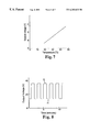
- FIG. 7 is a diagram showing a calibration curve of the temperature sensor for medical application according to the present invention.
- FIG. 8 is a diagram illustrating a temperature response curve of the temperature sensor according to the third embodiment of the present invention.
- FIGS. 9A and 9B are diagrams illustrating construction of a temperature sensor unit in a conventional temperature sensor for medical application.
- FIGS. 10A and 10B are diagrams illustrating another construction of the temperature sensor unit in a conventional temperature sensor for medical application.
- FIG. 11 is a diagram illustrating a further construction of the temperature sensor unit in a conventional temperature sensor for medical application.
- FIGS. 12A, 12 B, and 12 C are diagrams illustrating a yet further construction of the temperature sensor unit in a conventional temperature sensor for medical application.
- FIG. 13 is a graph showing relationships between the refractive indexes and the temperature dependencies of an epoxy resin (ERL 4221 ) which is a base phase-forming resin and an acrylic resin (M 113 ) which is a domain phase-forming resin.
- ERP 4221 an epoxy resin
- M 113 an acrylic resin
- FIG. 14 is a diagram showing a relationship between the transmittance factor and the temperature dependency of a polymer of the micro phase separation structure comprising the epoxy resin and the acrylic resin.
- the object of the present invention is to provide a temperature sensor for medical applications such as measuring local temperature in the body or for measuring the temperature in the extracorporeal blood circulation circuit, which temperature sensor reduces the possibility of electric shock to the living body, is disposable, and features high resolution, high reliability and small size.
- the present invention employs the technical construction that is described below. More specifically, the invention relates to a temperature sensor for medical application which, at the time of measuring the temperature at a local portion of the human body, reduces the possibility of electric shock to the living body owing to the use of an optical means, and which features good precision and is disposable. That is, the invention relates to a temperature sensor for medical application comprising: a source of light; an optical fiber positioned at one end to receive light from said light source; a transducer near the other end of the optical fiber, said transducer being made up of at least two polymers that have dissimilar or different temperature dependencies of refractive index, a point of equal refractive index which is lower than 25° C. or higher than 45° C., and a microphase separation structure; a reflection means for reflecting the irradiated light; and an arithmetic processing unit which receives the reflected light and calculates the temperature of the portion to be measured.
- the polymers have refractive indices that can be measured by using an ordinary refractive index meter, and should have temperature dependencies that are different over a temperature range from 25 to 45° C. which corresponds to the temperature of a living body of a human being.
- Suitable polymers for use in the transducer of the present invention have a difference in refractive indexes greater than 0.0001 over the above-mentioned temperature range.
- Preferred polymers for use in the present invention have a difference in refractive index greater than 0.001.
- the point of equal refractive index is specified to be lower than 25° C. or higher than 45° C. This is because, the above temperature range is the one in which the temperature sensors for medical applications are used, and the temperature may not be exclusively determined if the point of equal refractive index resides within that range.
- the two or more polymers are specified to have a microphase separation structure. This is because, in the case of complete phase separation, handling becomes difficult and the measurement of temperature becomes incorrect. When the polymers are completely compatible, on the other hand, only one refractive index is exhibited and the light transmission factor no longer changes depending upon the temperature.
- microphase separation structure employed in the present invention refers to the condition where two or more polymers are phase-separated on the molecular level, or refers to the condition of a called “sea-island” structure.
- the temperature sensor for medical applications employs the aforementioned technical construction. Namely, the temperature sensor causes the light transmission factor to change depending upon a change in the temperature, the temperature sensor being constituted of polymers which are provided in contact with a portion of which the temperature is to be measured or which are provided near the portion of which the temperature is to be measured. The intensity of light incident through the optical fiber is compared with the intensity of light that has passed through the polymer, and a change therebetween is detected in order to measure the temperature of the portion that is being measured.
- a light reflection means consisting of a suitable reflector plate is fitted to the polymers as an integrated structure, the light incident through the optical fiber is reflected by the light reflection means via the polymers and is then passed through the polymers again, and the reflected light is measured in order to measure the temperature of the portion being measured.
- FIG. 1 is a diagram illustrating the components of an embodiment of the temperature sensor for medical application according to the present invention, which comprises a source of light 1 for irradiating light, an optical fiber 10 arranged between the portion 2 to be measured and the source of light 1 , an arithmetic processing unit 3 which calculates the temperature of the portion 2 to be measured by receiving the reflected light from the end of the optical fiber which is close to the portion 2 to be measured, a polymer 5 which is provided at an end of the optical fiber 10 close to the portion 2 that is to be measured and of which the light transmittance changes depending upon the temperature, and a reflection means 6 . It is desired that the arithmetic processing unit 3 in the present invention is provided with a light sensor 4 .
- the polymer 5 is constituted integrally with a light reflection means 6 which may be any suitable light reflector plate or the like. It is desired that the light incident from a suitable source of light 1 pass through the optical fiber, be reflected by the light reflection means 6 , and is returned back through the optical fiber to the arithmetic process unit 3 which executes a predetermined arithmetic process to calculate the temperature of the portion being measured.
- a light reflection means 6 which may be any suitable light reflector plate or the like. It is desired that the light incident from a suitable source of light 1 pass through the optical fiber, be reflected by the light reflection means 6 , and is returned back through the optical fiber to the arithmetic process unit 3 which executes a predetermined arithmetic process to calculate the temperature of the portion being measured.
- an optical transducer 20 (comprising the polymer 5 and the light reflection means 6 ) employed in the temperature sensor for medical applications, may either be fastened as shown in FIG. 1 to the end of the optical fiber close to the portion 2 to be measured or be placed as shown in FIG. 2 near the end of the optical fiber but being separate therefrom.
- the temperature sensor unit 25 employs an optical transducer 20 which comprises the polymer 5 of which the light transmittance changes depending upon the temperature. Furthermore, a suitable light reflection means 6 is fitted to the polymer 5 as a unitary structure, and the reflection factor of light going out of the temperature sensor unit 25 after the light has fallen on and been reflected by the temperature sensor unit 25 changes depending upon the temperature of the portion 2 (not shown) to be measured.
- FIG. 5 (A) shows the mode of operation of the polymer 5 used for the optical transducer 20 .
- the polymer 5 is obtained by curing a mixture of, for example, two or more kinds of polymerizable compounds (having different refractive indices when cured) and a suitable curing agent or agents.
- the polymer 5 possesses a domain phase structure n, of greater than 1 ⁇ m due to phase separation during the curing.
- the domain phase n 1 and the base phase n 2 have dissimilar refractive indexes and dissimilar temperature dependencies thereof.
- the difference in the refractive index changes (e.g., increases) as a function of temperature, and scattering of light due to the domain phase changes causing the light transmittance of the cured product to change (e.g., decrease).
- the length of the domain phase structure n is greater than the wavelength of light emitted by the light source.
- the temperature of equal refraction index be at least lower than the body temperature or be higher than 45° C.
- the optical transducer 20 can be used for the measurement of temperatures.
- a reflector plate 6 should be attached to one surface thereof as shown in FIG. 5 (B) to facilitate measurement of the reflected light.
- the reflector plate 6 may be formed by depositing or adhering a thin metal film such as silver, aluminum or gold. Then, a change in the temperature can be detected as a change in the refractive index. This is found according to Rayleigh-Gans-Debye's equation shown below.
- the temperature sensor for medical application measures temperatures over a range of from 25° C. to 45 C.
- a material having such sensitivity and linearity, curing conditions, thickness and wavelength should be determined as to obtain a resolution of 0.1° C. over this range.
- a difference in the refractive index should be greater than 1 ⁇ 10 ⁇ 4 .
- Suitable polymers 5 used for the present invention include a cured product obtained by blending, for example,
- Suitable cationically polymerizable compounds (1) include alicylic, aliphatic and aromatic epoxy resins or the like. Preferred cationically polymerizable compounds include aromatic epoxy resins.
- Suitable radically polymerizable compounds (2) include acrylic or methacrylic monomers, oligomers or the like.
- Suitable initiator compounds (3) and (4) may be either those of the heat polymerizable type or the right polymerizable type. Desirably, however, compound (3) should be a heat polymerizable cationic polymerization initiator and compound (4) should be a light polymerizable radical polymerization initiator.
- thermometer using the above optical transducer 20 is constituted, as shown in FIGS. 1 and 2, of a temperature probe or a temperature cell made up of an optical fiber, a polymer and a reflector plate and a source of light and an arithmetic processing unit which includes a light sensor. As required, furthermore, there may be provided a display device 21 as illustrated in FIGS. 1 and 2.
- the temperature sensors of the types shown in FIGS. 1 and 2 can be used as described below. That is, the temperature sensor of the probe type shown in FIG. 1 in which the optical transducer 20 is mounted on a single fiber having a small diameter, is used for the measurement of local temperatures in the living body, and the temperature sensor of the type shown in FIG. 2 in which a cell with a transducer is separately provided and being connected with a bundled fiber, is used for the measurement of temperatures in the extracorporeal circulation circuit.
- the optical fiber 10 used in the present invention may either be a bundled fiber or a single fiber.
- the bundled fiber is branched into two on one end and to which are connected the source of light 1 and the light sensor 4 .
- the single fiber there may be separately provided a beam splitter or a light coupler to guide the light returned from the optical transducer 20 to the light sensor.
- the source of light 1 there can be used a light emitting diode (LED), a semiconductor laser (LD), a xenon lamp, a halogen lamp or the like.
- the lightsensor 4 there can be used a photodiode, a photomultiplier, comprising CdS or the like.
- the temperature is calibrated by utilizing two or more sources of heat whose values have been known.
- the temperature sensor is calibrated by immersing the sensor in sterilized water maintained at, for example, 30° C. and 40° C.
- the calibration is effected by circulating sterilized water having a similar temperature.
- the polymer 5 comprises an epoxy resin and an acrylic resin and. can be used as a material that exhibits the aforementioned properties. Namely, a cured material comprising a blend as shown in Table 1 can be used as the polymer 5 and exhibits a linear response when adapted to measuring the body temperature over a given range.
- the curing consists of irradiation with ultraviolet rays of about 30.5 mW/cm 2 intensity and a heat treatment of 120° C. for 1 hour and then 150° C. for an additional 1 hour.
- a temperature probe that uses the above material (2 mm in thickness) exhibits a sensitivity of ⁇ 0.048 V/° C., a resolution of ⁇ 0.021° C./mV, and a linear response between 25° C. and 45° C.
- Blending of a polymer that exhibits high sensitivity and a curing method have been developed.
- Table 2 shows an example of blending.
- the curing consists of first irradiating the blend with ultraviolet rays of 30.5 mW/cm 2 for five minutes and then heat treating the blend at 100° C. for 1 hour, then 150° C. for 1 hour, and then 200° C. for a final hour.
- the highly sensitive polymer was prepared by increasing the content of acrylic resin, selectively polymerizing the acrylic domain by using a light-curing agent, and then heat-polymerizing the epoxy phase after the acrylic domain has been formed. This makes it possible to obtain a “sea-island” type structure having a large phase separation factor.
- phase having different refractive indices exhibit increased light scattering, making it possible to obtain a transducer that features high sensitivity.
- a transducer which is 0.25 mm thick exhibits a sensitivity of ⁇ 0.039 V/° C., a resolution of ⁇ 0.026° C/mV, and a linear response between 25° C. and 60° C.
- FIG. 13 shows the relationship between refractive index and temperature of an epoxy resin (ERL 4221) which is a base phase-forming resin and of an acrylic resin (M 113) which is a domain phase-forming resin.
- ERP 4221 an epoxy resin
- M 113 an acrylic resin
- Line “I” shows a change in the refractive index n 2 of the epoxy resin (ERL 4221) depending upon the temperature.
- Line “J” shows a change in the refractive index n 1 of the acrylic resin (M-113) depending upon the temperature.
- FIG. 14 shows the relationship between the light transmittance factor and temperature of the microphase separation structure comprising the epoxy resin and the acrylic resin and having a mixing ratio as shown in Table 1.
- the ordinate of FIG. 14 represents the measured ratio I t /I o .
- a light I o is incident on the other surface thereof and a light I t that is reflected is output from the polymer.
- the light used for the measurement has a transmitted wavelength of 632 nm.
- the transmittance factor of the polymer abruptly drops with a rise in the temperature.
- the transmittance factor nearly linearly drops from a temperature of 32° C. to 50° C., which makes it possible to obtain a high resolution in measuring the temperature of the human body and the temperature of the blood, and, hence, makes it possible to correctly measure the temperature in such fields and to provide a device that is adapted to measuring the temperature in such fields.
- the present inventors have studied a change in the transmittance factor that varies depending upon the temperature and have discovered that when the wavelength of light was fixed at 850 nm and the thickness of the sensor plate made of the polymer was set to 2 mm, the factor was maintained at a sufficiently high level when the diameter of domain particles was changed, for example, from 1 ⁇ m to 10 ⁇ m.
- the diameter of domain particles was set at the higher side of the range and thus the sensitivity was improved, since the transmittance increases with an increase in the diameter of the domain particles.
- the diameter of the domain particles was adjusted to be, for example, 2 ⁇ m and when the thickness of the polymer plate was changed from 0.5 mm to 4 mm, it was found that the sensitivity deteriorated as the plate thickness was decreased.
- the thickness of the polymer plate was set to 2 mm, and when the wavelength of light was changed from 400 nm to 1000 nm, it was found that the sensitivity was improved with a decrease in the wavelength.
- a temperature probe was prepared by attaching a temperature transducer 20 made of the polymer 5 to a non-branched portion 25 of a two-branched random bundled fiber 10 using a transparent adhesive agent as shown in FIGS. 3 and 3A.
- a silver-deposited film 6 was stuck to the transducer 20 of a thickness of 0.25 mm at the end of the probe to form a reflector plate, and a black paint 26 was applied around it to shield external light (as shown in FIG. 3 A).
- the source of light 1 was a semiconductor laser having a wavelength of 670 nm, and the light was permitted input to the end 31 of the branched fiber through a collimator lens 30 .
- the light reflected by the transducer unit 20 was taken out through another end 32 of the fiber and was measured for its intensity by using a light-receiving element 4 which consists of, for example, a silicon photodiode.
- the output signal was displayed as a voltage through a preamplifier 33 and a digital voltmeter 34 and was also displayed on a recording meter 35 .
- the probe exhibited a sensitivity of ⁇ 0.039 V/° C., a resolution of ⁇ 0.026° C./mV, a linear response between 25° C. and 60° C., and a 95% response time of 30 seconds/70° C.
- a temperature sensor was prepared having a structure as shown in FIG. 4 . That is, the transducer 20 consisting of the polymer 5 was not directly attached to the optical fiber 10 but was mounted on the measuring portion 2 and, then, the optical fiber 10 was fitted thereto to measure the temperature.
- the polymer 5 was adhered to the inside of the blood flow cell 40 which is made of, for example, a transparent polycarbonate and, then, a silver-deposited film 6 was adhered to form a reflector plate.
- the bundled fiber 10 for measurement can be fastened to the back side of the transducer 20 in the flow cell 40 maintaining a predetermined gap.
- a fastening fitting 41 also works to shield the external light falling on the cell 40 .
- the flow cell 40 is disposable but must be calibrated before being used.
- the calibration instrument comprises a temperature controller, a standard temperature probe, and a sterilized water circulation circuit, and to which the cell is connected and is calibrated using two different temperatures. After calibration, the flow cell is connected to the blood circuit to take measurements.
- the temperature transducer is used not only as a single-function sensor but also as one function of a cell which is equipped with other sensors.
- the flow cell 40 may be connected to a vinyl tube 42 or the like and the sensor unit covered with a light-shielding cover 43 that is separately formed.
- This embodiment is adapted to be used as a cell for measuring the temperature of an extracorporeal circulation circuit.
- the temperature sensor has a construction suited for being used as a temperature probe having a small diameter for measuring the temperature of the hyperthermia therapy or for measuring local temperatures.
- the diameter is smaller than 1 mm.
- the fiber 10 comprises a quartz core, a polymer cladding and a jacket of a fluorine-containing resin.
- a transducer 25 was formed at one end 61 of the fiber 10 and a photocoupler 63 was attached at the other end 62 . As shown in FIG.
- the polymer 5 having a liquid form, was poured into the fiber hole of a jacket 64 , and the other end of the fiber was irradiated with ultraviolet rays using a collimator to form the acrylic domain, and then the epoxy phase was cured by heating.
- the cured polymer 5 was smoothly cut at a length of 0.25 mm to 0.5 mm beyond the end of the fiber in parallel with the end surface thereof, and a silver deposited film was adhered onto the cut surface to form a reflector plate 6 .
- the cut surface may be directly coated with silver by, for example, vacuum vaporization.
- a black paint 65 was applied to the end to shield the external light.
- a light source unit 66 consisting of a light-emitting diode (LED) having a wavelength of 660 nm and a monitor sensor was employed, and the light produced was permitted to fall on the optical fiber 10 by using a collimator.
- LED light-emitting diode
- FIG. 7 shows a calibration curve of the temperature probe.
- the sensitivity was ⁇ 0.077 V/° C.
- the resolution was ⁇ 0.013° C./mV
- the probe had a linear response between 22° C. and 45° C.
- FIG. 8 shows a temperature response curve of the sensor of this embodiment. The response time was about 10 seconds when the sensor was moved from a 6° C. environment (shown as the voltage plateau “G”) to a 75° C. environment (shown as the voltage plateau “H”).
Priority Applications (1)
| Application Number | Priority Date | Filing Date | Title |
|---|---|---|---|
| US09/455,165 US6283632B1 (en) | 1992-11-25 | 1999-12-06 | Method of measuring temperature |
Applications Claiming Priority (4)
| Application Number | Priority Date | Filing Date | Title |
|---|---|---|---|
| JP31485292A JP3375995B2 (ja) | 1992-11-25 | 1992-11-25 | 医療用温度センサ |
| JP4-314852 | 1992-11-25 | ||
| US09/002,587 US6019507A (en) | 1992-11-25 | 1998-01-05 | Method of making temperature sensor for medical application |
| US09/455,165 US6283632B1 (en) | 1992-11-25 | 1999-12-06 | Method of measuring temperature |
Related Parent Applications (1)
| Application Number | Title | Priority Date | Filing Date |
|---|---|---|---|
| US09/002,587 Division US6019507A (en) | 1992-11-25 | 1998-01-05 | Method of making temperature sensor for medical application |
Publications (1)
| Publication Number | Publication Date |
|---|---|
| US6283632B1 true US6283632B1 (en) | 2001-09-04 |
Family
ID=18058391
Family Applications (2)
| Application Number | Title | Priority Date | Filing Date |
|---|---|---|---|
| US09/002,587 Expired - Lifetime US6019507A (en) | 1992-11-25 | 1998-01-05 | Method of making temperature sensor for medical application |
| US09/455,165 Expired - Lifetime US6283632B1 (en) | 1992-11-25 | 1999-12-06 | Method of measuring temperature |
Family Applications Before (1)
| Application Number | Title | Priority Date | Filing Date |
|---|---|---|---|
| US09/002,587 Expired - Lifetime US6019507A (en) | 1992-11-25 | 1998-01-05 | Method of making temperature sensor for medical application |
Country Status (5)
Cited By (33)
| Publication number | Priority date | Publication date | Assignee | Title |
|---|---|---|---|---|
| US20020138107A1 (en) * | 2001-02-20 | 2002-09-26 | Weiner Michael L. | Electromagnetic interference immune tissue invasive system |
| US6513972B1 (en) * | 2000-08-31 | 2003-02-04 | Siemens Westinghouse Power Corporation | Optical temperature probe, monitoring system, and related methods |
| US6599442B2 (en) * | 2000-02-29 | 2003-07-29 | Polytechnic University | Temperature measurement and temperature controlled switching based on helical sense dependent liquid crystal phases |
| US20040165646A1 (en) * | 2003-02-20 | 2004-08-26 | Shidemantle Jack P. | Digitally modified resistive output for a temperature sensor |
| US20040252748A1 (en) * | 2003-06-13 | 2004-12-16 | Gleitman Daniel D. | Fiber optic sensing systems and methods |
| US20050094704A1 (en) * | 2001-12-28 | 2005-05-05 | Giorgio De Cicco | Non-invasive device for measuring blood temperature in a circuit for the extracorporeal circulation of blood, and equipment provided with this device |
| US20050131305A1 (en) * | 2002-05-17 | 2005-06-16 | Danielson Bo G. | Sensor unit and method for sensing a blood related parameter and system including such a sensor unit |
| US20060176930A1 (en) * | 2005-02-07 | 2006-08-10 | Yoo Jung Y | Method for measuring temperature in microscale |
| US20070081294A1 (en) * | 2005-10-11 | 2007-04-12 | Applied Materials, Inc. | Capacitively coupled plasma reactor having very agile wafer temperature control |
| US20070081296A1 (en) * | 2005-10-11 | 2007-04-12 | Applied Materials, Inc. | Method of operating a capacitively coupled plasma reactor with dual temperature control loops |
| US20070081295A1 (en) * | 2005-10-11 | 2007-04-12 | Applied Materials, Inc. | Capacitively coupled plasma reactor having a cooled/heated wafer support with uniform temperature distribution |
| US20070091538A1 (en) * | 2005-10-20 | 2007-04-26 | Buchberger Douglas A Jr | Plasma reactor with wafer backside thermal loop, two-phase internal pedestal thermal loop and a control processor governing both loops |
| US20070097580A1 (en) * | 2005-10-11 | 2007-05-03 | Applied Materials, Inc. | Method of cooling a wafer support at a uniform temperature in a capacitively coupled plasma reactor |
| US20080117951A1 (en) * | 2006-11-16 | 2008-05-22 | University Of South Florida | Thermally Compensated Dual-Probe Fluorescence Decay Rate Temperature Sensor and Method of Use |
| US20080144698A1 (en) * | 2006-12-19 | 2008-06-19 | Mathieu Cloutier | Fiber optic temperature sensor |
| US20090135880A1 (en) * | 2007-11-22 | 2009-05-28 | Yamatake Corporation | Temperature sensor probe and manufacturing method of the same |
| US20090296778A1 (en) * | 2008-05-27 | 2009-12-03 | Yamatake Corporation | Fluorescent temperature sensor |
| US20100140233A1 (en) * | 2002-06-18 | 2010-06-10 | Hamamatsu Photonics | Laser processing apparatus,laser processing temperature measuring apparatus,laser processing method,and laser processing temperature measuring method |
| US20100268113A1 (en) * | 2009-04-15 | 2010-10-21 | Arizant Healthcare Inc. | Deep tissue temperature probe constructions |
| US20100268114A1 (en) * | 2009-04-15 | 2010-10-21 | Arizant Healthcare Inc. | Deep tissue temperature probe constructions |
| CN101569523B (zh) * | 2009-04-30 | 2011-02-02 | 上海大学 | 激光诱导间质热疗中分布温度实时测量系统及数据处理方法 |
| US20110051776A1 (en) * | 2009-08-31 | 2011-03-03 | Arizant Healthcare Inc. | Flexible deep tissue temperature measurement devices |
| US20110268150A1 (en) * | 2010-12-17 | 2011-11-03 | General Electric Company | System and method for measuring temperature |
| CN101421600B (zh) * | 2006-04-11 | 2011-11-30 | 萨索特兰公司 | 用于校准分布式纤维温度感测系统的方法和装置 |
| US8292502B2 (en) | 2010-04-07 | 2012-10-23 | Arizant Healthcare Inc. | Constructions for zero-heat-flux, deep tissue temperature measurement devices |
| US8292495B2 (en) | 2010-04-07 | 2012-10-23 | Arizant Healthcare Inc. | Zero-heat-flux, deep tissue temperature measurement devices with thermal sensor calibration |
| US9354122B2 (en) | 2011-05-10 | 2016-05-31 | 3M Innovative Properties Company | Zero-heat-flux, deep tissue temperature measurement system |
| CN106814013A (zh) * | 2017-01-19 | 2017-06-09 | 国家纳米科学中心 | 一种基于光谱浊度原位测量非均质纳米颗粒粒径及其包覆层厚度的方法 |
| US10631718B2 (en) | 2015-08-31 | 2020-04-28 | Gentuity, Llc | Imaging system includes imaging probe and delivery devices |
| US10996117B1 (en) * | 2020-05-31 | 2021-05-04 | Accelovant Technologies Corporation | Integrated active fiber optic temperature measuring device |
| US20210356333A1 (en) * | 2019-05-16 | 2021-11-18 | Halliburton Energy Services, Inc. | Sensor To Measure Thermal Conductivity And Heat Capacity Of Reservoir Fluids |
| US11278206B2 (en) | 2015-04-16 | 2022-03-22 | Gentuity, Llc | Micro-optic probes for neurology |
| US11684242B2 (en) | 2017-11-28 | 2023-06-27 | Gentuity, Llc | Imaging system |
Families Citing this family (24)
| Publication number | Priority date | Publication date | Assignee | Title |
|---|---|---|---|---|
| JP3375995B2 (ja) * | 1992-11-25 | 2003-02-10 | ミネソタ マイニング アンド マニュファクチャリング カンパニー | 医療用温度センサ |
| IT1284119B1 (it) * | 1996-07-05 | 1998-05-08 | Tecnica S R L | Termometro ad infrarosso comprendente un sistema di puntamento ottico |
| EP1256787A1 (de) * | 2001-05-10 | 2002-11-13 | Ford Global Technologies, Inc., A subsidiary of Ford Motor Company | Optischer Oelmessstab |
| KR20030016935A (ko) * | 2001-08-23 | 2003-03-03 | 광주과학기술원 | 광섬유 렌즈의 초점거리를 이용한 물질의 두께 측정장치및 그 방법 |
| CN100338449C (zh) * | 2005-06-08 | 2007-09-19 | 北京航空航天大学 | 反射型保偏光纤温度传感器 |
| US7759633B2 (en) * | 2006-03-13 | 2010-07-20 | Opsens Inc. | Optical sensor for monitoring electrical current or power |
| US9911165B2 (en) | 2009-03-10 | 2018-03-06 | Gearbox, Llc | Computational systems and methods for health services planning and matching |
| US9886729B2 (en) * | 2009-03-10 | 2018-02-06 | Gearbox, Llc | Computational systems and methods for health services planning and matching |
| US9892435B2 (en) * | 2009-03-10 | 2018-02-13 | Gearbox Llc | Computational systems and methods for health services planning and matching |
| US10319471B2 (en) | 2009-03-10 | 2019-06-11 | Gearbox Llc | Computational systems and methods for health services planning and matching |
| US20100274577A1 (en) * | 2009-03-10 | 2010-10-28 | Searete Llc, A Limited Liability Corporation Of The State Of Delaware | Computational systems and methods for health services planning and matching |
| US9858540B2 (en) * | 2009-03-10 | 2018-01-02 | Gearbox, Llc | Computational systems and methods for health services planning and matching |
| CN102081415A (zh) * | 2010-12-29 | 2011-06-01 | 上海大学 | 激光诱导间质热疗中实时分布式温控系统 |
| KR101338048B1 (ko) * | 2012-11-19 | 2013-12-09 | 한국과학기술연구원 | 자극에 따른 온도 변화 측정이 가능한 탐침 센서 |
| CN103076109B (zh) * | 2012-12-26 | 2015-04-08 | 武汉理工大学 | 一种磁吸式片状光纤光栅温度传感器 |
| CN103134614B (zh) * | 2013-03-06 | 2015-09-02 | 安徽大学 | 光纤型金属薄膜温度传感器 |
| WO2016009459A1 (ja) | 2014-07-14 | 2016-01-21 | 三菱電線工業株式会社 | 温度センサ |
| CN107365983B (zh) * | 2016-05-12 | 2019-03-12 | 深圳先进技术研究院 | 光纤温度传感器及其硫化镉薄膜的制备方法 |
| CN107367335A (zh) * | 2016-05-12 | 2017-11-21 | 深圳先进技术研究院 | 基于硫化镉光纤温度传感器温度解调系统 |
| US10842384B2 (en) * | 2017-01-12 | 2020-11-24 | Board Of Regents, The University Of Texas System | Thermochromic optical waveguide temperature sensors |
| BR102017003716A2 (pt) | 2017-02-22 | 2018-10-30 | Zammi Instrumental Ltda | sistema para monitoramento de parâmetros fisiológicos em circulação extracorpórea |
| CN108181024B (zh) * | 2018-01-02 | 2020-08-14 | 京东方科技集团股份有限公司 | 探针结构、测试装置及测试方法 |
| CN112384776B (zh) * | 2018-05-22 | 2024-01-30 | 沃特洛电气制造公司 | 具有双重密封和压缩元件的光纤电缆探头 |
| US11022496B2 (en) | 2018-06-29 | 2021-06-01 | Tecnimed S.R.L. | Infrared thermometer |
Citations (39)
| Publication number | Priority date | Publication date | Assignee | Title |
|---|---|---|---|---|
| US2854844A (en) * | 1954-05-19 | 1958-10-07 | B & H Instr Company Inc | Device for calibrating heat responsive units |
| US3499310A (en) * | 1968-05-27 | 1970-03-10 | Alcor Aviat | Self-calibrating temperature sensing probe and probe - indicator combination |
| US4016761A (en) | 1974-04-18 | 1977-04-12 | The United States Of America As Represented By The Secretary Of The Navy | Optical temperature probe |
| JPS5343539A (en) | 1976-10-01 | 1978-04-19 | Hitachi Ltd | Thermal head |
| US4136566A (en) | 1977-06-24 | 1979-01-30 | University Of Utah | Semiconductor temperature sensor |
| US4201446A (en) | 1978-10-20 | 1980-05-06 | Honeywell Inc. | Fiber optic temperature sensor using liquid component fiber |
| US4268413A (en) | 1977-08-25 | 1981-05-19 | Wolfgang Dabisch | Bodies with reversibly variable temperature-dependent light absorbence |
| US4288159A (en) | 1979-10-01 | 1981-09-08 | The Yellow Springs Instrument Company, Inc. | Optical temperature transducer |
| JPS5763430A (en) | 1980-10-03 | 1982-04-16 | Mitsubishi Electric Corp | Temperature measurement for deep part by laser |
| SU922538A1 (ru) | 1980-07-09 | 1982-04-23 | Предприятие П/Я В-8543 | Устройство дл дистанционного измерени температуры |
| US4437761A (en) | 1981-03-27 | 1984-03-20 | Sperry Corporation | Refractive index temperature sensor |
| GB2130719A (en) | 1982-11-18 | 1984-06-06 | Consiglio Nazionale Ricerche | Fibre-optic thermometer |
| FR2548779A1 (fr) | 1983-07-07 | 1985-01-11 | Monerie Michel | Procede de mesure de temperature par fibre optique, capteur et chaine de mesure mettant en oeuvre ce procede |
| US4523092A (en) | 1982-07-29 | 1985-06-11 | Aetna Telecommunications Laboratories | Fiber optic sensors for simultaneously detecting different parameters in a single sensing tip |
| DE3436477A1 (de) | 1984-10-05 | 1986-04-10 | Röhm GmbH, 6100 Darmstadt | Verglasungen mit temperaturgesteuerter lichtdurchlaessigkeit |
| JPS6285832A (ja) | 1985-10-11 | 1987-04-20 | Mitsubishi Cable Ind Ltd | 光学式温度計 |
| WO1987005103A1 (en) | 1986-02-12 | 1987-08-27 | Soundek Oy | Fibre-optic thermometer or temperature alarm device |
| US4749856A (en) | 1983-12-07 | 1988-06-07 | Monsanto Company | Wavelength-independent polymer/optical sensing apparatus and method |
| US4970385A (en) * | 1987-09-11 | 1990-11-13 | Kabushiki Kaisha Toshiba | Temperature measuring device utilizing birefringence in photoelectric element |
| US4984902A (en) * | 1989-04-13 | 1991-01-15 | Peak Systems, Inc. | Apparatus and method for compensating for errors in temperature measurement of semiconductor wafers during rapid thermal processing |
| US5035484A (en) | 1988-12-21 | 1991-07-30 | Sumitomo Electric Industries, Ltd. | Method and apparatus for producing coated optical fiber |
| US5052820A (en) | 1987-06-08 | 1991-10-01 | Electric Power Research Institute, Inc. | Thermal refractive materials for optical sensor application |
| US5070161A (en) | 1988-05-27 | 1991-12-03 | Nippon Paint Co., Ltd. | Heat-latent, cationic polymerization initiator and resin compositions containing same |
| JPH05928A (ja) | 1990-11-20 | 1993-01-08 | Kao Corp | シヤンプー組成物 |
| US5241020A (en) | 1989-05-16 | 1993-08-31 | Max Roha | Polymeric blends prepared with reactive initiators |
| US5290103A (en) | 1991-11-15 | 1994-03-01 | Gec Alsthom Sa | Optical fiber temperature sensor |
| US5292196A (en) * | 1993-02-17 | 1994-03-08 | Kawasaki Steel Corporation | Optical fiber type temperature distribution measuring apparatus |
| US5348396A (en) | 1992-11-20 | 1994-09-20 | The United States Of America As Represented By The United States Department Of Energy | Method and apparatus for optical temperature measurement |
| US5385404A (en) | 1990-07-11 | 1995-01-31 | Jones; Barbara L. | Temperature measuring device |
| US5485741A (en) * | 1993-10-19 | 1996-01-23 | Medamicus, Inc. | Vacuum calibration method for an optical fiber pressure transducer |
| US5699461A (en) | 1994-12-12 | 1997-12-16 | Matsushita Electric Industrial Co., Ltd. | Optical fiber sensors and method for making the same |
| US5716679A (en) | 1991-09-13 | 1998-02-10 | Institut Fur Neue Materialien Gemeinnutzige Gmbh | Optical elements containing nanoscaled particles and having an embossed surface and process for their preparation |
| US5779365A (en) * | 1992-11-25 | 1998-07-14 | Minnesota Mining And Manufacturing Company | Temperature sensor for medical application |
| US5820261A (en) * | 1995-07-26 | 1998-10-13 | Applied Materials, Inc. | Method and apparatus for infrared pyrometer calibration in a rapid thermal processing system |
| US5870511A (en) * | 1997-01-27 | 1999-02-09 | Sentec Corporation | Fiber optic temperature sensor |
| US5993060A (en) * | 1997-01-14 | 1999-11-30 | Citizen Watch Co., Ltd. | Temperature sensor and method of adjusting the same |
| US6004029A (en) * | 1995-07-10 | 1999-12-21 | Cvc Products, Inc. | Method for automated calibration of temperature sensors in rapid thermal processing equipment |
| US6019507A (en) * | 1992-11-25 | 2000-02-01 | Terumo Cardiovascular Systems Corporation | Method of making temperature sensor for medical application |
| US6024488A (en) * | 1996-08-13 | 2000-02-15 | National Science Council | Highly accurate temperature sensor using two fiber Bragg gratings |
Family Cites Families (2)
| Publication number | Priority date | Publication date | Assignee | Title |
|---|---|---|---|---|
| JPS5343539B1 (US06283632-20010904-M00001.png) * | 1969-09-07 | 1978-11-21 | ||
| JPS595928A (ja) * | 1982-07-02 | 1984-01-12 | Nippon Sheet Glass Co Ltd | 光温度センサ |
-
1992
- 1992-11-25 JP JP31485292A patent/JP3375995B2/ja not_active Expired - Fee Related
-
1993
- 1993-11-08 WO PCT/US1993/010719 patent/WO1994012859A1/en active IP Right Grant
- 1993-11-08 EP EP94901307A patent/EP0670994B1/en not_active Expired - Lifetime
- 1993-11-08 DE DE69332913T patent/DE69332913T2/de not_active Expired - Fee Related
- 1993-11-08 EP EP96105226A patent/EP0732571B1/en not_active Expired - Lifetime
- 1993-11-08 DE DE69307547T patent/DE69307547T2/de not_active Expired - Fee Related
-
1998
- 1998-01-05 US US09/002,587 patent/US6019507A/en not_active Expired - Lifetime
-
1999
- 1999-12-06 US US09/455,165 patent/US6283632B1/en not_active Expired - Lifetime
Patent Citations (40)
| Publication number | Priority date | Publication date | Assignee | Title |
|---|---|---|---|---|
| US2854844A (en) * | 1954-05-19 | 1958-10-07 | B & H Instr Company Inc | Device for calibrating heat responsive units |
| US3499310A (en) * | 1968-05-27 | 1970-03-10 | Alcor Aviat | Self-calibrating temperature sensing probe and probe - indicator combination |
| US4016761A (en) | 1974-04-18 | 1977-04-12 | The United States Of America As Represented By The Secretary Of The Navy | Optical temperature probe |
| JPS5343539A (en) | 1976-10-01 | 1978-04-19 | Hitachi Ltd | Thermal head |
| US4136566A (en) | 1977-06-24 | 1979-01-30 | University Of Utah | Semiconductor temperature sensor |
| US4268413A (en) | 1977-08-25 | 1981-05-19 | Wolfgang Dabisch | Bodies with reversibly variable temperature-dependent light absorbence |
| US4201446A (en) | 1978-10-20 | 1980-05-06 | Honeywell Inc. | Fiber optic temperature sensor using liquid component fiber |
| US4288159A (en) | 1979-10-01 | 1981-09-08 | The Yellow Springs Instrument Company, Inc. | Optical temperature transducer |
| SU922538A1 (ru) | 1980-07-09 | 1982-04-23 | Предприятие П/Я В-8543 | Устройство дл дистанционного измерени температуры |
| JPS5763430A (en) | 1980-10-03 | 1982-04-16 | Mitsubishi Electric Corp | Temperature measurement for deep part by laser |
| US4437761A (en) | 1981-03-27 | 1984-03-20 | Sperry Corporation | Refractive index temperature sensor |
| US4523092A (en) | 1982-07-29 | 1985-06-11 | Aetna Telecommunications Laboratories | Fiber optic sensors for simultaneously detecting different parameters in a single sensing tip |
| GB2130719A (en) | 1982-11-18 | 1984-06-06 | Consiglio Nazionale Ricerche | Fibre-optic thermometer |
| JPS59160729A (ja) | 1982-11-18 | 1984-09-11 | コンシグリオ・ナチオナ−レ・デレ−・リサ−チ | 光学繊維温度計 |
| FR2548779A1 (fr) | 1983-07-07 | 1985-01-11 | Monerie Michel | Procede de mesure de temperature par fibre optique, capteur et chaine de mesure mettant en oeuvre ce procede |
| US4749856A (en) | 1983-12-07 | 1988-06-07 | Monsanto Company | Wavelength-independent polymer/optical sensing apparatus and method |
| DE3436477A1 (de) | 1984-10-05 | 1986-04-10 | Röhm GmbH, 6100 Darmstadt | Verglasungen mit temperaturgesteuerter lichtdurchlaessigkeit |
| JPS6285832A (ja) | 1985-10-11 | 1987-04-20 | Mitsubishi Cable Ind Ltd | 光学式温度計 |
| WO1987005103A1 (en) | 1986-02-12 | 1987-08-27 | Soundek Oy | Fibre-optic thermometer or temperature alarm device |
| US5052820A (en) | 1987-06-08 | 1991-10-01 | Electric Power Research Institute, Inc. | Thermal refractive materials for optical sensor application |
| US4970385A (en) * | 1987-09-11 | 1990-11-13 | Kabushiki Kaisha Toshiba | Temperature measuring device utilizing birefringence in photoelectric element |
| US5070161A (en) | 1988-05-27 | 1991-12-03 | Nippon Paint Co., Ltd. | Heat-latent, cationic polymerization initiator and resin compositions containing same |
| US5035484A (en) | 1988-12-21 | 1991-07-30 | Sumitomo Electric Industries, Ltd. | Method and apparatus for producing coated optical fiber |
| US4984902A (en) * | 1989-04-13 | 1991-01-15 | Peak Systems, Inc. | Apparatus and method for compensating for errors in temperature measurement of semiconductor wafers during rapid thermal processing |
| US5241020A (en) | 1989-05-16 | 1993-08-31 | Max Roha | Polymeric blends prepared with reactive initiators |
| US5385404A (en) | 1990-07-11 | 1995-01-31 | Jones; Barbara L. | Temperature measuring device |
| JPH05928A (ja) | 1990-11-20 | 1993-01-08 | Kao Corp | シヤンプー組成物 |
| US5716679A (en) | 1991-09-13 | 1998-02-10 | Institut Fur Neue Materialien Gemeinnutzige Gmbh | Optical elements containing nanoscaled particles and having an embossed surface and process for their preparation |
| US5290103A (en) | 1991-11-15 | 1994-03-01 | Gec Alsthom Sa | Optical fiber temperature sensor |
| US5348396A (en) | 1992-11-20 | 1994-09-20 | The United States Of America As Represented By The United States Department Of Energy | Method and apparatus for optical temperature measurement |
| US5779365A (en) * | 1992-11-25 | 1998-07-14 | Minnesota Mining And Manufacturing Company | Temperature sensor for medical application |
| US6019507A (en) * | 1992-11-25 | 2000-02-01 | Terumo Cardiovascular Systems Corporation | Method of making temperature sensor for medical application |
| US5292196A (en) * | 1993-02-17 | 1994-03-08 | Kawasaki Steel Corporation | Optical fiber type temperature distribution measuring apparatus |
| US5485741A (en) * | 1993-10-19 | 1996-01-23 | Medamicus, Inc. | Vacuum calibration method for an optical fiber pressure transducer |
| US5699461A (en) | 1994-12-12 | 1997-12-16 | Matsushita Electric Industrial Co., Ltd. | Optical fiber sensors and method for making the same |
| US6004029A (en) * | 1995-07-10 | 1999-12-21 | Cvc Products, Inc. | Method for automated calibration of temperature sensors in rapid thermal processing equipment |
| US5820261A (en) * | 1995-07-26 | 1998-10-13 | Applied Materials, Inc. | Method and apparatus for infrared pyrometer calibration in a rapid thermal processing system |
| US6024488A (en) * | 1996-08-13 | 2000-02-15 | National Science Council | Highly accurate temperature sensor using two fiber Bragg gratings |
| US5993060A (en) * | 1997-01-14 | 1999-11-30 | Citizen Watch Co., Ltd. | Temperature sensor and method of adjusting the same |
| US5870511A (en) * | 1997-01-27 | 1999-02-09 | Sentec Corporation | Fiber optic temperature sensor |
Cited By (79)
| Publication number | Priority date | Publication date | Assignee | Title |
|---|---|---|---|---|
| US6599442B2 (en) * | 2000-02-29 | 2003-07-29 | Polytechnic University | Temperature measurement and temperature controlled switching based on helical sense dependent liquid crystal phases |
| US6513972B1 (en) * | 2000-08-31 | 2003-02-04 | Siemens Westinghouse Power Corporation | Optical temperature probe, monitoring system, and related methods |
| US7047074B2 (en) * | 2001-02-20 | 2006-05-16 | Biophan Technologies, Inc. | Electromagnetic interference immune tissue invasive system |
| US20020138107A1 (en) * | 2001-02-20 | 2002-09-26 | Weiner Michael L. | Electromagnetic interference immune tissue invasive system |
| US6875180B2 (en) | 2001-02-20 | 2005-04-05 | Biophan Technologies, Inc. | Electromagnetic interference immune tissue invasive system |
| US7648475B2 (en) | 2001-12-28 | 2010-01-19 | Gambro Lundia Ab | Non-invasive device for measuring blood temperature in a circuit for the extracorporeal circulation of blood, and equipment provided with this device |
| US20050094704A1 (en) * | 2001-12-28 | 2005-05-05 | Giorgio De Cicco | Non-invasive device for measuring blood temperature in a circuit for the extracorporeal circulation of blood, and equipment provided with this device |
| US20050131305A1 (en) * | 2002-05-17 | 2005-06-16 | Danielson Bo G. | Sensor unit and method for sensing a blood related parameter and system including such a sensor unit |
| US20100140233A1 (en) * | 2002-06-18 | 2010-06-10 | Hamamatsu Photonics | Laser processing apparatus,laser processing temperature measuring apparatus,laser processing method,and laser processing temperature measuring method |
| US8727610B2 (en) * | 2002-06-18 | 2014-05-20 | Hamamatsu Photonics K.K. | Laser processing apparatus,laser processing temperature measuring apparatus,laser processing method,and laser processing temperature measuring method |
| US7484887B2 (en) | 2003-02-20 | 2009-02-03 | Ysis Incorporated | Digitally modified resistive output for a temperature sensor |
| US20080195348A1 (en) * | 2003-02-20 | 2008-08-14 | Ysi Incorporated | Digitally modified resistive output for a temperature sensor |
| US7641390B2 (en) | 2003-02-20 | 2010-01-05 | Ysis Incorporated | Digitally modified resistive output for a temperature sensor |
| US20040165646A1 (en) * | 2003-02-20 | 2004-08-26 | Shidemantle Jack P. | Digitally modified resistive output for a temperature sensor |
| US20080137711A1 (en) * | 2003-06-13 | 2008-06-12 | Gleitman Daniel D | Fiber Optic Sensing Systems and Methods |
| US8961006B2 (en) | 2003-06-13 | 2015-02-24 | Welldynamics, B.V. | Fiber optic sensing systems and methods |
| US20040252748A1 (en) * | 2003-06-13 | 2004-12-16 | Gleitman Daniel D. | Fiber optic sensing systems and methods |
| US20060176930A1 (en) * | 2005-02-07 | 2006-08-10 | Yoo Jung Y | Method for measuring temperature in microscale |
| US20070081295A1 (en) * | 2005-10-11 | 2007-04-12 | Applied Materials, Inc. | Capacitively coupled plasma reactor having a cooled/heated wafer support with uniform temperature distribution |
| US8157951B2 (en) * | 2005-10-11 | 2012-04-17 | Applied Materials, Inc. | Capacitively coupled plasma reactor having very agile wafer temperature control |
| US8092638B2 (en) | 2005-10-11 | 2012-01-10 | Applied Materials Inc. | Capacitively coupled plasma reactor having a cooled/heated wafer support with uniform temperature distribution |
| US8801893B2 (en) | 2005-10-11 | 2014-08-12 | Be Aerospace, Inc. | Method of cooling a wafer support at a uniform temperature in a capacitively coupled plasma reactor |
| US8034180B2 (en) | 2005-10-11 | 2011-10-11 | Applied Materials, Inc. | Method of cooling a wafer support at a uniform temperature in a capacitively coupled plasma reactor |
| US20070081296A1 (en) * | 2005-10-11 | 2007-04-12 | Applied Materials, Inc. | Method of operating a capacitively coupled plasma reactor with dual temperature control loops |
| US7988872B2 (en) | 2005-10-11 | 2011-08-02 | Applied Materials, Inc. | Method of operating a capacitively coupled plasma reactor with dual temperature control loops |
| US20070081294A1 (en) * | 2005-10-11 | 2007-04-12 | Applied Materials, Inc. | Capacitively coupled plasma reactor having very agile wafer temperature control |
| US20070097580A1 (en) * | 2005-10-11 | 2007-05-03 | Applied Materials, Inc. | Method of cooling a wafer support at a uniform temperature in a capacitively coupled plasma reactor |
| US8337660B2 (en) | 2005-10-11 | 2012-12-25 | B/E Aerospace, Inc. | Capacitively coupled plasma reactor having very agile wafer temperature control |
| US8546267B2 (en) | 2005-10-20 | 2013-10-01 | B/E Aerospace, Inc. | Method of processing a workpiece in a plasma reactor using multiple zone feed forward thermal control |
| US8012304B2 (en) * | 2005-10-20 | 2011-09-06 | Applied Materials, Inc. | Plasma reactor with a multiple zone thermal control feed forward control apparatus |
| US20070091539A1 (en) * | 2005-10-20 | 2007-04-26 | Applied Materials, Inc. | Plasma reactor with feed forward thermal control system using a thermal model for accommodating RF power changes or wafer temperature changes |
| US20070091537A1 (en) * | 2005-10-20 | 2007-04-26 | Applied Materials, Inc. | Method for agile workpiece temperature control in a plasma reactor using a thermal model |
| US8608900B2 (en) * | 2005-10-20 | 2013-12-17 | B/E Aerospace, Inc. | Plasma reactor with feed forward thermal control system using a thermal model for accommodating RF power changes or wafer temperature changes |
| US8980044B2 (en) | 2005-10-20 | 2015-03-17 | Be Aerospace, Inc. | Plasma reactor with a multiple zone thermal control feed forward control apparatus |
| US20100319851A1 (en) * | 2005-10-20 | 2010-12-23 | Buchberger Jr Douglas A | Plasma reactor with feed forward thermal control system using a thermal model for accommodating rf power changes or wafer temperature changes |
| US20070091538A1 (en) * | 2005-10-20 | 2007-04-26 | Buchberger Douglas A Jr | Plasma reactor with wafer backside thermal loop, two-phase internal pedestal thermal loop and a control processor governing both loops |
| US20070089834A1 (en) * | 2005-10-20 | 2007-04-26 | Applied Materials, Inc. | Plasma reactor with a multiple zone thermal control feed forward control apparatus |
| US20110065279A1 (en) * | 2005-10-20 | 2011-03-17 | Buchberger Jr Douglas A | Method of processing a workpiece in a plasma reactor using feed forward thermal control |
| US20110068085A1 (en) * | 2005-10-20 | 2011-03-24 | Paul Lukas Brillhart | Method of processing a workpiece in a plasma reactor using multiple zone feed forward thermal control |
| US8221580B2 (en) * | 2005-10-20 | 2012-07-17 | Applied Materials, Inc. | Plasma reactor with wafer backside thermal loop, two-phase internal pedestal thermal loop and a control processor governing both loops |
| US8092639B2 (en) * | 2005-10-20 | 2012-01-10 | Advanced Thermal Sciences Corporation | Plasma reactor with feed forward thermal control system using a thermal model for accommodating RF power changes or wafer temperature changes |
| US8329586B2 (en) | 2005-10-20 | 2012-12-11 | Applied Materials, Inc. | Method of processing a workpiece in a plasma reactor using feed forward thermal control |
| US8021521B2 (en) | 2005-10-20 | 2011-09-20 | Applied Materials, Inc. | Method for agile workpiece temperature control in a plasma reactor using a thermal model |
| US20070091541A1 (en) * | 2005-10-20 | 2007-04-26 | Applied Materials, Inc. | Method of processing a workpiece in a plasma reactor using feed forward thermal control |
| CN101421600B (zh) * | 2006-04-11 | 2011-11-30 | 萨索特兰公司 | 用于校准分布式纤维温度感测系统的方法和装置 |
| WO2008064113A2 (en) * | 2006-11-16 | 2008-05-29 | University Of South Florida | Thermally compensated dueal-probe fluorescence decay rate temperature sensor and method of use |
| US8011827B1 (en) | 2006-11-16 | 2011-09-06 | University Of South Florida | Thermally compensated dual-probe fluorescence decay rate temperature sensor |
| US20080117951A1 (en) * | 2006-11-16 | 2008-05-22 | University Of South Florida | Thermally Compensated Dual-Probe Fluorescence Decay Rate Temperature Sensor and Method of Use |
| WO2008064113A3 (en) * | 2006-11-16 | 2008-08-28 | Univ South Florida | Thermally compensated dueal-probe fluorescence decay rate temperature sensor and method of use |
| US7789556B2 (en) | 2006-11-16 | 2010-09-07 | University Of South Florida | Thermally compensated dual-probe fluorescence decay rate temperature sensor and method of use |
| US20080144698A1 (en) * | 2006-12-19 | 2008-06-19 | Mathieu Cloutier | Fiber optic temperature sensor |
| US8277119B2 (en) * | 2006-12-19 | 2012-10-02 | Vibrosystm, Inc. | Fiber optic temperature sensor |
| US8123403B2 (en) * | 2007-11-22 | 2012-02-28 | Yamatake Corporation | Temperature sensor probe and manufacturing method of the same |
| US20090135880A1 (en) * | 2007-11-22 | 2009-05-28 | Yamatake Corporation | Temperature sensor probe and manufacturing method of the same |
| US20090296778A1 (en) * | 2008-05-27 | 2009-12-03 | Yamatake Corporation | Fluorescent temperature sensor |
| US9068895B2 (en) | 2009-04-15 | 2015-06-30 | 3M Innovative Properties Company | Deep tissue temperature probe constructions |
| US9310257B2 (en) | 2009-04-15 | 2016-04-12 | 3M Innovative Properties Company | Deep tissue temperature probe constructions |
| US20100268113A1 (en) * | 2009-04-15 | 2010-10-21 | Arizant Healthcare Inc. | Deep tissue temperature probe constructions |
| US20100268114A1 (en) * | 2009-04-15 | 2010-10-21 | Arizant Healthcare Inc. | Deep tissue temperature probe constructions |
| CN101569523B (zh) * | 2009-04-30 | 2011-02-02 | 上海大学 | 激光诱导间质热疗中分布温度实时测量系统及数据处理方法 |
| US8226294B2 (en) | 2009-08-31 | 2012-07-24 | Arizant Healthcare Inc. | Flexible deep tissue temperature measurement devices |
| US20110051776A1 (en) * | 2009-08-31 | 2011-03-03 | Arizant Healthcare Inc. | Flexible deep tissue temperature measurement devices |
| US8801282B2 (en) | 2010-04-07 | 2014-08-12 | 3M Innovative Properties Company | Constructions for zero-heat-flux, deep tissue temperature measurement devices |
| US8801272B2 (en) | 2010-04-07 | 2014-08-12 | 3M Innovative Properties Company | Zero-heat-flux, deep tissue temperature measurement devices with thermal sensor calibration |
| US8292495B2 (en) | 2010-04-07 | 2012-10-23 | Arizant Healthcare Inc. | Zero-heat-flux, deep tissue temperature measurement devices with thermal sensor calibration |
| US8292502B2 (en) | 2010-04-07 | 2012-10-23 | Arizant Healthcare Inc. | Constructions for zero-heat-flux, deep tissue temperature measurement devices |
| US20110268150A1 (en) * | 2010-12-17 | 2011-11-03 | General Electric Company | System and method for measuring temperature |
| US10274383B2 (en) | 2011-05-10 | 2019-04-30 | 3M Innovative Properties Company | Zero-heat-flux, deep tissue temperature measurement system |
| US9354122B2 (en) | 2011-05-10 | 2016-05-31 | 3M Innovative Properties Company | Zero-heat-flux, deep tissue temperature measurement system |
| US11278206B2 (en) | 2015-04-16 | 2022-03-22 | Gentuity, Llc | Micro-optic probes for neurology |
| US11583172B2 (en) | 2015-08-31 | 2023-02-21 | Gentuity, Llc | Imaging system includes imaging probe and delivery devices |
| US10631718B2 (en) | 2015-08-31 | 2020-04-28 | Gentuity, Llc | Imaging system includes imaging probe and delivery devices |
| US11937786B2 (en) | 2015-08-31 | 2024-03-26 | Gentuity, Llc | Imaging system includes imaging probe and delivery devices |
| US11064873B2 (en) | 2015-08-31 | 2021-07-20 | Gentuity, Llc | Imaging system includes imaging probe and delivery devices |
| CN106814013A (zh) * | 2017-01-19 | 2017-06-09 | 国家纳米科学中心 | 一种基于光谱浊度原位测量非均质纳米颗粒粒径及其包覆层厚度的方法 |
| US11684242B2 (en) | 2017-11-28 | 2023-06-27 | Gentuity, Llc | Imaging system |
| US11579025B2 (en) * | 2019-05-16 | 2023-02-14 | Halliburton Energy Services, Inc. | Sensor to measure thermal conductivity and heat capacity of reservoir fluids |
| US20210356333A1 (en) * | 2019-05-16 | 2021-11-18 | Halliburton Energy Services, Inc. | Sensor To Measure Thermal Conductivity And Heat Capacity Of Reservoir Fluids |
| US10996117B1 (en) * | 2020-05-31 | 2021-05-04 | Accelovant Technologies Corporation | Integrated active fiber optic temperature measuring device |
Also Published As
| Publication number | Publication date |
|---|---|
| DE69332913D1 (de) | 2003-05-28 |
| DE69307547T2 (de) | 1997-05-07 |
| US6019507A (en) | 2000-02-01 |
| EP0732571A1 (en) | 1996-09-18 |
| EP0670994B1 (en) | 1997-01-15 |
| JP3375995B2 (ja) | 2003-02-10 |
| EP0732571B1 (en) | 2003-04-23 |
| WO1994012859A1 (en) | 1994-06-09 |
| DE69307547D1 (de) | 1997-02-27 |
| JPH06213732A (ja) | 1994-08-05 |
| DE69332913T2 (de) | 2003-10-30 |
| EP0670994A1 (en) | 1995-09-13 |
Similar Documents
| Publication | Publication Date | Title |
|---|---|---|
| US6283632B1 (en) | Method of measuring temperature | |
| US5779365A (en) | Temperature sensor for medical application | |
| CA2241817C (en) | Spectroscopic system with disposable calibration device | |
| US4136566A (en) | Semiconductor temperature sensor | |
| Sardar et al. | Optical properties of whole blood | |
| US6045502A (en) | Analyzing system with disposable calibration device | |
| US5792049A (en) | Spectroscopic system with disposable calibration device | |
| US4611600A (en) | Optical fiber pressure transducer | |
| US6052613A (en) | Blood pressure transducer | |
| US6882873B2 (en) | Method and system for determining bilirubin concentration | |
| US6333502B1 (en) | Radiation detector, radiation measurement system and radiation measurement method | |
| Li et al. | Refractive index of human whole blood with different types in the visible and near-infrared ranges | |
| CA1197024A (en) | Radiochromic leuko dye real time dosimeter, one way optical waveguide | |
| JPH0399292A (ja) | 核放射能の線量又はその強度を測定する方法とその装置 | |
| Borsboom et al. | Fiber-optic scattering monitor for use with bulk opaque material | |
| Schelle et al. | Physical characterization of lightguide capillary cells | |
| Jarvis et al. | Critical-angle measurement of refractive index of absorbing materials: an experimental study | |
| US5711291A (en) | Blood pressure transducer | |
| US7295295B2 (en) | Paste solids measurement in real time | |
| Hancke | The measurement of the relative density of homogeneous fluids by means of an optical technique | |
| EP0647118B1 (en) | Blood pressure transducer | |
| Young et al. | Ultra‐violet absorption by two ultra‐violet activated sealantss | |
| SU1187563A1 (ru) | Способ определени коэффициента рассе ни полупрозрачных твердых зеркально-отражающих материалов с малым коэффициентом поглощени | |
| Bueker et al. | Fiber optic radiation dosimetry for medical applications | |
| Domanski | Thermo-optic microsensor with double core optical fiber for medical applications |
Legal Events
| Date | Code | Title | Description |
|---|---|---|---|
| STCF | Information on status: patent grant |
Free format text: PATENTED CASE |
|
| FEPP | Fee payment procedure |
Free format text: PAYOR NUMBER ASSIGNED (ORIGINAL EVENT CODE: ASPN); ENTITY STATUS OF PATENT OWNER: LARGE ENTITY |
|
| FPAY | Fee payment |
Year of fee payment: 4 |
|
| FPAY | Fee payment |
Year of fee payment: 8 |
|
| FPAY | Fee payment |
Year of fee payment: 12 |